EP4116651A1 - Refrigeration appliance - Google Patents
Refrigeration appliance Download PDFInfo
- Publication number
- EP4116651A1 EP4116651A1 EP21184701.7A EP21184701A EP4116651A1 EP 4116651 A1 EP4116651 A1 EP 4116651A1 EP 21184701 A EP21184701 A EP 21184701A EP 4116651 A1 EP4116651 A1 EP 4116651A1
- Authority
- EP
- European Patent Office
- Prior art keywords
- appliance
- recess
- base support
- side wall
- edge
- Prior art date
- Legal status (The legal status is an assumption and is not a legal conclusion. Google has not performed a legal analysis and makes no representation as to the accuracy of the status listed.)
- Pending
Links
- 238000005057 refrigeration Methods 0.000 title claims abstract description 37
- 238000003780 insertion Methods 0.000 claims description 16
- 230000037431 insertion Effects 0.000 claims description 16
- 238000004519 manufacturing process Methods 0.000 description 11
- 210000001364 upper extremity Anatomy 0.000 description 7
- 239000012774 insulation material Substances 0.000 description 4
- 238000001746 injection moulding Methods 0.000 description 3
- 239000000243 solution Substances 0.000 description 3
- 238000001816 cooling Methods 0.000 description 2
- 239000006260 foam Substances 0.000 description 2
- 238000012423 maintenance Methods 0.000 description 2
- 239000002184 metal Substances 0.000 description 2
- 229910052751 metal Inorganic materials 0.000 description 2
- 238000000034 method Methods 0.000 description 2
- 235000013361 beverage Nutrition 0.000 description 1
- -1 brackets Substances 0.000 description 1
- 210000003414 extremity Anatomy 0.000 description 1
- 239000011810 insulating material Substances 0.000 description 1
- 238000009413 insulation Methods 0.000 description 1
- 239000000463 material Substances 0.000 description 1
- 150000002739 metals Chemical class 0.000 description 1
- 230000003134 recirculating effect Effects 0.000 description 1
- 239000003507 refrigerant Substances 0.000 description 1
Images










Classifications
-
- F—MECHANICAL ENGINEERING; LIGHTING; HEATING; WEAPONS; BLASTING
- F25—REFRIGERATION OR COOLING; COMBINED HEATING AND REFRIGERATION SYSTEMS; HEAT PUMP SYSTEMS; MANUFACTURE OR STORAGE OF ICE; LIQUEFACTION SOLIDIFICATION OF GASES
- F25D—REFRIGERATORS; COLD ROOMS; ICE-BOXES; COOLING OR FREEZING APPARATUS NOT OTHERWISE PROVIDED FOR
- F25D23/00—General constructional features
- F25D23/06—Walls
- F25D23/062—Walls defining a cabinet
- F25D23/063—Walls defining a cabinet formed by an assembly of panels
-
- F—MECHANICAL ENGINEERING; LIGHTING; HEATING; WEAPONS; BLASTING
- F25—REFRIGERATION OR COOLING; COMBINED HEATING AND REFRIGERATION SYSTEMS; HEAT PUMP SYSTEMS; MANUFACTURE OR STORAGE OF ICE; LIQUEFACTION SOLIDIFICATION OF GASES
- F25D—REFRIGERATORS; COLD ROOMS; ICE-BOXES; COOLING OR FREEZING APPARATUS NOT OTHERWISE PROVIDED FOR
- F25D23/00—General constructional features
- F25D23/006—General constructional features for mounting refrigerating machinery components
Definitions
- the present invention relates to a refrigeration appliance, in particular to a refrigeration appliance provided with a working chamber receiving components for the functioning of the appliance.
- refrigeration appliances are extensively used, in particular refrigeration appliances for domestic use.
- refrigeration appliances comprising one or more compartments, for example fresh food compartments and/or freezer compartments, for the storage of food and/or beverages.
- a refrigeration appliance typically comprises a parallelepiped-shaped outer cabinet apt to place the refrigerator in a standing working position, typically placed on a horizontal floor.
- the refrigerator is then opportunely equipped with components allowing functioning of the same.
- the refrigeration is equipped with a refrigeration system apt to cool the compartments and comprising an electric motor-driven compressor, a condenser heat exchanger, a capillary tube and an evaporator.
- Part of the components are preferably arranged in a proper chamber of the refrigerator, or working chamber, which can be conveniently accessible in case of maintenance and also preferably isolated from the rest of the refrigerator.
- Refrigerators of known type are thus preferably provided with an isolated working chamber receiving one or more of said components (compressor, capillary tube, etc.) and preferably arranged on the bottom of the cabinet at its back side.
- the realization of the working chamber has a relevant impact on the structural strength of the cabinet and hence on the structural strength of the refrigerator as a whole.
- a particular focus in manufacturing of refrigerators is the most efficiency design of the working chamber both in terms of impact of the working chamber on the structural strength of the cabinet and in terms of assembling time and costs of the refrigerator.
- the realization of the working chamber requires several components, such as pleated sheet metals, brackets, insulating materials, that firstly implies several manufacturing steps for assembling the components in the correct reciprocal position.
- One object of the present invention is therefore to overcome the limits posed by the known techniques.
- a refrigeration appliance having an outer cabinet comprising at least one lateral side wall that extends from a front side to a rear side of the appliance, a working chamber apt to receive at least one component for the functioning of the appliance, at least one base support at least partially delimiting said working chamber, wherein the base support comprises a single body extending from the front side to the rear side of the appliance and by providing the base support with recesses apt to receive respective edges of the lateral side wall, it is possible to improve the structural strength of the appliance and/or to decrease the needed components and/or to provide a common subassembly that can be used for several refrigerator models and/or to simplify the manufacturing process.
- a refrigeration appliance apt to be positioned in a standing working position and having a front side and a rear side, said appliance comprising:
- the base supports in a single body that extends from the front side to the rear side of the appliance and by providing the connection of the base support with two different edges of the lateral side wall it is possible to improve the structural strength of the appliance compared to known refrigeration appliances.
- the base supports in a single body it is possible to decrease the needed components for manufacturing the appliance and/or to handling a lower number of components and hence simplifying manufacturing process.
- the base supports in a single body that extends from the front side to the rear side of the appliance and by providing the connection of the base support with two different edges of the lateral side wall it is possible to provide a common subassembly that can be used for several refrigeration appliance models.
- the subassembly preferably comprises the base support and the respective lateral side wall which are connected therebetween.
- said first lower edge and/or said second edge is a folded edge of the lateral side wall, more preferably a folded edge of the lateral side wall when made of metal.
- the lateral side wall is preferably embodied as a metallic panel, wherein the first lower edge and the second edge are edges obtained by perimetrically folding the metallic panel.
- the first recess is arranged in a lower part of the base support so that the lateral side wall laterally entirely covers the base support.
- the first recess is arranged in an intermediate part of the base support so that the lateral side wall laterally partially covers the base support.
- the first recess and the first lower edge extend along a first preferred direction and the second recess and the second edge extend along a second preferred direction when the appliance is placed in its standing working position, wherein the first direction and the second direction are preferably inclined one to the other, more preferably are perpendicular one to the other.
- the first recess and the first lower edge extend horizontally when the appliance is placed in its standing working position.
- the second recess and the second edge extend vertically when the appliance is placed in its standing working position.
- the first lower edge and the second edge are preferably perpendicular one to the other and/or the first recess and the second recess are preferably perpendicular one to the other.
- the structural strength of the appliance if further improved compared to known appliances.
- the first recess and the first lower edge are further provided with a snap connection device and/or the second recess and the second edge are further provided with a snap connection device.
- the snap connection devices make the connection of the lateral side wall to the base support easy and optimize assembling operations of the appliance.
- a further fixation device can be provided, for example a screw fixation, between the base support and the first/second lower edge, to finally fixing these components therebetween.
- the first recess comprises a retaining tooth and the first lower edge comprises a receiving hole for the insertion of the retaining tooth or the first lower edge comprises a retaining tooth and the first recess comprises a receiving hole for the insertion of the retaining tooth.
- the second recess comprises a retaining tooth and the second edge comprises a receiving hole for the insertion of the retaining tooth or the second edge comprises a retaining tooth and the second recess comprises a receiving hole for the insertion of the retaining tooth.
- the base support is constituted of a plastic single body.
- the base support is moulded via an injection moulding process.
- the common subassembly constituted of the base support and the respective lateral side wall can be used for several refrigeration appliance models.
- the base support further comprises one or more supporting legs extending downwardly for placement of the appliance on the floor.
- the legs are constituted of supporting adjustable levelling supporting legs.
- the legs are preferably fixable to the base support by means of screws and/or by mechanical interference.
- the leg further comprises at least one seat apt to receive a hinge pin for a door of the refrigeration appliance.
- the working chamber is arranged on the back side of the appliance.
- said at least one lateral side wall comprises two lateral side walls facing each other and said at least one base support comprises two base supports facing each other and associated to a respective lateral side, said two base supports at least partially laterally delimiting said working chamber.
- a cross bar connecting the two base supports.
- each of said two base supports comprises means for the connection to said cross bar, wherein said means preferably comprise a protrusion extending from the base support apt to be connected to an extremity of the cross bar.
- a supporting element arranged in the lower part of the working chamber.
- said at least one base support comprises at least one slit apt to slidingly receive the supporting element.
- the refrigeration appliance according to the present invention has proved to be particularly advantageous when refers to a refrigeration appliance for domestic use. It should in any case be underlined that the present invention is not limited to this particular embodiment. On the contrary, the present invention conveniently refers to any refrigeration appliance being provided with a working chamber wherein components for the functioning of the refrigeration appliance are arranged.
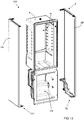
- Figures 1 and 2 show a refrigeration appliance 1, or refrigerator 1, according to a preferred embodiment of the invention.
- the refrigerator 1 shown in the figures is a refrigerator 1 in the form of a domestic refrigerator, also known as compact refrigerator.
- the refrigerator 1 also preferably refers to a built-in solution.
- this first preferred embodiment described in detail below refers to a single door refrigerator with a fresh food compartment.
- the refrigerator according to the invention can have any desired configuration, for example a top mount or a bottom mount refrigerator wherein a freezer compartment and a fresh food compartment are disposed vertically one the other, preferably closed with two respective doors.
- the refrigerator 1 preferably comprises an outer cabinet 2 and an inner liner 6, internally received in the outer cabinet 2.
- the outer cabinet 2 and the inner liner 6 are preferably separated by a spacing filled with thermal insulation material, preferably a foam insulation material.
- the outer cabinet 2 is preferably parallelepiped-shaped and preferably comprises side walls 2A, 2B, 2C, 2D, preferably two lateral side walls 2A, 2B, a rear side wall 2C and a top side wall 2D.
- lateral side walls 2A, 2B and the rear side wall 2C are preferably aligned to a vertical direction.
- the lateral side walls 2A, 2B (left side wall 2A and right side wall 2B) preferably extend from the front side to the rear side of the refrigerator 1.
- the inner liner 6 preferably defines a space that is used as a fresh food compartment 10 ( Figure 4 ).
- a door 15 is preferably pivotally mounted to the outer cabinet 2 and is movable between an open position and a closed position to cover the fresh food compartment 10.
- a refrigeration system (not shown) is preferably provided to cool the compartment 10, more preferably the refrigeration system is apt to cool down air which is circulated inside the compartment 10.
- the refrigeration system preferably comprises components configured to generate said cooling air flow.
- the refrigeration system preferably comprises a closed recirculating system filled with a suitable refrigerant, for example R12 or R134a.
- the refrigeration system preferably comprises an electric motor-driven compressor, a condenser heat exchanger, a pressure device such as a capillary tube or a thermostatic valve and an evaporator, which eventually define said components (not shown).
- a fan is also preferably used to circulate the cooled air inside the compartment 10.
- Some of said components for example the compressor and the capillary tube, are preferably arranged in a chamber 20 of the refrigerator 1, or working chamber 20.
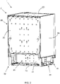
- the working chamber 20 is preferably arranged at the back side of the refrigerator 1 and preferably at a bottom part of the rear side wall 2C.
- the working chamber 20 is preferably thermally-insulated and/or sound-insulated, in particular thermally-insulated with respect to the compartment 10.
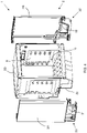
- a shaped insulating panel 22 is thus preferably interposed between the working chamber 20 and the compartment 10, as depicted in Figures 2 and 4 .
- the refrigerator 1 comprises at least one base support 30, 32 arranged at its lower side.
- a first base support 30, or left support 30, is aligned to, and substantially arranged below, the left side wall 2A and a second base support 32, or right support 32, is aligned to, and substantially arranged below, the right side wall 2B.
- the base supports 30, 32 advantageously support the refrigerator 1 when the latest is positioned in its standing working position.
- the at least one base support 30, 32 at least partially delimits the working chamber 20; more preferably the two base supports 30, 32 at least partially laterally delimit the working chamber 20.
- the working chamber 20 is then preferably delimited by the insulating panel 22 in the back-to-front direction while the working chamber 20 is preferably open towards the outside so that it can be conveniently accessible in case of maintenance. Furthermore, dissipation of heat produced by components inside the working chamber 20 is enhanced, in particular heat produced by the compressor.
- the base support 30, 32 comprises a single body extending from the front side to the rear side of the refrigerator 1.
- the base support 30, 32 is constituted of a plastic single body, more preferably is moulded via an injection moulding process.
- reduction of weight is reached.
- the base support 30, 32 comprises an insert element 31, 33 fixedly connected to the base support 30, 32.
- the insert element 31, 33 may be preferably realized with a self-extinguishing material.
- the first/left base support 30 extends, together with the first/left side wall 2A, from the front side to the rear side of the refrigerator 1 and, analogously, the second/right base support 32 extends, together with the second/right side wall 2B, from the front side to the rear side of the refrigerator 1.
- the base support 30, 32 preferably comprises a first recess 34 apt to receive a first lower edge 22A of the lateral side wall 2A, 2B and a second recess 38 apt to receive a second edge 24A of the lateral side wall 2A, 2B.
- first base support 30 and the first side wall 2A may be easily extended to the second base support 32 and the second side wall 2B.
- the first base support 30 comprises a first recess 34 apt to receive a first lower edge 22A of the first side wall 2A and a second recess 38 apt to receive a second edge 24A of the first side wall 2A for the connection of the first base support 30 to the first side wall 2A.
- the second base support 32 comprises a first recess apt to receive a first lower edge of the second side wall 2B and a second recess apt to receive a second edge of the second side wall 2B for the connection of the second base support 30 to the second side wall 2B.
- the first recess 34 and the first lower edge 22A preferably extend horizontally when the refrigerator 1 is placed in its standing working position.
- the second recess 38 and the second edge 24A preferably extend vertically when the refrigerator 1 is placed in its standing working position.
- the first recess 34 and the second recess 38 are therefore preferably perpendicular one to the other.
- the first lower edge 22A and the second edge 24A are therefore preferably perpendicular one to the other.
- the first lower edge 22A and the second edge 24A represent two edges of the panel that constitutes the respective rectangular side wall 2A, 2B.
- the panel is typically embodied as a metallic panel, wherein the first lower edge 22A and the second edge 24A are edges obtained by perimetrically folding the metallic panel.
- first recess and the first lower edge preferably extend along a first preferred direction and the second recess and the second edge preferably extend along a second preferred direction when the refrigerator is placed in its standing working position.
- the first direction and the second direction are preferably inclined one to the other, more preferably perpendicular one to the other as described above for the first preferred embodiment illustrated in the figures.
- connection of the first base support 30 to the first side wall 2A and/or the connection of the second base support 30 to the second side wall 2B is preferably a snap connection. Therefore, preferably, the first recess 34 and the first lower edge 22A are provided with a snap connection device. Also, preferably, the second recess 38 and the second edge 24A are provided with a snap connection device.
- Snap connection devices make the connection of the lateral side walls 2A, 2B to the base supports 30, 32 easy and optimize assembling operations of the refrigerator 1.
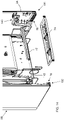
- the first recess 34 preferably comprises at least a retaining tooth 54A and the first lower edge 22A comprises at least a respective receiving hole 56A (shown in Figure 7A ) for the insertion of the retaining tooth 54A to obtain said snap connection.
- the first recess 34 further comprises at least a rib 58A apt to abut against the first lower edge 22A when the first lower edge 22A is inserted into the first recess 34.
- the ribs 58A preferably have a guide function during insertion of the first lower edge 22A into the first recess 34 and, once inserted, keep the first lower edge 22A firmly in position into the first recess 34.
- the second recess 38 comprises at least a retaining tooth 60A and the second edge 24A comprises at least a respective receiving hole 62A (shown in Figure 7A ) for the insertion of the retaining tooth 60A to obtain said snap connection.
- the second recess 38 further comprises at least a rib 64A apt to abut against the second edge 24A when the second edge 24A is inserted into the second recess 38.
- the ribs 64A preferably have a guide function during insertion of the second edge 24A into the second recess 38 and, once inserted, keep the second edge 24A firmly in position into the second recess 38.
- a further fixation device (not shown) can be provided, for example a screw fixation, between the base support and the first/second lower edge, to finally fixing these components therebetween.
- the base supports 30, 32 in a single body that extends from the front side to the rear side of the refrigerator 1 and by providing the connection of the base support 30, 32 with two different edges 22A, 24A of the lateral side wall 2A, 2B it is possible to improve the structural strength of the refrigerator 1 compared to known refrigerators.
- the base supports 30, 32 in a single body that extends from the front side to the rear side of the refrigerator 1 and by providing the connection of the base support 30, 32 with two different edges 22A, 24A of the lateral side wall 2A, 2B it is possible to decrease the needed components for manufacturing the appliance and/or to handling a lower number of components and hence simplifying manufacturing process.
- the base supports 30, 32 in a single body that extends from the front side to the rear side of the refrigerator 1 and by providing the connection of the base support 30, 32 with two different edges 22A, 24A of the lateral side wall 2A, 2B it is possible to provide a common subassembly that can be used for the realization of several refrigerator models.
- the subassembly preferably comprises the base support 30, 32 and the respective lateral side wall 2A, 2B which are connected therebetween.
- the first recess 34 is preferably arranged in an intermediate part of the base support 30, 32 so that the side wall 2A, 2B laterally partially covers the base support 30, 32 or, in other words, a lower part of the base support 30, 32 is not covered by the side wall 2A, 2B and is exposed directly to the outside.
- the lower part of the base support 30, 32 exposed directly to the outside involves majority of the base support 30, 32.
- the base supports 30, 32 eventually support the refrigerator 1 when the latest is positioned in its standing working position.
- the base supports 30, 32 preferably comprises one or more supporting legs 70 extending downwardly for placement of the refrigerator 1 on the floor.
- two front supporting legs 70 are shown.
- two supporting legs are arranged at the back of the base supports 30, 32.
- the supporting legs are embodied as adjustable levelling supporting legs so that their lengths can be opportunely adjusted when the refrigerator 1 is placed in its standing working position.
- a cross bar 72 then, preferably connects the two base supports 30, 32 ( Figures 3 and 5 ).
- the cross bar 72 is preferably arranged at the rear side of the base supports 30, 32, above the working chamber 20, and transversally connects the same.
- the cross bar 72 is preferably connected with screws to the base supports 30, 32.
- the cross bar 72 is preferably connected to the base supports 30, 32 at respective protrusions 40, 42 inwardly extending from the base supports 30, 32, as shown in Figure 5 .
- the cross bar 72 advantageously improves stability and stiffness of base supports 30, 32.
- the base supports 30, 32 are opportunely configured to receive a supporting element 74 which is preferably arranged in the lower part of the working chamber 20, preferably to support components inside the working chamber 20 more preferably to support the compressor.
- the supporting element 74 is preferably removably associated to the base supports 30, 32.
- slits 76, 78 are realized at the base supports 30, 32 to slidingly receive lateral sides of the supporting element 74.
- the refrigerator 101 shown in the figures is a stand-alone bottom mount refrigerator 101, i.e. of the type including a freezer compartment 110 disposed vertically below a fresh food compartment 10.
- the refrigerator 101 preferably comprises an outer cabinet 2 and an inner liner 6, internally received in the outer cabinet 2.
- the outer cabinet 2 and the inner liner 6 are preferably separated by a spacing filled with thermal insulation material, preferably a foam insulation material.
- the outer cabinet 2 is preferably parallelepiped-shaped and preferably comprises side walls 2A, 2B, 2C, 2D, preferably two lateral side walls 2A, 2B, a rear side wall 2C and a top side wall 2D.
- lateral side walls 2A, 2B and the rear side wall 2C are preferably aligned to a vertical direction.
- the lateral side walls 2A, 2B (left side wall 2A and right side wall 2B) preferably extend from the front side to the rear side of the refrigerator 101.
- the inner liner 6 preferably defines a lower space that is used as a freezer compartment 110 and an upper space that is used as a fresh food compartment 10.
- a first door 15 is preferably pivotally mounted to the outer cabinet 2 and is movable between an open position and a closed position to cover the fresh food compartment 10 and a second door 115 is preferably pivotally mounted to the outer cabinet 2 and is movable between an open position and a closed position to cover the freezer compartment 110.
- the doors 15, 115 are mounted in the right-swing configuration and hence they can rotate around respective hinge points 15a, 15b, 115a, 115b.
- a refrigeration system (not shown) is preferably provided to cool the compartments 10, 110, more preferably the refrigeration system is apt to cool down air which is circulated inside the compartments 10, 110.
- the refrigeration system preferably comprises components configured to generate said cooling air flows, as described above.
- Some of said components are preferably arranged in a working chamber 20 of the refrigerator 101.
- the working chamber 20 is preferably arranged at the back side of the refrigerator 101 and preferably at a bottom part of the rear side wall 2C.
- the working chamber 20 is preferably thermally-insulated and/or sound-insulated, in particular thermally-insulated with respect to the freezer compartment 110.
- a shaped insulating panel 22 is thus preferably interposed between the working chamber 20 and the freezer compartment 110, as depicted in Figure 11 .
- the refrigerator 101 comprises at least one base support 130, 132 arranged at its lower side.
- a first base support 130, or left support 130 is aligned to, and substantially arranged below, the left side wall 2A and a second base support 132, or right support 132, is aligned to, and substantially arranged below, the right side wall 2B.
- the base supports 130, 132 advantageously support the refrigerator 101 when the latest is positioned in its standing working position.
- the at least one base support 130, 132 at least partially delimits the working chamber 20; more preferably the two base supports 130, 132 at least partially laterally delimit the working chamber 20.
- the working chamber 20 is then preferably delimited by the insulating panel 22 in the back-to-front direction while the working chamber 20 is preferably open towards the outside.
- the base support 130, 132 comprises a single body extending from the front side to the rear side of the refrigerator 101.
- the base support 130, 132 is constituted of a plastic single body, more preferably is moulded via an injection moulding process.
- reduction of weight is reached.
- the first/left base support 130 extends, together with the first/left side wall 2A, from the front side to the rear side of the refrigerator 101 and, analogously, the second/right base support 132 extends, together with the second/right side wall 2B, from the front side to the rear side of the refrigerator 101.
- the base support 130, 132 preferably comprises a first recess 34 apt to receive a first lower edge 22A of the lateral side wall 2A, 2B and a second recess 38 apt to receive a second edge 24A of the lateral side wall 2A, 2B.
- first base support 130 and the first side wall 2A may be easily extended to the second base support 132 and the second side wall 2B.
- the first base support 130 comprises a first recess 34 apt to receive a first lower edge 22A of the first side wall 2A and a second recess 38 apt to receive a second edge 24A of the first side wall 2A for the connection of the first base support 130 to the first side wall 2A.
- the second base support 132 comprises a first recess apt to receive a first lower edge of the second side wall 2B and a second recess apt to receive a second edge of the second side wall 2B for the connection of the second base support 130 to the second side wall 2B.
- the first recess 34 and the first lower edge 22A preferably extend horizontally when the refrigerator 101 is placed in its standing working position.
- the second recess 38 and the second edge 24A preferably extend vertically when the refrigerator 101 is placed in its standing working position.
- the first recess 34 and the second recess 38 are therefore preferably perpendicular one to the other.
- the first lower edge 22A and the second edge 24A are therefore preferably perpendicular one to the other.
- the first lower edge 22A and the second edge 24A represent two edges of the panel that constitutes the respective rectangular side wall 2A, 2B.
- the panel is typically embodied as a metallic panel, wherein the first lower edge 22A and the second edge 24A are edges obtained by perimetrically folding the metallic panel.
- first recess and the first lower edge preferably extend along a first preferred direction and the second recess and the second edge preferably extend along a second preferred direction when the refrigerator is placed in its standing working position.
- the first direction and the second direction are preferably inclined one to the other, more preferably perpendicular one to the other as described above for the second preferred embodiment illustrated in the figures.
- connection of the first base support 130 to the first side wall 2A and/or the connection of the second base support 132 to the second side wall 2B is preferably a snap connection. Therefore, preferably, the first recess 34 and the first lower edge 22A are provided with a snap connection device. Also, preferably, the second recess 38 and the second edge 24A are provided with a snap connection device.
- Snap connection devices make the connection of the lateral side walls 2A, 2B to the base supports 130, 132 easy and optimize assembling operations of the refrigerator 101.
- the first recess 34 preferably comprises at least a retaining tooth 54A and the first lower edge 22A comprises at least a respective receiving hole 56A (shown in Figure 15 ) for the insertion of the retaining tooth 54A to obtain said snap connection.
- the first recess 34 further comprises at least a rib 58A apt to abut against the first lower edge 22A when the first lower edge 22A is inserted into the first recess 34.
- the ribs 58A preferably have a guide function during insertion of the first lower edge 22A into the first recess 34 and, once inserted, keep the first lower edge 22A firmly in position into the first recess 34.
- the second recess 38 comprises at least a retaining tooth 60A and the second edge 24A comprises at least a respective receiving hole 62A (shown in Figure 15 ) for the insertion of the retaining tooth 60A to obtain said snap connection.
- the second recess 38 further comprises at least a rib 64A apt to abut against the second edge 24A when the second edge 24A is inserted into the second recess 38.
- the ribs 64A preferably have a guide function during insertion of the second edge 24A into the second recess 38 and, once inserted, keep the second edge 24A firmly in position into the second recess 38.
- a further fixation device (not shown) can be provided, for example a screw fixation, between the base support and the first/second lower edge, to finally fixing these components therebetween.
- the base supports 130, 132 in a single body that extends from the front side to the rear side of the refrigerator 101 and by providing the connection of the base support 130, 132 with two different edges 22A, 24A of the lateral side wall 2A, 2B it is possible to improve the structural strength of the refrigerator 101 compared to known refrigerators.
- the base supports 130, 132 in a single body that extends from the front side to the rear side of the refrigerator 101 and by providing the connection of the base support 130, 132 with two different edges 22A, 24A of the lateral side wall 2A, 2B it is possible to decrease the needed components for manufacturing the appliance and/or to handling a lower number of components and hence simplifying manufacturing process.
- the base supports 130, 132 in a single body that extends from the front side to the rear side of the refrigerator 1 and by providing the connection of the base support 130, 132 with two different edges 22A, 24A of the lateral side wall 2A, 2B it is possible to provide a common subassembly that can be used for the realization of several refrigerator models.
- the subassembly preferably comprises the base support 130, 132 and the respective lateral side wall 2A, 2B which are connected therebetween.
- the first recess 34 is preferably arranged in a lower part of the base support 130, 132 so that the side wall 2A, 2B laterally entirely covers the base support 130, 132 or, in other words, no one surface of the base support 130, 132 is exposed directly to the outside.
- the base supports 130, 132 eventually support the refrigerator 101 when the latest is positioned in its standing working position.
- the base supports 130, 132 preferably comprises one or more supporting legs 170a, 170b extending downwardly for placement of the refrigerator 101 on the floor, more preferably a right front leg 170a, a left front leg 171a, a rear right leg 170b and a left rear leg 171b.
- the right front leg 170a is preferably fixable to the second base support 132 through one or more screws (not shown).
- the right front leg 170a is preferably embodied as a shaped plate and further preferably comprises two seats 176a, 178a, one of these seats being apt to receive a hinge pin 174a for the second door 115.
- the hinge pin 174a is received in the first seat 176a of the right front leg 170a to allow rotation of the second door 115 in the chosen right-swing configuration.
- the same right front leg 170a may be used to form the left front leg 171b wherein, in this case, the hinge pin 174a is preferably associated to the second seat 178a.
- the right rear leg 170b is preferably fixable to the second base support 132 through mechanical interference.
- the right rear leg 170b preferably comprises two protruding tabs 174b apt to be received in respective seats (not sown) of the second base support 132.
- the left rear leg 171b is substantially identical to the right rear leg 170b.
- a cross bar 72 then, preferably connects the two base supports 130, 132 ( Figure 14 ).
- the cross bar 72 is preferably arranged at the rear side of the base supports 130, 132, above the working chamber 20, and transversally connects the same.
- the cross bar 72 is preferably connected with screws to the base supports 130, 132.
- the cross bar 72 is preferably connected to the base supports 130, 132 at respective protrusions 140, 142 inwardly extending from the base supports 130, 132, as shown in Figure 14 .
- the cross bar 72 advantageously improves stability and stiffness of base supports 130, 132.
- the base supports 130, 132 are opportunely configured to receive a supporting element 74 which is preferably arranged in the lower part of the working chamber 20, preferably to support components inside the working chamber 20 more preferably to support the compressor.
- the supporting element 74 is preferably removably associated to the base supports 130, 132.
- slits 76, 78 are realized at the base supports 130, 132 to slidingly receive lateral sides of the supporting element 74.
- the present invention allows all the set objects to be achieved.
- the refrigeration appliance of the invention makes it possible to improve the structural strength of the appliance compared to known refrigeration appliances.
Landscapes
- Engineering & Computer Science (AREA)
- Chemical & Material Sciences (AREA)
- Combustion & Propulsion (AREA)
- Physics & Mathematics (AREA)
- Mechanical Engineering (AREA)
- Thermal Sciences (AREA)
- General Engineering & Computer Science (AREA)
- Refrigerator Housings (AREA)
Abstract
Description
- The present invention relates to a refrigeration appliance, in particular to a refrigeration appliance provided with a working chamber receiving components for the functioning of the appliance.
- Nowadays refrigeration appliances are extensively used, in particular refrigeration appliances for domestic use. We will refer, in particular, to refrigeration appliances comprising one or more compartments, for example fresh food compartments and/or freezer compartments, for the storage of food and/or beverages.
- A refrigeration appliance, hereinafter indicated simply with the term refrigerator, typically comprises a parallelepiped-shaped outer cabinet apt to place the refrigerator in a standing working position, typically placed on a horizontal floor.
- The refrigerator is then opportunely equipped with components allowing functioning of the same. For example, the refrigeration is equipped with a refrigeration system apt to cool the compartments and comprising an electric motor-driven compressor, a condenser heat exchanger, a capillary tube and an evaporator.
- Part of the components are preferably arranged in a proper chamber of the refrigerator, or working chamber, which can be conveniently accessible in case of maintenance and also preferably isolated from the rest of the refrigerator.
- Refrigerators of known type are thus preferably provided with an isolated working chamber receiving one or more of said components (compressor, capillary tube, etc.) and preferably arranged on the bottom of the cabinet at its back side.
- The realization of the working chamber has a relevant impact on the structural strength of the cabinet and hence on the structural strength of the refrigerator as a whole.
- A particular focus in manufacturing of refrigerators, therefore, is the most efficiency design of the working chamber both in terms of impact of the working chamber on the structural strength of the cabinet and in terms of assembling time and costs of the refrigerator.
- The realization of the working chamber requires several components, such as pleated sheet metals, brackets, insulating materials, that firstly implies several manufacturing steps for assembling the components in the correct reciprocal position.
- At the same time, high number of components determines a complicated way to provide a reliable insulation of the working chamber.
- Furthermore, the realization of different refrigerator models requires a huge amount of different components. Therefore, manufactures have to face with complicated components management and handling of the same components during manufacturing may also be difficult.
- One object of the present invention is therefore to overcome the limits posed by the known techniques.
- It is an object of the invention to provide a refrigeration appliance that improves the structural strength of the appliance compared to known refrigeration appliances.
- It is another object of the invention to provide a refrigeration appliance that optimizes assembling operations compared to known techniques.
- It is a further object of the invention to achieve an easier manufacturing and components management for manufactures compares to known system.
- The applicant has found that by providing a refrigeration appliance having an outer cabinet comprising at least one lateral side wall that extends from a front side to a rear side of the appliance, a working chamber apt to receive at least one component for the functioning of the appliance, at least one base support at least partially delimiting said working chamber, wherein the base support comprises a single body extending from the front side to the rear side of the appliance and by providing the base support with recesses apt to receive respective edges of the lateral side wall, it is possible to improve the structural strength of the appliance and/or to decrease the needed components and/or to provide a common subassembly that can be used for several refrigerator models and/or to simplify the manufacturing process.
- According to one aspect of the present disclosure there is provided a refrigeration appliance apt to be positioned in a standing working position and having a front side and a rear side, said appliance comprising:
- an outer cabinet comprising at least one lateral side wall that extends from said front side to said rear side;
- a working chamber apt to receive at least one component for the functioning of said appliance, said working chamber being arranged at a bottom part of said appliance;
- at least one base support for said appliance, said base support at least partially delimiting said working chamber;
- Advantageously, by providing the base supports in a single body that extends from the front side to the rear side of the appliance and by providing the connection of the base support with two different edges of the lateral side wall it is possible to improve the structural strength of the appliance compared to known refrigeration appliances.
- Moreover, by providing the base supports in a single body it is possible to decrease the needed components for manufacturing the appliance and/or to handling a lower number of components and hence simplifying manufacturing process.
- Still advantageously, by providing the base supports in a single body that extends from the front side to the rear side of the appliance and by providing the connection of the base support with two different edges of the lateral side wall it is possible to provide a common subassembly that can be used for several refrigeration appliance models. The subassembly preferably comprises the base support and the respective lateral side wall which are connected therebetween.
- Preferably, said first lower edge and/or said second edge is a folded edge of the lateral side wall, more preferably a folded edge of the lateral side wall when made of metal.
- Therefore, the lateral side wall is preferably embodied as a metallic panel, wherein the first lower edge and the second edge are edges obtained by perimetrically folding the metallic panel.
- In a preferred embodiment, the first recess is arranged in a lower part of the base support so that the lateral side wall laterally entirely covers the base support.
- Advantageously, aesthetic appearance of the appliance is improved.
- According to a further preferred embodiment of the invention, the first recess is arranged in an intermediate part of the base support so that the lateral side wall laterally partially covers the base support.
- Preferably, the first recess and the first lower edge extend along a first preferred direction and the second recess and the second edge extend along a second preferred direction when the appliance is placed in its standing working position, wherein the first direction and the second direction are preferably inclined one to the other, more preferably are perpendicular one to the other.
- Preferably, the first recess and the first lower edge extend horizontally when the appliance is placed in its standing working position.
- In a preferred embodiment, the second recess and the second edge extend vertically when the appliance is placed in its standing working position.
- The first lower edge and the second edge are preferably perpendicular one to the other and/or the first recess and the second recess are preferably perpendicular one to the other.
- Advantageously, the structural strength of the appliance if further improved compared to known appliances.
- According to a preferred embodiment of the invention, the first recess and the first lower edge are further provided with a snap connection device and/or the second recess and the second edge are further provided with a snap connection device.
- Advantageously, the snap connection devices make the connection of the lateral side wall to the base support easy and optimize assembling operations of the appliance.
- Preferably, a further fixation device can be provided, for example a screw fixation, between the base support and the first/second lower edge, to finally fixing these components therebetween.
- Preferably, the first recess comprises a retaining tooth and the first lower edge comprises a receiving hole for the insertion of the retaining tooth or the first lower edge comprises a retaining tooth and the first recess comprises a receiving hole for the insertion of the retaining tooth.
- Preferably, the second recess comprises a retaining tooth and the second edge comprises a receiving hole for the insertion of the retaining tooth or the second edge comprises a retaining tooth and the second recess comprises a receiving hole for the insertion of the retaining tooth.
- In a preferred embodiment, the base support is constituted of a plastic single body. Preferably, the base support is moulded via an injection moulding process.
- Advantageously, reduction of weight is reached.
- Furthermore, advantageously, the common subassembly constituted of the base support and the respective lateral side wall can be used for several refrigeration appliance models.
- According to a preferred embodiment of the invention, the base support further comprises one or more supporting legs extending downwardly for placement of the appliance on the floor.
- Preferably, the legs are constituted of supporting adjustable levelling supporting legs.
- The legs are preferably fixable to the base support by means of screws and/or by mechanical interference.
- In a preferred embodiment of the invention, the leg further comprises at least one seat apt to receive a hinge pin for a door of the refrigeration appliance.
- Preferably, the working chamber is arranged on the back side of the appliance.
- In a preferred embodiment, said at least one lateral side wall comprises two lateral side walls facing each other and said at least one base support comprises two base supports facing each other and associated to a respective lateral side, said two base supports at least partially laterally delimiting said working chamber.
- According to a preferred embodiment of the invention, there is provided a cross bar connecting the two base supports.
- Preferably, each of said two base supports comprises means for the connection to said cross bar, wherein said means preferably comprise a protrusion extending from the base support apt to be connected to an extremity of the cross bar.
- Advantageously, stability and stiffness of the base supports are improved.
- Preferably, there is provided a supporting element arranged in the lower part of the working chamber.
- In a preferred embodiment, said at least one base support comprises at least one slit apt to slidingly receive the supporting element.
- Further characteristics and advantages of the present invention will be highlighted in greater detail in the following detailed description of preferred embodiments of the invention, provided with reference to the enclosed drawings. In such drawings:
-
Figure 1 shows a front perspective view of a refrigeration appliance according to a preferred embodiment of the invention; -
Figure 2 shows a rear perspective view of the appliance ofFigure 1 ; -
Figure 3 shows the appliance ofFigure 2 with some elements removed therefrom; -
Figure 4 shows an exploded view ofFigure 1 ; -
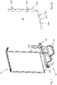
Figure 5 shows an exploded view of a detail ofFigure 3 ; -
Figure 6 shows an exploded view of elements ofFigure 4 isolated from the rest; -
Figure 7 shows the elements ofFigure 6 from another point of view; -
Figure 7A shows an enlarged view of a detail ofFigure 7 ; -
Figure 8 shows an enlarged view of a detail ofFigure 6 ; -
Figure 9A shows an enlarged view of a detail ofFigure 8 ; -
Figure 9B shows an enlarged view of another detail ofFigure 8 ; -
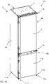
Figure 10 shows a front perspective view of a refrigeration appliance according to a further preferred embodiment of the invention; -
Figure 11 shows a rear perspective view of the appliance ofFigure 10 ; -
Figure 12 shows the appliance ofFigure 11 with some elements removed therefrom; -
Figure 13 shows an exploded view ofFigure 10 ; -
Figure 14 shows an exploded view of a detail ofFigure 12 ; -
Figure 15 shows an enlarged detail ofFigure 14 ; -
Figure 16 shows an element ofFigure 15 from another point of view; -
Figure 17A shows an enlarged view of a detail ofFigure 16 ; -
Figure 17B shows an enlarged view of another detail ofFigure 16 ; -
Figure 18 shows a partially exploded view of a detail ofFigure 12 ; -
Figure 18A shows an enlarged view of a detail ofFigure 18 ; -
Figure 19 shows another partially exploded view of a detail ofFigure 12 . - The refrigeration appliance according to the present invention has proved to be particularly advantageous when refers to a refrigeration appliance for domestic use. It should in any case be underlined that the present invention is not limited to this particular embodiment. On the contrary, the present invention conveniently refers to any refrigeration appliance being provided with a working chamber wherein components for the functioning of the refrigeration appliance are arranged.
-
Figures 1 and2 show arefrigeration appliance 1, orrefrigerator 1, according to a preferred embodiment of the invention. - The
refrigerator 1 shown in the figures is arefrigerator 1 in the form of a domestic refrigerator, also known as compact refrigerator. Therefrigerator 1 also preferably refers to a built-in solution. - Furthermore, this first preferred embodiment described in detail below refers to a single door refrigerator with a fresh food compartment.
- However, the refrigerator according to the invention can have any desired configuration, for example a top mount or a bottom mount refrigerator wherein a freezer compartment and a fresh food compartment are disposed vertically one the other, preferably closed with two respective doors.
- Furthermore, while the first preferred embodiment is described with reference to a built-in refrigerator it has to be noted that also a stand-alone solution may be contemplated.
- The
refrigerator 1 preferably comprises anouter cabinet 2 and aninner liner 6, internally received in theouter cabinet 2. Theouter cabinet 2 and theinner liner 6 are preferably separated by a spacing filled with thermal insulation material, preferably a foam insulation material. - The
outer cabinet 2 is preferably parallelepiped-shaped and preferably comprisesside walls lateral side walls rear side wall 2C and atop side wall 2D. - In its standing working position,
lateral side walls rear side wall 2C are preferably aligned to a vertical direction. - The
lateral side walls left side wall 2A andright side wall 2B) preferably extend from the front side to the rear side of therefrigerator 1. - The
inner liner 6 preferably defines a space that is used as a fresh food compartment 10 (Figure 4 ). - A
door 15 is preferably pivotally mounted to theouter cabinet 2 and is movable between an open position and a closed position to cover thefresh food compartment 10. - A refrigeration system (not shown) is preferably provided to cool the
compartment 10, more preferably the refrigeration system is apt to cool down air which is circulated inside thecompartment 10. - The refrigeration system preferably comprises components configured to generate said cooling air flow. The refrigeration system preferably comprises a closed recirculating system filled with a suitable refrigerant, for example R12 or R134a. The refrigeration system preferably comprises an electric motor-driven compressor, a condenser heat exchanger, a pressure device such as a capillary tube or a thermostatic valve and an evaporator, which eventually define said components (not shown). A fan is also preferably used to circulate the cooled air inside the
compartment 10. - Some of said components, for example the compressor and the capillary tube, are preferably arranged in a
chamber 20 of therefrigerator 1, or workingchamber 20. - The working
chamber 20 is preferably arranged at the back side of therefrigerator 1 and preferably at a bottom part of therear side wall 2C. - The working
chamber 20 is preferably thermally-insulated and/or sound-insulated, in particular thermally-insulated with respect to thecompartment 10. A shaped insulatingpanel 22 is thus preferably interposed between the workingchamber 20 and thecompartment 10, as depicted inFigures 2 and4 . - According to an aspect of the invention, the
refrigerator 1 comprises at least onebase support - In the preferred embodiment illustrated herein, there are provided two base supports 30, 32 facing each other and preferably aligned with respective
lateral side walls first base support 30, or leftsupport 30, is aligned to, and substantially arranged below, theleft side wall 2A and asecond base support 32, orright support 32, is aligned to, and substantially arranged below, theright side wall 2B. - The base supports 30, 32 advantageously support the
refrigerator 1 when the latest is positioned in its standing working position. - Preferably, the at least one
base support chamber 20; more preferably the two base supports 30, 32 at least partially laterally delimit the workingchamber 20. - The working
chamber 20 is then preferably delimited by the insulatingpanel 22 in the back-to-front direction while the workingchamber 20 is preferably open towards the outside so that it can be conveniently accessible in case of maintenance. Furthermore, dissipation of heat produced by components inside the workingchamber 20 is enhanced, in particular heat produced by the compressor. - According to an aspect of the invention, the
base support refrigerator 1. Preferably, thebase support - Preferably, the
base support insert element base support insert element - Preferably, the first/left
base support 30 extends, together with the first/left side wall 2A, from the front side to the rear side of therefrigerator 1 and, analogously, the second/right base support 32 extends, together with the second/right side wall 2B, from the front side to the rear side of therefrigerator 1. According to another aspect of the invention, thebase support first recess 34 apt to receive a firstlower edge 22A of thelateral side wall second recess 38 apt to receive asecond edge 24A of thelateral side wall - Hereinafter, the detailed description will preferably refer to drawing relating
recesses edges first base support 30 and of thefirst side wall 2A. It is clear that what described for thefirst base support 30 and thefirst side wall 2A may be easily extended to thesecond base support 32 and thesecond side wall 2B. - Preferably, the
first base support 30 comprises afirst recess 34 apt to receive a firstlower edge 22A of thefirst side wall 2A and asecond recess 38 apt to receive asecond edge 24A of thefirst side wall 2A for the connection of thefirst base support 30 to thefirst side wall 2A. - Analogously, the
second base support 32 comprises a first recess apt to receive a first lower edge of thesecond side wall 2B and a second recess apt to receive a second edge of thesecond side wall 2B for the connection of thesecond base support 30 to thesecond side wall 2B. - The
first recess 34 and the firstlower edge 22A preferably extend horizontally when therefrigerator 1 is placed in its standing working position. - The
second recess 38 and thesecond edge 24A preferably extend vertically when therefrigerator 1 is placed in its standing working position. - The
first recess 34 and thesecond recess 38 are therefore preferably perpendicular one to the other. The firstlower edge 22A and thesecond edge 24A are therefore preferably perpendicular one to the other. In fact, preferably, the firstlower edge 22A and thesecond edge 24A represent two edges of the panel that constitutes the respectiverectangular side wall - The panel is typically embodied as a metallic panel, wherein the first
lower edge 22A and thesecond edge 24A are edges obtained by perimetrically folding the metallic panel. - Generally, the first recess and the first lower edge preferably extend along a first preferred direction and the second recess and the second edge preferably extend along a second preferred direction when the refrigerator is placed in its standing working position. The first direction and the second direction are preferably inclined one to the other, more preferably perpendicular one to the other as described above for the first preferred embodiment illustrated in the figures.
- The connection of the
first base support 30 to thefirst side wall 2A and/or the connection of thesecond base support 30 to thesecond side wall 2B is preferably a snap connection. Therefore, preferably, thefirst recess 34 and the firstlower edge 22A are provided with a snap connection device. Also, preferably, thesecond recess 38 and thesecond edge 24A are provided with a snap connection device. - Snap connection devices make the connection of the
lateral side walls refrigerator 1. - As illustrated in
Figure 9A , thefirst recess 34 preferably comprises at least a retainingtooth 54A and the firstlower edge 22A comprises at least arespective receiving hole 56A (shown inFigure 7A ) for the insertion of the retainingtooth 54A to obtain said snap connection. - Preferably, the
first recess 34 further comprises at least arib 58A apt to abut against the firstlower edge 22A when the firstlower edge 22A is inserted into thefirst recess 34. Theribs 58A preferably have a guide function during insertion of the firstlower edge 22A into thefirst recess 34 and, once inserted, keep the firstlower edge 22A firmly in position into thefirst recess 34. - Analogously, as illustrated in
Figure 9B , thesecond recess 38 comprises at least a retainingtooth 60A and thesecond edge 24A comprises at least arespective receiving hole 62A (shown inFigure 7A ) for the insertion of the retainingtooth 60A to obtain said snap connection. - Preferably, the
second recess 38 further comprises at least arib 64A apt to abut against thesecond edge 24A when thesecond edge 24A is inserted into thesecond recess 38. Theribs 64A preferably have a guide function during insertion of thesecond edge 24A into thesecond recess 38 and, once inserted, keep thesecond edge 24A firmly in position into thesecond recess 38. - Preferably, a further fixation device (not shown) can be provided, for example a screw fixation, between the base support and the first/second lower edge, to finally fixing these components therebetween.
- Advantageously, by providing the base supports 30, 32 in a single body that extends from the front side to the rear side of the
refrigerator 1 and by providing the connection of thebase support different edges lateral side wall refrigerator 1 compared to known refrigerators. - Moreover, advantageously, by providing the base supports 30, 32 in a single body that extends from the front side to the rear side of the
refrigerator 1 and by providing the connection of thebase support different edges lateral side wall - Still advantageously, by providing the base supports 30, 32 in a single body that extends from the front side to the rear side of the
refrigerator 1 and by providing the connection of thebase support different edges lateral side wall - The subassembly preferably comprises the
base support lateral side wall - The
first recess 34 is preferably arranged in an intermediate part of thebase support side wall base support base support side wall figures 1 to 9 , the lower part of thebase support base support - As explained, the base supports 30, 32 eventually support the
refrigerator 1 when the latest is positioned in its standing working position. - At this purpose, the base supports 30, 32 preferably comprises one or more supporting
legs 70 extending downwardly for placement of therefrigerator 1 on the floor. InFigure 1 , two front supportinglegs 70 are shown. Preferably, also two supporting legs (not shown) are arranged at the back of the base supports 30, 32. - In a preferred embodiment, the supporting legs are embodied as adjustable levelling supporting legs so that their lengths can be opportunely adjusted when the
refrigerator 1 is placed in its standing working position. - A
cross bar 72, then, preferably connects the two base supports 30, 32 (Figures 3 and5 ). In the preferred embodiment illustrated in the figures, thecross bar 72 is preferably arranged at the rear side of the base supports 30, 32, above the workingchamber 20, and transversally connects the same. Thecross bar 72 is preferably connected with screws to the base supports 30, 32. - More preferably, the
cross bar 72 is preferably connected to the base supports 30, 32 atrespective protrusions Figure 5 . - The
cross bar 72 advantageously improves stability and stiffness of base supports 30, 32. - Furthermore, the base supports 30, 32 are opportunely configured to receive a supporting
element 74 which is preferably arranged in the lower part of the workingchamber 20, preferably to support components inside the workingchamber 20 more preferably to support the compressor. - The supporting
element 74 is preferably removably associated to the base supports 30, 32. Preferably, slits 76, 78 are realized at the base supports 30, 32 to slidingly receive lateral sides of the supportingelement 74. - With reference to
Figures 10 to 17 arefrigerator 101 according to a further preferred embodiment of the invention is described. In the drawings, corresponding characteristics and/or components compared to previous preferred embodiment are identified by the same reference numbers. - The
refrigerator 101 shown in the figures is a stand-alonebottom mount refrigerator 101, i.e. of the type including afreezer compartment 110 disposed vertically below afresh food compartment 10. - The
refrigerator 101 preferably comprises anouter cabinet 2 and aninner liner 6, internally received in theouter cabinet 2. Theouter cabinet 2 and theinner liner 6 are preferably separated by a spacing filled with thermal insulation material, preferably a foam insulation material. - The
outer cabinet 2 is preferably parallelepiped-shaped and preferably comprisesside walls lateral side walls rear side wall 2C and atop side wall 2D. - In its standing working position,
lateral side walls rear side wall 2C are preferably aligned to a vertical direction. - The
lateral side walls left side wall 2A andright side wall 2B) preferably extend from the front side to the rear side of therefrigerator 101. - The
inner liner 6 preferably defines a lower space that is used as afreezer compartment 110 and an upper space that is used as afresh food compartment 10. - A
first door 15 is preferably pivotally mounted to theouter cabinet 2 and is movable between an open position and a closed position to cover thefresh food compartment 10 and asecond door 115 is preferably pivotally mounted to theouter cabinet 2 and is movable between an open position and a closed position to cover thefreezer compartment 110. - The
doors respective hinge points - A refrigeration system (not shown) is preferably provided to cool the
compartments compartments - The refrigeration system preferably comprises components configured to generate said cooling air flows, as described above.
- Some of said components are preferably arranged in a working
chamber 20 of therefrigerator 101. - The working
chamber 20 is preferably arranged at the back side of therefrigerator 101 and preferably at a bottom part of therear side wall 2C. - The working
chamber 20 is preferably thermally-insulated and/or sound-insulated, in particular thermally-insulated with respect to thefreezer compartment 110. A shaped insulatingpanel 22 is thus preferably interposed between the workingchamber 20 and thefreezer compartment 110, as depicted inFigure 11 . - According to an aspect of the invention, the
refrigerator 101 comprises at least onebase support - In the preferred embodiment illustrated herein, there are provided two base supports 130, 132 facing each other and preferably aligned with respective
lateral side walls first base support 130, or leftsupport 130, is aligned to, and substantially arranged below, theleft side wall 2A and asecond base support 132, orright support 132, is aligned to, and substantially arranged below, theright side wall 2B. - The base supports 130, 132 advantageously support the
refrigerator 101 when the latest is positioned in its standing working position. - Preferably, the at least one
base support chamber 20; more preferably the two base supports 130, 132 at least partially laterally delimit the workingchamber 20. - The working
chamber 20 is then preferably delimited by the insulatingpanel 22 in the back-to-front direction while the workingchamber 20 is preferably open towards the outside. - According to an aspect of the invention, the
base support refrigerator 101. Preferably, thebase support - Preferably, the first/left
base support 130 extends, together with the first/left side wall 2A, from the front side to the rear side of therefrigerator 101 and, analogously, the second/right base support 132 extends, together with the second/right side wall 2B, from the front side to the rear side of therefrigerator 101. - According to another aspect of the invention, the
base support first recess 34 apt to receive a firstlower edge 22A of thelateral side wall second recess 38 apt to receive asecond edge 24A of thelateral side wall - Hereinafter, the detailed description will preferably refer to drawing relating
recesses edges first base support 130 and of thefirst side wall 2A. It is clear that what described for thefirst base support 130 and thefirst side wall 2A may be easily extended to thesecond base support 132 and thesecond side wall 2B. - Preferably, the
first base support 130 comprises afirst recess 34 apt to receive a firstlower edge 22A of thefirst side wall 2A and asecond recess 38 apt to receive asecond edge 24A of thefirst side wall 2A for the connection of thefirst base support 130 to thefirst side wall 2A. - Analogously, the
second base support 132 comprises a first recess apt to receive a first lower edge of thesecond side wall 2B and a second recess apt to receive a second edge of thesecond side wall 2B for the connection of thesecond base support 130 to thesecond side wall 2B. - The
first recess 34 and the firstlower edge 22A preferably extend horizontally when therefrigerator 101 is placed in its standing working position. - The
second recess 38 and thesecond edge 24A preferably extend vertically when therefrigerator 101 is placed in its standing working position. - The
first recess 34 and thesecond recess 38 are therefore preferably perpendicular one to the other. The firstlower edge 22A and thesecond edge 24A are therefore preferably perpendicular one to the other. In fact, preferably, the firstlower edge 22A and thesecond edge 24A represent two edges of the panel that constitutes the respectiverectangular side wall - The panel is typically embodied as a metallic panel, wherein the first
lower edge 22A and thesecond edge 24A are edges obtained by perimetrically folding the metallic panel. - Generally, the first recess and the first lower edge preferably extend along a first preferred direction and the second recess and the second edge preferably extend along a second preferred direction when the refrigerator is placed in its standing working position. The first direction and the second direction are preferably inclined one to the other, more preferably perpendicular one to the other as described above for the second preferred embodiment illustrated in the figures.
- The connection of the
first base support 130 to thefirst side wall 2A and/or the connection of thesecond base support 132 to thesecond side wall 2B is preferably a snap connection. Therefore, preferably, thefirst recess 34 and the firstlower edge 22A are provided with a snap connection device. Also, preferably, thesecond recess 38 and thesecond edge 24A are provided with a snap connection device. - Snap connection devices make the connection of the
lateral side walls refrigerator 101. - As illustrated in
Figure 17A , thefirst recess 34 preferably comprises at least a retainingtooth 54A and the firstlower edge 22A comprises at least arespective receiving hole 56A (shown inFigure 15 ) for the insertion of the retainingtooth 54A to obtain said snap connection. - Preferably, the
first recess 34 further comprises at least arib 58A apt to abut against the firstlower edge 22A when the firstlower edge 22A is inserted into thefirst recess 34. Theribs 58A preferably have a guide function during insertion of the firstlower edge 22A into thefirst recess 34 and, once inserted, keep the firstlower edge 22A firmly in position into thefirst recess 34. - Analogously, as illustrated in
Figure 17B , thesecond recess 38 comprises at least a retainingtooth 60A and thesecond edge 24A comprises at least arespective receiving hole 62A (shown inFigure 15 ) for the insertion of the retainingtooth 60A to obtain said snap connection. - Preferably, the
second recess 38 further comprises at least arib 64A apt to abut against thesecond edge 24A when thesecond edge 24A is inserted into thesecond recess 38. Theribs 64A preferably have a guide function during insertion of thesecond edge 24A into thesecond recess 38 and, once inserted, keep thesecond edge 24A firmly in position into thesecond recess 38. - Preferably, a further fixation device (not shown) can be provided, for example a screw fixation, between the base support and the first/second lower edge, to finally fixing these components therebetween.
- Advantageously, by providing the base supports 130, 132 in a single body that extends from the front side to the rear side of the
refrigerator 101 and by providing the connection of thebase support different edges lateral side wall refrigerator 101 compared to known refrigerators. - Moreover, advantageously, by providing the base supports 130, 132 in a single body that extends from the front side to the rear side of the
refrigerator 101 and by providing the connection of thebase support different edges lateral side wall - Still advantageously, by providing the base supports 130, 132 in a single body that extends from the front side to the rear side of the
refrigerator 1 and by providing the connection of thebase support different edges lateral side wall - The subassembly preferably comprises the
base support lateral side wall - The
first recess 34 is preferably arranged in a lower part of thebase support side wall base support base support - Advantageously, such a solution allows to improve the aesthetic appearance of the
refrigerator 101. - As explained, the base supports 130, 132 eventually support the
refrigerator 101 when the latest is positioned in its standing working position. - At this purpose, the base supports 130, 132 preferably comprises one or more supporting
legs refrigerator 101 on the floor, more preferably a rightfront leg 170a, a leftfront leg 171a, a rearright leg 170b and a leftrear leg 171b. - The right
front leg 170a, as shown inFigures 18 and 18A , is preferably fixable to thesecond base support 132 through one or more screws (not shown). - The right
front leg 170a is preferably embodied as a shaped plate and further preferably comprises twoseats hinge pin 174a for thesecond door 115. - According to the preferred embodiment illustrated in the Figures, the
hinge pin 174a is received in thefirst seat 176a of the rightfront leg 170a to allow rotation of thesecond door 115 in the chosen right-swing configuration. - In a different preferred embodiment wherein the second door is mounted in left-swing configuration, the same right
front leg 170a may be used to form the leftfront leg 171b wherein, in this case, thehinge pin 174a is preferably associated to thesecond seat 178a. - The right
rear leg 170b, as shown inFigure 19 , is preferably fixable to thesecond base support 132 through mechanical interference. - The right
rear leg 170b preferably comprises two protrudingtabs 174b apt to be received in respective seats (not sown) of thesecond base support 132. - The left
rear leg 171b is substantially identical to the rightrear leg 170b. - A
cross bar 72, then, preferably connects the two base supports 130, 132 (Figure 14 ). In the preferred embodiment illustrated in the figures, thecross bar 72 is preferably arranged at the rear side of the base supports 130, 132, above the workingchamber 20, and transversally connects the same. Thecross bar 72 is preferably connected with screws to the base supports 130, 132. - More preferably, the
cross bar 72 is preferably connected to the base supports 130, 132 atrespective protrusions Figure 14 . - The
cross bar 72 advantageously improves stability and stiffness of base supports 130, 132. - Furthermore, the base supports 130, 132 are opportunely configured to receive a supporting
element 74 which is preferably arranged in the lower part of the workingchamber 20, preferably to support components inside the workingchamber 20 more preferably to support the compressor. - The supporting
element 74 is preferably removably associated to the base supports 130, 132. Preferably, slits 76, 78 are realized at the base supports 130, 132 to slidingly receive lateral sides of the supportingelement 74. - It has thus been shown that the present invention allows all the set objects to be achieved. In particular, the refrigeration appliance of the invention makes it possible to improve the structural strength of the appliance compared to known refrigeration appliances.
- While the present invention has been described with reference to the particular embodiments shown in the figures, it should be noted that the present invention is not limited to the specific embodiments illustrated and described herein; on the contrary, further variants of the embodiments described herein fall within the scope of the present invention, which is defined in the claims.
a first recess apt to receive a first lower edge of said lateral side wall and a second recess apt to receive a second edge of said lateral side wall for the connection of said base support to said lateral side wall.
Claims (16)
- A refrigeration appliance (1; 101) apt to be positioned in a standing working position and having a front side and a rear side, said appliance (1; 101) comprising:- an outer cabinet (2) comprising at least one lateral side wall (2A, 2B) that extends from said front side to said rear side;- a working chamber (20) apt to receive at least one component for the functioning of said appliance (1; 101), said working chamber (20) being arranged at a bottom part of said appliance (1; 101);- at least one base support (30, 32; 130, 132) for said appliance (1; 101), said base support (30, 32; 130, 132) at least partially delimiting said working chamber (20);wherein said base support (30, 32; 130, 132) comprises a single body extending from said front side to said rear side of said appliance (1; 101) and wherein said base support (30, 32; 130, 132) further comprises:
a first recess (34) apt to receive a first lower edge (22A) of said lateral side wall (2A, 2B) and a second recess (38) apt to receive a second edge (24A) of said lateral side wall (2A, 2B) for the connection of said base support (30, 32; 130, 132) to said lateral side wall (2A, 2B). - An appliance (101) according to claim 1, wherein said first recess (34) is arranged in a lower part of said base support (130, 132) so that said lateral side wall (2A, 2B) laterally entirely covers said base support (130, 132).
- An appliance (1) according to claim 1, wherein said first recess (34) is arranged in an intermediate part of said base support (30, 32) so that said lateral side wall (2A, 2B) laterally partially covers said base support (30, 32).
- An appliance (1; 101) according to any of the preceding claims, wherein said first recess (34) and said first lower edge (22A) extend along a first preferred direction and said second recess (38) and said second edge (24A) extend along a second preferred direction when said appliance (1; 101) is placed in its standing working position, wherein said first direction and said second direction are preferably inclined one to the other.
- An appliance (1; 101) according to any of the preceding claims, wherein said first recess (34) and said first lower edge (22A) extend horizontally when said appliance (1; 101) is placed in its standing working position.
- An appliance (1; 101) according to any of the preceding claims, wherein said second recess (38) and said second edge (24A) extend vertically when said appliance (1; 101) is placed in its standing working position.
- An appliance (1; 101) according to any of the preceding claims, wherein said first recess (34) and said first lower edge (22A) are further provided with a snap connection device and/or wherein said second recess (38) and said second edge (24A) are further provided with a snap connection device.
- An appliance (1; 101) according to claim 7, wherein:- said first recess (34) comprises a retaining tooth (54A) and said first lower edge (22A) comprises a receiving hole (56A) for the insertion of said retaining tooth (54A) or said first lower edge (22A) comprises a retaining tooth and said first recess (34) comprises a receiving hole for the insertion of said retaining tooth; and/or- said second recess (38) comprises a retaining tooth (60A) and said second edge (24A) comprises a receiving hole (62A) for the insertion of said retaining tooth (60A) or said second edge (24A) comprises a retaining tooth and said second recess (38) comprises a receiving hole for the insertion of said retaining tooth.
- An appliance (1; 101) according to any of the preceding claims, wherein said base support (30, 32; 130, 132) is constituted of a plastic single body.
- An appliance (1; 101) according to any of the preceding claims, wherein said base support (30, 32; 130, 132) further comprises one or more supporting legs (70; 170a, 171a, 170b, 171b) extending downwardly for placement of said appliance (1; 101) on a floor, preferably one or more supporting adjustable levelling supporting legs (70).
- An appliance (1; 101) according to any of the preceding claims, wherein said working chamber (20) is arranged on the back side of said appliance (1; 101).
- An appliance (1; 101) according to any of the preceding claims, wherein said at least one lateral side wall (2A, 2B) comprises two lateral side walls (2A, 2B) facing each other and said at least one base support (30, 32; 130, 132) comprises two base supports (30, 32; 130, 132) facing each other and associated to a respective lateral side, said two base supports (30, 32; 130, 132) at least partially laterally delimiting said working chamber (20).
- An appliance (1; 101) according to claim 12, wherein it comprises a cross bar (72) connecting said two base supports (30, 32; 130, 132).
- An appliance (1; 101) according to claim 13, wherein each of said two base supports (30, 32; 130, 132) comprises means for the connection to said cross bar, wherein said means preferably comprise a protrusion (40, 42; 140, 142) extending from said base support (30, 32; 130, 132) apt to be connected to an extremity of said cross bar (72).
- An appliance (1; 101) according to any of the preceding claims, wherein it comprises a supporting element (74) arranged in the lower part of said working chamber (20).
- An appliance (1; 101) according to claim 15, wherein said at least one base support (30, 32; 130, 132) comprises at least one slit (76, 78) apt to slidingly receive said supporting element (74).
Priority Applications (1)
| Application Number | Priority Date | Filing Date | Title |
|---|---|---|---|
| EP21184701.7A EP4116651A1 (en) | 2021-07-09 | 2021-07-09 | Refrigeration appliance |
Applications Claiming Priority (1)
| Application Number | Priority Date | Filing Date | Title |
|---|---|---|---|
| EP21184701.7A EP4116651A1 (en) | 2021-07-09 | 2021-07-09 | Refrigeration appliance |
Publications (1)
| Publication Number | Publication Date |
|---|---|
| EP4116651A1 true EP4116651A1 (en) | 2023-01-11 |
Family
ID=76859458
Family Applications (1)
| Application Number | Title | Priority Date | Filing Date |
|---|---|---|---|
| EP21184701.7A Pending EP4116651A1 (en) | 2021-07-09 | 2021-07-09 | Refrigeration appliance |
Country Status (1)
| Country | Link |
|---|---|
| EP (1) | EP4116651A1 (en) |
Citations (4)
| Publication number | Priority date | Publication date | Assignee | Title |
|---|---|---|---|---|
| EP2295902A1 (en) * | 2009-07-21 | 2011-03-16 | Electrolux Home Products Corporation N.V. | Appliance for the preservation of food and related manufacturing process |
| EP2674709B1 (en) * | 2012-06-11 | 2020-08-19 | BSH Hausgeräte GmbH | Refrigerator and method for its production |
| KR20200104728A (en) * | 2019-02-27 | 2020-09-04 | 엘지전자 주식회사 | A refrigerator having machine room |
| EP2678624B1 (en) * | 2011-02-23 | 2021-04-07 | BSH Hausgeräte GmbH | Electric domestic appliance |
-
2021
- 2021-07-09 EP EP21184701.7A patent/EP4116651A1/en active Pending
Patent Citations (4)
| Publication number | Priority date | Publication date | Assignee | Title |
|---|---|---|---|---|
| EP2295902A1 (en) * | 2009-07-21 | 2011-03-16 | Electrolux Home Products Corporation N.V. | Appliance for the preservation of food and related manufacturing process |
| EP2678624B1 (en) * | 2011-02-23 | 2021-04-07 | BSH Hausgeräte GmbH | Electric domestic appliance |
| EP2674709B1 (en) * | 2012-06-11 | 2020-08-19 | BSH Hausgeräte GmbH | Refrigerator and method for its production |
| KR20200104728A (en) * | 2019-02-27 | 2020-09-04 | 엘지전자 주식회사 | A refrigerator having machine room |
Similar Documents
| Publication | Publication Date | Title |
|---|---|---|
| EP3926264B1 (en) | Refrigerator having centrifugal fan with volute | |
| EP3936797A1 (en) | Refrigerator | |
| EP2743618B1 (en) | Refrigerator for foods | |
| US2961851A (en) | Refrigeration apparatus | |
| KR101526731B1 (en) | Hinge assembly for refrigerator door | |
| US6014868A (en) | Refrigerator with improved cold air supply structure | |
| EP0126521B1 (en) | Refrigerator | |
| US10520245B2 (en) | Home appliance device and assembly method | |
| EP4006457B1 (en) | Refrigerator capable of improving air circulation in machine chamber | |
| US20240344756A1 (en) | Refrigeration appliance | |
| EP4249836A1 (en) | Refrigerator | |
| EP4116654A1 (en) | Refrigeration appliance | |
| EP3885680B1 (en) | A refrigeration appliance equipped with a fan assembly and a method for manufacturing said appliance | |
| JP7270955B2 (en) | refrigerator | |
| WO2004081473A1 (en) | Noise reduction system | |
| KR20170093581A (en) | Refrigerator | |
| KR20150021827A (en) | Refrigerator | |
| WO2018041340A1 (en) | Refrigerating appliance | |
| KR20100066865A (en) | Motor mounting member and tray assembly having this | |
| WO2013000968A2 (en) | A refrigerator comprising a machine room | |
| EP4116647A1 (en) | Refrigeration appliance | |
| JP2012037184A (en) | Refrigerator | |
| US2180472A (en) | Refrigerating apparatus | |
| WO2022073593A1 (en) | A refrigeration appliance equipped with a cooled air regulating system | |
| JP7481163B2 (en) | refrigerator |
Legal Events
| Date | Code | Title | Description |
|---|---|---|---|
| PUAI | Public reference made under article 153(3) epc to a published international application that has entered the european phase |
Free format text: ORIGINAL CODE: 0009012 |
|
| STAA | Information on the status of an ep patent application or granted ep patent |
Free format text: STATUS: THE APPLICATION HAS BEEN PUBLISHED |
|
| AK | Designated contracting states |
Kind code of ref document: A1 Designated state(s): AL AT BE BG CH CY CZ DE DK EE ES FI FR GB GR HR HU IE IS IT LI LT LU LV MC MK MT NL NO PL PT RO RS SE SI SK SM TR |
|
| STAA | Information on the status of an ep patent application or granted ep patent |
Free format text: STATUS: REQUEST FOR EXAMINATION WAS MADE |
|
| 17P | Request for examination filed |
Effective date: 20230711 |
|
| RBV | Designated contracting states (corrected) |
Designated state(s): AL AT BE BG CH CY CZ DE DK EE ES FI FR GB GR HR HU IE IS IT LI LT LU LV MC MK MT NL NO PL PT RO RS SE SI SK SM TR |
|
| STAA | Information on the status of an ep patent application or granted ep patent |
Free format text: STATUS: EXAMINATION IS IN PROGRESS |
|
| 17Q | First examination report despatched |
Effective date: 20250314 |