EP4116638A1 - Air conditioner and air discharge method of air conditioner - Google Patents
Air conditioner and air discharge method of air conditioner Download PDFInfo
- Publication number
- EP4116638A1 EP4116638A1 EP20923544.9A EP20923544A EP4116638A1 EP 4116638 A1 EP4116638 A1 EP 4116638A1 EP 20923544 A EP20923544 A EP 20923544A EP 4116638 A1 EP4116638 A1 EP 4116638A1
- Authority
- EP
- European Patent Office
- Prior art keywords
- heat
- medium
- air
- cycle circuit
- operation mode
- Prior art date
- Legal status (The legal status is an assumption and is not a legal conclusion. Google has not performed a legal analysis and makes no representation as to the accuracy of the status listed.)
- Granted
Links
Images




Classifications
-
- F—MECHANICAL ENGINEERING; LIGHTING; HEATING; WEAPONS; BLASTING
- F24—HEATING; RANGES; VENTILATING
- F24F—AIR-CONDITIONING; AIR-HUMIDIFICATION; VENTILATION; USE OF AIR CURRENTS FOR SCREENING
- F24F11/00—Control or safety arrangements
- F24F11/70—Control systems characterised by their outputs; Constructional details thereof
- F24F11/80—Control systems characterised by their outputs; Constructional details thereof for controlling the temperature of the supplied air
- F24F11/83—Control systems characterised by their outputs; Constructional details thereof for controlling the temperature of the supplied air by controlling the supply of heat-exchange fluids to heat-exchangers
- F24F11/84—Control systems characterised by their outputs; Constructional details thereof for controlling the temperature of the supplied air by controlling the supply of heat-exchange fluids to heat-exchangers using valves
-
- F—MECHANICAL ENGINEERING; LIGHTING; HEATING; WEAPONS; BLASTING
- F24—HEATING; RANGES; VENTILATING
- F24F—AIR-CONDITIONING; AIR-HUMIDIFICATION; VENTILATION; USE OF AIR CURRENTS FOR SCREENING
- F24F3/00—Air-conditioning systems in which conditioned primary air is supplied from one or more central stations to distributing units in the rooms or spaces where it may receive secondary treatment; Apparatus specially designed for such systems
- F24F3/06—Air-conditioning systems in which conditioned primary air is supplied from one or more central stations to distributing units in the rooms or spaces where it may receive secondary treatment; Apparatus specially designed for such systems characterised by the arrangements for the supply of heat-exchange fluid for the subsequent treatment of primary air in the room units
-
- F—MECHANICAL ENGINEERING; LIGHTING; HEATING; WEAPONS; BLASTING
- F24—HEATING; RANGES; VENTILATING
- F24F—AIR-CONDITIONING; AIR-HUMIDIFICATION; VENTILATION; USE OF AIR CURRENTS FOR SCREENING
- F24F1/00—Room units for air-conditioning, e.g. separate or self-contained units or units receiving primary air from a central station
- F24F1/06—Separate outdoor units, e.g. outdoor unit to be linked to a separate room comprising a compressor and a heat exchanger
- F24F1/14—Heat exchangers specially adapted for separate outdoor units
- F24F1/16—Arrangement or mounting thereof
-
- F—MECHANICAL ENGINEERING; LIGHTING; HEATING; WEAPONS; BLASTING
- F24—HEATING; RANGES; VENTILATING
- F24F—AIR-CONDITIONING; AIR-HUMIDIFICATION; VENTILATION; USE OF AIR CURRENTS FOR SCREENING
- F24F11/00—Control or safety arrangements
- F24F11/70—Control systems characterised by their outputs; Constructional details thereof
- F24F11/80—Control systems characterised by their outputs; Constructional details thereof for controlling the temperature of the supplied air
- F24F11/83—Control systems characterised by their outputs; Constructional details thereof for controlling the temperature of the supplied air by controlling the supply of heat-exchange fluids to heat-exchangers
-
- F—MECHANICAL ENGINEERING; LIGHTING; HEATING; WEAPONS; BLASTING
- F24—HEATING; RANGES; VENTILATING
- F24F—AIR-CONDITIONING; AIR-HUMIDIFICATION; VENTILATION; USE OF AIR CURRENTS FOR SCREENING
- F24F5/00—Air-conditioning systems or apparatus not covered by F24F1/00 or F24F3/00, e.g. using solar heat or combined with household units such as an oven or water heater
-
- F—MECHANICAL ENGINEERING; LIGHTING; HEATING; WEAPONS; BLASTING
- F24—HEATING; RANGES; VENTILATING
- F24F—AIR-CONDITIONING; AIR-HUMIDIFICATION; VENTILATION; USE OF AIR CURRENTS FOR SCREENING
- F24F5/00—Air-conditioning systems or apparatus not covered by F24F1/00 or F24F3/00, e.g. using solar heat or combined with household units such as an oven or water heater
- F24F5/0007—Air-conditioning systems or apparatus not covered by F24F1/00 or F24F3/00, e.g. using solar heat or combined with household units such as an oven or water heater cooling apparatus specially adapted for use in air-conditioning
- F24F5/001—Compression cycle type
-
- F—MECHANICAL ENGINEERING; LIGHTING; HEATING; WEAPONS; BLASTING
- F24—HEATING; RANGES; VENTILATING
- F24F—AIR-CONDITIONING; AIR-HUMIDIFICATION; VENTILATION; USE OF AIR CURRENTS FOR SCREENING
- F24F2140/00—Control inputs relating to system states
- F24F2140/20—Heat-exchange fluid temperature
-
- F—MECHANICAL ENGINEERING; LIGHTING; HEATING; WEAPONS; BLASTING
- F25—REFRIGERATION OR COOLING; COMBINED HEATING AND REFRIGERATION SYSTEMS; HEAT PUMP SYSTEMS; MANUFACTURE OR STORAGE OF ICE; LIQUEFACTION SOLIDIFICATION OF GASES
- F25B—REFRIGERATION MACHINES, PLANTS OR SYSTEMS; COMBINED HEATING AND REFRIGERATION SYSTEMS; HEAT PUMP SYSTEMS
- F25B13/00—Compression machines, plants or systems, with reversible cycle
-
- F—MECHANICAL ENGINEERING; LIGHTING; HEATING; WEAPONS; BLASTING
- F25—REFRIGERATION OR COOLING; COMBINED HEATING AND REFRIGERATION SYSTEMS; HEAT PUMP SYSTEMS; MANUFACTURE OR STORAGE OF ICE; LIQUEFACTION SOLIDIFICATION OF GASES
- F25B—REFRIGERATION MACHINES, PLANTS OR SYSTEMS; COMBINED HEATING AND REFRIGERATION SYSTEMS; HEAT PUMP SYSTEMS
- F25B2313/00—Compression machines, plants or systems with reversible cycle not otherwise provided for
- F25B2313/003—Indoor unit with water as a heat sink or heat source
-
- F—MECHANICAL ENGINEERING; LIGHTING; HEATING; WEAPONS; BLASTING
- F25—REFRIGERATION OR COOLING; COMBINED HEATING AND REFRIGERATION SYSTEMS; HEAT PUMP SYSTEMS; MANUFACTURE OR STORAGE OF ICE; LIQUEFACTION SOLIDIFICATION OF GASES
- F25B—REFRIGERATION MACHINES, PLANTS OR SYSTEMS; COMBINED HEATING AND REFRIGERATION SYSTEMS; HEAT PUMP SYSTEMS
- F25B25/00—Machines, plants or systems, using a combination of modes of operation covered by two or more of the groups F25B1/00 - F25B23/00
- F25B25/005—Machines, plants or systems, using a combination of modes of operation covered by two or more of the groups F25B1/00 - F25B23/00 using primary and secondary systems
-
- F—MECHANICAL ENGINEERING; LIGHTING; HEATING; WEAPONS; BLASTING
- F25—REFRIGERATION OR COOLING; COMBINED HEATING AND REFRIGERATION SYSTEMS; HEAT PUMP SYSTEMS; MANUFACTURE OR STORAGE OF ICE; LIQUEFACTION SOLIDIFICATION OF GASES
- F25B—REFRIGERATION MACHINES, PLANTS OR SYSTEMS; COMBINED HEATING AND REFRIGERATION SYSTEMS; HEAT PUMP SYSTEMS
- F25B2600/00—Control issues
- F25B2600/25—Control of valves
- F25B2600/2501—Bypass valves
-
- F—MECHANICAL ENGINEERING; LIGHTING; HEATING; WEAPONS; BLASTING
- F25—REFRIGERATION OR COOLING; COMBINED HEATING AND REFRIGERATION SYSTEMS; HEAT PUMP SYSTEMS; MANUFACTURE OR STORAGE OF ICE; LIQUEFACTION SOLIDIFICATION OF GASES
- F25B—REFRIGERATION MACHINES, PLANTS OR SYSTEMS; COMBINED HEATING AND REFRIGERATION SYSTEMS; HEAT PUMP SYSTEMS
- F25B2600/00—Control issues
- F25B2600/25—Control of valves
- F25B2600/2515—Flow valves
-
- F—MECHANICAL ENGINEERING; LIGHTING; HEATING; WEAPONS; BLASTING
- F25—REFRIGERATION OR COOLING; COMBINED HEATING AND REFRIGERATION SYSTEMS; HEAT PUMP SYSTEMS; MANUFACTURE OR STORAGE OF ICE; LIQUEFACTION SOLIDIFICATION OF GASES
- F25B—REFRIGERATION MACHINES, PLANTS OR SYSTEMS; COMBINED HEATING AND REFRIGERATION SYSTEMS; HEAT PUMP SYSTEMS
- F25B2700/00—Sensing or detecting of parameters; Sensors therefor
- F25B2700/19—Pressures
-
- F—MECHANICAL ENGINEERING; LIGHTING; HEATING; WEAPONS; BLASTING
- F25—REFRIGERATION OR COOLING; COMBINED HEATING AND REFRIGERATION SYSTEMS; HEAT PUMP SYSTEMS; MANUFACTURE OR STORAGE OF ICE; LIQUEFACTION SOLIDIFICATION OF GASES
- F25B—REFRIGERATION MACHINES, PLANTS OR SYSTEMS; COMBINED HEATING AND REFRIGERATION SYSTEMS; HEAT PUMP SYSTEMS
- F25B2700/00—Sensing or detecting of parameters; Sensors therefor
- F25B2700/21—Temperatures
- F25B2700/2103—Temperatures near a heat exchanger
Definitions
- the present disclosure relates to an air-conditioning apparatus including a refrigerant cycle circuit in which refrigerant circulates, and a heat-medium cycle circuit in which a heat medium circulates.
- the present disclosure also relates to an air discharge method with which air present inside the heat-medium cycle circuit of the air-conditioning apparatus configured as described above is discharged to the outside of the heat-medium cycle circuit.
- Such a direct-expansion air-conditioning apparatus includes a refrigerant cycle circuit in which a heat source-side heat exchanger and a use-side heat exchanger are connected by a pipe. Refrigerant is circulated between the heat source-side heat exchanger and the use-side heat exchanger.
- refrigerant cycle circuit of the direct-expansion air-conditioning apparatus prior to the charging of the refrigerant, the inside of the refrigerant cycle circuit is pulled into a vacuum to thereby discharge air present inside the refrigerant cycle circuit.
- Such an indirect air-conditioning apparatus includes a refrigerant cycle circuit in which refrigerant circulates, and a heat-medium cycle circuit in which a heat medium circulates.
- the heat medium include water and an antifreeze.
- the heat medium differs from the refrigerant that circulates in the refrigerant cycle circuit.
- the refrigerant cycle circuit includes a heat source-side heat exchanger, and generates cooling energy and heating energy.
- the cooling energy and the heating energy that are generated by the refrigerant cycle circuit are supplied to the heat medium in the heat-medium cycle circuit via an intermediate heat exchanger.
- the heat-medium cycle circuit includes a use-side heat exchanger. The cooling energy and the heating energy that are supplied from the refrigerant cycle circuit to the heat medium in the heat-medium cycle circuit are used in the use-side heat exchanger to provide indoor air-conditioning.
- some conventional proposed indirect air-conditioning apparatuses are designed such that, in charging a heat medium into the heat-medium cycle circuit, the rotation speed and rotation direction of the pump are varied to stir the heat medium for efficient discharge of an air parcel from inside the heat-medium cycle circuit (see Patent Literature 1).
- Patent Document 1 Japanese Unexamined Patent Application Publication No. 2001-336768
- Air present inside the heat-medium cycle circuit includes not only air that exists as an air parcel but also air that has been dissolved in the heat medium since the charging of the heat medium into the heat-medium cycle circuit.
- the air-conditioning apparatus described in Patent Literature 1 does not allow discharge of air dissolved in the heat medium to the outside of the heat-medium cycle circuit.
- the air-conditioning apparatus described in Patent Literature 1 is still inadequate in terms of its ability to discharge air present inside the heat-medium cycle circuit to the outside of the heat-medium cycle circuit.
- the present disclosure is directed to addressing the above-mentioned problem, and accordingly it is an object of the present disclosure to provide an air-conditioning apparatus that allows for greater discharge of air present inside the heat-medium cycle circuit to the outside of the heat-medium cycle circuit than is currently possible. Further, the present disclosure is directed to addressing the above-mentioned problem, and accordingly it is another object of the present disclosure to provide an air discharge method for an air-conditioning apparatus, the air discharge method allowing for greater discharge of air present inside the heat-medium cycle circuit to the outside of the heat-medium cycle circuit than is currently possible.
- an air-conditioning apparatus including an intermediate heat exchanger, a refrigerant cycle circuit, a heat-medium cycle circuit, and a discharge mechanism.
- the intermediate heat exchanger includes a first heat transfer unit in which refrigerant flows, and a second heat transfer unit in which a heat medium different from the refrigerant flows.
- the intermediate heat exchanger is configured to exchange heat between the first heat transfer unit and the second heat transfer unit.
- the refrigerant cycle circuit includes a heat source-side heat exchanger.
- the heat source-side heat exchanger is connected with the first heat transfer unit by a pipe.
- the refrigerant cycle circuit is configured to allow the refrigerant to circulate inside the refrigerant cycle circuit.
- the heat-medium cycle circuit includes a use-side heat exchanger.
- the use-side heat exchanger is connected with the second heat transfer unit by a pipe.
- the heat-medium cycle circuit is configured to allow the heat medium to circulate inside the heat-medium cycle circuit.
- the discharge mechanism is provided at the heat-medium cycle circuit, and includes a discharge valve.
- the discharge mechanism is configured to, when the discharge valve is open, discharge air present inside the heat-medium cycle circuit to an outside of the heat-medium cycle circuit.
- the air-conditioning apparatus is configured to execute an air discharge operation mode in which the air present inside the heat-medium cycle circuit is discharged to the outside of the heat-medium cycle circuit.
- the air discharge operation mode includes a first operation mode, and a second operation mode performed after the first operation mode.
- the first operation mode is an operation mode in which, with the heat source-side heat exchanger functioning as a radiator, and with the first heat transfer unit functioning as an evaporator, the refrigerant circulates in the refrigerant cycle circuit, and in which, with the discharge valve of the discharge mechanism being closed, the heat medium circulates in the heat-medium cycle circuit.
- the second operation mode is an operation mode in which, with the heat source-side heat exchanger functioning as an evaporator, and with the first heat transfer unit functioning as a radiator, the refrigerant circulates in the refrigerant cycle circuit, and in which, with the discharge valve of the discharge mechanism being open, the heat medium circulates in the heat-medium cycle circuit.
- an air discharge method for an air-conditioning apparatus includes an intermediate heat exchanger, a refrigerant cycle circuit, a heat-medium cycle circuit, and a discharge mechanism.
- the intermediate heat exchanger includes a first heat transfer unit in which refrigerant flows, and a second heat transfer unit in which a heat medium different from the refrigerant flows.
- the intermediate heat exchanger is configured to exchange heat between the first heat transfer unit and the second heat transfer unit.
- the refrigerant cycle circuit includes a heat source-side heat exchanger. The heat source-side heat exchanger is connected with the first heat transfer unit by a pipe.
- the refrigerant cycle circuit is configured to allow the refrigerant to circulate inside the refrigerant cycle circuit.
- the heat-medium cycle circuit includes a use-side heat exchanger. The use-side heat exchanger is connected with the second heat transfer unit by a pipe.
- the heat-medium cycle circuit is configured to allow the heat medium to circulate inside the heat-medium cycle circuit.
- the discharge mechanism is provided at the heat-medium cycle circuit, and includes a discharge valve. The discharge mechanism is configured to, when the discharge valve is open, discharge air present inside the heat-medium cycle circuit to an outside of the heat-medium cycle circuit.
- the air discharge method for the air-conditioning apparatus is a method for discharging the air present inside the heat-medium cycle circuit to the outside of the heat-medium cycle circuit.
- the air discharge method includes a first process, and a second process performed after the first process.
- the first process is a process of, with the heat source-side heat exchanger functioning as a radiator, and with the first heat transfer unit functioning as an evaporator, circulating the refrigerant in the refrigerant cycle circuit, and with the discharge valve of the discharge mechanism being closed, circulating the heat medium in the heat-medium cycle circuit.
- the second process is a process of, with the heat source-side heat exchanger functioning as an evaporator, and with the first heat transfer unit functioning as a radiator, circulating the refrigerant in the refrigerant cycle circuit, and with the discharge valve of the discharge mechanism being open, circulating the heat medium in the heat-medium cycle circuit.
- an air parcel present inside the heat-medium cycle circuit in the first operation mode, an air parcel present inside the heat-medium cycle circuit can be dissolved into the heat medium. Further, with the air-conditioning apparatus according to an embodiment of the present disclosure, in the second operation mode, air that has been dissolved in the heat medium can be released from the heat medium, and the air released from the heat medium can be discharged through the discharge mechanism to the outside of the heat-medium cycle circuit. Consequently, with the air-conditioning apparatus according to an embodiment of the present disclosure, an air parcel present inside the heat-medium cycle circuit, and air that has been dissolved in the heat medium since the charging of the heat medium into the heat-medium cycle circuit can be both discharged to the outside of the heat-medium cycle circuit. Therefore, the air-conditioning apparatus according to an embodiment of the present disclosure allows for greater discharge of air present inside the heat-medium cycle circuit to the outside of the heat-medium cycle circuit than is conventionally possible.
- an air parcel present inside the heat-medium cycle circuit can be dissolved into the heat medium.
- air discharge method for an air-conditioning apparatus according to an embodiment of the present disclosure in the first process, an air parcel present inside the heat-medium cycle circuit can be dissolved into the heat medium.
- air discharge method for an air-conditioning apparatus according to an embodiment of the present disclosure in the second process, air that has been dissolved in the heat medium can be released from the heat medium, and the air released from the heat medium can be discharged through the discharge mechanism to the outside of the heat-medium cycle circuit.
- the air discharge method for an air-conditioning apparatus allows for greater discharge of air present inside the heat-medium cycle circuit to the outside of the heat-medium cycle circuit than is conventionally possible.
- FIG. 1 schematically illustrates an exemplary circuit configuration of an air-conditioning apparatus according to Embodiment 1.
- An air-conditioning apparatus 100 includes a heat source unit 1, and an indoor unit.
- the heat source unit 1 is installed, for example, outside a room.
- the heat source unit 1 discharges heat absorbed from indoor air during cooling operation to the outside of a room.
- the heat source unit 1 also supplies heat to the indoor unit during heating operation.
- the indoor unit supplies conditioned air to an indoor space.
- the air-conditioning apparatus 100 includes, as the indoor unit, an indoor unit 3a and an indoor unit 3b.
- the indoor unit 3a and the indoor unit 3b are connected in parallel with the heat source unit 1.
- the air-conditioning apparatus 100 may not necessarily include two indoor units. Alternatively, the air-conditioning apparatus 100 may include a single indoor unit, or may include three or more indoor units.
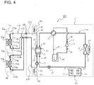
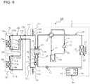
- the air-conditioning apparatus 100 includes an intermediate heat exchanger 20, a refrigerant cycle circuit 110, and a heat-medium cycle circuit 120.
- the intermediate heat exchanger 20 includes a first heat transfer unit 21 in which refrigerant flows, and a second heat transfer unit 22 in which a heat medium different from the refrigerant flows.
- the intermediate heat exchanger 20 is configured to exchange heat between the first heat transfer unit 21 and the second heat transfer unit 22. Examples of the heat medium include water and antifreeze.
- the refrigerant cycle circuit 110 includes a heat source-side heat exchanger 13.
- the heat source-side heat exchanger 13 of the refrigerant cycle circuit 110 is connected with the first heat transfer unit 21 of the intermediate heat exchanger 20 by a pipe.
- Refrigerant circulates inside the refrigerant cycle circuit 110.
- the heat-medium cycle circuit 120 includes a use-side heat exchanger.
- the use-side heat exchanger of the heat-medium cycle circuit 120 is connected with the second heat transfer unit 22 of the intermediate heat exchanger 20 by a pipe.
- the heat medium circulates inside the heat-medium cycle circuit 120. As will be described later, the use-side heat exchanger is accommodated in the indoor unit.
- the air-conditioning apparatus 100 includes, as the indoor unit, the indoor unit 3a and the indoor unit 3b. Accordingly, the air-conditioning apparatus 100 according to Embodiment 1 includes, as the use-side heat exchanger, a use-side heat exchanger 31a accommodated in the indoor unit 3a, and a use-side heat exchanger 31b accommodated in the indoor unit 3b.
- the use-side heat exchanger 31a and the use-side heat exchanger 31b are connected in parallel with the second heat transfer unit 22 of the intermediate heat exchanger 20.
- the refrigerant cycle circuit 110 is configured as described below.
- the refrigerant cycle circuit 110 includes a compressor 11, a flow switching device 12, the heat source-side heat exchanger 13, an expansion device 15, and an accumulator 19.
- the compressor 11, the flow switching device 12, the heat source-side heat exchanger 13, the expansion device 15, the accumulator 19, and the first heat transfer unit 21 of the intermediate heat exchanger 20 are connected by pipes to form the refrigerant cycle circuit 110.
- the compressor 11 sucks and compresses refrigerant into a high-temperature, high-pressure state.
- the compressor 11 is, for example, an inverter compressor whose capacity can be controlled.
- the compressor 11 may have a low-pressure shell structure, or may have a high-pressure shell structure.
- the compressor 11 with a low-pressure shell structure is designed such that a hermetic vessel is filled with low-pressure refrigerant, and the low-pressure refrigerant inside the hermetic vessel is sucked and compressed.
- the compressor 11 with a high-pressure shell structure is designed such that a compression mechanism unit sucks low-pressure refrigerant from a pipe connected with the compression mechanism unit, and a hermetic vessel is filled with the refrigerant compressed by the compression mechanism unit.
- the flow switching device 12 switches between the flow path of refrigerant during cooling operation, and the flow path of refrigerant during heating operation. More specifically, during cooling operation, the flow switching device 12 switches to a flow path as represented by dashed lines in FIG. 1 , that is, a flow path in which the discharge outlet of the compressor 11 is connected with the heat source-side heat exchanger 13 and in which the suction inlet of the compressor 11 is connected with the first heat transfer unit 21 of the intermediate heat exchanger 20.
- the heat source-side heat exchanger 13 functions as a radiator
- the first heat transfer unit 21 of the intermediate heat exchanger 20 functions as an evaporator.
- the radiator is sometimes referred to also as condenser.
- the flow switching device 12 switches to a flow path as represented by solid lines in FIG. 1 , that is, a flow path in which the discharge outlet of the compressor 11 is connected with the first heat transfer unit 21 of the intermediate heat exchanger 20 and in which the suction inlet of the compressor 11 is connected with the heat source-side heat exchanger 13.
- the first heat transfer unit 21 of the intermediate heat exchanger 20 functions as a radiator
- the heat source-side heat exchanger 13 functions as an evaporator.
- the refrigerant flowing in the first heat transfer unit 21 of the intermediate heat exchanger 20 removes heat from the heat medium flowing in the second heat transfer unit 22 of the intermediate heat exchanger 20 to thereby cool the heat medium flowing in the second heat transfer unit 22.
- the refrigerant flowing in the first heat transfer unit 21 of the intermediate heat exchanger 20 rejects heat to the heat medium flowing in the second heat transfer unit 22 of the intermediate heat exchanger 20 to thereby heat the heat medium flowing in the second heat transfer unit 22.
- the flow switching device 12 is, for example, a four-way valve in Embodiment 1, the flow switching device 12 may be, for example, a two-way valve.
- a fan 14 is disposed near the heat source-side heat exchanger 13 to supply outdoor air to the heat source-side heat exchanger 13. Refrigerant flowing in the heat source-side heat exchanger 13 exchanges heat with the outdoor air supplied from the fan 14.
- the expansion device 15 is disposed between the heat source-side heat exchanger 13, and the first heat transfer unit 21 of the intermediate heat exchanger 20 to reduce the pressure of refrigerant exiting the radiator to thereby cause the refrigerant to expand.
- the accumulator 19 is disposed between the suction inlet of the compressor 11, and the evaporator. The accumulator 19 is configured to store excess refrigerant.
- Such excess refrigerant results from, for example, the difference in the rate at which refrigerant circulates in the refrigerant cycle circuit 110 during cooling operation, and the rate at which refrigerant circulates in the refrigerant cycle circuit 110 during heating operation.
- Such excess refrigerant also results from, for example, transient changes in operating state during cooling operation and during heating operation.
- the excess refrigerant stored in the accumulator 19 is at a low pressure.
- a receiver for storing high-pressure excess refrigerant may be provided at the refrigerant cycle circuit 110.
- the heat-medium cycle circuit 120 incudes a pump 23, the use-side heat exchanger 31a, the use-side heat exchanger 31b, a flow control valve 32a, and a flow control valve 32b.
- the pump 23, the use-side heat exchanger 31a, the use-side heat exchanger 31b, the flow control valve 32a, the flow control valve 32b, and the second heat transfer unit 22 of the intermediate heat exchanger 20 are connected by pipes to form the heat-medium cycle circuit 120.
- the pump 23 causes the heat medium inside the heat-medium cycle circuit 120 to circulate. That is, in the heat-medium cycle circuit 120, the pump 23 sucks and pressurizes the heat medium, and discharges the pressurized heat medium.
- the pump 23 is configured such that, for example, the driving frequency of the pump 23 can be varied within a predetermined range to vary the flow rate of the heat medium discharged from the pump 23.
- the pump 23 is disposed near the heat-medium inlet of the intermediate heat exchanger 20. More specifically, a pipe 125 is connected with the heat-medium inlet of the second heat transfer unit 22 of the intermediate heat exchanger 20.
- the pump 23 is provided at the pipe 125. That is, according to Embodiment 1, the heat medium discharged from the pump 23 flows into the second heat transfer unit 22 of the intermediate heat exchanger 20.
- the use-side heat exchanger 31a and the use-side heat exchanger 31b each generate conditioned air that is to be supplied indoors.
- the heat-medium inlet of the use-side heat exchanger 31a is connected with the heat-medium outlet of the second heat transfer unit 22 of the intermediate heat exchanger 20 via a pipe 121, a pipe 122, and a pipe 123a.
- the pipe 121 is a pipe that is accommodated in the heat source unit 1.
- the pipe 122 is a pipe that is disposed outside the heat source unit 1 and the indoor unit 3a.
- the pipe 121 and the pipe 122 are connected with each other by a coupling provided at the heat source unit 1.
- the pipe 123a is a pipe that is accommodated in the indoor unit 3a.
- the pipe 123a and the pipe 122 are connected with each other by a coupling provided at the indoor unit 3a.
- the heat-medium outlet of the use-side heat exchanger 31a is connected with the heat-medium inlet of the second heat transfer unit 22 of the intermediate heat exchanger 20 via the pipe 125, a pipe 126, and a pipe 127a.
- the pipe 125 is a pipe that is accommodated in the heat source unit 1.
- the pipe 126 is a pipe that is disposed outside the heat source unit 1 and the indoor unit 3a.
- the pipe 125 and the pipe 126 are connected with each other by a coupling provided at the heat source unit 1.
- the pipe 127a is a pipe that is accommodated in the indoor unit 3a.
- the pipe 127a and the pipe 126 are connected with each other by a coupling provided at the indoor unit 3a.
- a fan 33a is disposed near the use-side heat exchanger 31a to supply indoor air to the use-side heat exchanger 31a.
- refrigerant cooled in the second heat transfer unit 22 of the intermediate heat exchanger 20 passes through the pipe 121, the pipe 122, and the pipe 123a into the use-side heat exchanger 31a.
- indoor air supplied from the fan 33a passes through the use-side heat exchanger 31a
- the indoor air is cooled by the heat medium flowing in the use-side heat exchanger 31a, and turns into conditioned air.
- the conditioned air then leaves the use-side heat exchanger 31a, and returns indoors.
- the heat medium heated by the indoor air when flowing through the use-side heat exchanger 31a passes through the pipe 127a, the pipe 126, and the pipe 125, and returns to the second heat transfer unit 22 of the intermediate heat exchanger 20.
- refrigerant heated in the second heat transfer unit 22 of the intermediate heat exchanger 20 passes through the pipe 121, the pipe 122, and the pipe 123a into the use-side heat exchanger 31a.
- indoor air supplied from the fan 33a passes through the use-side heat exchanger 31a, the indoor air is heated by the heat medium flowing in the use-side heat exchanger 31a, and turns into conditioned air.
- the conditioned air then leaves the use-side heat exchanger 31a, and returns indoors.
- the heat medium cooled by the indoor air when flowing through the use-side heat exchanger 31a passes through the pipe 127a, the pipe 126, and the pipe 125, and returns to the second heat transfer unit 22 of the intermediate heat exchanger 20.
- the heat-medium inlet of the use-side heat exchanger 31b is connected with the heat-medium outlet of the second heat transfer unit 22 of the intermediate heat exchanger 20 via the pipe 121, the pipe 122, and a pipe 123b.
- the pipe 123b is a pipe that is accommodated in the indoor unit 3b.
- the pipe 123b and the pipe 122 are connected with each other by a coupling provided at the indoor unit 3b.
- the pipe 123b and the pipe 123a are connected in parallel with the pipe 122.
- the heat-medium outlet of the use-side heat exchanger 31b is connected with the heat-medium inlet of the second heat transfer unit 22 of the intermediate heat exchanger 20 via the pipe 125, the pipe 126, and a pipe 127b.
- the pipe 127b is a pipe that is accommodated in the indoor unit 3b.
- the pipe 127b and the pipe 126 are connected with each other by a coupling provided at the indoor unit 3b.
- the pipe 127b and the pipe 127a are connected in parallel with the pipe 126.
- a fan 33b is disposed near the use-side heat exchanger 31b to supply indoor air to the use-side heat exchanger 31b.
- refrigerant cooled in the second heat transfer unit 22 of the intermediate heat exchanger 20 passes through the pipe 121, the pipe 122, and the pipe 123b into the use-side heat exchanger 31b.
- indoor air supplied from the fan 33b passes through the use-side heat exchanger 31b, the indoor air is cooled by the heat medium flowing in the use-side heat exchanger 31b, and turns into conditioned air.
- the conditioned air then leaves the use-side heat exchanger 31b, and returns indoors.
- the heat medium heated by the indoor air when flowing through the use-side heat exchanger 31b passes through the pipe 127b, the pipe 126, and the pipe 125, and returns to the second heat transfer unit 22 of the intermediate heat exchanger 20.
- refrigerant heated in the second heat transfer unit 22 of the intermediate heat exchanger 20 passes through the pipe 121, the pipe 122, and the pipe 123b into the use-side heat exchanger 31b.
- indoor air supplied from the fan 33b passes through the use-side heat exchanger 31b, the indoor air is heated by the heat medium flowing in the use-side heat exchanger 31b, and turns into conditioned air.
- the conditioned air then leaves the use-side heat exchanger 31b, and returns indoors.
- the heat medium cooled by the indoor air when flowing through the use-side heat exchanger 31b passes through the pipe 127b, the pipe 126, and the pipe 125, and returns to the second heat transfer unit 22 of the intermediate heat exchanger 20.
- the flow control valve 32a controls the flow rate of the heat medium entering the use-side heat exchanger 31a.
- the flow control valve 32a is, for example, a two-way valve whose opening degree can be adjusted.
- the flow control valve 32a is provided at the pipe 123a, which is connected with the heat-medium inlet of the use-side heat exchanger 31a.
- the flow control valve 32a may be provided at the pipe 127a, which is connected with the heat-medium outlet of the use-side heat exchanger 31a.
- the flow control valve 32b controls the flow rate of the heat medium entering the use-side heat exchanger 31b.
- the flow control valve 32b is, for example, a two-way valve whose opening degree can be adjusted.
- the flow control valve 32b is provided at the pipe 123b, which is connected with the heat-medium inlet of the use-side heat exchanger 31b.
- the flow control valve 32a may be provided at the pipe 127b, which is connected with the heat-medium outlet of the use-side heat exchanger 31b.
- the air-conditioning apparatus 100 includes a plurality of sets of a use-side heat exchanger and a flow control valve, which is a valve configured to control the flow rate of the heat medium entering the use-side heat exchanger. These sets are connected in parallel with each other in the heat-medium cycle circuit 120.
- the air-conditioning apparatus 100 includes a supply mechanism 60, and a discharge mechanism 65.
- the supply mechanism 60 is provided at the heat-medium cycle circuit 120.
- the supply mechanism 60 is used in charging the heat medium into the heat-medium cycle circuit 120 during, for example, installation of the air-conditioning apparatus 100.
- the supply mechanism 60 includes a supply pipe 61, and a supply valve 62.
- the supply pipe 61 is connected with the heat-medium cycle circuit 120.
- the supply pipe 61 is connected to a heat-medium supply source when the heat medium is to be charged into the heat-medium cycle circuit 120. For example, if the heat medium is water, the supply pipe 61 is connected to a water supply.
- the supply valve 62 is, for example, an open/close valve provided at the supply pipe 61 and capable of opening and closing the flow path inside the supply pipe 61. That is, when the supply valve 62 opens, the heat medium is charged into the heat-medium cycle circuit 120 through the supply pipe 61. When the supply valve 62 closes, the charging of the heat medium into the heat-medium cycle circuit 120 ends.
- the pipe 125 is connected with the heat-medium inlet of the second heat transfer unit 22 of the intermediate heat exchanger 20.
- the supply mechanism 60 is provided at the pipe 125. More specifically, according to Embodiment 1, the supply mechanism 60 is provided at the pipe 125 at a location near the suction side of the pump 23.
- the discharge mechanism 65 is provided at the heat-medium cycle circuit 120 to discharge air present inside the heat-medium cycle circuit 120 to the outside of the heat-medium cycle circuit 120.
- the discharge mechanism 65 includes a discharge pipe 66, and a discharge valve 67.
- the discharge pipe 66 is connected with the heat-medium cycle circuit 120.
- the discharge valve 67 is provided at the discharge pipe 66.
- the discharge valve 67 is capable of discharging air flowing into the discharge pipe 66 from inside the heat-medium cycle circuit 120. That is, when the discharge valve 67 opens, air present inside the heat-medium cycle circuit 120 is discharged to the outside of the heat-medium cycle circuit 120 through the discharge pipe 66. When the discharge valve 67 closes, the discharge of air from the heat-medium cycle circuit 120 ends.
- the discharge mechanism 65 is configured to, when the discharge valve 67 is open, discharge air present inside the heat-medium cycle circuit 120 to the outside of the heat-medium cycle circuit 120.
- the pipe 121 is connected with the heat-medium outlet of the second heat transfer unit 22 of the intermediate heat exchanger 20. According to Embodiment 1, the discharge mechanism 65 is provided at the pipe 121.
- the above-mentioned components of the air-conditioning apparatus 100 are accommodated in the heat source unit 1, the indoor unit 3a, or the indoor unit 3b.
- the components of the refrigerant cycle circuit 110 are accommodated in the heat source unit 1. More specifically, the compressor 11, the flow switching device 12, the heat source-side heat exchanger 13, the expansion device 15, and the accumulator 19 are accommodated in the heat source unit 1. Further, the fan 14, the intermediate heat exchanger 20, the supply mechanism 60, and the discharge mechanism 65 are accommodated in the heat source unit 1.
- the pump 23 is accommodated in the heat source unit 1.
- the components of the heat-medium cycle circuit 120 other than the pump 23 are accommodated in the indoor unit 3a or the indoor unit 3b.
- the use-side heat exchanger 31a and the flow control valve 32a are accommodated in the indoor unit 3a.
- the use-side heat exchanger 31b and the flow control valve 32b are accommodated in the indoor unit 3b.
- the fan 33a is accommodated in the indoor unit 3a, and the fan 33b is accommodated in the indoor unit 3b.
- the air-conditioning apparatus 100 includes various sensors, and a controller 50 configured to, based on values detected by these sensors, control the components of the air-conditioning apparatus 100.
- the air-conditioning apparatus 100 includes the following sensors provided at the heat source unit 1: a first temperature sensor 24, a second temperature sensor 25, a temperature sensor 41, a temperature sensor 42, a temperature sensor 43, a temperature sensor 44, a temperature sensor 45, a pressure sensor 46, and a pressure sensor 47.
- the first temperature sensor 24 is, for example, a thermistor, and detects the temperature of the heat medium that enters the second heat transfer unit 22 of the intermediate heat exchanger 20.
- the second temperature sensor 25 is, for example, a thermistor, and detects the temperature of the heat medium that exits the second heat transfer unit 22 of the intermediate heat exchanger 20.
- the temperature sensor 41 is, for example, a thermistor, and detects the temperature of refrigerant that is discharged from the compressor 11.
- the temperature sensor 42 is, for example, a thermistor, and detects the temperature of refrigerant that is sucked into the compressor 11.
- the temperature sensor 43 is, for example, a thermistor, and detects the temperature of outdoor air that is supplied to the heat source-side heat exchanger 13.
- the temperature sensor 44 is, for example, a thermistor.
- the temperature sensor 44 is configured to, during cooling operation, detect the temperature of refrigerant that exits the first heat transfer unit 21 of the intermediate heat exchanger 20.
- the temperature sensor 44 is configured to, during heating operation, detect the temperature of refrigerant that enters the first heat transfer unit 21 of the intermediate heat exchanger 20.
- the temperature sensor 45 is, for example, a thermistor.
- the temperature sensor 45 is configured to, during cooling operation, detect the temperature of refrigerant that enters the first heat transfer unit 21 of the intermediate heat exchanger 20.
- the temperature sensor 45 is configured to, during heating operation, detect the temperature of refrigerant that exits the first heat transfer unit 21 of the intermediate heat exchanger 20.
- the pressure sensor 46 detects the pressure of refrigerant that is discharged from the compressor 11.
- the pressure sensor 47 detects the temperature of refrigerant that is sucked into the compressor 11.
- the air-conditioning apparatus 100 includes a temperature sensor 34a and a temperature sensor 35a that are provided at the indoor unit 3a.
- the temperature sensor 34a is, for example, a thermistor, and detects the temperature of the heat medium that enters the use-side heat exchanger 31a.
- the temperature sensor 35a is, for example, a thermistor, and detects the temperature of the heat medium that exits the use-side heat exchanger 31a.
- the air-conditioning apparatus 100 includes a temperature sensor 34b and a temperature sensor 35b that are provided at the indoor unit 3b.
- the temperature sensor 34b is, for example, a thermistor, and detects the temperature of the heat medium that enters the use-side heat exchanger 31b.
- the temperature sensor 35b is, for example, a thermistor, and detects the temperature of the heat medium that exits the use-side heat exchanger 31b.
- the controller 50 is configured to, based on information such as values detected by the various sensors provided at the air-conditioning apparatus 100, control the following features: activation and deactivation of the compressor 11; the driving frequency of the compressor 11; the flow path of the flow switching device 12; activation and deactivation of the fan 14; the rotation speed of the fan 14 during driving of the fan 14; the opening degree of the expansion device 15; activation and deactivation of the pump 23; the driving frequency of the pump 23; the opening degree of the flow control valve 32a; the opening degree of the flow control valve 32b; activation and deactivation of the fan 33a; the rotation speed of the fan 33a during driving of the fan 33a; activation and deactivation of the fan 33b; the rotation speed of the fan 33b during driving of the fan 33b; the opening degree of the supply valve 62; and the opening degree of the discharge valve 67.
- the controller 50 may be a dedicated piece of hardware, or may be a central processing unit (CPU) that executes a program stored in a memory.
- the CPU is also referred to as a central processing unit, a processing unit, a computing unit, a microprocessor, a microcomputer, or a processor.
- the controller 50 is a dedicated piece of hardware, the controller 50 corresponds to, for example, a single circuit, a composite circuit, an application specific integrated circuit (ASIC), a field-programmable gate array (FPGA), or a combination thereof.
- the functional units to be implemented by the controller 50 may be each implemented by an individual piece of hardware, or the functional units may be implemented by a single piece of hardware.
- each function to be executed by the controller 50 is implemented by software, firmware, or a combination of software and firmware.
- the software and the firmware are each described as a program, and stored in a memory. As the CPU reads and executes the program stored in the memory, each function of the controller 50 is implemented.
- the memory is, for example, a non-volatile or volatile semiconductor memory, such as a RAM, a ROM, a flash memory, an EPROM, or an EEPROM.
- the functions of the controller 50 may be partially implemented by dedicated hardware, and may be partially implemented by software or firmware. Although the controller 50 is accommodated in the heat source unit 1 in Embodiment 1, the controller 50 may be accommodated in the indoor unit 3a or the indoor unit 3b. The controller 50 may be divided into separate parts that are accommodated in at least two of the heat source unit 1, the indoor unit 3a, and the indoor unit 3b.
- the controller 50 includes the following functional units: an input unit 51, a receiving unit 52, a control unit 53, and an operation-mode switching unit 54.
- the input unit 51 is a functional unit configured to receive input of a command from a remote control or other device (not illustrated). For example, the input unit 51 receives, from a remote control or other device (not illustrated), an input of an operation mode that is being required for the air-conditioning apparatus 100.
- the air-conditioning apparatus 100 according to Embodiment 1 includes a cooling operation mode, a heating operation mode, and an air discharge operation mode. Further, as will be described later, the air discharge operation mode of the air-conditioning apparatus 100 according to Embodiment 1 includes a first operation mode, and a second operation mode performed after the first operation mode.
- the receiving unit 52 is a functional unit configured to receive values detected by the various sensors provided at the air-conditioning apparatus 100.
- the control unit 53 is a functional unit configured to, based on values detected by the various sensors provided at the air-conditioning apparatus 100 and based on a command or other information input to the input unit 51, control the following features: activation and deactivation of the compressor 11; the driving frequency of the compressor 11; the flow path of the flow switching device 12; activation and deactivation of the fan 14; the rotation speed of the fan 14 during driving of the fan 14; the opening degree of the expansion device 15; activation and deactivation of the pump 23; the driving frequency of the pump 23; the opening degree of the flow control valve 32a; the opening degree of the flow control valve 32b; activation and deactivation of the fan 33a; the rotation speed of the fan 33a during driving of the fan 33a; activation and deactivation of the fan 33b; the rotation speed of the fan 33b during driving of the fan 33b; the opening degree of the supply valve 62; and the opening degree of the discharge valve 67.
- the operation-mode switching unit 54 is a functional unit configured to, during operation of the air-conditioning apparatus 100 in the air discharge operation mode, determine whether to switch from the first operation mode to the second operation mode. That is, the controller 50 according to Embodiment 1 can be said to be a controller that is also capable of switching from the first operation mode to the second operation mode during operation in the air discharge operation mode.
- the cooling operation mode is an operation mode in which at least one of the indoor unit 3a and the indoor unit 3b performs indoor cooling. That is, the cooling operation mode is an operation mode in which the air-conditioning apparatus 100 performs a cooling operation.
- the following describes a case in which both the indoor unit 3a and the indoor unit 3b perform indoor cooling.
- the compressor 11 sucks and compresses low-temperature, low-pressure gas refrigerant, and discharges the resulting refrigerant as high-temperature, high-pressure gas refrigerant.
- the high-temperature, high-pressure gas refrigerant discharged from the compressor 11 passes through the flow switching device 12 into the heat source-side heat exchanger 13 that functions as a radiator.
- the high-temperature, high-pressure gas refrigerant is cooled by outdoor air supplied from the fan 14, and turns into liquid refrigerant at a medium temperature and high pressure, which then exits the heat source-side heat exchanger 13.
- refrigerant exiting the heat source-side heat exchanger 13 at this time is two-phase gas-liquid refrigerant at a medium temperature and high pressure.
- the medium-temperature, high-pressure refrigerant exiting the heat source-side heat exchanger 13 flows into the expansion device 15.
- the medium-temperature, high-pressure refrigerant entering the expansion device 15 undergoes a pressure reduction in the expansion device 15 and turns into low-temperature, low-pressure two-phase gas-liquid refrigerant, which then exits the expansion device 15. After exiting the expansion device 15, the low-temperature, low-pressure two-phase gas-liquid refrigerant flows into the first heat transfer unit 21 of the intermediate heat exchanger 20 that functions as an evaporator.
- the low-temperature, low-pressure two-phase gas-liquid refrigerant Upon entering the first heat transfer unit 21 of the intermediate heat exchanger 20, the low-temperature, low-pressure two-phase gas-liquid refrigerant is heated by the heat medium flowing in the second heat transfer unit 22 of the intermediate heat exchanger 20, and turns into low-temperature, low-pressure gas refrigerant, which then exits the first heat transfer unit 21 of the intermediate heat exchanger 20.
- refrigerant exiting the first heat transfer unit 21 of the intermediate heat exchanger 20 at this time is two-phase gas-liquid refrigerant at a low temperature and low pressure.
- the low-temperature, low-pressure refrigerant After exiting the first heat transfer unit 21 of the intermediate heat exchanger 20, the low-temperature, low-pressure refrigerant passes through the flow switching device 12 into the accumulator 19. Of the low-temperature, low-pressure refrigerant entering the accumulator 19, low-temperature, low-pressure gas refrigerant is sucked into the compressor 11 again.
- the heat medium discharged from the pump 23 flows into the second heat transfer unit 22 of the intermediate heat exchanger 20.
- the heat medium Upon entering the second heat transfer unit 22 of the intermediate heat exchanger 20, the heat medium is cooled by the refrigerant flowing in the first heat transfer unit 21 of the intermediate heat exchanger 20.
- the resulting heat medium then exits the second heat transfer unit 22 of the intermediate heat exchanger 20.
- the heat medium After exiting the second heat transfer unit 22 of the intermediate heat exchanger 20, the heat medium passes through the pipe 121 into the pipe 122.
- a portion of the heat medium entering the pipe 122 passes through the pipe 123a and the flow control valve 32a into the use-side heat exchanger 31a.
- the remainder of the refrigerant entering the pipe 122 passes through the pipe 123b and the flow control valve 32b into the use-side heat exchanger 31b.
- the heat medium entering the use-side heat exchanger 31a is heated as the heat medium cools indoor air supplied from the fan 33a.
- the resulting heat medium then exits the use-side heat exchanger 31a.
- the heat medium passes through the pipe 127a into the pipe 126.
- the heat medium entering the use-side heat exchanger 31b is heated as the heat medium cools indoor air supplied from the fan 33b.
- the resulting heat medium then exits the use-side heat exchanger 31b.
- the heat medium passes through the pipe 127b into the pipe 126, where the heat medium combines with the heat medium entering the pipe 126 from the use-side heat exchanger 31a.
- the heat medium entering the pipe 126 then passes through the pipe 125, and is sucked into the pump 23 again.
- the control unit 53 of the controller 50 is configured to, based on a temperature detected by the first temperature sensor 24 and a temperature detected by the second temperature sensor 25, perform a control to prevent freezing of the heat medium.
- control unit 53 causes the driving frequency of the compressor 11 to decrease to thereby increase the temperature of refrigerant entering the first heat transfer unit 21 of the intermediate heat exchanger 20.
- the heating operation mode is an operation mode in which at least one of the indoor unit 3a and the indoor unit 3b performs indoor heating. That is, the heating operation mode is an operation mode in which the air-conditioning apparatus 100 performs a heating operation.
- the following describes a case in which both the indoor unit 3a and the indoor unit 3b perform indoor heating.
- the compressor 11 sucks and compresses low-temperature, low-pressure gas refrigerant, and discharges the resulting refrigerant as high-temperature, high-pressure gas refrigerant.
- the high-temperature, high-pressure gas refrigerant discharged from the compressor 11 passes through the flow switching device 12 into the first heat transfer unit 21 of the intermediate heat exchanger 20 that functions as a radiator.
- the high-temperature, high-pressure gas refrigerant Upon entering the first heat transfer unit 21 of the intermediate heat exchanger 20, the high-temperature, high-pressure gas refrigerant is cooled by the heat medium flowing in the second heat transfer unit 22 of the intermediate heat exchanger 20, and turns into medium-temperature, high-pressure liquid refrigerant, which then exits the first heat transfer unit 21 of the intermediate heat exchanger 20.
- the medium-temperature, high-pressure refrigerant exiting the first heat transfer unit 21 of the intermediate heat exchanger 20 flows into the expansion device 15.
- the medium-temperature, high-pressure refrigerant entering the expansion device 15 undergoes a pressure reduction in the expansion device 15 and turns into low-temperature, low-pressure two-phase gas-liquid refrigerant, which then exits the expansion device 15.
- the low-temperature, low-pressure two-phase gas-liquid refrigerant flows into the heat source-side heat exchanger 13 that functions as an evaporator.
- the low-temperature, low-pressure two-phase gas-liquid refrigerant is heated by outdoor air supplied from the fan 14, and turns into gas refrigerant at a low temperature and low pressure, which then exits the heat source-side heat exchanger 13.
- refrigerant exiting the heat source-side heat exchanger 13 at this time is two-phase gas-liquid refrigerant at a low temperature and low pressure.
- the low-temperature, low-pressure refrigerant After exiting the heat source-side heat exchanger 13, the low-temperature, low-pressure refrigerant passes through the flow switching device 12 into the accumulator 19. Of the low-temperature, low-pressure refrigerant entering the accumulator 19, low-temperature, low-pressure gas refrigerant is sucked into the compressor 11 again.
- the heat medium discharged from the pump 23 flows into the second heat transfer unit 22 of the intermediate heat exchanger 20.
- the heat medium Upon entering the second heat transfer unit 22 of the intermediate heat exchanger 20, the heat medium is heated by the refrigerant flowing in the first heat transfer unit 21 of the intermediate heat exchanger 20.
- the resulting heat medium then exits the second heat transfer unit 22 of the intermediate heat exchanger 20.
- the heat medium After exiting the second heat transfer unit 22 of the intermediate heat exchanger 20, the heat medium passes through the pipe 121 into the pipe 122.
- a portion of the heat medium entering the pipe 122 passes through the pipe 123a and the flow control valve 32a into the use-side heat exchanger 31a.
- the remainder of the refrigerant entering the pipe 122 passes through the pipe 123b and the flow control valve 32b into the use-side heat exchanger 31b.
- the heat medium entering the use-side heat exchanger 31a is cooled as the heat medium heats indoor air supplied from the fan 33 a.
- the resulting heat medium then exits the use-side heat exchanger 31a.
- the heat medium passes through the pipe 127a into the pipe 126.
- the heat medium entering the use-side heat exchanger 31b is cooled as the heat medium heats indoor air supplied from the fan 33b.
- the resulting heat medium then exits the use-side heat exchanger 31b.
- the heat medium passes through the pipe 127b into the pipe 126, where the heat medium combines with the heat medium entering the pipe 126 from the use-side heat exchanger 31a.
- the heat medium entering the pipe 126 then passes through the pipe 125, and is sucked into the pump 23 again.
- the air discharge operation mode is an operation mode in which air present inside the heat-medium cycle circuit 120 is discharged to the outside of the heat-medium cycle circuit 120.
- the air discharge operation mode of the air-conditioning apparatus 100 includes a first operation mode, and a second operation mode performed after the first operation mode.
- the first operation mode is an operation mode in which a first process described later is performed.
- the second operation mode is an operation mode in which a second process described later is performed. Reference is now made to FIG. 2 to describe a specific procedure for the air discharge operation mode.
- FIG. 2 is a flowchart illustrating the air discharging operation mode of the air-conditioning apparatus according to Embodiment 1. That is, FIG. 2 is a flowchart illustrating how the air-conditioning apparatus 100 according to Embodiment 1 operates in the air discharge operation mode.
- the controller 50 of the air-conditioning apparatus 100 performs a first process at step S1. In other words, the controller 50 sets the operation mode of the air-conditioning apparatus 100 to the first operation mode.
- the first process is a process of, with the heat source-side heat exchanger 13 functioning as a radiator, and with the first heat transfer unit 21 of the intermediate heat exchanger 20 functioning as an evaporator, circulating refrigerant in the refrigerant cycle circuit 110. Further, the first process is a process of, with the discharge valve of the discharge mechanism 65 being closed, circulating the heat medium in the heat-medium cycle circuit 120.
- the first operation mode is an operation mode in which, with the heat source-side heat exchanger 13 functioning as a radiator, and with the first heat transfer unit 21 of the intermediate heat exchanger 20 functioning as an evaporator, refrigerant circulates in the refrigerant cycle circuit 110. Further, the first operation mode is an operation mode in which, with the discharge valve 67 of the discharge mechanism 65 being closed, the heat medium circulates in the heat-medium cycle circuit 120.
- the operation of the air-conditioning apparatus 100 in the first operation mode is basically similar to the operation of the air-conditioning apparatus 100 in the cooling operation mode.
- the control unit 53 of the controller 50 switches the flow path of the flow switching device 12 to the same flow path as that during cooling operation. Further, the control unit 53 opens the flow control valve 32a and the flow control valve 32b. In this state, the control unit 53 activates the compressor 11, the fan 14, and the pump 23. Further, the control unit 53 controls the opening degree of the expansion device 15 such that refrigerant exiting the heat source-side heat exchanger 13 undergoes a decrease in pressure and expands.
- the heat medium flowing in the second heat transfer unit 22 of the intermediate heat exchanger 20 is cooled by the refrigerant flowing in the first heat transfer unit 21 of the intermediate heat exchanger 20.
- the cooled heat medium then circulates in the heat-medium cycle circuit 120.
- the lower the temperature of the heat medium the greater the rate at which air dissolves into the heat medium. Accordingly, by circulating the cooled heat medium in the heat-medium cycle circuit 120 as described above, an air parcel present inside the heat-medium cycle circuit 120 can be dissolved into the heat medium.
- the heat medium circulating in the heat-medium cycle circuit 120 is heated by indoor air supplied by each of the fan 33a and the fan 33b. This causes the temperature of the heat medium to increase. The increase in the temperature of the heat medium results in a decrease in the rate at which an air parcel present inside the heat-medium cycle circuit 120 is dissolved into the heat medium. For this reason, in the first operation mode of the air-conditioning apparatus 100 according to Embodiment 1, the control unit 53 deactivates the fan 33a and the fan 33b. This helps to increase the rate at which an air parcel present inside the heat-medium cycle circuit 120 is dissolved into the heat medium. As a result, the air parcel inside the heat-medium cycle circuit 120 can be efficiently dissolved into the heat medium.
- the supply valve 62 of the supply mechanism 60 may be set at any opening degree. In one example, if the first process is to be performed when charging of the heat medium into the heat-medium cycle circuit 120 is not yet complete, the first process may be performed with the supply valve 62 of the supply mechanism 60 being open. In another example, if the first process is to be performed when charging of the heat medium into the heat-medium cycle circuit 120 is complete, the first process may be performed with the supply valve 62 of the supply mechanism 60 being closed.
- Step S2 is a step of determining whether to switch from the first process to the second process. That is, at step S2, the operation-mode switching unit 54 of the controller 50 determines whether to switch from the first operation mode to the second operation mode. The operation-mode switching unit 54 returns to step S1 until an air parcel present inside the heat-medium cycle circuit 120 is assumed to have completely dissolved into the heat medium. Thus, the first process is continued. In other words, the first operation mode is maintained. Once an air parcel present inside the heat-medium cycle circuit 120 is assumed to have completely dissolved into the heat medium, the operation-mode switching unit 54 proceeds to step S3. That is, the operation-mode switching unit 54 determines to switch from the first operation mode to the second operation mode. According to Embodiment 1, whether to switch from the first operation mode to the second operation mode is determined as described below.
- FIG. 3 illustrates how the operation-mode switching unit of the controller included in the air-conditioning apparatus according to Embodiment 1 determines whether to switch operation modes.
- the horizontal axis represents the time for which the air-conditioning apparatus 100 is operated in the first operation mode.
- ⁇ T taken along the vertical axis represents a temperature difference obtained by subtracting a temperature detected by the second temperature sensor 25 from a temperature detected by the first temperature sensor 24. That is, ⁇ T represents a temperature difference obtained by subtracting the temperature of the heat medium exiting the second heat transfer unit 22 of the intermediate heat exchanger 20 from the temperature of the heat medium entering the second heat transfer unit 22 of the intermediate heat exchanger 20.
- the heat medium has not yet been cooled in the second heat transfer unit 22 of the intermediate heat exchanger 20, and thus ⁇ T is close to zero degrees Celsius.
- the air-conditioning apparatus 100 continues to be operated in the first operation mode, the heat medium is cooled progressively in the second heat transfer unit 22 of the intermediate heat exchanger 20.
- the temperature of the heat medium exiting the second heat transfer unit 22 of the intermediate heat exchanger 20 decreases progressively, and thus the value of ⁇ T increases progressively.
- the fan 33a and the fan 33b are deactivated to ensure that the heat medium is not heated by indoor air supplied from each of the fan 33a and the fan 33b.
- the temperature of the heat medium entering the second heat transfer unit 22 of the intermediate heat exchanger 20 decreases progressively. Meanwhile, as the temperature of the heat medium flowing in the second heat transfer unit 22 of the intermediate heat exchanger 20 approaches the temperature of the refrigerant flowing in the first heat transfer unit 21 of the intermediate heat exchanger 20, the decrease per unit time of the temperature of the heat medium exiting the second heat transfer unit 22 of the intermediate heat exchanger 20 decreases.
- ⁇ T increases first and then decreases progressively, and the change of ⁇ T per unit time eventually becomes less than or equal to a predetermined value.
- ⁇ T decreases progressively, and ⁇ T eventually becomes substantially constant. This is indicative of a state in which a sufficiently cooled heat medium is circulating in the heat-medium cycle circuit 120, that is, a state in which the temperature of the heat medium inside the heat-medium cycle circuit 120 has become substantially uniform. Therefore, this is indicative of a state in which an air parcel present inside the heat-medium cycle circuit 120 is assumed to have completely dissolved into the heat medium.
- the operation-mode switching unit 54 determines to switch from the first operation mode to the second operation mode, after ⁇ T decreases and the change of ⁇ T per unit time becomes less than or equal to a predetermined value.
- the controller 50 switches from the first operation mode to the second operation mode after ⁇ T decreases and the change of ⁇ T per unit time becomes less than or equal to a predetermined value.
- the second process is performed.
- the controller 50 changes the operation mode of the air-conditioning apparatus 100 to the second operation mode.
- the second process is a process of, with the heat source-side heat exchanger 13 functioning as an evaporator, and with the first heat transfer unit 21 of the intermediate heat exchanger 20 functioning as a radiator, circulating refrigerant in the refrigerant cycle circuit 110. Further, the second process is a process of, with the discharge valve 67 of the discharge mechanism 65 being open, circulating the heat medium in the heat-medium cycle circuit 120.
- the second operation mode is an operation mode in which, with the heat source-side heat exchanger 13 functioning as an evaporator, and with the first heat transfer unit 21 of the intermediate heat exchanger 20 functioning as a radiator, refrigerant circulates in the refrigerant cycle circuit 110. Further, the second operation mode is an operation mode in which, with the discharge valve 67 of the discharge mechanism 65 being open, the heat medium circulates in the heat-medium cycle circuit 120.
- the operation of the air-conditioning apparatus 100 in the second operation mode is basically similar to the operation of the air-conditioning apparatus 100 in the heating operation mode, except that the discharge valve 67 of the discharge mechanism 65 is open.
- the control unit 53 of the controller 50 switches the flow path of the flow switching device 12 to the same flow path as that during heating operation. Further, the control unit 53 opens the flow control valve 32a and the flow control valve 32b. In this state, the control unit 53 activates the compressor 11, the fan 14, and the pump 23. Further, the control unit 53 controls the opening degree of the expansion device 15 such that refrigerant exiting the first heat transfer unit 21 of the intermediate heat exchanger 20 undergoes a decrease in pressure and expands.
- the heat medium flowing in the second heat transfer unit 22 of the intermediate heat exchanger 20 is heated by the refrigerant flowing in the first heat transfer unit 21 of the intermediate heat exchanger 20.
- the heated heat medium then circulates in the heat-medium cycle circuit 120.
- the higher the temperature of the heat medium the lower the rate at which air dissolves into the heat medium.
- air that has been dissolved in the heat medium can be released from the heat medium, and the air released from the heat medium can be discharged through the discharge mechanism 65 to the outside of the heat-medium cycle circuit 120.
- the air discharge operation mode according to Embodiment 1 allows for greater discharge of air present inside the heat-medium cycle circuit 120 to the outside of the heat-medium cycle circuit 120 than is conventionally possible.
- the heat medium circulating in the heat-medium cycle circuit 120 is cooled by indoor air supplied by each of the fan 33a and the fan 33b. This causes the temperature of the heat medium to decrease. The decrease in the temperature of the heat medium results in a decrease in the rate at which air dissolved in the heat medium is released from the heat medium. For this reason, in the second operation mode of the air-conditioning apparatus 100 according to Embodiment 1, the control unit 53 deactivates the fan 33a and the fan 33b. This helps to increase the rate at which air dissolved in the heat medium is released from the heat medium, leading to reduced operating time in the second operation mode.
- the supply valve 62 of the supply mechanism 60 may be at any opening degree.
- the second process may be performed with the supply valve 62 of the supply mechanism 60 being closed.
- the second process may be performed with the supply valve 62 of the supply mechanism 60 being open and with the heat medium being charged into the heat-medium cycle circuit 120.
- Step S4 is a step of determining whether to end the second process. According to Embodiment 1, until a predetermined time elapses after the start of the second process, the controller 50 determines not to end the second process, and returns to step S3. Upon elapse of the predetermined time after the start of the second process, the controller 50 determines to end the second process. As a result, the operation of the air-conditioning apparatus 100 in the air discharge operation mode ends.
- the controller 50 automatically performs all of the following operations: the first process; the determination of whether to switch from the first process to the second process; the switching from the first process to the second process; the second process; and the determination of whether to end the second process.
- this is not intended to be limiting. Alternatively, at least one of these operations may be performed manually by the operator.
- the air-conditioning apparatus 100 includes the intermediate heat exchanger 20, the refrigerant cycle circuit 110, the heat-medium cycle circuit 120, and the discharge mechanism 65.
- the intermediate heat exchanger 20 includes the first heat transfer unit 21 in which refrigerant flows, and the second heat transfer unit 22 in which a heat medium different from the refrigerant flows.
- the intermediate heat exchanger 20 is configured to exchange heat between the first heat transfer unit 21 and the second heat transfer unit 22.
- the refrigerant cycle circuit 110 includes the heat source-side heat exchanger 13.
- the heat source-side heat exchanger 13 is connected with the first heat transfer unit 21 by a pipe.
- the refrigerant cycle circuit 110 is configured to allow the refrigerant to circulate inside the refrigerant cycle circuit 110.
- the heat-medium cycle circuit 120 includes a use-side heat exchanger.
- the use-side heat exchanger is connected with the second heat transfer unit 22 by a pipe.
- the heat-medium cycle circuit 120 is configured to allow the heat medium to circulate inside the heat-medium cycle circuit 120.
- the discharge mechanism 65 is provided at the heat-medium cycle circuit 120, and includes the discharge valve 67.
- the discharge mechanism 65 is configured to, when the discharge valve 67 is open, discharge air present inside the heat-medium cycle circuit 120 to the outside of the heat-medium cycle circuit 120.
- the air-conditioning apparatus 100 is configured to execute the air discharge operation mode in which the air present inside the heat-medium cycle circuit 120 is discharged to the outside of the heat-medium cycle circuit 120.
- the air discharge operation mode includes the first operation mode, and the second operation mode performed after the first operation mode.
- the first operation mode is an operation mode in which, with the heat source-side heat exchanger 13 functioning as a radiator, and with the first heat transfer unit 21 of the intermediate heat exchanger 20 functioning as an evaporator, the refrigerant circulates in the refrigerant cycle circuit 110. Further, the first operation mode is an operation mode in which, with the discharge valve 67 of the discharge mechanism 65 being closed, the heat medium circulates in the heat-medium cycle circuit 120.
- the second operation mode is an operation mode in which, with the heat source-side heat exchanger 13 functioning as an evaporator, and with the first heat transfer unit 21 of the intermediate heat exchanger 20 functioning as a radiator, the refrigerant circulates in the refrigerant cycle circuit 110. Further, the second operation mode is an operation mode in which, with the discharge valve 67 of the discharge mechanism 65 being open, the heat medium circulates in the heat-medium cycle circuit 120.
- the air-conditioning apparatus 100 configured as mentioned above, an air parcel present inside the heat-medium cycle circuit 120, and air that has been dissolved in the heat medium since the charging of the heat medium into the heat-medium cycle circuit 120 can be both discharged to the outside of the heat-medium cycle circuit 120. Therefore, the air-conditioning apparatus 100 configured as described above allows for greater discharge of air present inside the heat-medium cycle circuit 120 to the outside of the heat-medium cycle circuit 120 than is conventionally possible.
- An air discharge method for the air-conditioning apparatus 100 according to Embodiment 1 is an air discharge method for the air-conditioning apparatus 100 that includes the intermediate heat exchanger 20, the refrigerant cycle circuit 110, the heat-medium cycle circuit 120, and the discharge mechanism 65.
- the intermediate heat exchanger 20 includes the first heat transfer unit 21 in which refrigerant flows, and the second heat transfer unit 22 in which a heat medium different from the refrigerant flows.
- the intermediate heat exchanger 20 is configured to exchange heat between the first heat transfer unit 21 and the second heat transfer unit 22.
- the refrigerant cycle circuit 110 includes the heat source-side heat exchanger 13.
- the heat source-side heat exchanger 13 is connected with the first heat transfer unit 21 by a pipe.
- the refrigerant cycle circuit 110 is configured to allow the refrigerant to circulate inside the refrigerant cycle circuit 110.
- the heat-medium cycle circuit 120 includes a use-side heat exchanger. The use-side heat exchanger is connected with the second heat transfer unit 22 by a pipe.
- the heat-medium cycle circuit 120 is configured to allow the heat medium to circulate inside the heat-medium cycle circuit 120.
- the discharge mechanism 65 is provided at the heat-medium cycle circuit 120, and includes the discharge valve 67. The discharge mechanism 65 is configured to, when the discharge valve 67 is open, discharge air present inside the heat-medium cycle circuit 120 to the outside of the heat-medium cycle circuit 120.
- the air discharge method for the air-conditioning apparatus 100 is a method for discharging the air present inside the heat-medium cycle circuit 120 to the outside of the heat-medium cycle circuit 120.
- the air discharge method includes a first process, and a second process performed after the first process.
- the first process is a process of, with the heat source-side heat exchanger 13 functioning as a radiator, and with the first heat transfer unit 21 of the intermediate heat exchanger 20 functioning as an evaporator, circulating refrigerant in the refrigerant cycle circuit 110.
- the first process is a process of, with the discharge valve of the discharge mechanism 65 being closed, circulating the heat medium in the heat-medium cycle circuit 120.
- the second process is a process of, with the heat source-side heat exchanger 13 functioning as an evaporator, and with the first heat transfer unit 21 of the intermediate heat exchanger 20 functioning as a radiator, circulating the refrigerant in the refrigerant cycle circuit 110. Further, the second process is a process of, with the discharge valve 67 of the discharge mechanism 65 being open, circulating the heat medium in the heat-medium cycle circuit 120.
- the air discharge method for the air-conditioning apparatus 100 according to Embodiment 1 allows for greater discharge of air present inside the heat-medium cycle circuit 120 to the outside of the heat-medium cycle circuit 120 than is conventionally possible.
- a plurality of sets of a use-side heat exchanger and a flow control valve which is a valve configured to control the flow rate of the heat medium entering the use-side heat exchanger, are connected in parallel with each other in the heat-medium cycle circuit 120.
- the air-conditioning apparatus 100 may be operated as described below in the air discharge operation mode. That is, in the case of the air-conditioning apparatus 100 configured as described above, operation in the air discharge operation mode may be performed as described below.
- items not particularly mentioned below are assumed to be substantially similar to those according to Embodiment 1, and functions and features identical to those according to Embodiment 1 are denoted by the same reference signs as those used in Embodiment 1.
- Figs. 4 and 5 each schematically illustrate an exemplary circuit configuration of an air-conditioning apparatus according to Embodiment 2.
- the flow control valve 32a and the flow control valve 32b are shown in hollow outlines to represent their open state, and shown filled in black to represent their closed state.
- a plurality of sets of a use-side heat exchanger and a flow control valve which is a valve configured to control the flow rate of the heat medium entering the use-side heat exchanger, are connected in parallel with each other in the heat-medium cycle circuit 120.
- the air-conditioning apparatus 100 according to Embodiment 2 is configured to, with only one of a plurality of flow control valves being open, perform an operation in the air discharge operation mode described above with reference to Embodiment 1.
- the air-conditioning apparatus 100 is configured to, after the operation in the air discharge operation mode ends, open only one of the flow control valves that has not been open during the operation in the air discharge operation mode, and then perform an operation in the air discharge operation mode described above with reference to Embodiment 1.
- the air-conditioning apparatus 100 according to Embodiment 2 is configured to, with only one of a plurality of flow control valves being open, perform an operation in the air discharge operation mode according to Embodiment 1 for each of the sets.
- a set of the use-side heat exchanger 31a and the flow control valve 32a, and a set of the use-side heat exchanger 31b and the flow control valve 32b are connected in parallel with each other in the heat-medium cycle circuit 120. If the air-conditioning apparatus 100 is adjusted as described above, as illustrated in FIG. 4 , an operation in the air discharge operation mode according to Embodiment 1 is performed with the flow control valve 32a being open, and with the flow control valve 32b being closed. Then, as illustrated in FIG. 5 , an operation in the air discharge operation mode according to Embodiment 1 is performed with the flow control valve 32a being closed, and with the flow control valve 32b being open.
- a plurality of sets of a use-side heat exchanger and a flow control valve are connected in parallel with each other in the heat-medium cycle circuit 120, such an arrangement may in some cases result in a decreased rate at which the heat medium circulates in the heat-medium cycle circuit 120, which may in turn result in a decreased rate at which an air parcel present inside the heat-medium cycle circuit 120 is dissolved into the heat medium.
- Performing an operation in the air discharge operation mode as described above with reference to Embodiment 2 helps to increase the rate at which an air parcel present inside the heat-medium cycle circuit 120 is dissolved into the heat medium. This leads to reduced operating time in the air discharge operation mode.
- the determination at step S2 in FIG. 2 of whether to switch from the first process to the second process may be performed, for example, as in Embodiment 3 described below.
- Embodiment 3 items not particularly mentioned below are assumed to be substantially similar to those according to Embodiment 1 or Embodiment 2, and functions and features identical to those according to Embodiment 1 or Embodiment 2 are denoted by the same reference signs as those used in Embodiment 1 or Embodiment 2.
- FIG. 6 schematically illustrates an exemplary circuit configuration of an air-conditioning apparatus according to Embodiment 3.
- the air-conditioning apparatus 100 includes a first pressure sensor 36, and a second pressure sensor 37.
- the first pressure sensor 36 detects the pressure of the heat medium discharged from the pump 23.
- the first pressure sensor 36 is provided at the pipe 125 at a location near the discharge side of the pump 23.
- the second pressure sensor 37 detects the pressure of the heat medium flowing into the pump 23.
- the second pressure sensor 37 is provided at the pipe 125 at a location near the suction side of the pump 23.
- the operation-mode switching unit 54 of the controller 50 determines whether to switch from the first operation mode to the second operation mode as described below. A pressure detected by the first pressure sensor 36, and a pressure detected by the second pressure sensor 37 are received by the receiving unit 52 of the controller 50.
- FIG. 7 illustrates how the operation-mode switching unit of the controller included in the air-conditioning apparatus according to Embodiment 3 determines whether to switch operation modes.
- the horizontal axis represents the time for which the air-conditioning apparatus 100 is operated in the first operation mode.
- ⁇ P taken along the vertical axis represents a pressure difference obtained by subtracting a pressure detected by the second pressure sensor 37 from a pressure detected by the first pressure sensor 36. That is, ⁇ P represents a pressure difference obtained by subtracting the pressure of the heat medium entering the pump 23 from the pressure of the heat medium discharged from the pump 23.
- the pressure of the heat medium discharged from the pump 23 increases progressively.
- the greater the amount of the air parcel present inside the heat-medium cycle circuit 120 the smaller the effective cross-sectional area of the flow path inside the heat-medium cycle circuit 120, and consequently the greater the rate at which the heat medium circulates in the heat-medium cycle circuit 120. Consequently, the greater the amount of the air parcel present inside the heat-medium cycle circuit 120, the greater the pressure loss in the heat-medium cycle circuit 120, and the greater the value of ⁇ P.
- ⁇ P decreases progressively. Then, when the operation of the air-conditioning apparatus 100 in the first operation mode is further continued to the point where the air parcel inside the heat-medium cycle circuit 120 becomes dissolved in the heat medium, the change of ⁇ P per unit time becomes less than or equal to a predetermined value. In other words, when the operation of the air-conditioning apparatus 100 in the first operation mode is further continued to the point where the air parcel inside the heat-medium cycle circuit 120 becomes dissolved in the heat medium, ⁇ P becomes substantially constant.
- the operation-mode switching unit 54 determines to switch from the first operation mode to the second operation mode, after ⁇ P decreases and the change of ⁇ P per unit time becomes less than or equal to a predetermined value.
- the controller 50 switches from the first operation mode to the second operation mode after ⁇ P decreases and the change of ⁇ P per unit time becomes less than or equal to a predetermined value.
- Switching from the first operation mode to the second operation mode as described above also makes it possible to achieve an effect similar to that according to each of Embodiments 1 and 2.
- the operator may observe ⁇ P, and the operator may determine whether to switch from the first operation mode to the second operation mode.
- the determination at step S2 in FIG. 2 of whether to switch from the first process to the second process may be performed, for example, as in Embodiment 4 described below.
- Embodiment 4 items not particularly mentioned below are assumed to be substantially similar to those according to one of Embodiments 1 to 3, and functions and features identical to those according to one of Embodiments 1 to 3 are denoted by the same reference signs as those used in the one of Embodiments 1 to 3.
- FIG. 8 schematically illustrates an exemplary circuit configuration of an air-conditioning apparatus according to Embodiment 4.
- the heat-medium cycle circuit 120 of the air-conditioning apparatus 100 according to Embodiment 4 includes a window 70 configured to allow viewing of the heat medium inside the heat-medium cycle circuit 120.
- the window 70 is provided at the pipe 125 at a location near the discharge side of the pump 23.
- the window 70 is, for example, a sight glass.
- the air-conditioning apparatus 100 according to Embodiment 4 incudes a camera 71 configured to capture, through the window 70, an image of the heat medium inside the heat-medium cycle circuit 120, and an image processing device 72 configured to detect air bubbles from the image captured by the camera 71.
- the result of air bubble detection performed by the image processing device 72 is received by the receiving unit 52 of the controller 50.
- the operation-mode switching unit 54 of the controller 50 is configured to, in response to the frequency of appearance of air bubbles becoming less than or equal to a predetermined frequency, determine that an air parcel present inside the heat-medium cycle circuit 120 has sufficiently dissolved into the heat medium. That is, at step S2 in FIG. 2 , the operation-mode switching unit 54 determines to switch from the first operation mode to the second operation, after the frequency of appearance of air bubbles becomes less than or equal to a predetermined frequency. In other words, the controller 50 of the air-conditioning apparatus 100 according to Embodiment 4 switches from the first operation mode to the second operation mode after the frequency of appearance of air bubbles becomes less than or equal to a predetermined frequency.
- the frequency of appearance of air bubbles represents the number of air bubbles detected per unit time. In this case, after the number of air bubbles detected per unit time becomes less than or equal to a predetermined number, the operation-mode switching unit 54 determines to switch from the first operation mode to the second operation mode.
- the frequency of appearance of air bubbles represents the amount of time from the last air bubble detection to the next air bubble detection. That is, the frequency of appearance of air bubbles is, for example, the interval of time between air bubble detections. In this case, after the interval of time between air bubble detections becomes greater than or equal to a predetermined time, the operation-mode switching unit 54 determines to switch from the first operation mode to the second operation mode.
- Switching from the first operation mode to the second operation mode as described above also makes it possible to achieve an effect similar to that according to each of Embodiments 1 and 2.
- the operator may visually observe air bubbles, and the observer may determine whether to switch from the first operation mode to the second operation mode.
- the air-conditioning apparatus 100 does not need to include the camera 71 and the image processing device 72.
- the air-conditioning apparatus 100 configured to switch from the first operation mode to the second operation mode as described above with reference to Embodiments 1 to 3 may include the window 70. This is because such an arrangement makes it possible to visually check the state of the heat medium circulating in the heat-medium cycle circuit 120.
- the determination at step S2 in FIG. 2 of whether to switch from the first process to the second process may be performed, for example, as in Embodiment 5 described below.
- Embodiment 5 items not particularly mentioned below are assumed to be substantially similar to those according to one of Embodiments 1 to 4, and functions and features identical to those according to one of Embodiments 1 to 4 are denoted by the same reference signs as those used in the one of Embodiments 1 to 4.
- FIG. 9 schematically illustrates an exemplary circuit configuration of an air-conditioning apparatus according to Embodiment 5.
- the air-conditioning apparatus 100 includes a detector 75, which is configured to detect the amount of air dissolved in the heat medium inside the heat-medium cycle circuit 120.
- the amount of air dissolved in the heat medium inside the heat-medium cycle circuit 120 will be hereinafter referred to as the amount of dissolved air.
- a known example of the above-mentioned detector is a detector including a sensor that detects the amount of oxygen dissolved in a heat medium.
- Such a detector uses a sensor employing an optical system or a membrane-covered electrode system to detect the amount of oxygen dissolved in a heat medium.
- the detector 75 is provided at the pipe 125 at a location near the discharge side of the pump 23.
- the detector 75 may be fixed to the heat-medium cycle circuit 120, or may be removable from the heat-medium cycle circuit 120.
- the operation-mode switching unit 54 of the controller 50 is configured to, in response to the amount of dissolved air detected by the detector 75 becoming greater than or equal to a predetermined amount, determine that an air parcel present inside the heat-medium cycle circuit 120 has sufficiently dissolved into the heat medium. That is, at step S2 in FIG. 2 , the operation-mode switching unit 54 determines to switch from the first operation mode to the second operation mode, after the amount of dissolved air detected by the detector 75 becomes greater than or equal to a predetermined amount. In other words, the controller 50 of the air-conditioning apparatus 100 according to Embodiment 5 switches from the first operation mode to the second operation mode after the amount of dissolved air detected by the detector 75 becomes greater than or equal to a predetermined amount.
- Switching from the first operation mode to the second operation mode as described above also makes it possible to achieve an effect similar to that according to each of Embodiments 1 and 2.
- the operator may visually observe the result of the detection performed by the detector 75, and the operator may determine whether to switch from the first operation mode to the second operation mode.
Landscapes
- Engineering & Computer Science (AREA)
- Mechanical Engineering (AREA)
- General Engineering & Computer Science (AREA)
- Chemical & Material Sciences (AREA)
- Combustion & Propulsion (AREA)
- Life Sciences & Earth Sciences (AREA)
- Sustainable Development (AREA)
- Physics & Mathematics (AREA)
- Thermal Sciences (AREA)
- Other Air-Conditioning Systems (AREA)
- Air Conditioning Control Device (AREA)
Abstract
Description
- The present disclosure relates to an air-conditioning apparatus including a refrigerant cycle circuit in which refrigerant circulates, and a heat-medium cycle circuit in which a heat medium circulates. The present disclosure also relates to an air discharge method with which air present inside the heat-medium cycle circuit of the air-conditioning apparatus configured as described above is discharged to the outside of the heat-medium cycle circuit.
- Some conventional air-conditioning apparatuses employ a direct-expansion system. Such a direct-expansion air-conditioning apparatus includes a refrigerant cycle circuit in which a heat source-side heat exchanger and a use-side heat exchanger are connected by a pipe. Refrigerant is circulated between the heat source-side heat exchanger and the use-side heat exchanger. In charging refrigerant into the refrigerant cycle circuit of the direct-expansion air-conditioning apparatus, prior to the charging of the refrigerant, the inside of the refrigerant cycle circuit is pulled into a vacuum to thereby discharge air present inside the refrigerant cycle circuit.
- Some conventional air-conditioning apparatuses employ an indirect system. Such an indirect air-conditioning apparatus includes a refrigerant cycle circuit in which refrigerant circulates, and a heat-medium cycle circuit in which a heat medium circulates. Examples of the heat medium include water and an antifreeze. The heat medium differs from the refrigerant that circulates in the refrigerant cycle circuit. The refrigerant cycle circuit includes a heat source-side heat exchanger, and generates cooling energy and heating energy. The cooling energy and the heating energy that are generated by the refrigerant cycle circuit are supplied to the heat medium in the heat-medium cycle circuit via an intermediate heat exchanger. The heat-medium cycle circuit includes a use-side heat exchanger. The cooling energy and the heating energy that are supplied from the refrigerant cycle circuit to the heat medium in the heat-medium cycle circuit are used in the use-side heat exchanger to provide indoor air-conditioning.
- In charging a heat medium into the heat-medium cycle circuit of the conventional indirect air-conditioning apparatus, the air inside the heat-medium cycle circuit is pushed out by the heat medium being charged. However, this method may, in some cases, cause an air parcel to stay inside the heat-medium cycle circuit. If air stays inside the heat-medium cycle circuit for an extended period of time, this may accelerate corrosion of a pipe constituting the heat-medium cycle circuit. If a large amount of air stays inside the heat-medium cycle circuit, this may cause damage to a pipe used to circulate the heat medium inside the heat-medium cycle circuit, which may lead to reduced lifetime of the pump. For this reason, it is preferred for indirect air-conditioning apparatuses to minimize the amount of air that stays inside the heat-medium cycle circuit. Accordingly, some conventional proposed indirect air-conditioning apparatuses are designed such that, in charging a heat medium into the heat-medium cycle circuit, the rotation speed and rotation direction of the pump are varied to stir the heat medium for efficient discharge of an air parcel from inside the heat-medium cycle circuit (see Patent Literature 1).
- Patent Document 1:
Japanese Unexamined Patent Application Publication No. 2001-336768 - Air present inside the heat-medium cycle circuit includes not only air that exists as an air parcel but also air that has been dissolved in the heat medium since the charging of the heat medium into the heat-medium cycle circuit. In this regard, the air-conditioning apparatus described in
Patent Literature 1 does not allow discharge of air dissolved in the heat medium to the outside of the heat-medium cycle circuit. Thus, the air-conditioning apparatus described inPatent Literature 1 is still inadequate in terms of its ability to discharge air present inside the heat-medium cycle circuit to the outside of the heat-medium cycle circuit. - The present disclosure is directed to addressing the above-mentioned problem, and accordingly it is an object of the present disclosure to provide an air-conditioning apparatus that allows for greater discharge of air present inside the heat-medium cycle circuit to the outside of the heat-medium cycle circuit than is currently possible. Further, the present disclosure is directed to addressing the above-mentioned problem, and accordingly it is another object of the present disclosure to provide an air discharge method for an air-conditioning apparatus, the air discharge method allowing for greater discharge of air present inside the heat-medium cycle circuit to the outside of the heat-medium cycle circuit than is currently possible.
- According to an embodiment of the present disclosure, there is provided an air-conditioning apparatus including an intermediate heat exchanger, a refrigerant cycle circuit, a heat-medium cycle circuit, and a discharge mechanism. The intermediate heat exchanger includes a first heat transfer unit in which refrigerant flows, and a second heat transfer unit in which a heat medium different from the refrigerant flows. The intermediate heat exchanger is configured to exchange heat between the first heat transfer unit and the second heat transfer unit. The refrigerant cycle circuit includes a heat source-side heat exchanger. The heat source-side heat exchanger is connected with the first heat transfer unit by a pipe. The refrigerant cycle circuit is configured to allow the refrigerant to circulate inside the refrigerant cycle circuit. The heat-medium cycle circuit includes a use-side heat exchanger. The use-side heat exchanger is connected with the second heat transfer unit by a pipe. The heat-medium cycle circuit is configured to allow the heat medium to circulate inside the heat-medium cycle circuit. The discharge mechanism is provided at the heat-medium cycle circuit, and includes a discharge valve. The discharge mechanism is configured to, when the discharge valve is open, discharge air present inside the heat-medium cycle circuit to an outside of the heat-medium cycle circuit. The air-conditioning apparatus is configured to execute an air discharge operation mode in which the air present inside the heat-medium cycle circuit is discharged to the outside of the heat-medium cycle circuit. The air discharge operation mode includes a first operation mode, and a second operation mode performed after the first operation mode. The first operation mode is an operation mode in which, with the heat source-side heat exchanger functioning as a radiator, and with the first heat transfer unit functioning as an evaporator, the refrigerant circulates in the refrigerant cycle circuit, and in which, with the discharge valve of the discharge mechanism being closed, the heat medium circulates in the heat-medium cycle circuit. The second operation mode is an operation mode in which, with the heat source-side heat exchanger functioning as an evaporator, and with the first heat transfer unit functioning as a radiator, the refrigerant circulates in the refrigerant cycle circuit, and in which, with the discharge valve of the discharge mechanism being open, the heat medium circulates in the heat-medium cycle circuit.
- According to an embodiment of the present disclosure, there is provided an air discharge method for an air-conditioning apparatus. The air-conditioning apparatus includes an intermediate heat exchanger, a refrigerant cycle circuit, a heat-medium cycle circuit, and a discharge mechanism. The intermediate heat exchanger includes a first heat transfer unit in which refrigerant flows, and a second heat transfer unit in which a heat medium different from the refrigerant flows. The intermediate heat exchanger is configured to exchange heat between the first heat transfer unit and the second heat transfer unit. The refrigerant cycle circuit includes a heat source-side heat exchanger. The heat source-side heat exchanger is connected with the first heat transfer unit by a pipe. The refrigerant cycle circuit is configured to allow the refrigerant to circulate inside the refrigerant cycle circuit. The heat-medium cycle circuit includes a use-side heat exchanger. The use-side heat exchanger is connected with the second heat transfer unit by a pipe. The heat-medium cycle circuit is configured to allow the heat medium to circulate inside the heat-medium cycle circuit. The discharge mechanism is provided at the heat-medium cycle circuit, and includes a discharge valve. The discharge mechanism is configured to, when the discharge valve is open, discharge air present inside the heat-medium cycle circuit to an outside of the heat-medium cycle circuit. The air discharge method for the air-conditioning apparatus is a method for discharging the air present inside the heat-medium cycle circuit to the outside of the heat-medium cycle circuit. The air discharge method includes a first process, and a second process performed after the first process. The first process is a process of, with the heat source-side heat exchanger functioning as a radiator, and with the first heat transfer unit functioning as an evaporator, circulating the refrigerant in the refrigerant cycle circuit, and with the discharge valve of the discharge mechanism being closed, circulating the heat medium in the heat-medium cycle circuit. The second process is a process of, with the heat source-side heat exchanger functioning as an evaporator, and with the first heat transfer unit functioning as a radiator, circulating the refrigerant in the refrigerant cycle circuit, and with the discharge valve of the discharge mechanism being open, circulating the heat medium in the heat-medium cycle circuit.
- With the air-conditioning apparatus according to an embodiment of the present disclosure, in the first operation mode, an air parcel present inside the heat-medium cycle circuit can be dissolved into the heat medium. Further, with the air-conditioning apparatus according to an embodiment of the present disclosure, in the second operation mode, air that has been dissolved in the heat medium can be released from the heat medium, and the air released from the heat medium can be discharged through the discharge mechanism to the outside of the heat-medium cycle circuit. Consequently, with the air-conditioning apparatus according to an embodiment of the present disclosure, an air parcel present inside the heat-medium cycle circuit, and air that has been dissolved in the heat medium since the charging of the heat medium into the heat-medium cycle circuit can be both discharged to the outside of the heat-medium cycle circuit. Therefore, the air-conditioning apparatus according to an embodiment of the present disclosure allows for greater discharge of air present inside the heat-medium cycle circuit to the outside of the heat-medium cycle circuit than is conventionally possible.
- Likewise, with the air discharge method for an air-conditioning apparatus according to an embodiment of the present disclosure, in the first process, an air parcel present inside the heat-medium cycle circuit can be dissolved into the heat medium. Further, with the air discharge method for an air-conditioning apparatus according to an embodiment of the present disclosure, in the second process, air that has been dissolved in the heat medium can be released from the heat medium, and the air released from the heat medium can be discharged through the discharge mechanism to the outside of the heat-medium cycle circuit. Consequently, with the air discharge method for an air-conditioning apparatus according to an embodiment of the present disclosure, an air parcel present inside the heat-medium cycle circuit, and air that has been dissolved in the heat medium since the charging of the heat medium into the heat-medium cycle circuit can be both discharged to the outside of the heat-medium cycle circuit. Therefore, the air discharge method for an air-conditioning apparatus according to an embodiment of the present disclosure allows for greater discharge of air present inside the heat-medium cycle circuit to the outside of the heat-medium cycle circuit than is conventionally possible.
-
- FIG. 1
- schematically illustrates an exemplary circuit configuration of an air-conditioning apparatus according to
Embodiment 1. - FIG. 2
- is a flowchart illustrating an air discharge operation mode of the air-conditioning apparatus according to
Embodiment 1. - FIG. 3
- illustrates how an operation-mode switching unit of a controller included in the air-conditioning apparatus according to
Embodiment 1 determines whether to switch operation modes. - FIG. 4
- schematically illustrates an exemplary circuit configuration of an air-conditioning apparatus according to
Embodiment 2. - FIG. 5
- schematically illustrates an exemplary circuit configuration of the air-conditioning apparatus according to
Embodiment 2. - FIG. 6
- schematically illustrates an exemplary circuit configuration of an air-conditioning apparatus according to
Embodiment 3. - FIG. 7
- illustrates how an operation-mode switching unit of a controller included in the air-conditioning apparatus according to
Embodiment 3 determines whether to switch operation modes. - FIG. 8
- schematically illustrates an exemplary circuit configuration of an air-conditioning apparatus according to
Embodiment 4. - FIG. 9
- schematically illustrates an exemplary circuit configuration of an air-conditioning apparatus according to Embodiment 5.
-
FIG. 1 schematically illustrates an exemplary circuit configuration of an air-conditioning apparatus according toEmbodiment 1. - An air-
conditioning apparatus 100 according toEmbodiment 1 includes aheat source unit 1, and an indoor unit. Theheat source unit 1 is installed, for example, outside a room. Theheat source unit 1 discharges heat absorbed from indoor air during cooling operation to the outside of a room. Theheat source unit 1 also supplies heat to the indoor unit during heating operation. The indoor unit supplies conditioned air to an indoor space. In the example illustrated inFIG. 1 , the air-conditioning apparatus 100 includes, as the indoor unit, anindoor unit 3a and anindoor unit 3b. Theindoor unit 3a and theindoor unit 3b are connected in parallel with theheat source unit 1. The air-conditioning apparatus 100 may not necessarily include two indoor units. Alternatively, the air-conditioning apparatus 100 may include a single indoor unit, or may include three or more indoor units. - The air-
conditioning apparatus 100 includes anintermediate heat exchanger 20, arefrigerant cycle circuit 110, and a heat-medium cycle circuit 120. Theintermediate heat exchanger 20 includes a firstheat transfer unit 21 in which refrigerant flows, and a secondheat transfer unit 22 in which a heat medium different from the refrigerant flows. Theintermediate heat exchanger 20 is configured to exchange heat between the firstheat transfer unit 21 and the secondheat transfer unit 22. Examples of the heat medium include water and antifreeze. - The
refrigerant cycle circuit 110 includes a heat source-side heat exchanger 13. The heat source-side heat exchanger 13 of therefrigerant cycle circuit 110 is connected with the firstheat transfer unit 21 of theintermediate heat exchanger 20 by a pipe. Refrigerant circulates inside therefrigerant cycle circuit 110. The heat-medium cycle circuit 120 includes a use-side heat exchanger. The use-side heat exchanger of the heat-medium cycle circuit 120 is connected with the secondheat transfer unit 22 of theintermediate heat exchanger 20 by a pipe. The heat medium circulates inside the heat-medium cycle circuit 120. As will be described later, the use-side heat exchanger is accommodated in the indoor unit. As described above, the air-conditioning apparatus 100 includes, as the indoor unit, theindoor unit 3a and theindoor unit 3b. Accordingly, the air-conditioning apparatus 100 according toEmbodiment 1 includes, as the use-side heat exchanger, a use-side heat exchanger 31a accommodated in theindoor unit 3a, and a use-side heat exchanger 31b accommodated in theindoor unit 3b. The use-side heat exchanger 31a and the use-side heat exchanger 31b are connected in parallel with the secondheat transfer unit 22 of theintermediate heat exchanger 20. - More specifically, according to
Embodiment 1, therefrigerant cycle circuit 110 is configured as described below. Therefrigerant cycle circuit 110 includes a compressor 11, aflow switching device 12, the heat source-side heat exchanger 13, anexpansion device 15, and anaccumulator 19. The compressor 11, theflow switching device 12, the heat source-side heat exchanger 13, theexpansion device 15, theaccumulator 19, and the firstheat transfer unit 21 of theintermediate heat exchanger 20 are connected by pipes to form therefrigerant cycle circuit 110. - The compressor 11 sucks and compresses refrigerant into a high-temperature, high-pressure state. The compressor 11 is, for example, an inverter compressor whose capacity can be controlled. The compressor 11 may have a low-pressure shell structure, or may have a high-pressure shell structure. The compressor 11 with a low-pressure shell structure is designed such that a hermetic vessel is filled with low-pressure refrigerant, and the low-pressure refrigerant inside the hermetic vessel is sucked and compressed. The compressor 11 with a high-pressure shell structure is designed such that a compression mechanism unit sucks low-pressure refrigerant from a pipe connected with the compression mechanism unit, and a hermetic vessel is filled with the refrigerant compressed by the compression mechanism unit.
- The
flow switching device 12 switches between the flow path of refrigerant during cooling operation, and the flow path of refrigerant during heating operation. More specifically, during cooling operation, theflow switching device 12 switches to a flow path as represented by dashed lines inFIG. 1 , that is, a flow path in which the discharge outlet of the compressor 11 is connected with the heat source-side heat exchanger 13 and in which the suction inlet of the compressor 11 is connected with the firstheat transfer unit 21 of theintermediate heat exchanger 20. As a result, the heat source-side heat exchanger 13 functions as a radiator, and the firstheat transfer unit 21 of theintermediate heat exchanger 20 functions as an evaporator. If the refrigerant that circulates in therefrigerant cycle circuit 110 is one that condenses in the radiator, the radiator is sometimes referred to also as condenser. During heating operation, theflow switching device 12 switches to a flow path as represented by solid lines inFIG. 1 , that is, a flow path in which the discharge outlet of the compressor 11 is connected with the firstheat transfer unit 21 of theintermediate heat exchanger 20 and in which the suction inlet of the compressor 11 is connected with the heat source-side heat exchanger 13. As a result, the firstheat transfer unit 21 of theintermediate heat exchanger 20 functions as a radiator, and the heat source-side heat exchanger 13 functions as an evaporator. That is, during cooling operation, the refrigerant flowing in the firstheat transfer unit 21 of theintermediate heat exchanger 20 removes heat from the heat medium flowing in the secondheat transfer unit 22 of theintermediate heat exchanger 20 to thereby cool the heat medium flowing in the secondheat transfer unit 22. During heating operation, the refrigerant flowing in the firstheat transfer unit 21 of theintermediate heat exchanger 20 rejects heat to the heat medium flowing in the secondheat transfer unit 22 of theintermediate heat exchanger 20 to thereby heat the heat medium flowing in the secondheat transfer unit 22. Although theflow switching device 12 is, for example, a four-way valve inEmbodiment 1, theflow switching device 12 may be, for example, a two-way valve. - A
fan 14 is disposed near the heat source-side heat exchanger 13 to supply outdoor air to the heat source-side heat exchanger 13. Refrigerant flowing in the heat source-side heat exchanger 13 exchanges heat with the outdoor air supplied from thefan 14. Theexpansion device 15 is disposed between the heat source-side heat exchanger 13, and the firstheat transfer unit 21 of theintermediate heat exchanger 20 to reduce the pressure of refrigerant exiting the radiator to thereby cause the refrigerant to expand. Theaccumulator 19 is disposed between the suction inlet of the compressor 11, and the evaporator. Theaccumulator 19 is configured to store excess refrigerant. Such excess refrigerant results from, for example, the difference in the rate at which refrigerant circulates in therefrigerant cycle circuit 110 during cooling operation, and the rate at which refrigerant circulates in therefrigerant cycle circuit 110 during heating operation. Such excess refrigerant also results from, for example, transient changes in operating state during cooling operation and during heating operation. The excess refrigerant stored in theaccumulator 19 is at a low pressure. Instead of theaccumulator 19, a receiver for storing high-pressure excess refrigerant may be provided at therefrigerant cycle circuit 110. - Detailed reference is made below to how the heat-
medium cycle circuit 120 is configured in accordance withEmbodiment 1. The heat-medium cycle circuit 120 incudes apump 23, the use-side heat exchanger 31a, the use-side heat exchanger 31b, aflow control valve 32a, and aflow control valve 32b. Thepump 23, the use-side heat exchanger 31a, the use-side heat exchanger 31b, theflow control valve 32a, theflow control valve 32b, and the secondheat transfer unit 22 of theintermediate heat exchanger 20 are connected by pipes to form the heat-medium cycle circuit 120. - The
pump 23 causes the heat medium inside the heat-medium cycle circuit 120 to circulate. That is, in the heat-medium cycle circuit 120, thepump 23 sucks and pressurizes the heat medium, and discharges the pressurized heat medium. Thepump 23 is configured such that, for example, the driving frequency of thepump 23 can be varied within a predetermined range to vary the flow rate of the heat medium discharged from thepump 23. According toEmbodiment 1, thepump 23 is disposed near the heat-medium inlet of theintermediate heat exchanger 20. More specifically, apipe 125 is connected with the heat-medium inlet of the secondheat transfer unit 22 of theintermediate heat exchanger 20. Thepump 23 is provided at thepipe 125. That is, according toEmbodiment 1, the heat medium discharged from thepump 23 flows into the secondheat transfer unit 22 of theintermediate heat exchanger 20. - The use-
side heat exchanger 31a and the use-side heat exchanger 31b each generate conditioned air that is to be supplied indoors. - The heat-medium inlet of the use-
side heat exchanger 31a is connected with the heat-medium outlet of the secondheat transfer unit 22 of theintermediate heat exchanger 20 via apipe 121, apipe 122, and apipe 123a. Of the pipes connecting the heat-medium inlet of the use-side heat exchanger 31a with the heat-medium outlet of the secondheat transfer unit 22, thepipe 121 is a pipe that is accommodated in theheat source unit 1. Of the pipes connecting the heat-medium inlet of the use-side heat exchanger 31a with the heat-medium outlet of the secondheat transfer unit 22, thepipe 122 is a pipe that is disposed outside theheat source unit 1 and theindoor unit 3a. Thepipe 121 and thepipe 122 are connected with each other by a coupling provided at theheat source unit 1. Of the pipes connecting the heat-medium inlet of the use-side heat exchanger 31a with the heat-medium outlet of the secondheat transfer unit 22, thepipe 123a is a pipe that is accommodated in theindoor unit 3a. Thepipe 123a and thepipe 122 are connected with each other by a coupling provided at theindoor unit 3a. - The heat-medium outlet of the use-
side heat exchanger 31a is connected with the heat-medium inlet of the secondheat transfer unit 22 of theintermediate heat exchanger 20 via thepipe 125, apipe 126, and apipe 127a. Of the pipes connecting the heat-medium outlet of the use-side heat exchanger 31a with the heat-medium inlet of the secondheat transfer unit 22, thepipe 125 is a pipe that is accommodated in theheat source unit 1. Of the pipes connecting the heat-medium outlet of the use-side heat exchanger 31a with the heat-medium inlet of the secondheat transfer unit 22, thepipe 126 is a pipe that is disposed outside theheat source unit 1 and theindoor unit 3a. Thepipe 125 and thepipe 126 are connected with each other by a coupling provided at theheat source unit 1. Of the pipes connecting the heat-medium outlet of the use-side heat exchanger 31a with the heat-medium inlet of the secondheat transfer unit 22, thepipe 127a is a pipe that is accommodated in theindoor unit 3a. Thepipe 127a and thepipe 126 are connected with each other by a coupling provided at theindoor unit 3a. - A
fan 33a is disposed near the use-side heat exchanger 31a to supply indoor air to the use-side heat exchanger 31a. - Accordingly, during cooling operation, refrigerant cooled in the second
heat transfer unit 22 of theintermediate heat exchanger 20 passes through thepipe 121, thepipe 122, and thepipe 123a into the use-side heat exchanger 31a. As indoor air supplied from thefan 33a passes through the use-side heat exchanger 31a, the indoor air is cooled by the heat medium flowing in the use-side heat exchanger 31a, and turns into conditioned air. The conditioned air then leaves the use-side heat exchanger 31a, and returns indoors. Meanwhile, the heat medium heated by the indoor air when flowing through the use-side heat exchanger 31a passes through thepipe 127a, thepipe 126, and thepipe 125, and returns to the secondheat transfer unit 22 of theintermediate heat exchanger 20. - During heating operation, refrigerant heated in the second
heat transfer unit 22 of theintermediate heat exchanger 20 passes through thepipe 121, thepipe 122, and thepipe 123a into the use-side heat exchanger 31a. As indoor air supplied from thefan 33a passes through the use-side heat exchanger 31a, the indoor air is heated by the heat medium flowing in the use-side heat exchanger 31a, and turns into conditioned air. The conditioned air then leaves the use-side heat exchanger 31a, and returns indoors. Meanwhile, the heat medium cooled by the indoor air when flowing through the use-side heat exchanger 31a passes through thepipe 127a, thepipe 126, and thepipe 125, and returns to the secondheat transfer unit 22 of theintermediate heat exchanger 20. - The heat-medium inlet of the use-
side heat exchanger 31b is connected with the heat-medium outlet of the secondheat transfer unit 22 of theintermediate heat exchanger 20 via thepipe 121, thepipe 122, and apipe 123b. Of the pipes connecting the heat-medium inlet of the use-side heat exchanger 31b with the heat-medium outlet of the secondheat transfer unit 22, thepipe 123b is a pipe that is accommodated in theindoor unit 3b. Thepipe 123b and thepipe 122 are connected with each other by a coupling provided at theindoor unit 3b. Thepipe 123b and thepipe 123a are connected in parallel with thepipe 122. - The heat-medium outlet of the use-
side heat exchanger 31b is connected with the heat-medium inlet of the secondheat transfer unit 22 of theintermediate heat exchanger 20 via thepipe 125, thepipe 126, and apipe 127b. Of the pipes connecting the heat-medium outlet of the use-side heat exchanger 31b with the heat-medium inlet of the secondheat transfer unit 22, thepipe 127b is a pipe that is accommodated in theindoor unit 3b. Thepipe 127b and thepipe 126 are connected with each other by a coupling provided at theindoor unit 3b. Thepipe 127b and thepipe 127a are connected in parallel with thepipe 126. - A
fan 33b is disposed near the use-side heat exchanger 31b to supply indoor air to the use-side heat exchanger 31b. - Accordingly, during cooling operation, refrigerant cooled in the second
heat transfer unit 22 of theintermediate heat exchanger 20 passes through thepipe 121, thepipe 122, and thepipe 123b into the use-side heat exchanger 31b. As indoor air supplied from thefan 33b passes through the use-side heat exchanger 31b, the indoor air is cooled by the heat medium flowing in the use-side heat exchanger 31b, and turns into conditioned air. The conditioned air then leaves the use-side heat exchanger 31b, and returns indoors. Meanwhile, the heat medium heated by the indoor air when flowing through the use-side heat exchanger 31b passes through thepipe 127b, thepipe 126, and thepipe 125, and returns to the secondheat transfer unit 22 of theintermediate heat exchanger 20. - During heating operation, refrigerant heated in the second
heat transfer unit 22 of theintermediate heat exchanger 20 passes through thepipe 121, thepipe 122, and thepipe 123b into the use-side heat exchanger 31b. As indoor air supplied from thefan 33b passes through the use-side heat exchanger 31b, the indoor air is heated by the heat medium flowing in the use-side heat exchanger 31b, and turns into conditioned air. The conditioned air then leaves the use-side heat exchanger 31b, and returns indoors. Meanwhile, the heat medium cooled by the indoor air when flowing through the use-side heat exchanger 31b passes through thepipe 127b, thepipe 126, and thepipe 125, and returns to the secondheat transfer unit 22 of theintermediate heat exchanger 20. - The
flow control valve 32a controls the flow rate of the heat medium entering the use-side heat exchanger 31a. Theflow control valve 32a is, for example, a two-way valve whose opening degree can be adjusted. According toEmbodiment 1, theflow control valve 32a is provided at thepipe 123a, which is connected with the heat-medium inlet of the use-side heat exchanger 31a. Alternatively, theflow control valve 32a may be provided at thepipe 127a, which is connected with the heat-medium outlet of the use-side heat exchanger 31a. Theflow control valve 32b controls the flow rate of the heat medium entering the use-side heat exchanger 31b. Theflow control valve 32b is, for example, a two-way valve whose opening degree can be adjusted. According toEmbodiment 1, theflow control valve 32b is provided at thepipe 123b, which is connected with the heat-medium inlet of the use-side heat exchanger 31b. Alternatively, theflow control valve 32a may be provided at thepipe 127b, which is connected with the heat-medium outlet of the use-side heat exchanger 31b. - That is, in the air-
conditioning apparatus 100 according toEmbodiment 1, a set of the use-side heat exchanger 31a and theflow control valve 32a, and a set of the use-side heat exchanger 31b and theflow control valve 32b are connected in parallel with each other in the heat-medium cycle circuit 120. In other words, the air-conditioning apparatus 100 includes a plurality of sets of a use-side heat exchanger and a flow control valve, which is a valve configured to control the flow rate of the heat medium entering the use-side heat exchanger. These sets are connected in parallel with each other in the heat-medium cycle circuit 120. - The air-
conditioning apparatus 100 includes asupply mechanism 60, and adischarge mechanism 65. Thesupply mechanism 60 is provided at the heat-medium cycle circuit 120. Thesupply mechanism 60 is used in charging the heat medium into the heat-medium cycle circuit 120 during, for example, installation of the air-conditioning apparatus 100. Thesupply mechanism 60 includes asupply pipe 61, and asupply valve 62. Thesupply pipe 61 is connected with the heat-medium cycle circuit 120. Thesupply pipe 61 is connected to a heat-medium supply source when the heat medium is to be charged into the heat-medium cycle circuit 120. For example, if the heat medium is water, thesupply pipe 61 is connected to a water supply. Thesupply valve 62 is, for example, an open/close valve provided at thesupply pipe 61 and capable of opening and closing the flow path inside thesupply pipe 61. That is, when thesupply valve 62 opens, the heat medium is charged into the heat-medium cycle circuit 120 through thesupply pipe 61. When thesupply valve 62 closes, the charging of the heat medium into the heat-medium cycle circuit 120 ends. As described above, thepipe 125 is connected with the heat-medium inlet of the secondheat transfer unit 22 of theintermediate heat exchanger 20. According toEmbodiment 1, thesupply mechanism 60 is provided at thepipe 125. More specifically, according toEmbodiment 1, thesupply mechanism 60 is provided at thepipe 125 at a location near the suction side of thepump 23. - The
discharge mechanism 65 is provided at the heat-medium cycle circuit 120 to discharge air present inside the heat-medium cycle circuit 120 to the outside of the heat-medium cycle circuit 120. Thedischarge mechanism 65 includes adischarge pipe 66, and adischarge valve 67. Thedischarge pipe 66 is connected with the heat-medium cycle circuit 120. Thedischarge valve 67 is provided at thedischarge pipe 66. Thedischarge valve 67 is capable of discharging air flowing into thedischarge pipe 66 from inside the heat-medium cycle circuit 120. That is, when thedischarge valve 67 opens, air present inside the heat-medium cycle circuit 120 is discharged to the outside of the heat-medium cycle circuit 120 through thedischarge pipe 66. When thedischarge valve 67 closes, the discharge of air from the heat-medium cycle circuit 120 ends. That is, thedischarge mechanism 65 is configured to, when thedischarge valve 67 is open, discharge air present inside the heat-medium cycle circuit 120 to the outside of the heat-medium cycle circuit 120. As described above, thepipe 121 is connected with the heat-medium outlet of the secondheat transfer unit 22 of theintermediate heat exchanger 20. According toEmbodiment 1, thedischarge mechanism 65 is provided at thepipe 121. - The above-mentioned components of the air-
conditioning apparatus 100 are accommodated in theheat source unit 1, theindoor unit 3a, or theindoor unit 3b. The components of therefrigerant cycle circuit 110 are accommodated in theheat source unit 1. More specifically, the compressor 11, theflow switching device 12, the heat source-side heat exchanger 13, theexpansion device 15, and theaccumulator 19 are accommodated in theheat source unit 1. Further, thefan 14, theintermediate heat exchanger 20, thesupply mechanism 60, and thedischarge mechanism 65 are accommodated in theheat source unit 1. Of the components of the heat-medium cycle circuit 120, thepump 23 is accommodated in theheat source unit 1. The components of the heat-medium cycle circuit 120 other than thepump 23 are accommodated in theindoor unit 3a or theindoor unit 3b. More specifically, the use-side heat exchanger 31a and theflow control valve 32a are accommodated in theindoor unit 3a. The use-side heat exchanger 31b and theflow control valve 32b are accommodated in theindoor unit 3b. Thefan 33a is accommodated in theindoor unit 3a, and thefan 33b is accommodated in theindoor unit 3b. - The air-
conditioning apparatus 100 according toEmbodiment 1 includes various sensors, and acontroller 50 configured to, based on values detected by these sensors, control the components of the air-conditioning apparatus 100. - For example, the air-
conditioning apparatus 100 includes the following sensors provided at the heat source unit 1: afirst temperature sensor 24, asecond temperature sensor 25, atemperature sensor 41, atemperature sensor 42, atemperature sensor 43, atemperature sensor 44, atemperature sensor 45, apressure sensor 46, and apressure sensor 47. - The
first temperature sensor 24 is, for example, a thermistor, and detects the temperature of the heat medium that enters the secondheat transfer unit 22 of theintermediate heat exchanger 20. Thesecond temperature sensor 25 is, for example, a thermistor, and detects the temperature of the heat medium that exits the secondheat transfer unit 22 of theintermediate heat exchanger 20. Thetemperature sensor 41 is, for example, a thermistor, and detects the temperature of refrigerant that is discharged from the compressor 11. Thetemperature sensor 42 is, for example, a thermistor, and detects the temperature of refrigerant that is sucked into the compressor 11. Thetemperature sensor 43 is, for example, a thermistor, and detects the temperature of outdoor air that is supplied to the heat source-side heat exchanger 13. - The
temperature sensor 44 is, for example, a thermistor. Thetemperature sensor 44 is configured to, during cooling operation, detect the temperature of refrigerant that exits the firstheat transfer unit 21 of theintermediate heat exchanger 20. Thetemperature sensor 44 is configured to, during heating operation, detect the temperature of refrigerant that enters the firstheat transfer unit 21 of theintermediate heat exchanger 20. Thetemperature sensor 45 is, for example, a thermistor. Thetemperature sensor 45 is configured to, during cooling operation, detect the temperature of refrigerant that enters the firstheat transfer unit 21 of theintermediate heat exchanger 20. Thetemperature sensor 45 is configured to, during heating operation, detect the temperature of refrigerant that exits the firstheat transfer unit 21 of theintermediate heat exchanger 20. Thepressure sensor 46 detects the pressure of refrigerant that is discharged from the compressor 11. Thepressure sensor 47 detects the temperature of refrigerant that is sucked into the compressor 11. - For example, the air-
conditioning apparatus 100 includes atemperature sensor 34a and atemperature sensor 35a that are provided at theindoor unit 3a. Thetemperature sensor 34a is, for example, a thermistor, and detects the temperature of the heat medium that enters the use-side heat exchanger 31a. Thetemperature sensor 35a is, for example, a thermistor, and detects the temperature of the heat medium that exits the use-side heat exchanger 31a. For example, the air-conditioning apparatus 100 includes atemperature sensor 34b and atemperature sensor 35b that are provided at theindoor unit 3b. Thetemperature sensor 34b is, for example, a thermistor, and detects the temperature of the heat medium that enters the use-side heat exchanger 31b. Thetemperature sensor 35b is, for example, a thermistor, and detects the temperature of the heat medium that exits the use-side heat exchanger 31b. - The
controller 50 is configured to, based on information such as values detected by the various sensors provided at the air-conditioning apparatus 100, control the following features: activation and deactivation of the compressor 11; the driving frequency of the compressor 11; the flow path of theflow switching device 12; activation and deactivation of thefan 14; the rotation speed of thefan 14 during driving of thefan 14; the opening degree of theexpansion device 15; activation and deactivation of thepump 23; the driving frequency of thepump 23; the opening degree of theflow control valve 32a; the opening degree of theflow control valve 32b; activation and deactivation of thefan 33a; the rotation speed of thefan 33a during driving of thefan 33a; activation and deactivation of thefan 33b; the rotation speed of thefan 33b during driving of thefan 33b; the opening degree of thesupply valve 62; and the opening degree of thedischarge valve 67. Thecontroller 50 may be a dedicated piece of hardware, or may be a central processing unit (CPU) that executes a program stored in a memory. The CPU is also referred to as a central processing unit, a processing unit, a computing unit, a microprocessor, a microcomputer, or a processor. - If the
controller 50 is a dedicated piece of hardware, thecontroller 50 corresponds to, for example, a single circuit, a composite circuit, an application specific integrated circuit (ASIC), a field-programmable gate array (FPGA), or a combination thereof. The functional units to be implemented by thecontroller 50 may be each implemented by an individual piece of hardware, or the functional units may be implemented by a single piece of hardware. - If the
controller 50 is a CPU, each function to be executed by thecontroller 50 is implemented by software, firmware, or a combination of software and firmware. The software and the firmware are each described as a program, and stored in a memory. As the CPU reads and executes the program stored in the memory, each function of thecontroller 50 is implemented. The memory is, for example, a non-volatile or volatile semiconductor memory, such as a RAM, a ROM, a flash memory, an EPROM, or an EEPROM. - The functions of the
controller 50 may be partially implemented by dedicated hardware, and may be partially implemented by software or firmware. Although thecontroller 50 is accommodated in theheat source unit 1 inEmbodiment 1, thecontroller 50 may be accommodated in theindoor unit 3a or theindoor unit 3b. Thecontroller 50 may be divided into separate parts that are accommodated in at least two of theheat source unit 1, theindoor unit 3a, and theindoor unit 3b. - The
controller 50 includes the following functional units: aninput unit 51, a receivingunit 52, acontrol unit 53, and an operation-mode switching unit 54. - The
input unit 51 is a functional unit configured to receive input of a command from a remote control or other device (not illustrated). For example, theinput unit 51 receives, from a remote control or other device (not illustrated), an input of an operation mode that is being required for the air-conditioning apparatus 100. As will be described later, the air-conditioning apparatus 100 according toEmbodiment 1 includes a cooling operation mode, a heating operation mode, and an air discharge operation mode. Further, as will be described later, the air discharge operation mode of the air-conditioning apparatus 100 according toEmbodiment 1 includes a first operation mode, and a second operation mode performed after the first operation mode. - The receiving
unit 52 is a functional unit configured to receive values detected by the various sensors provided at the air-conditioning apparatus 100. - The
control unit 53 is a functional unit configured to, based on values detected by the various sensors provided at the air-conditioning apparatus 100 and based on a command or other information input to theinput unit 51, control the following features: activation and deactivation of the compressor 11; the driving frequency of the compressor 11; the flow path of theflow switching device 12; activation and deactivation of thefan 14; the rotation speed of thefan 14 during driving of thefan 14; the opening degree of theexpansion device 15; activation and deactivation of thepump 23; the driving frequency of thepump 23; the opening degree of theflow control valve 32a; the opening degree of theflow control valve 32b; activation and deactivation of thefan 33a; the rotation speed of thefan 33a during driving of thefan 33a; activation and deactivation of thefan 33b; the rotation speed of thefan 33b during driving of thefan 33b; the opening degree of thesupply valve 62; and the opening degree of thedischarge valve 67. - The operation-
mode switching unit 54 is a functional unit configured to, during operation of the air-conditioning apparatus 100 in the air discharge operation mode, determine whether to switch from the first operation mode to the second operation mode. That is, thecontroller 50 according toEmbodiment 1 can be said to be a controller that is also capable of switching from the first operation mode to the second operation mode during operation in the air discharge operation mode. - Reference is now made to how the air-
conditioning apparatus 100 operates in the cooling operation mode, the heating operation mode, and the air discharge operation mode. - The cooling operation mode is an operation mode in which at least one of the
indoor unit 3a and theindoor unit 3b performs indoor cooling. That is, the cooling operation mode is an operation mode in which the air-conditioning apparatus 100 performs a cooling operation. The following describes a case in which both theindoor unit 3a and theindoor unit 3b perform indoor cooling. - Reference is first made to the flow of refrigerant in the
refrigerant cycle circuit 110. The compressor 11 sucks and compresses low-temperature, low-pressure gas refrigerant, and discharges the resulting refrigerant as high-temperature, high-pressure gas refrigerant. The high-temperature, high-pressure gas refrigerant discharged from the compressor 11 passes through theflow switching device 12 into the heat source-side heat exchanger 13 that functions as a radiator. Upon entering the heat source-side heat exchanger 13, the high-temperature, high-pressure gas refrigerant is cooled by outdoor air supplied from thefan 14, and turns into liquid refrigerant at a medium temperature and high pressure, which then exits the heat source-side heat exchanger 13. In some cases, refrigerant exiting the heat source-side heat exchanger 13 at this time is two-phase gas-liquid refrigerant at a medium temperature and high pressure. The medium-temperature, high-pressure refrigerant exiting the heat source-side heat exchanger 13 flows into theexpansion device 15. - The medium-temperature, high-pressure refrigerant entering the
expansion device 15 undergoes a pressure reduction in theexpansion device 15 and turns into low-temperature, low-pressure two-phase gas-liquid refrigerant, which then exits theexpansion device 15. After exiting theexpansion device 15, the low-temperature, low-pressure two-phase gas-liquid refrigerant flows into the firstheat transfer unit 21 of theintermediate heat exchanger 20 that functions as an evaporator. Upon entering the firstheat transfer unit 21 of theintermediate heat exchanger 20, the low-temperature, low-pressure two-phase gas-liquid refrigerant is heated by the heat medium flowing in the secondheat transfer unit 22 of theintermediate heat exchanger 20, and turns into low-temperature, low-pressure gas refrigerant, which then exits the firstheat transfer unit 21 of theintermediate heat exchanger 20. In some cases, refrigerant exiting the firstheat transfer unit 21 of theintermediate heat exchanger 20 at this time is two-phase gas-liquid refrigerant at a low temperature and low pressure. After exiting the firstheat transfer unit 21 of theintermediate heat exchanger 20, the low-temperature, low-pressure refrigerant passes through theflow switching device 12 into theaccumulator 19. Of the low-temperature, low-pressure refrigerant entering theaccumulator 19, low-temperature, low-pressure gas refrigerant is sucked into the compressor 11 again. - Reference is now made to the flow of the heat medium in the heat-
medium cycle circuit 120. The heat medium discharged from thepump 23 flows into the secondheat transfer unit 22 of theintermediate heat exchanger 20. Upon entering the secondheat transfer unit 22 of theintermediate heat exchanger 20, the heat medium is cooled by the refrigerant flowing in the firstheat transfer unit 21 of theintermediate heat exchanger 20. The resulting heat medium then exits the secondheat transfer unit 22 of theintermediate heat exchanger 20. After exiting the secondheat transfer unit 22 of theintermediate heat exchanger 20, the heat medium passes through thepipe 121 into thepipe 122. A portion of the heat medium entering thepipe 122 passes through thepipe 123a and theflow control valve 32a into the use-side heat exchanger 31a. The remainder of the refrigerant entering thepipe 122 passes through thepipe 123b and theflow control valve 32b into the use-side heat exchanger 31b. - The heat medium entering the use-
side heat exchanger 31a is heated as the heat medium cools indoor air supplied from thefan 33a. The resulting heat medium then exits the use-side heat exchanger 31a. After exiting the use-side heat exchanger 31a, the heat medium passes through thepipe 127a into thepipe 126. The heat medium entering the use-side heat exchanger 31b is heated as the heat medium cools indoor air supplied from thefan 33b. The resulting heat medium then exits the use-side heat exchanger 31b. After exiting the use-side heat exchanger 31b, the heat medium passes through thepipe 127b into thepipe 126, where the heat medium combines with the heat medium entering thepipe 126 from the use-side heat exchanger 31a. The heat medium entering thepipe 126 then passes through thepipe 125, and is sucked into thepump 23 again. - In the cooling operation mode, refrigerant at a low temperature enters the first
heat transfer unit 21 of theintermediate heat exchanger 20. If refrigerant at a temperature lower than or equal to zero degrees Celsius enters the firstheat transfer unit 21 of theintermediate heat exchanger 20 at this time, this may cause the heat medium flowing in the secondheat transfer unit 22 of theintermediate heat exchanger 20 to freeze. Accordingly, thecontrol unit 53 of thecontroller 50 is configured to, based on a temperature detected by thefirst temperature sensor 24 and a temperature detected by thesecond temperature sensor 25, perform a control to prevent freezing of the heat medium. Specifically, in response to thefirst temperature sensor 24 and thesecond temperature sensor 25 each detecting a temperature indicative of potential freezing of the heat medium, thecontrol unit 53 causes the driving frequency of the compressor 11 to decrease to thereby increase the temperature of refrigerant entering the firstheat transfer unit 21 of theintermediate heat exchanger 20. - The heating operation mode is an operation mode in which at least one of the
indoor unit 3a and theindoor unit 3b performs indoor heating. That is, the heating operation mode is an operation mode in which the air-conditioning apparatus 100 performs a heating operation. The following describes a case in which both theindoor unit 3a and theindoor unit 3b perform indoor heating. - Reference is first made to the flow of refrigerant in the
refrigerant cycle circuit 110. The compressor 11 sucks and compresses low-temperature, low-pressure gas refrigerant, and discharges the resulting refrigerant as high-temperature, high-pressure gas refrigerant. The high-temperature, high-pressure gas refrigerant discharged from the compressor 11 passes through theflow switching device 12 into the firstheat transfer unit 21 of theintermediate heat exchanger 20 that functions as a radiator. Upon entering the firstheat transfer unit 21 of theintermediate heat exchanger 20, the high-temperature, high-pressure gas refrigerant is cooled by the heat medium flowing in the secondheat transfer unit 22 of theintermediate heat exchanger 20, and turns into medium-temperature, high-pressure liquid refrigerant, which then exits the firstheat transfer unit 21 of theintermediate heat exchanger 20. The medium-temperature, high-pressure refrigerant exiting the firstheat transfer unit 21 of theintermediate heat exchanger 20 flows into theexpansion device 15. - The medium-temperature, high-pressure refrigerant entering the
expansion device 15 undergoes a pressure reduction in theexpansion device 15 and turns into low-temperature, low-pressure two-phase gas-liquid refrigerant, which then exits theexpansion device 15. After exiting theexpansion device 15, the low-temperature, low-pressure two-phase gas-liquid refrigerant flows into the heat source-side heat exchanger 13 that functions as an evaporator. Upon entering the heat source-side heat exchanger 13, the low-temperature, low-pressure two-phase gas-liquid refrigerant is heated by outdoor air supplied from thefan 14, and turns into gas refrigerant at a low temperature and low pressure, which then exits the heat source-side heat exchanger 13. In some cases, refrigerant exiting the heat source-side heat exchanger 13 at this time is two-phase gas-liquid refrigerant at a low temperature and low pressure. After exiting the heat source-side heat exchanger 13, the low-temperature, low-pressure refrigerant passes through theflow switching device 12 into theaccumulator 19. Of the low-temperature, low-pressure refrigerant entering theaccumulator 19, low-temperature, low-pressure gas refrigerant is sucked into the compressor 11 again. - Reference is now made to the flow of the heat medium in the heat-
medium cycle circuit 120. The heat medium discharged from thepump 23 flows into the secondheat transfer unit 22 of theintermediate heat exchanger 20. Upon entering the secondheat transfer unit 22 of theintermediate heat exchanger 20, the heat medium is heated by the refrigerant flowing in the firstheat transfer unit 21 of theintermediate heat exchanger 20. The resulting heat medium then exits the secondheat transfer unit 22 of theintermediate heat exchanger 20. After exiting the secondheat transfer unit 22 of theintermediate heat exchanger 20, the heat medium passes through thepipe 121 into thepipe 122. A portion of the heat medium entering thepipe 122 passes through thepipe 123a and theflow control valve 32a into the use-side heat exchanger 31a. The remainder of the refrigerant entering thepipe 122 passes through thepipe 123b and theflow control valve 32b into the use-side heat exchanger 31b. - The heat medium entering the use-
side heat exchanger 31a is cooled as the heat medium heats indoor air supplied from thefan 33 a. The resulting heat medium then exits the use-side heat exchanger 31a. After exiting the use-side heat exchanger 31a, the heat medium passes through thepipe 127a into thepipe 126. The heat medium entering the use-side heat exchanger 31b is cooled as the heat medium heats indoor air supplied from thefan 33b. The resulting heat medium then exits the use-side heat exchanger 31b. After exiting the use-side heat exchanger 31b, the heat medium passes through thepipe 127b into thepipe 126, where the heat medium combines with the heat medium entering thepipe 126 from the use-side heat exchanger 31a. The heat medium entering thepipe 126 then passes through thepipe 125, and is sucked into thepump 23 again. - The air discharge operation mode is an operation mode in which air present inside the heat-
medium cycle circuit 120 is discharged to the outside of the heat-medium cycle circuit 120. As described above, the air discharge operation mode of the air-conditioning apparatus 100 includes a first operation mode, and a second operation mode performed after the first operation mode. The first operation mode is an operation mode in which a first process described later is performed. The second operation mode is an operation mode in which a second process described later is performed. Reference is now made toFIG. 2 to describe a specific procedure for the air discharge operation mode. -
FIG. 2 is a flowchart illustrating the air discharging operation mode of the air-conditioning apparatus according toEmbodiment 1. That is,FIG. 2 is a flowchart illustrating how the air-conditioning apparatus 100 according toEmbodiment 1 operates in the air discharge operation mode. - In response to the
input unit 51 of thecontroller 50 receiving input of a command for performing the air discharge operation mode, thecontroller 50 of the air-conditioning apparatus 100 performs a first process at step S1. In other words, thecontroller 50 sets the operation mode of the air-conditioning apparatus 100 to the first operation mode. - The first process is a process of, with the heat source-
side heat exchanger 13 functioning as a radiator, and with the firstheat transfer unit 21 of theintermediate heat exchanger 20 functioning as an evaporator, circulating refrigerant in therefrigerant cycle circuit 110. Further, the first process is a process of, with the discharge valve of thedischarge mechanism 65 being closed, circulating the heat medium in the heat-medium cycle circuit 120. In other words, the first operation mode is an operation mode in which, with the heat source-side heat exchanger 13 functioning as a radiator, and with the firstheat transfer unit 21 of theintermediate heat exchanger 20 functioning as an evaporator, refrigerant circulates in therefrigerant cycle circuit 110. Further, the first operation mode is an operation mode in which, with thedischarge valve 67 of thedischarge mechanism 65 being closed, the heat medium circulates in the heat-medium cycle circuit 120. - That is, the operation of the air-
conditioning apparatus 100 in the first operation mode is basically similar to the operation of the air-conditioning apparatus 100 in the cooling operation mode. Specifically, thecontrol unit 53 of thecontroller 50 switches the flow path of theflow switching device 12 to the same flow path as that during cooling operation. Further, thecontrol unit 53 opens theflow control valve 32a and theflow control valve 32b. In this state, thecontrol unit 53 activates the compressor 11, thefan 14, and thepump 23. Further, thecontrol unit 53 controls the opening degree of theexpansion device 15 such that refrigerant exiting the heat source-side heat exchanger 13 undergoes a decrease in pressure and expands. - As a result, the heat medium flowing in the second
heat transfer unit 22 of theintermediate heat exchanger 20 is cooled by the refrigerant flowing in the firstheat transfer unit 21 of theintermediate heat exchanger 20. The cooled heat medium then circulates in the heat-medium cycle circuit 120. In this regard, the lower the temperature of the heat medium, the greater the rate at which air dissolves into the heat medium. Accordingly, by circulating the cooled heat medium in the heat-medium cycle circuit 120 as described above, an air parcel present inside the heat-medium cycle circuit 120 can be dissolved into the heat medium. - If the
fan 33a and thefan 33b are running during operation in the first operation mode, the heat medium circulating in the heat-medium cycle circuit 120 is heated by indoor air supplied by each of thefan 33a and thefan 33b. This causes the temperature of the heat medium to increase. The increase in the temperature of the heat medium results in a decrease in the rate at which an air parcel present inside the heat-medium cycle circuit 120 is dissolved into the heat medium. For this reason, in the first operation mode of the air-conditioning apparatus 100 according toEmbodiment 1, thecontrol unit 53 deactivates thefan 33a and thefan 33b. This helps to increase the rate at which an air parcel present inside the heat-medium cycle circuit 120 is dissolved into the heat medium. As a result, the air parcel inside the heat-medium cycle circuit 120 can be efficiently dissolved into the heat medium. - In the first operation mode, the
supply valve 62 of thesupply mechanism 60 may be set at any opening degree. In one example, if the first process is to be performed when charging of the heat medium into the heat-medium cycle circuit 120 is not yet complete, the first process may be performed with thesupply valve 62 of thesupply mechanism 60 being open. In another example, if the first process is to be performed when charging of the heat medium into the heat-medium cycle circuit 120 is complete, the first process may be performed with thesupply valve 62 of thesupply mechanism 60 being closed. - After step S1, the
controller 50 proceeds to step S2. Step S2 is a step of determining whether to switch from the first process to the second process. That is, at step S2, the operation-mode switching unit 54 of thecontroller 50 determines whether to switch from the first operation mode to the second operation mode. The operation-mode switching unit 54 returns to step S1 until an air parcel present inside the heat-medium cycle circuit 120 is assumed to have completely dissolved into the heat medium. Thus, the first process is continued. In other words, the first operation mode is maintained. Once an air parcel present inside the heat-medium cycle circuit 120 is assumed to have completely dissolved into the heat medium, the operation-mode switching unit 54 proceeds to step S3. That is, the operation-mode switching unit 54 determines to switch from the first operation mode to the second operation mode. According toEmbodiment 1, whether to switch from the first operation mode to the second operation mode is determined as described below. -
FIG. 3 illustrates how the operation-mode switching unit of the controller included in the air-conditioning apparatus according toEmbodiment 1 determines whether to switch operation modes. InFIG. 3 , the horizontal axis represents the time for which the air-conditioning apparatus 100 is operated in the first operation mode. InFIG. 3 , ΔT taken along the vertical axis represents a temperature difference obtained by subtracting a temperature detected by thesecond temperature sensor 25 from a temperature detected by thefirst temperature sensor 24. That is, ΔT represents a temperature difference obtained by subtracting the temperature of the heat medium exiting the secondheat transfer unit 22 of theintermediate heat exchanger 20 from the temperature of the heat medium entering the secondheat transfer unit 22 of theintermediate heat exchanger 20. - Immediately after the start of the first operation mode, the heat medium has not yet been cooled in the second
heat transfer unit 22 of theintermediate heat exchanger 20, and thus ΔT is close to zero degrees Celsius. As the air-conditioning apparatus 100 continues to be operated in the first operation mode, the heat medium is cooled progressively in the secondheat transfer unit 22 of theintermediate heat exchanger 20. As a result, the temperature of the heat medium exiting the secondheat transfer unit 22 of theintermediate heat exchanger 20 decreases progressively, and thus the value of ΔT increases progressively. As described above, in the first operation mode, thefan 33a and thefan 33b are deactivated to ensure that the heat medium is not heated by indoor air supplied from each of thefan 33a and thefan 33b. Consequently, as the air-conditioning apparatus 100 continues to be operated in the first operation mode, the temperature of the heat medium entering the secondheat transfer unit 22 of theintermediate heat exchanger 20 decreases progressively. Meanwhile, as the temperature of the heat medium flowing in the secondheat transfer unit 22 of theintermediate heat exchanger 20 approaches the temperature of the refrigerant flowing in the firstheat transfer unit 21 of theintermediate heat exchanger 20, the decrease per unit time of the temperature of the heat medium exiting the secondheat transfer unit 22 of theintermediate heat exchanger 20 decreases. - Accordingly, as the air-
conditioning apparatus 100 continues to be operated in the first operation mode, ΔT increases first and then decreases progressively, and the change of ΔT per unit time eventually becomes less than or equal to a predetermined value. In other words, as the air-conditioning apparatus 100 continues to be operated in the first operation mode, ΔT decreases progressively, and ΔT eventually becomes substantially constant. This is indicative of a state in which a sufficiently cooled heat medium is circulating in the heat-medium cycle circuit 120, that is, a state in which the temperature of the heat medium inside the heat-medium cycle circuit 120 has become substantially uniform. Therefore, this is indicative of a state in which an air parcel present inside the heat-medium cycle circuit 120 is assumed to have completely dissolved into the heat medium. Accordingly, the operation-mode switching unit 54 determines to switch from the first operation mode to the second operation mode, after ΔT decreases and the change of ΔT per unit time becomes less than or equal to a predetermined value. In other words, thecontroller 50 switches from the first operation mode to the second operation mode after ΔT decreases and the change of ΔT per unit time becomes less than or equal to a predetermined value. - At step S3 subsequent to step S2, the second process is performed. In other words, the
controller 50 changes the operation mode of the air-conditioning apparatus 100 to the second operation mode. The second process is a process of, with the heat source-side heat exchanger 13 functioning as an evaporator, and with the firstheat transfer unit 21 of theintermediate heat exchanger 20 functioning as a radiator, circulating refrigerant in therefrigerant cycle circuit 110. Further, the second process is a process of, with thedischarge valve 67 of thedischarge mechanism 65 being open, circulating the heat medium in the heat-medium cycle circuit 120. In other words, the second operation mode is an operation mode in which, with the heat source-side heat exchanger 13 functioning as an evaporator, and with the firstheat transfer unit 21 of theintermediate heat exchanger 20 functioning as a radiator, refrigerant circulates in therefrigerant cycle circuit 110. Further, the second operation mode is an operation mode in which, with thedischarge valve 67 of thedischarge mechanism 65 being open, the heat medium circulates in the heat-medium cycle circuit 120. - That is, the operation of the air-
conditioning apparatus 100 in the second operation mode is basically similar to the operation of the air-conditioning apparatus 100 in the heating operation mode, except that thedischarge valve 67 of thedischarge mechanism 65 is open. Specifically, thecontrol unit 53 of thecontroller 50 switches the flow path of theflow switching device 12 to the same flow path as that during heating operation. Further, thecontrol unit 53 opens theflow control valve 32a and theflow control valve 32b. In this state, thecontrol unit 53 activates the compressor 11, thefan 14, and thepump 23. Further, thecontrol unit 53 controls the opening degree of theexpansion device 15 such that refrigerant exiting the firstheat transfer unit 21 of theintermediate heat exchanger 20 undergoes a decrease in pressure and expands. - As a result, the heat medium flowing in the second
heat transfer unit 22 of theintermediate heat exchanger 20 is heated by the refrigerant flowing in the firstheat transfer unit 21 of theintermediate heat exchanger 20. The heated heat medium then circulates in the heat-medium cycle circuit 120. In this regard, the higher the temperature of the heat medium, the lower the rate at which air dissolves into the heat medium. Accordingly, by circulating the heated heat medium in the heat-medium cycle circuit 120 as described above, air that has been dissolved in the heat medium can be released from the heat medium, and the air released from the heat medium can be discharged through thedischarge mechanism 65 to the outside of the heat-medium cycle circuit 120. Consequently, in the air discharge operation mode according toEmbodiment 1, an air parcel present inside the heat-medium cycle circuit 120, and air that has been dissolved in the heat medium since the charging of the heat medium into the heat-medium cycle circuit 120 can be both discharged to the outside of the heat-medium cycle circuit 120. Therefore, the air discharge operation mode according toEmbodiment 1 allows for greater discharge of air present inside the heat-medium cycle circuit 120 to the outside of the heat-medium cycle circuit 120 than is conventionally possible. - If the
fan 33a and thefan 33b are running during operation in the second operation mode, the heat medium circulating in the heat-medium cycle circuit 120 is cooled by indoor air supplied by each of thefan 33a and thefan 33b. This causes the temperature of the heat medium to decrease. The decrease in the temperature of the heat medium results in a decrease in the rate at which air dissolved in the heat medium is released from the heat medium. For this reason, in the second operation mode of the air-conditioning apparatus 100 according toEmbodiment 1, thecontrol unit 53 deactivates thefan 33a and thefan 33b. This helps to increase the rate at which air dissolved in the heat medium is released from the heat medium, leading to reduced operating time in the second operation mode. - In the second operation mode, the
supply valve 62 of thesupply mechanism 60 may be at any opening degree. In one example, if thedischarge mechanism 65 is configured to be capable of discharging only air, the second process may be performed with thesupply valve 62 of thesupply mechanism 60 being closed. In another example, if thedischarge mechanism 65 is configured to discharge the heat medium together with air, the second process may be performed with thesupply valve 62 of thesupply mechanism 60 being open and with the heat medium being charged into the heat-medium cycle circuit 120. - After step S3, the
controller 50 proceeds to step S4. Step S4 is a step of determining whether to end the second process. According toEmbodiment 1, until a predetermined time elapses after the start of the second process, thecontroller 50 determines not to end the second process, and returns to step S3. Upon elapse of the predetermined time after the start of the second process, thecontroller 50 determines to end the second process. As a result, the operation of the air-conditioning apparatus 100 in the air discharge operation mode ends. - In the air-
conditioning apparatus 100 according toEmbodiment 1, thecontroller 50 automatically performs all of the following operations: the first process; the determination of whether to switch from the first process to the second process; the switching from the first process to the second process; the second process; and the determination of whether to end the second process. However, this is not intended to be limiting. Alternatively, at least one of these operations may be performed manually by the operator. - As described above, the air-
conditioning apparatus 100 according toEmbodiment 1 includes theintermediate heat exchanger 20, therefrigerant cycle circuit 110, the heat-medium cycle circuit 120, and thedischarge mechanism 65. Theintermediate heat exchanger 20 includes the firstheat transfer unit 21 in which refrigerant flows, and the secondheat transfer unit 22 in which a heat medium different from the refrigerant flows. Theintermediate heat exchanger 20 is configured to exchange heat between the firstheat transfer unit 21 and the secondheat transfer unit 22. Therefrigerant cycle circuit 110 includes the heat source-side heat exchanger 13. The heat source-side heat exchanger 13 is connected with the firstheat transfer unit 21 by a pipe. Therefrigerant cycle circuit 110 is configured to allow the refrigerant to circulate inside therefrigerant cycle circuit 110. The heat-medium cycle circuit 120 includes a use-side heat exchanger. The use-side heat exchanger is connected with the secondheat transfer unit 22 by a pipe. The heat-medium cycle circuit 120 is configured to allow the heat medium to circulate inside the heat-medium cycle circuit 120. Thedischarge mechanism 65 is provided at the heat-medium cycle circuit 120, and includes thedischarge valve 67. Thedischarge mechanism 65 is configured to, when thedischarge valve 67 is open, discharge air present inside the heat-medium cycle circuit 120 to the outside of the heat-medium cycle circuit 120. The air-conditioning apparatus 100 is configured to execute the air discharge operation mode in which the air present inside the heat-medium cycle circuit 120 is discharged to the outside of the heat-medium cycle circuit 120. The air discharge operation mode includes the first operation mode, and the second operation mode performed after the first operation mode. The first operation mode is an operation mode in which, with the heat source-side heat exchanger 13 functioning as a radiator, and with the firstheat transfer unit 21 of theintermediate heat exchanger 20 functioning as an evaporator, the refrigerant circulates in therefrigerant cycle circuit 110. Further, the first operation mode is an operation mode in which, with thedischarge valve 67 of thedischarge mechanism 65 being closed, the heat medium circulates in the heat-medium cycle circuit 120. The second operation mode is an operation mode in which, with the heat source-side heat exchanger 13 functioning as an evaporator, and with the firstheat transfer unit 21 of theintermediate heat exchanger 20 functioning as a radiator, the refrigerant circulates in therefrigerant cycle circuit 110. Further, the second operation mode is an operation mode in which, with thedischarge valve 67 of thedischarge mechanism 65 being open, the heat medium circulates in the heat-medium cycle circuit 120. - As described above, with the air-
conditioning apparatus 100 configured as mentioned above, an air parcel present inside the heat-medium cycle circuit 120, and air that has been dissolved in the heat medium since the charging of the heat medium into the heat-medium cycle circuit 120 can be both discharged to the outside of the heat-medium cycle circuit 120. Therefore, the air-conditioning apparatus 100 configured as described above allows for greater discharge of air present inside the heat-medium cycle circuit 120 to the outside of the heat-medium cycle circuit 120 than is conventionally possible. - An air discharge method for the air-
conditioning apparatus 100 according toEmbodiment 1 is an air discharge method for the air-conditioning apparatus 100 that includes theintermediate heat exchanger 20, therefrigerant cycle circuit 110, the heat-medium cycle circuit 120, and thedischarge mechanism 65. Theintermediate heat exchanger 20 includes the firstheat transfer unit 21 in which refrigerant flows, and the secondheat transfer unit 22 in which a heat medium different from the refrigerant flows. Theintermediate heat exchanger 20 is configured to exchange heat between the firstheat transfer unit 21 and the secondheat transfer unit 22. Therefrigerant cycle circuit 110 includes the heat source-side heat exchanger 13. The heat source-side heat exchanger 13 is connected with the firstheat transfer unit 21 by a pipe. Therefrigerant cycle circuit 110 is configured to allow the refrigerant to circulate inside therefrigerant cycle circuit 110. The heat-medium cycle circuit 120 includes a use-side heat exchanger. The use-side heat exchanger is connected with the secondheat transfer unit 22 by a pipe. The heat-medium cycle circuit 120 is configured to allow the heat medium to circulate inside the heat-medium cycle circuit 120. Thedischarge mechanism 65 is provided at the heat-medium cycle circuit 120, and includes thedischarge valve 67. Thedischarge mechanism 65 is configured to, when thedischarge valve 67 is open, discharge air present inside the heat-medium cycle circuit 120 to the outside of the heat-medium cycle circuit 120. The air discharge method for the air-conditioning apparatus 100 according toEmbodiment 1 is a method for discharging the air present inside the heat-medium cycle circuit 120 to the outside of the heat-medium cycle circuit 120. The air discharge method includes a first process, and a second process performed after the first process. The first process is a process of, with the heat source-side heat exchanger 13 functioning as a radiator, and with the firstheat transfer unit 21 of theintermediate heat exchanger 20 functioning as an evaporator, circulating refrigerant in therefrigerant cycle circuit 110. Further, the first process is a process of, with the discharge valve of thedischarge mechanism 65 being closed, circulating the heat medium in the heat-medium cycle circuit 120. The second process is a process of, with the heat source-side heat exchanger 13 functioning as an evaporator, and with the firstheat transfer unit 21 of theintermediate heat exchanger 20 functioning as a radiator, circulating the refrigerant in therefrigerant cycle circuit 110. Further, the second process is a process of, with thedischarge valve 67 of thedischarge mechanism 65 being open, circulating the heat medium in the heat-medium cycle circuit 120. - As described above, with the air discharge method for the air-
conditioning apparatus 100 according toEmbodiment 1, an air parcel present inside the heat-medium cycle circuit 120, and air that has been dissolved in the heat medium since the charging of the heat medium into the heat-medium cycle circuit 120 can be both discharged to the outside of the heat-medium cycle circuit 120. Therefore, the air discharge method for the air-conditioning apparatus 100 according toEmbodiment 1 allows for greater discharge of air present inside the heat-medium cycle circuit 120 to the outside of the heat-medium cycle circuit 120 than is conventionally possible. - As described above, in the air-
conditioning apparatus 100 according toEmbodiment 1, a plurality of sets of a use-side heat exchanger and a flow control valve, which is a valve configured to control the flow rate of the heat medium entering the use-side heat exchanger, are connected in parallel with each other in the heat-medium cycle circuit 120. In the case of the air-conditioning apparatus 100 configured as described above, the air-conditioning apparatus 100 may be operated as described below in the air discharge operation mode. That is, in the case of the air-conditioning apparatus 100 configured as described above, operation in the air discharge operation mode may be performed as described below. In the following description ofEmbodiment 2, items not particularly mentioned below are assumed to be substantially similar to those according toEmbodiment 1, and functions and features identical to those according toEmbodiment 1 are denoted by the same reference signs as those used inEmbodiment 1. -
Figs. 4 and5 each schematically illustrate an exemplary circuit configuration of an air-conditioning apparatus according toEmbodiment 2. InFigs. 4 and5 , theflow control valve 32a and theflow control valve 32b are shown in hollow outlines to represent their open state, and shown filled in black to represent their closed state. - In the air-
conditioning apparatus 100 according toEmbodiment 2, a plurality of sets of a use-side heat exchanger and a flow control valve, which is a valve configured to control the flow rate of the heat medium entering the use-side heat exchanger, are connected in parallel with each other in the heat-medium cycle circuit 120. The air-conditioning apparatus 100 according toEmbodiment 2 is configured to, with only one of a plurality of flow control valves being open, perform an operation in the air discharge operation mode described above with reference toEmbodiment 1. Further, the air-conditioning apparatus 100 is configured to, after the operation in the air discharge operation mode ends, open only one of the flow control valves that has not been open during the operation in the air discharge operation mode, and then perform an operation in the air discharge operation mode described above with reference toEmbodiment 1. As described above, the air-conditioning apparatus 100 according toEmbodiment 2 is configured to, with only one of a plurality of flow control valves being open, perform an operation in the air discharge operation mode according toEmbodiment 1 for each of the sets. - For example, in the air-
conditioning apparatus 100 illustrated inFigs. 4 and5 , a set of the use-side heat exchanger 31a and theflow control valve 32a, and a set of the use-side heat exchanger 31b and theflow control valve 32b are connected in parallel with each other in the heat-medium cycle circuit 120. If the air-conditioning apparatus 100 is adjusted as described above, as illustrated inFIG. 4 , an operation in the air discharge operation mode according toEmbodiment 1 is performed with theflow control valve 32a being open, and with theflow control valve 32b being closed. Then, as illustrated inFIG. 5 , an operation in the air discharge operation mode according toEmbodiment 1 is performed with theflow control valve 32a being closed, and with theflow control valve 32b being open. - If a plurality of sets of a use-side heat exchanger and a flow control valve are connected in parallel with each other in the heat-
medium cycle circuit 120, such an arrangement may in some cases result in a decreased rate at which the heat medium circulates in the heat-medium cycle circuit 120, which may in turn result in a decreased rate at which an air parcel present inside the heat-medium cycle circuit 120 is dissolved into the heat medium. In such cases, it is preferred to perform an operation in the air discharge operation mode as described above with reference toEmbodiment 2 to thereby increase the rate at which the heat medium circulates in the heat-medium cycle circuit 120. Performing an operation in the air discharge operation mode as described above with reference toEmbodiment 2 helps to increase the rate at which an air parcel present inside the heat-medium cycle circuit 120 is dissolved into the heat medium. This leads to reduced operating time in the air discharge operation mode. - The determination at step S2 in
FIG. 2 of whether to switch from the first process to the second process may be performed, for example, as inEmbodiment 3 described below. In the following description ofEmbodiment 3, items not particularly mentioned below are assumed to be substantially similar to those according toEmbodiment 1 orEmbodiment 2, and functions and features identical to those according toEmbodiment 1 orEmbodiment 2 are denoted by the same reference signs as those used inEmbodiment 1 orEmbodiment 2. -
FIG. 6 schematically illustrates an exemplary circuit configuration of an air-conditioning apparatus according toEmbodiment 3. - The air-
conditioning apparatus 100 according toEmbodiment 3 includes afirst pressure sensor 36, and asecond pressure sensor 37. Thefirst pressure sensor 36 detects the pressure of the heat medium discharged from thepump 23. According toEmbodiment 3, thefirst pressure sensor 36 is provided at thepipe 125 at a location near the discharge side of thepump 23. Thesecond pressure sensor 37 detects the pressure of the heat medium flowing into thepump 23. According toEmbodiment 3, thesecond pressure sensor 37 is provided at thepipe 125 at a location near the suction side of thepump 23. In the air-conditioning apparatus 100 according toEmbodiment 3, at step S2 inFIG. 2 , the operation-mode switching unit 54 of thecontroller 50 determines whether to switch from the first operation mode to the second operation mode as described below. A pressure detected by thefirst pressure sensor 36, and a pressure detected by thesecond pressure sensor 37 are received by the receivingunit 52 of thecontroller 50. -
FIG. 7 illustrates how the operation-mode switching unit of the controller included in the air-conditioning apparatus according toEmbodiment 3 determines whether to switch operation modes. InFIG. 7 , the horizontal axis represents the time for which the air-conditioning apparatus 100 is operated in the first operation mode. InFIG. 7 , ΔP taken along the vertical axis represents a pressure difference obtained by subtracting a pressure detected by thesecond pressure sensor 37 from a pressure detected by thefirst pressure sensor 36. That is, ΔP represents a pressure difference obtained by subtracting the pressure of the heat medium entering thepump 23 from the pressure of the heat medium discharged from thepump 23. - As the air-
conditioning apparatus 100 is started to operate in the first operation mode, and thepump 23 is activated, the pressure of the heat medium discharged from thepump 23 increases progressively. This causes ΔP to increase progressively. In this regard, the greater the amount of the air parcel present inside the heat-medium cycle circuit 120, the smaller the effective cross-sectional area of the flow path inside the heat-medium cycle circuit 120, and consequently the greater the rate at which the heat medium circulates in the heat-medium cycle circuit 120. Consequently, the greater the amount of the air parcel present inside the heat-medium cycle circuit 120, the greater the pressure loss in the heat-medium cycle circuit 120, and the greater the value of ΔP. Therefore, as the air-conditioning apparatus 100 continues to be operated in the first operation mode, and the air parcel inside the heat-medium cycle circuit 120 dissolves into the heat medium, ΔP decreases progressively. Then, when the operation of the air-conditioning apparatus 100 in the first operation mode is further continued to the point where the air parcel inside the heat-medium cycle circuit 120 becomes dissolved in the heat medium, the change of ΔP per unit time becomes less than or equal to a predetermined value. In other words, when the operation of the air-conditioning apparatus 100 in the first operation mode is further continued to the point where the air parcel inside the heat-medium cycle circuit 120 becomes dissolved in the heat medium, ΔP becomes substantially constant. - Accordingly, the operation-
mode switching unit 54 determines to switch from the first operation mode to the second operation mode, after ΔP decreases and the change of ΔP per unit time becomes less than or equal to a predetermined value. In other words, thecontroller 50 switches from the first operation mode to the second operation mode after ΔP decreases and the change of ΔP per unit time becomes less than or equal to a predetermined value. - Switching from the first operation mode to the second operation mode as described above also makes it possible to achieve an effect similar to that according to each of
Embodiments - The determination at step S2 in
FIG. 2 of whether to switch from the first process to the second process may be performed, for example, as inEmbodiment 4 described below. In the following description ofEmbodiment 4, items not particularly mentioned below are assumed to be substantially similar to those according to one ofEmbodiments 1 to 3, and functions and features identical to those according to one ofEmbodiments 1 to 3 are denoted by the same reference signs as those used in the one ofEmbodiments 1 to 3. -
FIG. 8 schematically illustrates an exemplary circuit configuration of an air-conditioning apparatus according toEmbodiment 4. - The heat-
medium cycle circuit 120 of the air-conditioning apparatus 100 according toEmbodiment 4 includes awindow 70 configured to allow viewing of the heat medium inside the heat-medium cycle circuit 120. According toEmbodiment 4, thewindow 70 is provided at thepipe 125 at a location near the discharge side of thepump 23. Thewindow 70 is, for example, a sight glass. The air-conditioning apparatus 100 according toEmbodiment 4 incudes acamera 71 configured to capture, through thewindow 70, an image of the heat medium inside the heat-medium cycle circuit 120, and an image processing device 72 configured to detect air bubbles from the image captured by thecamera 71. The result of air bubble detection performed by the image processing device 72 is received by the receivingunit 52 of thecontroller 50. - In the air-
conditioning apparatus 100 according toEmbodiment 4, the operation-mode switching unit 54 of thecontroller 50 is configured to, in response to the frequency of appearance of air bubbles becoming less than or equal to a predetermined frequency, determine that an air parcel present inside the heat-medium cycle circuit 120 has sufficiently dissolved into the heat medium. That is, at step S2 inFIG. 2 , the operation-mode switching unit 54 determines to switch from the first operation mode to the second operation, after the frequency of appearance of air bubbles becomes less than or equal to a predetermined frequency. In other words, thecontroller 50 of the air-conditioning apparatus 100 according toEmbodiment 4 switches from the first operation mode to the second operation mode after the frequency of appearance of air bubbles becomes less than or equal to a predetermined frequency. - In one example, the frequency of appearance of air bubbles represents the number of air bubbles detected per unit time. In this case, after the number of air bubbles detected per unit time becomes less than or equal to a predetermined number, the operation-
mode switching unit 54 determines to switch from the first operation mode to the second operation mode. In another example, the frequency of appearance of air bubbles represents the amount of time from the last air bubble detection to the next air bubble detection. That is, the frequency of appearance of air bubbles is, for example, the interval of time between air bubble detections. In this case, after the interval of time between air bubble detections becomes greater than or equal to a predetermined time, the operation-mode switching unit 54 determines to switch from the first operation mode to the second operation mode. - Switching from the first operation mode to the second operation mode as described above also makes it possible to achieve an effect similar to that according to each of
Embodiments conditioning apparatus 100 does not need to include thecamera 71 and the image processing device 72. In another alternative example, the air-conditioning apparatus 100 configured to switch from the first operation mode to the second operation mode as described above with reference toEmbodiments 1 to 3 may include thewindow 70. This is because such an arrangement makes it possible to visually check the state of the heat medium circulating in the heat-medium cycle circuit 120. - The determination at step S2 in
FIG. 2 of whether to switch from the first process to the second process may be performed, for example, as in Embodiment 5 described below. In the following description of Embodiment 5, items not particularly mentioned below are assumed to be substantially similar to those according to one ofEmbodiments 1 to 4, and functions and features identical to those according to one ofEmbodiments 1 to 4 are denoted by the same reference signs as those used in the one ofEmbodiments 1 to 4. -
FIG. 9 schematically illustrates an exemplary circuit configuration of an air-conditioning apparatus according to Embodiment 5. - The air-
conditioning apparatus 100 according to Embodiment 5 includes adetector 75, which is configured to detect the amount of air dissolved in the heat medium inside the heat-medium cycle circuit 120. The amount of air dissolved in the heat medium inside the heat-medium cycle circuit 120 will be hereinafter referred to as the amount of dissolved air. A known example of the above-mentioned detector is a detector including a sensor that detects the amount of oxygen dissolved in a heat medium. Such a detector uses a sensor employing an optical system or a membrane-covered electrode system to detect the amount of oxygen dissolved in a heat medium. For example, such a detector can be used as thedetector 75. According to Embodiment 5, thedetector 75 is provided at thepipe 125 at a location near the discharge side of thepump 23. Thedetector 75 may be fixed to the heat-medium cycle circuit 120, or may be removable from the heat-medium cycle circuit 120. - In the air-
conditioning apparatus 100 according to Embodiment 5, the operation-mode switching unit 54 of thecontroller 50 is configured to, in response to the amount of dissolved air detected by thedetector 75 becoming greater than or equal to a predetermined amount, determine that an air parcel present inside the heat-medium cycle circuit 120 has sufficiently dissolved into the heat medium. That is, at step S2 inFIG. 2 , the operation-mode switching unit 54 determines to switch from the first operation mode to the second operation mode, after the amount of dissolved air detected by thedetector 75 becomes greater than or equal to a predetermined amount. In other words, thecontroller 50 of the air-conditioning apparatus 100 according to Embodiment 5 switches from the first operation mode to the second operation mode after the amount of dissolved air detected by thedetector 75 becomes greater than or equal to a predetermined amount. - Switching from the first operation mode to the second operation mode as described above also makes it possible to achieve an effect similar to that according to each of
Embodiments detector 75, and the operator may determine whether to switch from the first operation mode to the second operation mode. -
- 1
- heat source unit
- 3a, 3b
- indoor unit
- 11
- compressor
- 12
- flow switching device
- 13
- heat source-side heat exchanger
- 14
- fan
- 15
- expansion device
- 19
- accumulator
- 20
- intermediate heat exchanger
- 21
- first heat transfer unit
- 22
- second heat transfer unit
- 23
- pump
- 24:
- first temperature sensor
- 25
- second temperature sensor
- 31a, 31b
- use-side heat exchanger
- 32a, 32b
- flow control valve
- 33a, 33b
- fan
- 34a, 34b
- temperature sensor
- 35a, 35b
- temperature sensor
- 36
- first pressure sensor
- 37
- second pressure sensor
- 41
- temperature sensor
- 42
- temperature sensor
- 43
- temperature sensor
- 44
- temperature sensor
- 45
- temperature sensor
- 46
- pressure sensor
- 47
- pressure sensor
- 50
- controller
- 51
- input unit
- 52
- receiving unit
- 53
- control unit
- 54
- operation-mode switching unit
- 60
- supply mechanism
- 61
- supply pipe
- 62
- supply valve
- 65
- discharge mechanism
- 66
- discharge pipe
- 67
- discharge valve
- 70
- window
- 71
- camera
- 72
- image processing device
- 75
- detector
- 100
- air-conditioning apparatus
- 110
- refrigerant cycle circuit
- 120
- heat-medium cycle circuit
- 121
- pipe
- 122
- pipe
- 123a, 123b
- pipe
- 125
- pipe
- 126
- pipe
- 127a, 127b
- pipe
Claims (13)
- An air-conditioning apparatus comprising:an intermediate heat exchanger including a first heat transfer unit in which refrigerant flows, and a second heat transfer unit in which a heat medium different from the refrigerant flows, the intermediate heat exchanger being configured to exchange heat between the first heat transfer unit and the second heat transfer unit;a refrigerant cycle circuit including a heat source-side heat exchanger, the heat source-side heat exchanger being connected with the first heat transfer unit by a pipe, the refrigerant cycle circuit being configured to allow the refrigerant to circulate inside the refrigerant cycle circuit;a heat-medium cycle circuit including a use-side heat exchanger, the use-side heat exchanger being connected with the second heat transfer unit by a pipe, the heat-medium cycle circuit being configured to allow the heat medium to circulate inside the heat-medium cycle circuit; anda discharge mechanism provided at the heat-medium cycle circuit and including a discharge valve, the discharge mechanism being configured to, when the discharge valve is open, discharge air present inside the heat-medium cycle circuit to an outside of the heat-medium cycle circuit,wherein the air-conditioning apparatus is configured to execute an air discharge operation mode in which the air present inside the heat-medium cycle circuit is discharged to the outside of the heat-medium cycle circuit, the air discharge operation mode including a first operation mode, and a second operation mode performed after the first operation mode,wherein the first operation mode is an operation mode in which,with the heat source-side heat exchanger functioning as a radiator, and with the first heat transfer unit functioning as an evaporator, the refrigerant circulates in the refrigerant cycle circuit, andwith the discharge valve of the discharge mechanism being closed, the heat medium circulates in the heat-medium cycle circuit, andwherein the second operation mode is an operation mode in which,with the heat source-side heat exchanger functioning as an evaporator, and with the first heat transfer unit functioning as a radiator, the refrigerant circulates in the refrigerant cycle circuit, andwith the discharge valve of the discharge mechanism being open, the heat medium circulates in the heat-medium cycle circuit.
- The air-conditioning apparatus of claim 1, comprisinga plurality of sets of the use-side heat exchanger and a flow control valve, the flow control valve being configured to control a flow rate at which the heat medium flows into the use-side heat exchanger,wherein the plurality of sets are connected in parallel with each other in the heat-medium cycle circuit, andwherein with only one of a plurality of the flow control valves being open, operation in the air discharge operation mode is performed for each of the plurality of sets.
- The air-conditioning apparatus of claim 1 or 2, comprising:a first temperature sensor configured to detect a temperature of the heat medium entering the second heat transfer unit of the intermediate heat exchanger;a second temperature sensor configured to detect a temperature of the heat medium exiting the second heat transfer unit of the intermediate heat exchanger; anda controller configured to switch the air discharge operation mode from the first operation mode to the second operation mode,wherein the controller is configured to switch from the first operation mode to the second operation mode after a temperature difference decreases and a change of the temperature difference per unit time becomes less than or equal to a predetermined value, the temperature difference being obtained by subtracting a temperature detected by the second temperature sensor from a temperature detected by the first temperature sensor.
- The air-conditioning apparatus of claim 1 or 2,wherein the heat-medium cycle circuit includes a pump configured to circulate the heat medium inside the heat-medium cycle circuit,wherein the air-conditioning apparatus comprisesa first pressure sensor configured to detect a pressure of the heat medium discharged from the pump,a second pressure sensor configured to detect a pressure of the heat medium entering the pump, anda controller configured to switch the air discharge operation mode from the first operation mode to the second operation mode, andwherein the controller is configured to switch from the first operation mode to the second operation mode after a pressure difference decreases and a change of the pressure difference per unit time becomes less than or equal to a predetermined value, the pressure difference being obtained by subtracting a pressure detected by the second pressure sensor from a pressure detected by the first pressure sensor.
- The air-conditioning apparatus of claim 1 or 2, comprising:a detector configured to detect an amount of dissolved air, the amount of dissolved air being an amount of the air that is dissolved in the heat medium inside the heat-medium cycle circuit; anda controller configured to switch the air discharge operation mode from the first operation mode to the second operation mode,wherein the controller is configured to switch from the first operation mode to the second operation mode after the amount of dissolved air detected by the detector becomes greater than or equal to a predetermined amount.
- The air-conditioning apparatus of claim 1 or 2,wherein the heat-medium cycle circuit includes a window configured to allow viewing of the heat medium inside the heat-medium cycle circuit,wherein the air-conditioning apparatus comprises a camera configured to capture, through the window, an image of the heat medium inside the heat-medium cycle circuit,an image processing device configured to detect an air bubble from the image captured by the camera, anda controller configured to switch the air discharge operation mode from the first operation mode to the second operation mode, andwherein the controller is configured to switch from the first operation mode to the second operation mode after a frequency of appearance of the air bubble becomes less than or equal to a predetermined frequency.
- The air-conditioning apparatus of any one of claims 1 to 5,
wherein the heat-medium cycle circuit includes a window configured to allow viewing of the heat medium inside the heat-medium cycle circuit. - An air discharge method for an air-conditioning apparatus,the air-conditioning apparatus includingan intermediate heat exchanger including a first heat transfer unit in which refrigerant flows, and a second heat transfer unit in which a heat medium different from the refrigerant flows, the intermediate heat exchanger being configured to exchange heat between the first heat transfer unit and the second heat transfer unit,a refrigerant cycle circuit including a heat source-side heat exchanger, the heat source-side heat exchanger being connected with the first heat transfer unit by a pipe, the refrigerant cycle circuit being configured to allow the refrigerant to circulate inside the refrigerant cycle circuit,a heat-medium cycle circuit including a use-side heat exchanger, the use-side heat exchanger being connected with the second heat transfer unit by a pipe, the heat-medium cycle circuit being configured to allow the heat medium to circulate inside the heat-medium cycle circuit, anda discharge mechanism provided at the heat-medium cycle circuit and including a discharge valve, the discharge mechanism being configured to, when the discharge valve is open, discharge air present inside the heat-medium cycle circuit to an outside of the heat-medium cycle circuit,the air discharge method for the air-conditioning apparatus being a method for discharging the air present inside the heat-medium cycle circuit to the outside of the heat-medium cycle circuit, the air discharge method comprising a first process, and a second process performed after the first process,wherein the first process is a process of,with the heat source-side heat exchanger functioning as a radiator, and with the first heat transfer unit functioning as an evaporator, circulating the refrigerant in the refrigerant cycle circuit, andwith the discharge valve of the discharge mechanism being closed, circulating the heat medium in the heat-medium cycle circuit, andwherein the second process is a process of,with the heat source-side heat exchanger functioning as an evaporator, and with the first heat transfer unit functioning as a radiator, circulating the refrigerant in the refrigerant cycle circuit, andwith the discharge valve of the discharge mechanism being open, circulating the heat medium in the heat-medium cycle circuit.
- The air discharge method of claim 8,wherein the air-conditioning apparatus includes a plurality of sets of the use-side heat exchanger and a flow control valve, the flow control valve being configured to control a flow rate at which the heat medium flows into the use-side heat exchanger,wherein the plurality of sets are connected in parallel with each other in the heat-medium cycle circuit, andwherein the air discharging method comprises, with only one of a plurality of the flow control valves being open, performing the first process and the second process for each of the plurality of sets.
- The air discharge method of claim 8 or 9, comprising
switching from the first process to the second process after a temperature difference decreases and a change of the temperature difference per unit time becomes less than or equal to a predetermined value, the temperature difference being obtained by subtracting a temperature of the heat medium entering the second heat transfer unit of the intermediate heat exchanger from a temperature of the heat medium entering the second heat transfer unit. - The air discharge method of claim 8 or 9,wherein the heat-medium cycle circuit includes a pump configured to circulate the heat medium inside the heat-medium cycle circuit, andwherein the air discharge method comprises switching from the first process to the second process after a pressure difference decreases and a change of the pressure difference per unit time becomes less than or equal to a predetermined value, the pressure difference being obtained by subtracting a pressure of the heat medium entering the pump from a pressure of the heat medium discharged from the pump.
- The air discharge method of claim 8 or 9, comprising
switching from the first process to the second process after an amount of dissolved air becomes greater than or equal to a predetermined amount, the amount of dissolved air being an amount of the air that is dissolved in the heat medium inside the heat-medium cycle circuit. - The air discharge method of claim 8 or 9,wherein the heat-medium cycle circuit includes a window configured to allow viewing of the heat medium inside the heat-medium cycle circuit, andwherein the air discharge method comprises switching from the first process to the second process after a frequency of appearance of an air bubble seen through the window becomes less than or equal to a predetermined frequency.
Applications Claiming Priority (1)
| Application Number | Priority Date | Filing Date | Title |
|---|---|---|---|
| PCT/JP2020/009167 WO2021176597A1 (en) | 2020-03-04 | 2020-03-04 | Air conditioner and air discharge method of air conditioner |
Publications (3)
| Publication Number | Publication Date |
|---|---|
| EP4116638A1 true EP4116638A1 (en) | 2023-01-11 |
| EP4116638A4 EP4116638A4 (en) | 2023-04-05 |
| EP4116638B1 EP4116638B1 (en) | 2025-08-13 |
Family
ID=77613201
Family Applications (1)
| Application Number | Title | Priority Date | Filing Date |
|---|---|---|---|
| EP20923544.9A Active EP4116638B1 (en) | 2020-03-04 | 2020-03-04 | Air conditioner and air discharge method of air conditioner |
Country Status (4)
| Country | Link |
|---|---|
| US (1) | US12359836B2 (en) |
| EP (1) | EP4116638B1 (en) |
| JP (1) | JP7199594B2 (en) |
| WO (1) | WO2021176597A1 (en) |
Families Citing this family (3)
| Publication number | Priority date | Publication date | Assignee | Title |
|---|---|---|---|---|
| EP4227605A1 (en) * | 2022-02-11 | 2023-08-16 | Daikin Europe N.V. | Refrigeration device |
| CN115468217B (en) * | 2022-08-30 | 2025-04-25 | 广东美的制冷设备有限公司 | Control method of multi-split air conditioner, multi-split air conditioner and storage medium |
| CN119617585A (en) * | 2023-09-12 | 2025-03-14 | 青岛海尔空调器有限总公司 | Energy efficiency debugging device for air conditioner and control method |
Family Cites Families (11)
| Publication number | Priority date | Publication date | Assignee | Title |
|---|---|---|---|---|
| JP2001336768A (en) | 2000-05-31 | 2001-12-07 | Daikin Ind Ltd | Operation control device for temperature controller |
| JP5230352B2 (en) | 2008-10-24 | 2013-07-10 | 三菱電機株式会社 | Water heater |
| JP5136623B2 (en) * | 2010-11-11 | 2013-02-06 | トヨタ自動車株式会社 | Water temperature sensor abnormality determination device |
| WO2012098581A1 (en) * | 2011-01-20 | 2012-07-26 | 三菱電機株式会社 | Air conditioner |
| US9464829B2 (en) | 2011-02-07 | 2016-10-11 | Mitsubishi Electric Corporation | Air-conditioning apparatus |
| JP5921714B2 (en) * | 2012-11-30 | 2016-05-24 | 三菱電機株式会社 | Air conditioner |
| WO2016157481A1 (en) * | 2015-04-01 | 2016-10-06 | 三菱電機株式会社 | Air-conditioning device |
| US10852007B2 (en) * | 2016-08-25 | 2020-12-01 | Mitsubishi Electric Corporation | Heat pump device |
| US11313595B2 (en) * | 2017-07-27 | 2022-04-26 | Mitsubishi Electric Corporation | Air-conditioning system and method of sealing heat medium |
| JP7034301B2 (en) * | 2018-08-21 | 2022-03-11 | 三菱電機株式会社 | Flow control device, indoor unit and air conditioner |
| DE102019113977A1 (en) * | 2019-05-24 | 2020-11-26 | Saurer Spinning Solutions Gmbh & Co. Kg | Method for monitoring the air flows required for handling a thread and / or sliver and spinning machine unit |
-
2020
- 2020-03-04 JP JP2022504843A patent/JP7199594B2/en active Active
- 2020-03-04 WO PCT/JP2020/009167 patent/WO2021176597A1/en not_active Ceased
- 2020-03-04 US US17/791,906 patent/US12359836B2/en active Active
- 2020-03-04 EP EP20923544.9A patent/EP4116638B1/en active Active
Also Published As
| Publication number | Publication date |
|---|---|
| JP7199594B2 (en) | 2023-01-05 |
| JPWO2021176597A1 (en) | 2021-09-10 |
| US12359836B2 (en) | 2025-07-15 |
| WO2021176597A1 (en) | 2021-09-10 |
| US20220404061A1 (en) | 2022-12-22 |
| EP4116638A4 (en) | 2023-04-05 |
| EP4116638B1 (en) | 2025-08-13 |
Similar Documents
| Publication | Publication Date | Title |
|---|---|---|
| EP3683524B1 (en) | Refrigeration apparatus | |
| JP6493370B2 (en) | Heat pump system | |
| EP3467406B1 (en) | Air conditioner | |
| US11536502B2 (en) | Refrigerant cycle apparatus | |
| CN112963986B (en) | Refrigeration cycle device | |
| US8925337B2 (en) | Air conditioning systems and methods having free-cooling pump-protection sequences | |
| EP3205954B1 (en) | Refrigeration cycle device | |
| EP3361184B1 (en) | Refrigeration cycle device | |
| US9175890B2 (en) | Outdoor unit for air-conditioning apparatus, and air-conditioning apparatus | |
| EP4116638B1 (en) | Air conditioner and air discharge method of air conditioner | |
| EP2886976A1 (en) | Refrigerating device | |
| EP3581855A1 (en) | Air conditioning device | |
| EP3312528B1 (en) | Air conditioner | |
| EP3222924B1 (en) | Air conditioning device | |
| KR20150096746A (en) | Binary refrigeration cycle device | |
| EP3109566B1 (en) | Air conditioning device | |
| US12092383B2 (en) | Refrigeration cycle device | |
| EP3614071B1 (en) | Refrigeration cycle device | |
| EP4357690A1 (en) | Air-conditioning device | |
| US20240175614A1 (en) | Heat pump device and hot water supply device | |
| JP5517891B2 (en) | Air conditioner | |
| JP6537629B2 (en) | Air conditioner | |
| EP4246056A1 (en) | Refrigeration cycle device | |
| EP4502501A1 (en) | Air conditioner | |
| CN112771321A (en) | Air conditioner |
Legal Events
| Date | Code | Title | Description |
|---|---|---|---|
| STAA | Information on the status of an ep patent application or granted ep patent |
Free format text: STATUS: THE INTERNATIONAL PUBLICATION HAS BEEN MADE |
|
| PUAI | Public reference made under article 153(3) epc to a published international application that has entered the european phase |
Free format text: ORIGINAL CODE: 0009012 |
|
| STAA | Information on the status of an ep patent application or granted ep patent |
Free format text: STATUS: REQUEST FOR EXAMINATION WAS MADE |
|
| 17P | Request for examination filed |
Effective date: 20220830 |
|
| AK | Designated contracting states |
Kind code of ref document: A1 Designated state(s): AL AT BE BG CH CY CZ DE DK EE ES FI FR GB GR HR HU IE IS IT LI LT LU LV MC MK MT NL NO PL PT RO RS SE SI SK SM TR |
|
| A4 | Supplementary search report drawn up and despatched |
Effective date: 20230306 |
|
| RIC1 | Information provided on ipc code assigned before grant |
Ipc: F25B 25/00 20060101ALI20230228BHEP Ipc: F25B 13/00 20060101ALI20230228BHEP Ipc: F24F 140/20 20180101ALI20230228BHEP Ipc: F24F 3/06 20060101ALI20230228BHEP Ipc: F24F 11/83 20180101ALI20230228BHEP Ipc: F24F 5/00 20060101ALI20230228BHEP Ipc: F25B 1/00 20060101AFI20230228BHEP |
|
| DAV | Request for validation of the european patent (deleted) | ||
| DAX | Request for extension of the european patent (deleted) | ||
| GRAP | Despatch of communication of intention to grant a patent |
Free format text: ORIGINAL CODE: EPIDOSNIGR1 |
|
| STAA | Information on the status of an ep patent application or granted ep patent |
Free format text: STATUS: GRANT OF PATENT IS INTENDED |
|
| RIC1 | Information provided on ipc code assigned before grant |
Ipc: F25B 25/00 20060101ALI20250304BHEP Ipc: F25B 13/00 20060101ALI20250304BHEP Ipc: F24F 140/20 20180101ALI20250304BHEP Ipc: F24F 3/06 20060101ALI20250304BHEP Ipc: F24F 11/83 20180101ALI20250304BHEP Ipc: F24F 5/00 20060101ALI20250304BHEP Ipc: F25B 1/00 20060101AFI20250304BHEP |
|
| INTG | Intention to grant announced |
Effective date: 20250318 |
|
| GRAS | Grant fee paid |
Free format text: ORIGINAL CODE: EPIDOSNIGR3 |
|
| GRAA | (expected) grant |
Free format text: ORIGINAL CODE: 0009210 |
|
| STAA | Information on the status of an ep patent application or granted ep patent |
Free format text: STATUS: THE PATENT HAS BEEN GRANTED |
|
| AK | Designated contracting states |
Kind code of ref document: B1 Designated state(s): AL AT BE BG CH CY CZ DE DK EE ES FI FR GB GR HR HU IE IS IT LI LT LU LV MC MK MT NL NO PL PT RO RS SE SI SK SM TR |
|
| REG | Reference to a national code |
Ref country code: GB Ref legal event code: FG4D |
|
| REG | Reference to a national code |
Ref country code: CH Ref legal event code: EP |
|
| REG | Reference to a national code |
Ref country code: DE Ref legal event code: R096 Ref document number: 602020056755 Country of ref document: DE |
|
| REG | Reference to a national code |
Ref country code: IE Ref legal event code: FG4D |
|
| REG | Reference to a national code |
Ref country code: NL Ref legal event code: MP Effective date: 20250813 |
|
| PG25 | Lapsed in a contracting state [announced via postgrant information from national office to epo] |
Ref country code: IS Free format text: LAPSE BECAUSE OF FAILURE TO SUBMIT A TRANSLATION OF THE DESCRIPTION OR TO PAY THE FEE WITHIN THE PRESCRIBED TIME-LIMIT Effective date: 20251213 |
|
| PG25 | Lapsed in a contracting state [announced via postgrant information from national office to epo] |
Ref country code: NO Free format text: LAPSE BECAUSE OF FAILURE TO SUBMIT A TRANSLATION OF THE DESCRIPTION OR TO PAY THE FEE WITHIN THE PRESCRIBED TIME-LIMIT Effective date: 20251113 |
|
| REG | Reference to a national code |
Ref country code: LT Ref legal event code: MG9D |
|
| PG25 | Lapsed in a contracting state [announced via postgrant information from national office to epo] |
Ref country code: PT Free format text: LAPSE BECAUSE OF FAILURE TO SUBMIT A TRANSLATION OF THE DESCRIPTION OR TO PAY THE FEE WITHIN THE PRESCRIBED TIME-LIMIT Effective date: 20251215 |
|
| PG25 | Lapsed in a contracting state [announced via postgrant information from national office to epo] |
Ref country code: FI Free format text: LAPSE BECAUSE OF FAILURE TO SUBMIT A TRANSLATION OF THE DESCRIPTION OR TO PAY THE FEE WITHIN THE PRESCRIBED TIME-LIMIT Effective date: 20250813 |
|
| PG25 | Lapsed in a contracting state [announced via postgrant information from national office to epo] |
Ref country code: NL Free format text: LAPSE BECAUSE OF FAILURE TO SUBMIT A TRANSLATION OF THE DESCRIPTION OR TO PAY THE FEE WITHIN THE PRESCRIBED TIME-LIMIT Effective date: 20250813 Ref country code: HR Free format text: LAPSE BECAUSE OF FAILURE TO SUBMIT A TRANSLATION OF THE DESCRIPTION OR TO PAY THE FEE WITHIN THE PRESCRIBED TIME-LIMIT Effective date: 20250813 |
|
| PG25 | Lapsed in a contracting state [announced via postgrant information from national office to epo] |
Ref country code: GR Free format text: LAPSE BECAUSE OF FAILURE TO SUBMIT A TRANSLATION OF THE DESCRIPTION OR TO PAY THE FEE WITHIN THE PRESCRIBED TIME-LIMIT Effective date: 20251114 |
|
| PG25 | Lapsed in a contracting state [announced via postgrant information from national office to epo] |
Ref country code: SE Free format text: LAPSE BECAUSE OF FAILURE TO SUBMIT A TRANSLATION OF THE DESCRIPTION OR TO PAY THE FEE WITHIN THE PRESCRIBED TIME-LIMIT Effective date: 20250813 |
|
| PG25 | Lapsed in a contracting state [announced via postgrant information from national office to epo] |
Ref country code: LV Free format text: LAPSE BECAUSE OF FAILURE TO SUBMIT A TRANSLATION OF THE DESCRIPTION OR TO PAY THE FEE WITHIN THE PRESCRIBED TIME-LIMIT Effective date: 20250813 |
|
| PG25 | Lapsed in a contracting state [announced via postgrant information from national office to epo] |
Ref country code: PL Free format text: LAPSE BECAUSE OF FAILURE TO SUBMIT A TRANSLATION OF THE DESCRIPTION OR TO PAY THE FEE WITHIN THE PRESCRIBED TIME-LIMIT Effective date: 20250813 Ref country code: BG Free format text: LAPSE BECAUSE OF FAILURE TO SUBMIT A TRANSLATION OF THE DESCRIPTION OR TO PAY THE FEE WITHIN THE PRESCRIBED TIME-LIMIT Effective date: 20250813 |
|
| PG25 | Lapsed in a contracting state [announced via postgrant information from national office to epo] |
Ref country code: RS Free format text: LAPSE BECAUSE OF FAILURE TO SUBMIT A TRANSLATION OF THE DESCRIPTION OR TO PAY THE FEE WITHIN THE PRESCRIBED TIME-LIMIT Effective date: 20251113 |
|
| PG25 | Lapsed in a contracting state [announced via postgrant information from national office to epo] |
Ref country code: ES Free format text: LAPSE BECAUSE OF FAILURE TO SUBMIT A TRANSLATION OF THE DESCRIPTION OR TO PAY THE FEE WITHIN THE PRESCRIBED TIME-LIMIT Effective date: 20250813 |
|
| REG | Reference to a national code |
Ref country code: AT Ref legal event code: MK05 Ref document number: 1825028 Country of ref document: AT Kind code of ref document: T Effective date: 20250813 |
|
| PG25 | Lapsed in a contracting state [announced via postgrant information from national office to epo] |
Ref country code: SM Free format text: LAPSE BECAUSE OF FAILURE TO SUBMIT A TRANSLATION OF THE DESCRIPTION OR TO PAY THE FEE WITHIN THE PRESCRIBED TIME-LIMIT Effective date: 20250813 |
|
| PGFP | Annual fee paid to national office [announced via postgrant information from national office to epo] |
Ref country code: GB Payment date: 20260202 Year of fee payment: 7 |
|
| PG25 | Lapsed in a contracting state [announced via postgrant information from national office to epo] |
Ref country code: DK Free format text: LAPSE BECAUSE OF FAILURE TO SUBMIT A TRANSLATION OF THE DESCRIPTION OR TO PAY THE FEE WITHIN THE PRESCRIBED TIME-LIMIT Effective date: 20250813 |
|
| PGFP | Annual fee paid to national office [announced via postgrant information from national office to epo] |
Ref country code: DE Payment date: 20260128 Year of fee payment: 7 |
|
| PG25 | Lapsed in a contracting state [announced via postgrant information from national office to epo] |
Ref country code: AT Free format text: LAPSE BECAUSE OF FAILURE TO SUBMIT A TRANSLATION OF THE DESCRIPTION OR TO PAY THE FEE WITHIN THE PRESCRIBED TIME-LIMIT Effective date: 20250813 |
|
| PG25 | Lapsed in a contracting state [announced via postgrant information from national office to epo] |
Ref country code: IT Free format text: LAPSE BECAUSE OF FAILURE TO SUBMIT A TRANSLATION OF THE DESCRIPTION OR TO PAY THE FEE WITHIN THE PRESCRIBED TIME-LIMIT Effective date: 20250813 |
|
| PG25 | Lapsed in a contracting state [announced via postgrant information from national office to epo] |
Ref country code: CZ Free format text: LAPSE BECAUSE OF FAILURE TO SUBMIT A TRANSLATION OF THE DESCRIPTION OR TO PAY THE FEE WITHIN THE PRESCRIBED TIME-LIMIT Effective date: 20250813 |
|
| PG25 | Lapsed in a contracting state [announced via postgrant information from national office to epo] |
Ref country code: EE Free format text: LAPSE BECAUSE OF FAILURE TO SUBMIT A TRANSLATION OF THE DESCRIPTION OR TO PAY THE FEE WITHIN THE PRESCRIBED TIME-LIMIT Effective date: 20250813 Ref country code: SK Free format text: LAPSE BECAUSE OF FAILURE TO SUBMIT A TRANSLATION OF THE DESCRIPTION OR TO PAY THE FEE WITHIN THE PRESCRIBED TIME-LIMIT Effective date: 20250813 |