EP4116592A1 - Directional control valve - Google Patents
Directional control valve Download PDFInfo
- Publication number
- EP4116592A1 EP4116592A1 EP22180050.1A EP22180050A EP4116592A1 EP 4116592 A1 EP4116592 A1 EP 4116592A1 EP 22180050 A EP22180050 A EP 22180050A EP 4116592 A1 EP4116592 A1 EP 4116592A1
- Authority
- EP
- European Patent Office
- Prior art keywords
- spool
- flow passage
- pressure equalization
- pressure
- end portion
- Prior art date
- Legal status (The legal status is an assumption and is not a legal conclusion. Google has not performed a legal analysis and makes no representation as to the accuracy of the status listed.)
- Granted
Links
Images

Classifications
-
- F—MECHANICAL ENGINEERING; LIGHTING; HEATING; WEAPONS; BLASTING
- F15—FLUID-PRESSURE ACTUATORS; HYDRAULICS OR PNEUMATICS IN GENERAL
- F15B—SYSTEMS ACTING BY MEANS OF FLUIDS IN GENERAL; FLUID-PRESSURE ACTUATORS, e.g. SERVOMOTORS; DETAILS OF FLUID-PRESSURE SYSTEMS, NOT OTHERWISE PROVIDED FOR
- F15B13/00—Details of servomotor systems ; Valves for servomotor systems
- F15B13/02—Fluid distribution or supply devices characterised by their adaptation to the control of servomotors
- F15B13/04—Fluid distribution or supply devices characterised by their adaptation to the control of servomotors for use with a single servomotor
- F15B13/0401—Valve members; Fluid interconnections therefor
- F15B13/0402—Valve members; Fluid interconnections therefor for linearly sliding valves, e.g. spool valves
-
- F—MECHANICAL ENGINEERING; LIGHTING; HEATING; WEAPONS; BLASTING
- F16—ENGINEERING ELEMENTS AND UNITS; GENERAL MEASURES FOR PRODUCING AND MAINTAINING EFFECTIVE FUNCTIONING OF MACHINES OR INSTALLATIONS; THERMAL INSULATION IN GENERAL
- F16K—VALVES; TAPS; COCKS; ACTUATING-FLOATS; DEVICES FOR VENTING OR AERATING
- F16K31/00—Actuating devices; Operating means; Releasing devices
- F16K31/02—Actuating devices; Operating means; Releasing devices electric; magnetic
- F16K31/06—Actuating devices; Operating means; Releasing devices electric; magnetic using a magnet, e.g. diaphragm valves, cutting off by means of a liquid
- F16K31/0686—Braking, pressure equilibration, shock absorbing
- F16K31/0693—Pressure equilibration of the armature
-
- F—MECHANICAL ENGINEERING; LIGHTING; HEATING; WEAPONS; BLASTING
- F16—ENGINEERING ELEMENTS AND UNITS; GENERAL MEASURES FOR PRODUCING AND MAINTAINING EFFECTIVE FUNCTIONING OF MACHINES OR INSTALLATIONS; THERMAL INSULATION IN GENERAL
- F16K—VALVES; TAPS; COCKS; ACTUATING-FLOATS; DEVICES FOR VENTING OR AERATING
- F16K11/00—Multiple-way valves, e.g. mixing valves; Pipe fittings incorporating such valves
- F16K11/02—Multiple-way valves, e.g. mixing valves; Pipe fittings incorporating such valves with all movable sealing faces moving as one unit
- F16K11/06—Multiple-way valves, e.g. mixing valves; Pipe fittings incorporating such valves with all movable sealing faces moving as one unit comprising only sliding valves, i.e. sliding closure elements
- F16K11/065—Multiple-way valves, e.g. mixing valves; Pipe fittings incorporating such valves with all movable sealing faces moving as one unit comprising only sliding valves, i.e. sliding closure elements with linearly sliding closure members
- F16K11/07—Multiple-way valves, e.g. mixing valves; Pipe fittings incorporating such valves with all movable sealing faces moving as one unit comprising only sliding valves, i.e. sliding closure elements with linearly sliding closure members with cylindrical slides
- F16K11/0708—Multiple-way valves, e.g. mixing valves; Pipe fittings incorporating such valves with all movable sealing faces moving as one unit comprising only sliding valves, i.e. sliding closure elements with linearly sliding closure members with cylindrical slides comprising means to avoid jamming of the slide or means to modify the flow
-
- F—MECHANICAL ENGINEERING; LIGHTING; HEATING; WEAPONS; BLASTING
- F15—FLUID-PRESSURE ACTUATORS; HYDRAULICS OR PNEUMATICS IN GENERAL
- F15B—SYSTEMS ACTING BY MEANS OF FLUIDS IN GENERAL; FLUID-PRESSURE ACTUATORS, e.g. SERVOMOTORS; DETAILS OF FLUID-PRESSURE SYSTEMS, NOT OTHERWISE PROVIDED FOR
- F15B13/00—Details of servomotor systems ; Valves for servomotor systems
- F15B13/02—Fluid distribution or supply devices characterised by their adaptation to the control of servomotors
- F15B13/04—Fluid distribution or supply devices characterised by their adaptation to the control of servomotors for use with a single servomotor
- F15B13/044—Fluid distribution or supply devices characterised by their adaptation to the control of servomotors for use with a single servomotor operated by electrically-controlled means, e.g. solenoids, torque-motors
-
- F—MECHANICAL ENGINEERING; LIGHTING; HEATING; WEAPONS; BLASTING
- F15—FLUID-PRESSURE ACTUATORS; HYDRAULICS OR PNEUMATICS IN GENERAL
- F15B—SYSTEMS ACTING BY MEANS OF FLUIDS IN GENERAL; FLUID-PRESSURE ACTUATORS, e.g. SERVOMOTORS; DETAILS OF FLUID-PRESSURE SYSTEMS, NOT OTHERWISE PROVIDED FOR
- F15B13/00—Details of servomotor systems ; Valves for servomotor systems
- F15B13/02—Fluid distribution or supply devices characterised by their adaptation to the control of servomotors
- F15B13/04—Fluid distribution or supply devices characterised by their adaptation to the control of servomotors for use with a single servomotor
- F15B13/044—Fluid distribution or supply devices characterised by their adaptation to the control of servomotors for use with a single servomotor operated by electrically-controlled means, e.g. solenoids, torque-motors
- F15B13/0442—Fluid distribution or supply devices characterised by their adaptation to the control of servomotors for use with a single servomotor operated by electrically-controlled means, e.g. solenoids, torque-motors with proportional solenoid allowing stable intermediate positions
-
- F—MECHANICAL ENGINEERING; LIGHTING; HEATING; WEAPONS; BLASTING
- F15—FLUID-PRESSURE ACTUATORS; HYDRAULICS OR PNEUMATICS IN GENERAL
- F15B—SYSTEMS ACTING BY MEANS OF FLUIDS IN GENERAL; FLUID-PRESSURE ACTUATORS, e.g. SERVOMOTORS; DETAILS OF FLUID-PRESSURE SYSTEMS, NOT OTHERWISE PROVIDED FOR
- F15B13/00—Details of servomotor systems ; Valves for servomotor systems
- F15B13/02—Fluid distribution or supply devices characterised by their adaptation to the control of servomotors
- F15B13/06—Fluid distribution or supply devices characterised by their adaptation to the control of servomotors for use with two or more servomotors
- F15B13/08—Assemblies of units, each for the control of a single servomotor only
- F15B13/0803—Modular units
- F15B13/0832—Modular valves
- F15B13/0839—Stacked plate type valves
-
- F—MECHANICAL ENGINEERING; LIGHTING; HEATING; WEAPONS; BLASTING
- F15—FLUID-PRESSURE ACTUATORS; HYDRAULICS OR PNEUMATICS IN GENERAL
- F15B—SYSTEMS ACTING BY MEANS OF FLUIDS IN GENERAL; FLUID-PRESSURE ACTUATORS, e.g. SERVOMOTORS; DETAILS OF FLUID-PRESSURE SYSTEMS, NOT OTHERWISE PROVIDED FOR
- F15B13/00—Details of servomotor systems ; Valves for servomotor systems
- F15B13/02—Fluid distribution or supply devices characterised by their adaptation to the control of servomotors
- F15B13/06—Fluid distribution or supply devices characterised by their adaptation to the control of servomotors for use with two or more servomotors
- F15B13/08—Assemblies of units, each for the control of a single servomotor only
- F15B13/0803—Modular units
- F15B13/0871—Channels for fluid
-
- F—MECHANICAL ENGINEERING; LIGHTING; HEATING; WEAPONS; BLASTING
- F16—ENGINEERING ELEMENTS AND UNITS; GENERAL MEASURES FOR PRODUCING AND MAINTAINING EFFECTIVE FUNCTIONING OF MACHINES OR INSTALLATIONS; THERMAL INSULATION IN GENERAL
- F16K—VALVES; TAPS; COCKS; ACTUATING-FLOATS; DEVICES FOR VENTING OR AERATING
- F16K11/00—Multiple-way valves, e.g. mixing valves; Pipe fittings incorporating such valves
- F16K11/02—Multiple-way valves, e.g. mixing valves; Pipe fittings incorporating such valves with all movable sealing faces moving as one unit
- F16K11/06—Multiple-way valves, e.g. mixing valves; Pipe fittings incorporating such valves with all movable sealing faces moving as one unit comprising only sliding valves, i.e. sliding closure elements
- F16K11/065—Multiple-way valves, e.g. mixing valves; Pipe fittings incorporating such valves with all movable sealing faces moving as one unit comprising only sliding valves, i.e. sliding closure elements with linearly sliding closure members
- F16K11/07—Multiple-way valves, e.g. mixing valves; Pipe fittings incorporating such valves with all movable sealing faces moving as one unit comprising only sliding valves, i.e. sliding closure elements with linearly sliding closure members with cylindrical slides
-
- F—MECHANICAL ENGINEERING; LIGHTING; HEATING; WEAPONS; BLASTING
- F16—ENGINEERING ELEMENTS AND UNITS; GENERAL MEASURES FOR PRODUCING AND MAINTAINING EFFECTIVE FUNCTIONING OF MACHINES OR INSTALLATIONS; THERMAL INSULATION IN GENERAL
- F16K—VALVES; TAPS; COCKS; ACTUATING-FLOATS; DEVICES FOR VENTING OR AERATING
- F16K27/00—Construction of housing; Use of materials therefor
- F16K27/04—Construction of housing; Use of materials therefor of sliding valves
- F16K27/041—Construction of housing; Use of materials therefor of sliding valves cylindrical slide valves
-
- F—MECHANICAL ENGINEERING; LIGHTING; HEATING; WEAPONS; BLASTING
- F16—ENGINEERING ELEMENTS AND UNITS; GENERAL MEASURES FOR PRODUCING AND MAINTAINING EFFECTIVE FUNCTIONING OF MACHINES OR INSTALLATIONS; THERMAL INSULATION IN GENERAL
- F16K—VALVES; TAPS; COCKS; ACTUATING-FLOATS; DEVICES FOR VENTING OR AERATING
- F16K27/00—Construction of housing; Use of materials therefor
- F16K27/04—Construction of housing; Use of materials therefor of sliding valves
- F16K27/048—Electromagnetically actuated valves
-
- F—MECHANICAL ENGINEERING; LIGHTING; HEATING; WEAPONS; BLASTING
- F16—ENGINEERING ELEMENTS AND UNITS; GENERAL MEASURES FOR PRODUCING AND MAINTAINING EFFECTIVE FUNCTIONING OF MACHINES OR INSTALLATIONS; THERMAL INSULATION IN GENERAL
- F16K—VALVES; TAPS; COCKS; ACTUATING-FLOATS; DEVICES FOR VENTING OR AERATING
- F16K31/00—Actuating devices; Operating means; Releasing devices
- F16K31/02—Actuating devices; Operating means; Releasing devices electric; magnetic
- F16K31/06—Actuating devices; Operating means; Releasing devices electric; magnetic using a magnet, e.g. diaphragm valves, cutting off by means of a liquid
- F16K31/0603—Multiple-way valves
-
- F—MECHANICAL ENGINEERING; LIGHTING; HEATING; WEAPONS; BLASTING
- F16—ENGINEERING ELEMENTS AND UNITS; GENERAL MEASURES FOR PRODUCING AND MAINTAINING EFFECTIVE FUNCTIONING OF MACHINES OR INSTALLATIONS; THERMAL INSULATION IN GENERAL
- F16K—VALVES; TAPS; COCKS; ACTUATING-FLOATS; DEVICES FOR VENTING OR AERATING
- F16K31/00—Actuating devices; Operating means; Releasing devices
- F16K31/02—Actuating devices; Operating means; Releasing devices electric; magnetic
- F16K31/06—Actuating devices; Operating means; Releasing devices electric; magnetic using a magnet, e.g. diaphragm valves, cutting off by means of a liquid
- F16K31/0603—Multiple-way valves
- F16K31/061—Sliding valves
- F16K31/0613—Sliding valves with cylindrical slides
-
- F—MECHANICAL ENGINEERING; LIGHTING; HEATING; WEAPONS; BLASTING
- F16—ENGINEERING ELEMENTS AND UNITS; GENERAL MEASURES FOR PRODUCING AND MAINTAINING EFFECTIVE FUNCTIONING OF MACHINES OR INSTALLATIONS; THERMAL INSULATION IN GENERAL
- F16K—VALVES; TAPS; COCKS; ACTUATING-FLOATS; DEVICES FOR VENTING OR AERATING
- F16K31/00—Actuating devices; Operating means; Releasing devices
- F16K31/02—Actuating devices; Operating means; Releasing devices electric; magnetic
- F16K31/06—Actuating devices; Operating means; Releasing devices electric; magnetic using a magnet, e.g. diaphragm valves, cutting off by means of a liquid
- F16K31/0675—Electromagnet aspects, e.g. electric supply therefor
- F16K31/0679—Electromagnet aspects, e.g. electric supply therefor with more than one energising coil
-
- F—MECHANICAL ENGINEERING; LIGHTING; HEATING; WEAPONS; BLASTING
- F16—ENGINEERING ELEMENTS AND UNITS; GENERAL MEASURES FOR PRODUCING AND MAINTAINING EFFECTIVE FUNCTIONING OF MACHINES OR INSTALLATIONS; THERMAL INSULATION IN GENERAL
- F16K—VALVES; TAPS; COCKS; ACTUATING-FLOATS; DEVICES FOR VENTING OR AERATING
- F16K39/00—Devices for relieving the pressure on the sealing faces
- F16K39/04—Devices for relieving the pressure on the sealing faces for sliding valves
Definitions
- the present invention relates to a directional control valve.
- a working vehicle such as a forklift or a construction machine is configured with a work device such as a fork or a bucket driven by a pressure fluid (hereinafter, often, simply referred to as "fluid").
- a work device such as a fork or a bucket driven by a pressure fluid (hereinafter, often, simply referred to as "fluid").
- a directional control valve that changes over or stops a flow direction of the fluid has been conventionally used.
- a pressure and a flow rate of the fluid controlled by the directional control valve are set relatively high.
- a pilot type selector valve with a solenoid proportional pressure reducing valve suited for controlling such a fluid has been developed.
- a pilot type selector valve disclosed in PTL 1 is configured with a pressure reducing valve that generates a pilot pressure, a proportional solenoid that controls this pressure reducing valve, and a spool driven (moved) in response to the pilot pressure.
- the pilot type selector valve configured with the solenoid proportional pressure reducing valve disclosed in PTL 1 as an example can set the pressure and the flow rate of the fluid controlled by the spool high and is, therefore, suited for an aim to achieve the high power output of the work device.
- the pilot type selector valve becomes larger in size and larger in weight, and has a more complicated structure because of the provision of the solenoid proportional pressure reducing valve.
- the need to always generate the pilot pressure (standby pressure) for driving the spool causes degradation in the fuel consumption (including power consumption) performance of a vehicle equipped with the directional control valve. Therefore, it is a challenge to realize a selector valve capable of setting the pressure and the flow rate of the fluid controlled by the spool high without relying of a scheme to increase the size of the selector valve.
- the present invention has been accomplished under the circumstances, and an object of the present invention is to provide a directional control valve capable of setting high a pressure and a flow rate of a fluid to be controlled by a spool, avoiding an unstable operation of a spool, and ensuring stable fluid control in a configuration in which solenoid driving section directly drives the spool.
- a directional control valve includes: a housing having a cylindrical spool hole communicating with an inlet port that lets a fluid delivered from an external supply source at a predetermined pressure and an outlet port that lets the fluid to flow out to a working cylinder driving an external work device; a spool that is provided to be movable in the spool hole in an axial direction and that changes an amount of flow of the fluid; a first solenoid driving section having a first needle that is coupled to or integrally formed with a first end portion of the spool and that drives the spool; and a second solenoid driving section having a second needle that is coupled to or integrally formed with a second end portion of the spool and that drives the spool, the directional control valve including a pressure equalization circuit that equally applies a pressure to the first end portion and the second end portion of the spool.
- the housing has a first discharge flow passage and a second discharge flow passage to one of which the fluid discharged by movement of a piston of the working cylinder is caused to flow in response to a moving direction of the piston, and as the pressure equalization circuit, one of or each of the housing and an outlet coupled to the housing in a stacked state has a connection flow passage connecting the first discharge flow passage to the second discharge flow passage, and a first pressure equalization flow passage and a second pressure equalization flow passage communicating with the connection flow passage, and the spool hole has a first pressure equalization chamber provided closer to the first end portion of the spool and communicating with the first pressure equalization flow passage to apply a pressure of the fluid in the connection flow passage to the first end portion of the spool, and a second pressure equalization chamber provided closer to the second end portion of the spool and communicating with the second pressure equalization flow passage to apply the pressure of the fluid in the connection flow passage to the second end portion of the spool.
- each of the first pressure equalization chamber and the second pressure equalization chamber has a circumferential groove engraved on an inner circumferential surface of the spool hole as a shape corresponding to a circumferential protrusion provided on an outer circumferential surface of a core used in a casting process of forming the spool hole.
- the housing has a first stacking flow passage that communicates with the first pressure equalization chamber and a first stacking opening portion formed open in an opposite surface to a surface in which an opening portion that is an end portion of the first pressure equalization flow passage is provided, and a second stacking flow passage that communicates with the second pressure equalization chamber and a second stacking opening portion formed open in the opposite surface to the surface in which an opening portion that is an end portion of the second pressure equalization flow passage is provided.
- the fluid delivered from the external supply source is set to have a maximum pressure equal to or higher than 10 MPa and a maximum flow rate equal to or higher than 60 liters/min.
- the directional control valve according to the disclosure in a configuration in which the solenoid driving section directly drives the spool, the pressure and the flow rate of the fluid controlled by the spool can be set high. Furthermore, the directional control valve according to the disclosure is capable of avoiding an unstable operation of the spool and ensuring stable fluid control at a time of driving the spool.
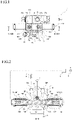
- Fig. 1 is a front view (schematic diagram) illustrating an example of a directional control valve 1 according to the present embodiment.
- Fig. 2 is a cross-sectional view taken along line II-II of Fig. 1 .
- Fig. 3 is an enlarged view of part III of Fig. 2 .
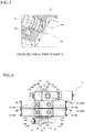
- Fig. 4 is a perspective view (schematic diagram) of a housing 10, and Fig. 5 is an enlarged cross-sectional view of part V of Fig. 4 (perspective view at the same angle as that of Fig. 4 ). It is noted that members having the same function are denoted by the same reference sign and not repeatedly described in all the drawings for describing the embodiment.
- the directional control valve 1 exercises control over work of a working cylinder that drives an external work device (e.g., work device used in a working vehicle), that is, changes over and stops a flow direction of a fluid used for the working cylinder 4 to work.
- an external work device e.g., work device used in a working vehicle
- the inventors of the present application considered adopting, as a directional control valve, a direct acting selector valve, i.e., a selector valve configured with a solenoid driving section that directly moves a spool.
- a direct acting selector valve i.e., a selector valve configured with a solenoid driving section that directly moves a spool.
- the direct acting selector valve is capable of stably moving the spool when the pressure and the flow rate of the fluid are relatively low (in a case where a maximum pressure of the fluid is approximately equal to or lower than 10 MPa and a maximum flow rate is so-called a low flow rate or a medium flow rate approximately equal to or lower than 50 liters/min).
- the direct acting selector valve may generate a greatly low driving force, compared with the conventional solenoid proportional pressure reducing valve since the solenoid driving section of the direct acting selector valve is configured to directly drive (move) the spool.
- the force driving the spool is lower, it is impossible to ignore an influence of the pressure of the fluid that is controlled by the spool and flows in a spool hole, specifically, the pressure of the fluid that is discharged from the working cylinder even if the pressure is quite low (e.g., as low as approximately 0.1 MPa) and that acts as a force moving the spool.
- an operation of the spool is not stable (specifically, a phenomenon that the spool does not move accurately in response to a control signal or the like occurs), causing unstable fluid control.
- the solenoid driving section may be made larger in size (e.g., to have a diameter approximately equal to or greater than 80 mm) to enhance a thrust of a needle. This makes it possible to ignore the influence that the pressure of the fluid discharged from the working cylinder acts as the force moving the spool. However, this method leads to increasing in size.
- the directional control valve 1 therefore, is capable of solving the complex problems described so far by being configured as follows.
- the directional control valve 1 is disposed between a main hydraulic pump 2 that is an external supply source (which is a hydraulic source in this case) of a fluid (which is a pressurized fluid in this case) at a predetermined pressure, and a working cylinder 4 that actuates a work device such as a fork or a bucket.
- the directional control valve 1 acts to control a flow passage and a flow rate of the fluid supplied to and discharged from the working cylinder 4. This enables settings of a working direction, an amount of work, a working speed of the work device.
- the directional control valve 1 is configured with a housing 10 and solenoid driving sections 30 provided on right and left side surfaces of the housing 10, respectively (hereinafter, a structurer including the housing 10 and the solenoid driving sections 30 are often referred to as "main body portion 100"). It is noted that in the present embodiment, the directional control valve 1 is also configured with an inlet 102 coupled to one surface (which will be described as "upper surface” on the basis of a layout of Fig. 1 for the sake of convenience of description) of the housing 10 while being stacked on the upper surface, and an outlet 104 coupled to the other surface (which will be described as "lower surface”) on the basis of the layout of Fig. 1 for the sake of convenience of description) of the housing 10 while being stacked on the lower surface.
- an inlet 102 coupled to one surface (which will be described as "upper surface” on the basis of a layout of Fig. 1 for the sake of convenience of description) of the housing 10 while being stacked on the upper surface
- outlet 104 coupled to the other surface (
- the inlet 102 is provided with an inlet port 16 that lets the fluid delivered from the external supply source (main hydraulic pump 2) to flow in.
- the main body portion 100 (housing 10 in this case) is provided with outlet ports 18A and 18B that let the fluid to flow out to the working cylinder 4.
- the outlet ports 18A and 18B also serve as ports that let the fluid discharged from the working cylinder 4 to flow in.
- the outlet 104 is provided with a tank port 19 that flows out the fluid discharged from the working cylinder 4 to a tank 3.
- the configurations of the directional control valve 1 are not limited to those described above, and the inlet port 16 and the tank port 19 may be directly provided in the housing 10 without providing the inlet and the outlet (not illustrated).
- the housing 10 is provided with a spool hole 20 that is a cylindrical space part in communication with the inlet port 16, the outlet ports 18A and 18B, and the tank port 19. Furthermore, a spool 22 that is provided movable in an axial direction and that changes and stops an amount of flow of the fluid is accommodated in the spool hole 20.
- the spool 22 and the spool hole 20 are each formed to have a circular cross-section, and the spool hole 20 is formed to penetrate from one side surface to the other side surface of the housing 10.
- the solenoid driving sections 30 are members acting to drive (move) the spool 22.
- two solenoid driving sections (specifically, the first solenoid driving section 30A and the second solenoid driving section 30B) are disposed symmetrically on the two side surfaces of the housing 10, respectively.
- a drive signal in response to an operation is transmitted to the corresponding solenoid driving section 30 via a control section 6, and the solenoid driving section 30 is driven to move a needle, thereby actuating (moving) the spool 22 (details of an operating principle will be described later).
- the housing 10 is provided with a supply flow passage 11 communicating with the inlet port 16, a first operation flow passage 12A and a second operation flow passage 12B communicating with the outlet ports 18A and 18B, respectively, and a first discharge flow passage 13A and a second discharge flow passage 13B communicating with the tank port 19.
- These flow passages are configured to communicate with the spool hole 20, and the supply flow passage 11 is, for example, disposed between the first operation flow passage 12A and the second operation flow passage 12B.
- the first operation flow passage 12A is disposed between the supply flow passage 11 and the first discharge flow passage 13A.
- the second operation flow passage 12B is disposed between the supply flow passage 11 and the second discharge flow passage 13B.
- the supply flow passage 11 is a flow passage that is connected to the main hydraulic pump 2 via the inlet port 16 and that supplies a fluid at a predetermined pressure (e.g., a high pressure of approximately 20 MPa) delivered from the main hydraulic pump 2.
- the first operation flow passage 12A and the second operation flow passage 12B are flow passages that are connected to the working cylinder 4 via the outlet ports 18A and 18B, respectively, and that supply a fluid at a predetermined pressure (e.g., a high pressure of approximately 20 MPa) to the working cylinder 4 and return a fluid at a predetermined pressure (e.g., a low pressure of approximately 2 MPa) discharged from the working cylinder 4.
- first discharge flow passage 13A and the second discharge flow passage 13B are flow passages that are connected to the tank 3 via the tank port 19 and that deliver a fluid at a predetermined pressure (e.g., a low pressure of approximately 0.1 MPa) discharged from the working cylinder 4 and flowing.
- a predetermined pressure e.g., a low pressure of approximately 0.1 MPa
- the fluid discharged by movement of a piston 4a of the working cylinder 4 is delivered to one of the first operation flow passage 12A and the second operation flow passage 12B in response to a moving direction of the piston 4a (for example, when the piston 4a moves upward in Fig. 2 , the fluid is discharged from the working cylinder 4 to the first operation flow passage 12A; and when the piston 4a moves downward in Fig. 2 , the fluid is discharged from the working cylinder 4 to the second operation flow passage 12B.)
- the fluid delivered to the first operation flow passage 12A flows only to the first discharge flow passage 13A (that is, not to the second discharge flow passage 13B).
- the fluid delivered to the second operation flow passage 12B flows only to the second discharge flow passage 13B (that is, not to the first discharge flow passage 13A).
- the spool 22 is formed to have the circular cross-section and accommodated in the spool hole 20 of the housing 10 to be movable in the axial direction (more specifically, slidable with a predetermined fitting tolerance).
- a notch that communicates the supply flow passage 11 with the first operation flow passage 12A and the second operation flow passage 12B, a notch that communicates the first operation flow passage 12A with the first discharge flow passage 13A, a notch that communicates the second operation flow passage 12B with the second discharge flow passage 13B, and the like are provided in an outer circumferential surface of the spool 22.
- seal member 14 e.g., an O-ring of rubber, elastomer, or the like
- O-ring of rubber elastomer, or the like
- the solenoid driving sections 30 (first solenoid driving section 30A and second solenoid driving section 30B) moving the spool 22 are provided in two ends of the spool 22, respectively. Since the two solenoid driving sections 30A and 30B are identical in basic configurations, one solenoid driving section 30A (part III of Fig. 2 ) will be described in detail by way of example. It is noted that in the present embodiment, an example of configurations of a so-called “pull-type proportional solenoid” will be described as the solenoid driving section 30. However, configurations of a "push-type” or a “push-pull type” can be adopted (not illustrated). Furthermore, for a case where it is unnecessary to regulate the flow rate and sufficient only to change over a direction, or the like, “on-off solenoid” configurations can be adopted as an alternative to the "proportional solenoid” (not illustrated).
- the solenoid driving section 30A includes, within a case 32, a coil 36 wound around a bobbin 34 while isolating a long conductor member, a fixed iron core 38 through which magnetic flux lines generated by excitation of the coil 36 pass, and a needle 22A (first needle) through which magnetic flux lines generated by excitation of the coil 36 pass, and which moves along an axial direction (that is, a direction along a central axis of the coil 36 wound around the bobbin 34, this same applies hereinafter) of the coil 36 by an attraction force generated due to the magnetic flux lines.
- the needle 22A is formed integrally with the spool 22 (into an integral structure worked from one member).
- the needle 22A is not limited to this example and may be configured to be formed separately and coupled to a first end portion 22a of the spool 22 (end portion closer to the solenoid driving section 30A) (not illustrated).
- the case 32 is a cylindrical member (that may be prismatic instead of being cylindrical) that accommodates the coil 36, the fixed iron core 38, the needle 22A, and the like, and is formed from, for example, a soft magnetic material such as carbon steel or free-cutting steel.
- This case 32 is fixed to a side surface of the housing 10 with bolts or the like (not illustrated).
- the coil 36 is configured such that a long insulating-coated conductor member is wound around the bobbin 34.
- the conductor member is, for example, a wire rod formed to have a cross-section of a circular shape, a square shape, or the like using a copper alloy or the like
- the conductor member may be a tape material, a sheet material, or the like (not illustrated).
- the fixed iron core 38 is a member that attracts the needle 22A through the magnetic flux lines generated by the excitation of the coil 36, and is formed from, for example, a soft magnetic material such as carbon steel or free-cutting steel.
- a base and a stator 38C that are disposed to be apart from each other in the axial direction of the coil 36 are provided as the fixed iron core 38.
- a first base 38A formed to have a collar portion provided in a first end portion 38a to extend radially and a second base 38B fitted into the first base 38A are provided, both having a cylindrical shape.
- the stator 38C is formed to have a collar portion provided in a first end portion 38c to extend radially with a cylindrical shape.
- the first base 38A has a tapered surface 38d having an outer peripheral surface a diameter of which is larger toward the first end portion 38a, in a second end portion 38b of the first base 38A.
- a transmission member (pin) 40 supported movably in the axial direction via a bush 44 and an urging member 42 urging the transmission member 40 toward the needle 22A are provided in the second base 38B.
- both the transmission member 40 and the bush 44 are formed from a non-magnetic material (such as a stainless alloy or a resin material).
- the urging member 42 is a so-called return spring configured with, for example, a coil spring and applies a force to move the needle 22A in an opposite direction to a direction in which the needle 22A is attracted by the fixed iron core 38 at the time of the excitation of the coil 36.
- the needle 22A is a member through which the magnetic flux lines generated when the coil 36 is excited pass and which moves along an axial direction of the coil 36 by the attraction force generated due to the magnetic flux lines and traveling to the fixed iron core 38.
- the needle 22A is formed from a soft magnetic material such as carbon steel or free-cutting steel.
- exciting the coil 36 of the solenoid driving section 30A generates the force for the fixed iron core 38 to attract the needle 22A and generates an action to move the needle 22A in a predetermined direction (which is a direction from the second end portion 38b to the first end portion 38a of the first base 38A in this case).
- demagnetizing the coil 36 dissipates the force for the fixed iron core 38 to attract the needle 22A and generates an action to move the needle 22A in a direction of returning the needle 22A to a neutral position by the urging force of the urging member 42.
- the urging force of the urging member 42 is transmitted to the needle 22A via the transmission member 40.
- the solenoid driving section 30A is the "proportional solenoid"
- a magnetic field at an intensity in response to an operation amount of the operation lever 5 i.e., the attraction force for the needle 22A
- the needle 22A is, therefore, moved to a position where the attraction force and the urging force of the urging member 42 are kept in balance and stopped at the position. That is, a moving amount of the spool 22 is set in response to an operator's operation, whereby the flow rate of the fluid by the directional control valve 1 is set and a working speed of the working cylinder 4 is controlled.
- the solenoid driving section 30B with a needle 22B is similar in configurations to the solenoid driving section 30A with the needle 22A (first needle) and is not repeatedly described. It is noted that the needle 22B is formed integrally with the spool 22 similarly to the needle 22A. However, as a modification, the needle 22B may be coupled to a second end portion 22b of the spool 22 (end portion closer to the solenoid driving section 30B) (not illustrated).
- the directional control valve 1 is a direct acting selector valve. Owing to this, because of a greatly low driving force that may be generated as compared with the conventional solenoid proportional pressure reducing valve, the directional control valve 1 possibly has problems that the operation of the spool 22 is not stable and that fluid control is unstable.
- the directional control valve 1 is provided with a pressure equalization circuit applying the same pressure (i.e., equally applying a pressure) to the first end portion 22a and the second end portion 22b of the spool 22.
- the pressure equalization circuit is configured as follows. Specifically, a connection flow passage 15 connecting the first discharge flow passage 13A to the second discharge flow passage 13B is provided in the outlet 104. In addition, a first pressure equalization flow passage 23A and a second pressure equalization flow passage 23B communicating with the connection flow passage 15 are provided continuously on both sides of the outlet 104 and the housing 10. Furthermore, a first pressure equalization chamber 24A (refer to Figs. 4 and the like) that is provided closer to the first end portion 22a of the spool 22 and that communicates with the first pressure equalization flow passage 23A is provided in the housing 10 (spool hole 20).
- This first pressure equalization chamber 24A acts to deliver the fluid in the connection flow passage 15 toward the first end portion 22a of the spool 22. Therefore, the pressure of the fluid in the connection flow passage 15 is applied to the first end portion 22a of the spool 22 (i.e., applied to the spool 22 in a direction from the first end portion 22a to the second end portion 22b).
- a second pressure equalization chamber 24B (configured symmetrically with the first pressure equalization chamber 24A illustrated in Figs. 4 and the like) that is provided closer to the second end portion 22b of the spool 22 and that communicates with the second pressure equalization flow passage 23B is provided.
- This second pressure equalization chamber 24B acts to deliver the fluid in the connection flow passage 15 toward the second end portion 22b of the spool 22. Therefore, the pressure of the fluid in the connection flow passage 15 is applied to the second end portion 22b of the spool 22 (i.e., applied to the spool 22 in a direction from the second end portion 22b to the first end portion 22a).
- the first pressure equalization flow passage 23A is provided as an independent flow passage that does not directly communicate with the first discharge flow passage 13A in the housing 10
- the second pressure equalization flow passage 23B is provided as an independent flow passage that does not directly communicate with the second discharge flow passage 13B in the housing 10.
- first pressure equalization flow passage 23A and the second pressure equalization flow passage 23B are substantially identical in structure (structured line-symmetric with respect to a central position in the axial direction of the spool hole 20 in the housing 10), and the first pressure equalization chamber 24A and the second pressure equalization chamber 24B are substantially identical in structured (structured line-symmetric with respect to the central position in the axial direction of the spool hole 20 in the housing 10).
- the present embodiment is not limited to the configurations.
- the fluid discharged from the working cylinder 4 under control of the spool 22 acts as a force to move the spool 22 (in the direction from the first end portion 22a to the second end portion 22b) when flowing through the first discharge flow passage 13A from the first operation flow passage 12A via within the spool hole 20.
- the fluid discharged from the working cylinder 4 under control of the spool 22 acts as a force to move the spool 22 (in the direction from the second end portion 22b to the first end portion 22a) when flowing through the second discharge flow passage 13B from the second operation flow passage 12B via within the spool hole 20.
- the pressure generated by the fluid in the connection flow passage 15 can be applied simultaneously to both the first end portion 22a and the second end portion 22b of the spool 22.
- the pressure here is equal to the pressure (e.g., low pressure of approximately 0.1 MPa) of the fluid flowing from the first discharge flow passage 13A and the second discharge flow passage 13B into the connection flow passage 15 (including an ignorable slight difference).
- the pressure equalization circuit may be configured such that the connection flow passage 15 is provided continuously in both the outlet 104 and the housing 10, or such that the connection flow passage 15, the first pressure equalization flow passage 23A, and the second pressure equalization flow passage 23B are provided in the housing 10 (not illustrated).
- each of the first pressure equalization chamber 24A and the second pressure equalization chamber 24B has a circumferential groove engraved on an inner circumferential surface of the spool hole 20 as a shape corresponding to a circumferential protrusion provided on an outer circumferential surface of a foundry core (not illustrated) used in a casting process of forming the spool hole 20.
- the housing 10 has a first stacking flow passage 27A that communicates with the first pressure equalization chamber 24A and a first stacking opening portion 26A formed open in an opposite surface to a surface in which an opening portion (first opening portion 25A) that is an end portion of the first pressure equalization flow passage 23A is provided, and a second stacking flow passage 27B that communicates with the second pressure equalization chamber 24B and a second stacking opening portion 26B formed open in the opposite surface to the surface in which an opening portion (second opening portion 25B) that is an end portion of the second pressure equalization flow passage 23B is provided.
- the first opening portion 25A and the first stacking opening portion 26A are provided at the same position and that the second opening portion 25B and the second stacking opening portion 26B are provided at the same position in a plan view.
- Fig. 6 illustrates configurations with two main body portions 100A and 100B as an example, the number of main body portions 100 is not limited to two but may be three or more depending on the number of installed working cylinders 4 (not illustrated).
- first opening portion 25A it is possible to simultaneously form the first opening portion 25A, the first pressure equalization flow passage 23A (constituent element in the housing 10), the first stacking flow passage 27A, and the first stacking opening portion 26A by one drilling.
- second opening portion 25B it is possible to simultaneously form the second opening portion 25B, the second pressure equalization flow passage 23B (constituent element in the housing 10), the second stacking flow passage 27B, and the second stacking opening portion 26B by one drilling. Therefore, it is possible to reduce the number of machining man-hours and shorten the takt time.
- the directional control valve according to the disclosure which is configured to cause the solenoid driving sections to directly drive the spool, is capable of setting the pressure and the flow rate of the fluid controlled by the spool high without relying on the scheme of increasing in size of the solenoid driving sections. Additionally, the directional control valve according to the disclosure is capable of avoiding the unstable operation of the spool and ensuring the stable fluid control at the time of driving the spool.
- a directional control valve (1) includes: a housing (10) having a cylindrical spool hole (20) communicating with an inlet port (16) letting a fluid from an external supply source (2) at a predetermined pressure and an outlet port (18A, 18B) flowing the fluid to a working cylinder (4); a spool (22) movable in the spool hole (20) axially and changing an amount of flow of the fluid; a first solenoid driving section (30A) having a first needle (22A) coupled to or integral with a first end portion (22a) of the spool (22) and driving the spool (22); and a second solenoid driving section (30B) having a second needle (22B) coupled to or integral with a second end portion (22b) of the spool (22) and driving the spool (22), the directional control valve (1) including a pressure equalization circuit equally applying a pressure to the end portions (22a, 22b).
Landscapes
- Engineering & Computer Science (AREA)
- General Engineering & Computer Science (AREA)
- Mechanical Engineering (AREA)
- Physics & Mathematics (AREA)
- Fluid Mechanics (AREA)
- Electromagnetism (AREA)
- Magnetically Actuated Valves (AREA)
- Multiple-Way Valves (AREA)
Abstract
Description
- The present invention relates to a directional control valve.
- A working vehicle such as a forklift or a construction machine is configured with a work device such as a fork or a bucket driven by a pressure fluid (hereinafter, often, simply referred to as "fluid"). To control driving of such a work device, a directional control valve that changes over or stops a flow direction of the fluid has been conventionally used.
- In a working vehicle configured with a work device that generates high output power, in particular, a pressure and a flow rate of the fluid controlled by the directional control valve are set relatively high. A pilot type selector valve with a solenoid proportional pressure reducing valve suited for controlling such a fluid has been developed.
- By way of example, a pilot type selector valve disclosed in PTL 1 (
JP-A-2004-232764 - The pilot type selector valve configured with the solenoid proportional pressure reducing valve disclosed in
PTL 1 as an example can set the pressure and the flow rate of the fluid controlled by the spool high and is, therefore, suited for an aim to achieve the high power output of the work device. On the other hand, however, the pilot type selector valve becomes larger in size and larger in weight, and has a more complicated structure because of the provision of the solenoid proportional pressure reducing valve. Furthermore, the need to always generate the pilot pressure (standby pressure) for driving the spool causes degradation in the fuel consumption (including power consumption) performance of a vehicle equipped with the directional control valve. Therefore, it is a challenge to realize a selector valve capable of setting the pressure and the flow rate of the fluid controlled by the spool high without relying of a scheme to increase the size of the selector valve. - It is conceivable, for example, that configuring the selector valve to simply omit the solenoid proportional pressure reducing valve and to cause a solenoid driving section to directly drive (move) the spool, a small-size, a weight reduction, and a simplified structure can be realized without increasing the size. On the other hand, however, the inventors of the present application discovered that with the direct driving configurations, the higher the pressure and the flow rate of the fluid to be controlled, the more the spool is difficult to actuate in response to a control command, resulting in unstable fluid control.
- The present invention has been accomplished under the circumstances, and an object of the present invention is to provide a directional control valve capable of setting high a pressure and a flow rate of a fluid to be controlled by a spool, avoiding an unstable operation of a spool, and ensuring stable fluid control in a configuration in which solenoid driving section directly drives the spool.
- According to an aspect, the problems described above are solved by the following disclosed solution.
- A directional control valve according to the disclosure includes: a housing having a cylindrical spool hole communicating with an inlet port that lets a fluid delivered from an external supply source at a predetermined pressure and an outlet port that lets the fluid to flow out to a working cylinder driving an external work device; a spool that is provided to be movable in the spool hole in an axial direction and that changes an amount of flow of the fluid; a first solenoid driving section having a first needle that is coupled to or integrally formed with a first end portion of the spool and that drives the spool; and a second solenoid driving section having a second needle that is coupled to or integrally formed with a second end portion of the spool and that drives the spool, the directional control valve including a pressure equalization circuit that equally applies a pressure to the first end portion and the second end portion of the spool.
- Furthermore, the housing has a first discharge flow passage and a second discharge flow passage to one of which the fluid discharged by movement of a piston of the working cylinder is caused to flow in response to a moving direction of the piston, and as the pressure equalization circuit, one of or each of the housing and an outlet coupled to the housing in a stacked state has a connection flow passage connecting the first discharge flow passage to the second discharge flow passage, and a first pressure equalization flow passage and a second pressure equalization flow passage communicating with the connection flow passage, and the spool hole has a first pressure equalization chamber provided closer to the first end portion of the spool and communicating with the first pressure equalization flow passage to apply a pressure of the fluid in the connection flow passage to the first end portion of the spool, and a second pressure equalization chamber provided closer to the second end portion of the spool and communicating with the second pressure equalization flow passage to apply the pressure of the fluid in the connection flow passage to the second end portion of the spool.
- Moreover, each of the first pressure equalization chamber and the second pressure equalization chamber has a circumferential groove engraved on an inner circumferential surface of the spool hole as a shape corresponding to a circumferential protrusion provided on an outer circumferential surface of a core used in a casting process of forming the spool hole.
- Furthermore, the housing has a first stacking flow passage that communicates with the first pressure equalization chamber and a first stacking opening portion formed open in an opposite surface to a surface in which an opening portion that is an end portion of the first pressure equalization flow passage is provided, and a second stacking flow passage that communicates with the second pressure equalization chamber and a second stacking opening portion formed open in the opposite surface to the surface in which an opening portion that is an end portion of the second pressure equalization flow passage is provided.
- Moreover, the fluid delivered from the external supply source is set to have a maximum pressure equal to or higher than 10 MPa and a maximum flow rate equal to or higher than 60 liters/min.
- According to the directional control valve according to the disclosure, in a configuration in which the solenoid driving section directly drives the spool, the pressure and the flow rate of the fluid controlled by the spool can be set high. Furthermore, the directional control valve according to the disclosure is capable of avoiding an unstable operation of the spool and ensuring stable fluid control at a time of driving the spool.
-
-
Fig. 1 is a front view illustrating an example of a directional control valve according to an embodiment of the present invention. -
Fig. 2 is a cross-sectional view taken along line II-II ofFig. 1 . -
Fig. 3 is an enlarged view of part III ofFig. 2 . -
Fig. 4 is a perspective view illustrating an example of a housing for the directional control valve illustrated inFig. 1 . -
Fig. 5 is an enlarged cross-sectional view of part V ofFig. 4 . -
Fig. 6 is a front view illustrating another example of the directional control valve according to the embodiment of the present invention. - An embodiment of the present invention will be described hereinafter in detail with reference to the drawings.
Fig. 1 is a front view (schematic diagram) illustrating an example of adirectional control valve 1 according to the present embodiment.Fig. 2 is a cross-sectional view taken along line II-II ofFig. 1 . InFig. 2 , however, peripheral devices and circuits are partially added for the sake of description. Furthermore,Fig. 3 is an enlarged view of part III ofFig. 2 . Moreover,Fig. 4 is a perspective view (schematic diagram) of ahousing 10, andFig. 5 is an enlarged cross-sectional view of part V ofFig. 4 (perspective view at the same angle as that ofFig. 4 ). It is noted that members having the same function are denoted by the same reference sign and not repeatedly described in all the drawings for describing the embodiment. - The
directional control valve 1 according to the present embodiment exercises control over work of a working cylinder that drives an external work device (e.g., work device used in a working vehicle), that is, changes over and stops a flow direction of a fluid used for the workingcylinder 4 to work. - First, for solving the aforementioned problems, the inventors of the present application considered adopting, as a directional control valve, a direct acting selector valve, i.e., a selector valve configured with a solenoid driving section that directly moves a spool. This is because such configurations enable omission of a pressure reducing valve and a proportional solenoid for controlling the pressure reducing valve, so that it is possible to realize a small-size, a weight reduction, and a simplified structure as well as an improvement in a fuel consumption performance by reducing a pilot pressure (standby pressure) for driving the spool.
- As a result of the consideration by trial manufacturing, experiments, and the like, the inventors of the present application found that the direct acting selector valve is capable of stably moving the spool when the pressure and the flow rate of the fluid are relatively low (in a case where a maximum pressure of the fluid is approximately equal to or lower than 10 MPa and a maximum flow rate is so-called a low flow rate or a medium flow rate approximately equal to or lower than 50 liters/min). However, it has become clear a problem that a spool moving operation becomes unstable in a case where the pressure and the flow rate of the fluid are relatively high (in a case where the maximum pressure of the fluid is approximately equal to or higher than 10 MPa and the maximum flow rate is a so-called high flow rate approximately equal to or higher than 60 liters/min).
- After further study, the inventors has found that the problems result from the fact that the direct acting selector valve may generate a greatly low driving force, compared with the conventional solenoid proportional pressure reducing valve since the solenoid driving section of the direct acting selector valve is configured to directly drive (move) the spool. In other words, as the force driving the spool is lower, it is impossible to ignore an influence of the pressure of the fluid that is controlled by the spool and flows in a spool hole, specifically, the pressure of the fluid that is discharged from the working cylinder even if the pressure is quite low (e.g., as low as approximately 0.1 MPa) and that acts as a force moving the spool. As a result, an operation of the spool is not stable (specifically, a phenomenon that the spool does not move accurately in response to a control signal or the like occurs), causing unstable fluid control.
- As a method of solving the problem, the solenoid driving section may be made larger in size (e.g., to have a diameter approximately equal to or greater than 80 mm) to enhance a thrust of a needle. This makes it possible to ignore the influence that the pressure of the fluid discharged from the working cylinder acts as the force moving the spool. However, this method leads to increasing in size.
- The
directional control valve 1 according to the present embodiment, therefore, is capable of solving the complex problems described so far by being configured as follows. - Overall configurations of the
directional control valve 1 according to the present embodiment will first be described. As illustrated inFigs. 1 and 2 , thedirectional control valve 1 is disposed between a mainhydraulic pump 2 that is an external supply source (which is a hydraulic source in this case) of a fluid (which is a pressurized fluid in this case) at a predetermined pressure, and a workingcylinder 4 that actuates a work device such as a fork or a bucket. Thedirectional control valve 1 acts to control a flow passage and a flow rate of the fluid supplied to and discharged from the workingcylinder 4. This enables settings of a working direction, an amount of work, a working speed of the work device. - The
directional control valve 1 is configured with ahousing 10 andsolenoid driving sections 30 provided on right and left side surfaces of thehousing 10, respectively (hereinafter, a structurer including thehousing 10 and thesolenoid driving sections 30 are often referred to as "main body portion 100"). It is noted that in the present embodiment, thedirectional control valve 1 is also configured with aninlet 102 coupled to one surface (which will be described as "upper surface" on the basis of a layout ofFig. 1 for the sake of convenience of description) of thehousing 10 while being stacked on the upper surface, and anoutlet 104 coupled to the other surface (which will be described as "lower surface") on the basis of the layout ofFig. 1 for the sake of convenience of description) of thehousing 10 while being stacked on the lower surface. By way of example, theinlet 102 is provided with aninlet port 16 that lets the fluid delivered from the external supply source (main hydraulic pump 2) to flow in. In addition, the main body portion 100 (housing 10 in this case) is provided withoutlet ports cylinder 4. It is noted that theoutlet ports cylinder 4 to flow in. Moreover, theoutlet 104 is provided with atank port 19 that flows out the fluid discharged from the workingcylinder 4 to a tank 3. However, the configurations of thedirectional control valve 1 are not limited to those described above, and theinlet port 16 and thetank port 19 may be directly provided in thehousing 10 without providing the inlet and the outlet (not illustrated). - The
housing 10 according to the present embodiment is provided with aspool hole 20 that is a cylindrical space part in communication with theinlet port 16, theoutlet ports tank port 19. Furthermore, aspool 22 that is provided movable in an axial direction and that changes and stops an amount of flow of the fluid is accommodated in thespool hole 20. By way of example, thespool 22 and thespool hole 20 are each formed to have a circular cross-section, and thespool hole 20 is formed to penetrate from one side surface to the other side surface of thehousing 10. - Furthermore, the
solenoid driving sections 30 are members acting to drive (move) thespool 22. In the present embodiment, two solenoid driving sections (specifically, the firstsolenoid driving section 30A and the secondsolenoid driving section 30B) are disposed symmetrically on the two side surfaces of thehousing 10, respectively. As an example of operation, when an operator operates anoperation lever 5, then a drive signal in response to an operation is transmitted to the correspondingsolenoid driving section 30 via a control section 6, and thesolenoid driving section 30 is driven to move a needle, thereby actuating (moving) the spool 22 (details of an operating principle will be described later). - Furthermore, the
housing 10 is provided with asupply flow passage 11 communicating with theinlet port 16, a firstoperation flow passage 12A and a secondoperation flow passage 12B communicating with theoutlet ports discharge flow passage 13A and a seconddischarge flow passage 13B communicating with thetank port 19. These flow passages are configured to communicate with thespool hole 20, and thesupply flow passage 11 is, for example, disposed between the firstoperation flow passage 12A and the secondoperation flow passage 12B. In addition, the firstoperation flow passage 12A is disposed between thesupply flow passage 11 and the firstdischarge flow passage 13A. Furthermore, the secondoperation flow passage 12B is disposed between thesupply flow passage 11 and the seconddischarge flow passage 13B. - Here, the
supply flow passage 11 is a flow passage that is connected to the mainhydraulic pump 2 via theinlet port 16 and that supplies a fluid at a predetermined pressure (e.g., a high pressure of approximately 20 MPa) delivered from the mainhydraulic pump 2. In addition, the firstoperation flow passage 12A and the secondoperation flow passage 12B are flow passages that are connected to the workingcylinder 4 via theoutlet ports cylinder 4 and return a fluid at a predetermined pressure (e.g., a low pressure of approximately 2 MPa) discharged from the workingcylinder 4. Furthermore, the firstdischarge flow passage 13A and the seconddischarge flow passage 13B are flow passages that are connected to the tank 3 via thetank port 19 and that deliver a fluid at a predetermined pressure (e.g., a low pressure of approximately 0.1 MPa) discharged from the workingcylinder 4 and flowing. - In the present embodiment, with circuit configurations controlled with the
spool hole 20 and thespool 22, the fluid discharged by movement of apiston 4a of the workingcylinder 4 is delivered to one of the firstoperation flow passage 12A and the secondoperation flow passage 12B in response to a moving direction of thepiston 4a (for example, when thepiston 4a moves upward inFig. 2 , the fluid is discharged from the workingcylinder 4 to the firstoperation flow passage 12A; and when thepiston 4a moves downward inFig. 2 , the fluid is discharged from the workingcylinder 4 to the secondoperation flow passage 12B.) Moreover, the fluid delivered to the firstoperation flow passage 12A flows only to the firstdischarge flow passage 13A (that is, not to the seconddischarge flow passage 13B). Conversely, the fluid delivered to the secondoperation flow passage 12B flows only to the seconddischarge flow passage 13B (that is, not to the firstdischarge flow passage 13A). - Next, the
spool 22 is formed to have the circular cross-section and accommodated in thespool hole 20 of thehousing 10 to be movable in the axial direction (more specifically, slidable with a predetermined fitting tolerance). - Although not illustrated, a notch that communicates the
supply flow passage 11 with the firstoperation flow passage 12A and the secondoperation flow passage 12B, a notch that communicates the firstoperation flow passage 12A with the firstdischarge flow passage 13A, a notch that communicates the secondoperation flow passage 12B with the seconddischarge flow passage 13B, and the like are provided in an outer circumferential surface of thespool 22. - It is noted that a seal member 14 (e.g., an O-ring of rubber, elastomer, or the like) is provided in each of necessary locations.
- Next, the solenoid driving sections 30 (first
solenoid driving section 30A and secondsolenoid driving section 30B) moving thespool 22 are provided in two ends of thespool 22, respectively. Since the twosolenoid driving sections solenoid driving section 30A (part III ofFig. 2 ) will be described in detail by way of example. It is noted that in the present embodiment, an example of configurations of a so-called "pull-type proportional solenoid" will be described as thesolenoid driving section 30. However, configurations of a "push-type" or a "push-pull type" can be adopted (not illustrated). Furthermore, for a case where it is unnecessary to regulate the flow rate and sufficient only to change over a direction, or the like, "on-off solenoid" configurations can be adopted as an alternative to the "proportional solenoid" (not illustrated). - As illustrated in
Figs. 2 and3 , thesolenoid driving section 30A according to the present embodiment includes, within acase 32, acoil 36 wound around abobbin 34 while isolating a long conductor member, a fixediron core 38 through which magnetic flux lines generated by excitation of thecoil 36 pass, and aneedle 22A (first needle) through which magnetic flux lines generated by excitation of thecoil 36 pass, and which moves along an axial direction (that is, a direction along a central axis of thecoil 36 wound around thebobbin 34, this same applies hereinafter) of thecoil 36 by an attraction force generated due to the magnetic flux lines. It is noted that theneedle 22A according to the present embodiment is formed integrally with the spool 22 (into an integral structure worked from one member). However, theneedle 22A is not limited to this example and may be configured to be formed separately and coupled to afirst end portion 22a of the spool 22 (end portion closer to thesolenoid driving section 30A) (not illustrated). - The
case 32 is a cylindrical member (that may be prismatic instead of being cylindrical) that accommodates thecoil 36, the fixediron core 38, theneedle 22A, and the like, and is formed from, for example, a soft magnetic material such as carbon steel or free-cutting steel. Thiscase 32 is fixed to a side surface of thehousing 10 with bolts or the like (not illustrated). - The
coil 36 is configured such that a long insulating-coated conductor member is wound around thebobbin 34. While the conductor member is, for example, a wire rod formed to have a cross-section of a circular shape, a square shape, or the like using a copper alloy or the like, the conductor member may be a tape material, a sheet material, or the like (not illustrated). - The fixed
iron core 38 is a member that attracts theneedle 22A through the magnetic flux lines generated by the excitation of thecoil 36, and is formed from, for example, a soft magnetic material such as carbon steel or free-cutting steel. In the present embodiment, a base and astator 38C that are disposed to be apart from each other in the axial direction of thecoil 36 are provided as the fixediron core 38. As the base here, afirst base 38A formed to have a collar portion provided in afirst end portion 38a to extend radially and asecond base 38B fitted into thefirst base 38A are provided, both having a cylindrical shape. On the other hand, thestator 38C is formed to have a collar portion provided in afirst end portion 38c to extend radially with a cylindrical shape. - Here, the
first base 38A according to the present embodiment has a taperedsurface 38d having an outer peripheral surface a diameter of which is larger toward thefirst end portion 38a, in asecond end portion 38b of thefirst base 38A. With the configurations, it is possible to enhance a magnetic flux density in thesecond end portion 38b and obtain an advantageous effect of making an attraction force constant irrespective of a position of theneedle 22A. - Moreover, a transmission member (pin) 40 supported movably in the axial direction via a
bush 44 and an urgingmember 42 urging thetransmission member 40 toward theneedle 22A are provided in thesecond base 38B. By way of example, both thetransmission member 40 and thebush 44 are formed from a non-magnetic material (such as a stainless alloy or a resin material). It is noted that the urgingmember 42 is a so-called return spring configured with, for example, a coil spring and applies a force to move theneedle 22A in an opposite direction to a direction in which theneedle 22A is attracted by the fixediron core 38 at the time of the excitation of thecoil 36. - The
needle 22A is a member through which the magnetic flux lines generated when thecoil 36 is excited pass and which moves along an axial direction of thecoil 36 by the attraction force generated due to the magnetic flux lines and traveling to the fixediron core 38. For example, theneedle 22A is formed from a soft magnetic material such as carbon steel or free-cutting steel. - With the aforementioned configurations, exciting the
coil 36 of thesolenoid driving section 30A according to the present embodiment generates the force for the fixediron core 38 to attract theneedle 22A and generates an action to move theneedle 22A in a predetermined direction (which is a direction from thesecond end portion 38b to thefirst end portion 38a of thefirst base 38A in this case). Moreover, demagnetizing thecoil 36 dissipates the force for the fixediron core 38 to attract theneedle 22A and generates an action to move theneedle 22A in a direction of returning theneedle 22A to a neutral position by the urging force of the urgingmember 42. In the present embodiment, the urging force of the urgingmember 42 is transmitted to theneedle 22A via thetransmission member 40. - Since the
solenoid driving section 30A according to the present embodiment is the "proportional solenoid," a magnetic field at an intensity in response to an operation amount of the operation lever 5 (i.e., the attraction force for theneedle 22A) is generated. Theneedle 22A is, therefore, moved to a position where the attraction force and the urging force of the urgingmember 42 are kept in balance and stopped at the position. That is, a moving amount of thespool 22 is set in response to an operator's operation, whereby the flow rate of the fluid by thedirectional control valve 1 is set and a working speed of the workingcylinder 4 is controlled. - On the other hand, the
solenoid driving section 30B with aneedle 22B (second needle) is similar in configurations to thesolenoid driving section 30A with theneedle 22A (first needle) and is not repeatedly described. It is noted that theneedle 22B is formed integrally with thespool 22 similarly to theneedle 22A. However, as a modification, theneedle 22B may be coupled to asecond end portion 22b of the spool 22 (end portion closer to thesolenoid driving section 30B) (not illustrated). - As described above, the
directional control valve 1 according to the present embodiment is a direct acting selector valve. Owing to this, because of a greatly low driving force that may be generated as compared with the conventional solenoid proportional pressure reducing valve, thedirectional control valve 1 possibly has problems that the operation of thespool 22 is not stable and that fluid control is unstable. - To address the problems, the
directional control valve 1 according to the present embodiment is provided with a pressure equalization circuit applying the same pressure (i.e., equally applying a pressure) to thefirst end portion 22a and thesecond end portion 22b of thespool 22. - In the present embodiment, the pressure equalization circuit is configured as follows. Specifically, a
connection flow passage 15 connecting the firstdischarge flow passage 13A to the seconddischarge flow passage 13B is provided in theoutlet 104. In addition, a first pressureequalization flow passage 23A and a second pressureequalization flow passage 23B communicating with theconnection flow passage 15 are provided continuously on both sides of theoutlet 104 and thehousing 10. Furthermore, a firstpressure equalization chamber 24A (refer toFigs. 4 and the like) that is provided closer to thefirst end portion 22a of thespool 22 and that communicates with the first pressureequalization flow passage 23A is provided in the housing 10 (spool hole 20). This firstpressure equalization chamber 24A acts to deliver the fluid in theconnection flow passage 15 toward thefirst end portion 22a of thespool 22. Therefore, the pressure of the fluid in theconnection flow passage 15 is applied to thefirst end portion 22a of the spool 22 (i.e., applied to thespool 22 in a direction from thefirst end portion 22a to thesecond end portion 22b). Likewise, a secondpressure equalization chamber 24B (configured symmetrically with the firstpressure equalization chamber 24A illustrated inFigs. 4 and the like) that is provided closer to thesecond end portion 22b of thespool 22 and that communicates with the second pressureequalization flow passage 23B is provided. This secondpressure equalization chamber 24B acts to deliver the fluid in theconnection flow passage 15 toward thesecond end portion 22b of thespool 22. Therefore, the pressure of the fluid in theconnection flow passage 15 is applied to thesecond end portion 22b of the spool 22 (i.e., applied to thespool 22 in a direction from thesecond end portion 22b to thefirst end portion 22a). By way of example, the first pressureequalization flow passage 23A is provided as an independent flow passage that does not directly communicate with the firstdischarge flow passage 13A in thehousing 10, and the second pressureequalization flow passage 23B is provided as an independent flow passage that does not directly communicate with the seconddischarge flow passage 13B in thehousing 10. Furthermore, the first pressureequalization flow passage 23A and the second pressureequalization flow passage 23B are substantially identical in structure (structured line-symmetric with respect to a central position in the axial direction of thespool hole 20 in the housing 10), and the firstpressure equalization chamber 24A and the secondpressure equalization chamber 24B are substantially identical in structured (structured line-symmetric with respect to the central position in the axial direction of thespool hole 20 in the housing 10). However, the present embodiment is not limited to the configurations. - With the configurations, it is possible to equally apply the pressure to the
first end portion 22a and thesecond end portion 22b of thespool 22. More specifically, the fluid discharged from the workingcylinder 4 under control of thespool 22 acts as a force to move the spool 22 (in the direction from thefirst end portion 22a to thesecond end portion 22b) when flowing through the firstdischarge flow passage 13A from the firstoperation flow passage 12A via within thespool hole 20. Likewise, the fluid discharged from the workingcylinder 4 under control of thespool 22 acts as a force to move the spool 22 (in the direction from thesecond end portion 22b to thefirst end portion 22a) when flowing through the seconddischarge flow passage 13B from the secondoperation flow passage 12B via within thespool hole 20. In either case, the pressure generated by the fluid in theconnection flow passage 15 can be applied simultaneously to both thefirst end portion 22a and thesecond end portion 22b of thespool 22. The pressure here is equal to the pressure (e.g., low pressure of approximately 0.1 MPa) of the fluid flowing from the firstdischarge flow passage 13A and the seconddischarge flow passage 13B into the connection flow passage 15 (including an ignorable slight difference). - It is thereby possible to eliminate an influence of the fluid that acts as the force to move the
spool 22 at the time of flowing in thespool hole 20 or reduce the influence to an ignorable degree, so that it is possible to avoid the unstable operation of thespool 22 and stabilize the fluid control. - As a result, even when the pressure and the flow rate of the fluid are set high (on the assumption herein that a maximum pressure of the fluid is equal to or higher than 10 MPa and a maximum flow rate is approximately 60 to 160 liters/min), it is possible to realize configurations of directly and stably moving the
spool 22 without relying on the solution to increasing in size of thesolenoid driving sections 30. - As modifications of the pressure equalization circuit, the pressure equalization circuit may be configured such that the
connection flow passage 15 is provided continuously in both theoutlet 104 and thehousing 10, or such that theconnection flow passage 15, the first pressureequalization flow passage 23A, and the second pressureequalization flow passage 23B are provided in the housing 10 (not illustrated). - Moreover, as characteristic configurations of the
directional control valve 1 according to the present embodiment, each of the firstpressure equalization chamber 24A and the secondpressure equalization chamber 24B has a circumferential groove engraved on an inner circumferential surface of thespool hole 20 as a shape corresponding to a circumferential protrusion provided on an outer circumferential surface of a foundry core (not illustrated) used in a casting process of forming thespool hole 20. - With the configurations, at a time of forming the
spool hole 20 by casting, it is possible to form the firstpressure equalization chamber 24A and the secondpressure equalization chamber 24B simultaneously. In other words, it is possible to reduce the number of machining man-hours and shorten takt time because of no need to form thespool hole 20 by separate machining (cutting). - Furthermore, the
housing 10 has a first stackingflow passage 27A that communicates with the firstpressure equalization chamber 24A and a first stackingopening portion 26A formed open in an opposite surface to a surface in which an opening portion (first opening portion 25A) that is an end portion of the first pressureequalization flow passage 23A is provided, and a second stackingflow passage 27B that communicates with the secondpressure equalization chamber 24B and a second stacking openingportion 26B formed open in the opposite surface to the surface in which an opening portion (second opening portion 25B) that is an end portion of the second pressureequalization flow passage 23B is provided. At this time, it is more preferable that thefirst opening portion 25A and the first stackingopening portion 26A are provided at the same position and that thesecond opening portion 25B and the second stacking openingportion 26B are provided at the same position in a plan view. - With the configurations, as in another embodiment illustrated in
Fig. 6 , configurations of stacking a plurality ofmain body portions 100 between theinlet 102 and theoutlet 104 can be realized. Therefore, it is possible to easily construct thedirectional control valve 1 with the number of stackedmain body portions 100 increased or decreased depending on the number of installed workingcylinders 4 to be controlled. WhileFig. 6 illustrates configurations with twomain body portions main body portions 100 is not limited to two but may be three or more depending on the number of installed working cylinders 4 (not illustrated). - Moreover, it is possible to simultaneously form the
first opening portion 25A, the first pressureequalization flow passage 23A (constituent element in the housing 10), the first stackingflow passage 27A, and the first stackingopening portion 26A by one drilling. Likewise, it is possible to simultaneously form thesecond opening portion 25B, the second pressureequalization flow passage 23B (constituent element in the housing 10), the second stackingflow passage 27B, and the second stacking openingportion 26B by one drilling. Therefore, it is possible to reduce the number of machining man-hours and shorten the takt time. - As described so far, the directional control valve according to the disclosure, which is configured to cause the solenoid driving sections to directly drive the spool, is capable of setting the pressure and the flow rate of the fluid controlled by the spool high without relying on the scheme of increasing in size of the solenoid driving sections. Additionally, the directional control valve according to the disclosure is capable of avoiding the unstable operation of the spool and ensuring the stable fluid control at the time of driving the spool.
- Furthermore, realizing configurations without the solenoid proportional pressure reducing valve not only enables small-sized, the weight reduction, and simple configurations but also eliminates the standby pressure for control, thus making it possible to improve a fuel consumption (power consumption) performance of a vehicle equipped with the directional control valve.
- Needless to say, the present invention is not limited to the embodiments described so far and can be changed and modified in various manners without departing from the present invention.
- A directional control valve (1) includes: a housing (10) having a cylindrical spool hole (20) communicating with an inlet port (16) letting a fluid from an external supply source (2) at a predetermined pressure and an outlet port (18A, 18B) flowing the fluid to a working cylinder (4); a spool (22) movable in the spool hole (20) axially and changing an amount of flow of the fluid; a first solenoid driving section (30A) having a first needle (22A) coupled to or integral with a first end portion (22a) of the spool (22) and driving the spool (22); and a second solenoid driving section (30B) having a second needle (22B) coupled to or integral with a second end portion (22b) of the spool (22) and driving the spool (22), the directional control valve (1) including a pressure equalization circuit equally applying a pressure to the end portions (22a, 22b).
Claims (5)
- A directional control valve (1) comprising:a housing (10) having a cylindrical spool hole (20) communicating with an inlet port (16) that lets a fluid delivered from an external supply source (2) at a predetermined pressure and an outlet port (18A, 18B) that lets the fluid to flow out to a working cylinder (4) driving an external work device;a spool (22) that is provided to be movable in the spool hole (20) in an axial direction and that changes an amount of flow of the fluid;a first solenoid driving section (30A) having a first needle (22A) that is coupled to or integrally formed with a first end portion (22a) of the spool (22) and that drives the spool (22); anda second solenoid driving section (30B) having a second needle (22B) that is coupled to or integrally formed with a second end portion (22b) of the spool (22) and that drives the spool (22), whereinthe directional control valve (1) comprises a pressure equalization circuit that equally applies a pressure to the first end portion (22a) and the second end portion (22b) of the spool (22).
- The directional control valve (1) according to claim 1, whereinthe housing (10) has a first discharge flow passage (13A) and a second discharge flow passage (13B) to one of which the fluid discharged by movement of a piston (4a) of the working cylinder (4) is caused to flow in response to a moving direction of the piston, andas the pressure equalization circuit, one of or each of the housing (10) and an outlet (104) coupled to the housing (10) in a stacked state has a connection flow passage (15) connecting the first discharge flow passage (13A) to the second discharge flow passage (13B), and a first pressure equalization flow passage (23A) and a second pressure equalization flow passage (23B) communicating with the connection flow passage (15), and the spool hole (20) has a first pressure equalization chamber (24A) provided closer to the first end portion (22a) of the spool (22) and communicating with the first pressure equalization flow passage (23A) to apply a pressure of the fluid in the connection flow passage (15) to the first end portion (22a) of the spool (22), and a second pressure equalization chamber (24B) provided closer to the second end portion (22b) of the spool (22) and communicating with the second pressure equalization flow passage (23B) to apply the pressure of the fluid in the connection flow passage (15) to the second end portion (22b) of the spool (22).
- The directional control valve (1) according to claim 2, wherein
each of the first pressure equalization chamber (24A) and the second pressure equalization chamber (24B) has a circumferential groove engraved on an inner circumferential surface of the spool hole (20) as a shape corresponding to a circumferential protrusion provided on an outer circumferential surface of a core used in a casting process of forming the spool hole (20). - The directional control valve (1) according to claim 2 or 3, wherein
the housing (10) has a first stacking flow passage (27A) that communicates with the first pressure equalization chamber (24A) and a first stacking opening portion (26A) formed open in an opposite surface to a surface in which an opening portion (25A) that is an end portion of the first pressure equalization flow passage (23A) is provided, and a second stacking flow passage (27B) that communicates with the second pressure equalization chamber (24B) and a second stacking opening portion (26B) formed open in the opposite surface to the surface in which an opening portion (25B) that is an end portion of the second pressure equalization flow passage (23B) is provided. - The directional control valve (1) according to any one of claims 1 to 4, wherein
the fluid delivered from the external supply source (2) is set to have a maximum pressure equal to or higher than 10 MPa and a maximum flow rate equal to or higher than 60 liters/min.
Applications Claiming Priority (1)
| Application Number | Priority Date | Filing Date | Title |
|---|---|---|---|
| JP2021111282A JP7543220B2 (en) | 2021-07-05 | 2021-07-05 | Directional valve |
Publications (2)
| Publication Number | Publication Date |
|---|---|
| EP4116592A1 true EP4116592A1 (en) | 2023-01-11 |
| EP4116592B1 EP4116592B1 (en) | 2024-10-16 |
Family
ID=82163522
Family Applications (1)
| Application Number | Title | Priority Date | Filing Date |
|---|---|---|---|
| EP22180050.1A Active EP4116592B1 (en) | 2021-07-05 | 2022-06-21 | Directional control valve |
Country Status (6)
| Country | Link |
|---|---|
| US (1) | US11841091B2 (en) |
| EP (1) | EP4116592B1 (en) |
| JP (1) | JP7543220B2 (en) |
| CN (1) | CN115585287A (en) |
| AU (1) | AU2022204301B2 (en) |
| CA (1) | CA3164603C (en) |
Citations (6)
| Publication number | Priority date | Publication date | Assignee | Title |
|---|---|---|---|---|
| DE3540553A1 (en) * | 1985-11-15 | 1987-05-27 | Reinhard Ing Grad Kucharzyk | Silent directional control valve |
| JPS63208911A (en) * | 1987-02-26 | 1988-08-30 | Atsugi Motor Parts Co Ltd | pressure control valve |
| US5284220A (en) * | 1988-07-25 | 1994-02-08 | Atsugi Unisia Corporation | Pressure control valve assembly for hydraulic circuit and automotive rear wheel steering system utilizing the same |
| US5640987A (en) * | 1994-04-05 | 1997-06-24 | Sturman; Oded E. | Digital two, three, and four way solenoid control valves |
| FR2784733A1 (en) * | 1998-10-20 | 2000-04-21 | Mannesmann Rexroth Sa | Hydraulic fluid distributor, comprises an electric action with damped slider operation |
| JP2004232764A (en) | 2003-01-31 | 2004-08-19 | Kayaba Ind Co Ltd | Pilot operated switching valve |
Family Cites Families (5)
| Publication number | Priority date | Publication date | Assignee | Title |
|---|---|---|---|---|
| US4406307A (en) * | 1981-03-31 | 1983-09-27 | Double A Products Company | Directional valve with spool transfer loop |
| JPH102284A (en) * | 1996-06-17 | 1998-01-06 | Toyota Autom Loom Works Ltd | Variable displacement compressor and its control method |
| KR100928035B1 (en) * | 2006-09-25 | 2009-11-24 | 동아특수정밀 주식회사 | Instantaneous energized air valve with magnetic coil |
| JP6491523B2 (en) * | 2015-04-15 | 2019-03-27 | Kyb株式会社 | Fluid pressure control device |
| JP6423754B2 (en) * | 2015-04-24 | 2018-11-14 | Kyb株式会社 | Flow control valve |
-
2021
- 2021-07-05 JP JP2021111282A patent/JP7543220B2/en active Active
-
2022
- 2022-06-20 AU AU2022204301A patent/AU2022204301B2/en active Active
- 2022-06-21 EP EP22180050.1A patent/EP4116592B1/en active Active
- 2022-06-21 CA CA3164603A patent/CA3164603C/en active Active
- 2022-06-28 US US17/851,495 patent/US11841091B2/en active Active
- 2022-07-04 CN CN202210786528.0A patent/CN115585287A/en active Pending
Patent Citations (6)
| Publication number | Priority date | Publication date | Assignee | Title |
|---|---|---|---|---|
| DE3540553A1 (en) * | 1985-11-15 | 1987-05-27 | Reinhard Ing Grad Kucharzyk | Silent directional control valve |
| JPS63208911A (en) * | 1987-02-26 | 1988-08-30 | Atsugi Motor Parts Co Ltd | pressure control valve |
| US5284220A (en) * | 1988-07-25 | 1994-02-08 | Atsugi Unisia Corporation | Pressure control valve assembly for hydraulic circuit and automotive rear wheel steering system utilizing the same |
| US5640987A (en) * | 1994-04-05 | 1997-06-24 | Sturman; Oded E. | Digital two, three, and four way solenoid control valves |
| FR2784733A1 (en) * | 1998-10-20 | 2000-04-21 | Mannesmann Rexroth Sa | Hydraulic fluid distributor, comprises an electric action with damped slider operation |
| JP2004232764A (en) | 2003-01-31 | 2004-08-19 | Kayaba Ind Co Ltd | Pilot operated switching valve |
Also Published As
| Publication number | Publication date |
|---|---|
| AU2022204301A1 (en) | 2023-01-19 |
| CN115585287A (en) | 2023-01-10 |
| JP7543220B2 (en) | 2024-09-02 |
| JP2023008042A (en) | 2023-01-19 |
| AU2022204301B2 (en) | 2024-03-14 |
| CA3164603C (en) | 2025-10-07 |
| US11841091B2 (en) | 2023-12-12 |
| US20230003313A1 (en) | 2023-01-05 |
| EP4116592B1 (en) | 2024-10-16 |
| CA3164603A1 (en) | 2023-01-05 |
Similar Documents
| Publication | Publication Date | Title |
|---|---|---|
| US8397759B2 (en) | Electromagnetic spool valve | |
| US5640987A (en) | Digital two, three, and four way solenoid control valves | |
| JP3519370B2 (en) | Solenoid operated double spool control valve | |
| US11293560B2 (en) | Solenoid flow control valve | |
| US11274752B2 (en) | Flow control valve with load-sense signal generation | |
| JP2012241740A (en) | Solenoid valve and hydraulic control device | |
| KR100476246B1 (en) | Proportional pressure control valve | |
| EP3680530B1 (en) | Cap with electromagnetic proportional valve | |
| EP4116592B1 (en) | Directional control valve | |
| EP1434957B1 (en) | Auto-relieving pressure modulating valve | |
| JP7543219B2 (en) | Directional valve | |
| JP2009058013A (en) | Solenoid valve | |
| KR20210030880A (en) | Fluid control equipment, construction machinery and control method of fluid control equipment | |
| JP7733685B2 (en) | Solenoid proportional relief valve | |
| JP5470180B2 (en) | Control valve | |
| JP2003028335A (en) | Linear solenoid valve | |
| JP2020101237A (en) | Control valve | |
| JP7186584B2 (en) | Solenoid valves, directional control valves and construction machinery | |
| JPH049487Y2 (en) | ||
| JP2020101236A (en) | Solenoid valve | |
| JPH01307574A (en) | Oil pressure control valve | |
| JP2000120913A (en) | Proportional electromagnetic directional flow control valve with pressure compensating valve | |
| JPH0914472A (en) | Spool type servo valve |
Legal Events
| Date | Code | Title | Description |
|---|---|---|---|
| PUAI | Public reference made under article 153(3) epc to a published international application that has entered the european phase |
Free format text: ORIGINAL CODE: 0009012 |
|
| STAA | Information on the status of an ep patent application or granted ep patent |
Free format text: STATUS: REQUEST FOR EXAMINATION WAS MADE |
|
| 17P | Request for examination filed |
Effective date: 20220621 |
|
| AK | Designated contracting states |
Kind code of ref document: A1 Designated state(s): AL AT BE BG CH CY CZ DE DK EE ES FI FR GB GR HR HU IE IS IT LI LT LU LV MC MK MT NL NO PL PT RO RS SE SI SK SM TR |
|
| GRAP | Despatch of communication of intention to grant a patent |
Free format text: ORIGINAL CODE: EPIDOSNIGR1 |
|
| STAA | Information on the status of an ep patent application or granted ep patent |
Free format text: STATUS: GRANT OF PATENT IS INTENDED |
|
| INTG | Intention to grant announced |
Effective date: 20240514 |
|
| P01 | Opt-out of the competence of the unified patent court (upc) registered |
Free format text: CASE NUMBER: APP_43288/2024 Effective date: 20240724 |
|
| GRAS | Grant fee paid |
Free format text: ORIGINAL CODE: EPIDOSNIGR3 |
|
| GRAA | (expected) grant |
Free format text: ORIGINAL CODE: 0009210 |
|
| STAA | Information on the status of an ep patent application or granted ep patent |
Free format text: STATUS: THE PATENT HAS BEEN GRANTED |
|
| RAP3 | Party data changed (applicant data changed or rights of an application transferred) |
Owner name: KABUSHIKI KAISHA TOYOTA JIDOSHOKKI Owner name: NISHINA INDUSTRIAL CO., LTD. |
|
| AK | Designated contracting states |
Kind code of ref document: B1 Designated state(s): AL AT BE BG CH CY CZ DE DK EE ES FI FR GB GR HR HU IE IS IT LI LT LU LV MC MK MT NL NO PL PT RO RS SE SI SK SM TR |
|
| REG | Reference to a national code |
Ref country code: GB Ref legal event code: FG4D |
|
| REG | Reference to a national code |
Ref country code: NL Ref legal event code: FP |
|
| REG | Reference to a national code |
Ref country code: DE Ref legal event code: R096 Ref document number: 602022006803 Country of ref document: DE Ref country code: CH Ref legal event code: EP |
|
| REG | Reference to a national code |
Ref country code: IE Ref legal event code: FG4D |
|
| REG | Reference to a national code |
Ref country code: LT Ref legal event code: MG9D |
|
| REG | Reference to a national code |
Ref country code: SE Ref legal event code: TRGR |
|
| REG | Reference to a national code |
Ref country code: AT Ref legal event code: MK05 Ref document number: 1733114 Country of ref document: AT Kind code of ref document: T Effective date: 20241016 |
|
| PG25 | Lapsed in a contracting state [announced via postgrant information from national office to epo] |
Ref country code: HR Free format text: LAPSE BECAUSE OF FAILURE TO SUBMIT A TRANSLATION OF THE DESCRIPTION OR TO PAY THE FEE WITHIN THE PRESCRIBED TIME-LIMIT Effective date: 20241016 Ref country code: IS Free format text: LAPSE BECAUSE OF FAILURE TO SUBMIT A TRANSLATION OF THE DESCRIPTION OR TO PAY THE FEE WITHIN THE PRESCRIBED TIME-LIMIT Effective date: 20250216 Ref country code: PT Free format text: LAPSE BECAUSE OF FAILURE TO SUBMIT A TRANSLATION OF THE DESCRIPTION OR TO PAY THE FEE WITHIN THE PRESCRIBED TIME-LIMIT Effective date: 20250217 |
|
| PG25 | Lapsed in a contracting state [announced via postgrant information from national office to epo] |
Ref country code: FI Free format text: LAPSE BECAUSE OF FAILURE TO SUBMIT A TRANSLATION OF THE DESCRIPTION OR TO PAY THE FEE WITHIN THE PRESCRIBED TIME-LIMIT Effective date: 20241016 |
|
| PG25 | Lapsed in a contracting state [announced via postgrant information from national office to epo] |
Ref country code: BG Free format text: LAPSE BECAUSE OF FAILURE TO SUBMIT A TRANSLATION OF THE DESCRIPTION OR TO PAY THE FEE WITHIN THE PRESCRIBED TIME-LIMIT Effective date: 20241016 |
|
| PG25 | Lapsed in a contracting state [announced via postgrant information from national office to epo] |
Ref country code: ES Free format text: LAPSE BECAUSE OF FAILURE TO SUBMIT A TRANSLATION OF THE DESCRIPTION OR TO PAY THE FEE WITHIN THE PRESCRIBED TIME-LIMIT Effective date: 20241016 |
|
| PG25 | Lapsed in a contracting state [announced via postgrant information from national office to epo] |
Ref country code: NO Free format text: LAPSE BECAUSE OF FAILURE TO SUBMIT A TRANSLATION OF THE DESCRIPTION OR TO PAY THE FEE WITHIN THE PRESCRIBED TIME-LIMIT Effective date: 20250116 |
|
| PG25 | Lapsed in a contracting state [announced via postgrant information from national office to epo] |
Ref country code: GR Free format text: LAPSE BECAUSE OF FAILURE TO SUBMIT A TRANSLATION OF THE DESCRIPTION OR TO PAY THE FEE WITHIN THE PRESCRIBED TIME-LIMIT Effective date: 20250117 Ref country code: LV Free format text: LAPSE BECAUSE OF FAILURE TO SUBMIT A TRANSLATION OF THE DESCRIPTION OR TO PAY THE FEE WITHIN THE PRESCRIBED TIME-LIMIT Effective date: 20241016 Ref country code: AT Free format text: LAPSE BECAUSE OF FAILURE TO SUBMIT A TRANSLATION OF THE DESCRIPTION OR TO PAY THE FEE WITHIN THE PRESCRIBED TIME-LIMIT Effective date: 20241016 |
|
| PG25 | Lapsed in a contracting state [announced via postgrant information from national office to epo] |
Ref country code: PL Free format text: LAPSE BECAUSE OF FAILURE TO SUBMIT A TRANSLATION OF THE DESCRIPTION OR TO PAY THE FEE WITHIN THE PRESCRIBED TIME-LIMIT Effective date: 20241016 |
|
| PG25 | Lapsed in a contracting state [announced via postgrant information from national office to epo] |
Ref country code: RS Free format text: LAPSE BECAUSE OF FAILURE TO SUBMIT A TRANSLATION OF THE DESCRIPTION OR TO PAY THE FEE WITHIN THE PRESCRIBED TIME-LIMIT Effective date: 20250116 |
|
| PG25 | Lapsed in a contracting state [announced via postgrant information from national office to epo] |
Ref country code: SM Free format text: LAPSE BECAUSE OF FAILURE TO SUBMIT A TRANSLATION OF THE DESCRIPTION OR TO PAY THE FEE WITHIN THE PRESCRIBED TIME-LIMIT Effective date: 20241016 |
|
| PGFP | Annual fee paid to national office [announced via postgrant information from national office to epo] |
Ref country code: DE Payment date: 20250626 Year of fee payment: 4 |
|
| PG25 | Lapsed in a contracting state [announced via postgrant information from national office to epo] |
Ref country code: DK Free format text: LAPSE BECAUSE OF FAILURE TO SUBMIT A TRANSLATION OF THE DESCRIPTION OR TO PAY THE FEE WITHIN THE PRESCRIBED TIME-LIMIT Effective date: 20241016 |
|
| PGFP | Annual fee paid to national office [announced via postgrant information from national office to epo] |
Ref country code: NL Payment date: 20250618 Year of fee payment: 4 Ref country code: BE Payment date: 20250617 Year of fee payment: 4 |
|
| REG | Reference to a national code |
Ref country code: DE Ref legal event code: R097 Ref document number: 602022006803 Country of ref document: DE |
|
| PG25 | Lapsed in a contracting state [announced via postgrant information from national office to epo] |
Ref country code: EE Free format text: LAPSE BECAUSE OF FAILURE TO SUBMIT A TRANSLATION OF THE DESCRIPTION OR TO PAY THE FEE WITHIN THE PRESCRIBED TIME-LIMIT Effective date: 20241016 |
|
| PGFP | Annual fee paid to national office [announced via postgrant information from national office to epo] |
Ref country code: FR Payment date: 20250626 Year of fee payment: 4 |
|
| PG25 | Lapsed in a contracting state [announced via postgrant information from national office to epo] |
Ref country code: RO Free format text: LAPSE BECAUSE OF FAILURE TO SUBMIT A TRANSLATION OF THE DESCRIPTION OR TO PAY THE FEE WITHIN THE PRESCRIBED TIME-LIMIT Effective date: 20241016 |
|
| PG25 | Lapsed in a contracting state [announced via postgrant information from national office to epo] |
Ref country code: SK Free format text: LAPSE BECAUSE OF FAILURE TO SUBMIT A TRANSLATION OF THE DESCRIPTION OR TO PAY THE FEE WITHIN THE PRESCRIBED TIME-LIMIT Effective date: 20241016 |
|
| PG25 | Lapsed in a contracting state [announced via postgrant information from national office to epo] |
Ref country code: CZ Free format text: LAPSE BECAUSE OF FAILURE TO SUBMIT A TRANSLATION OF THE DESCRIPTION OR TO PAY THE FEE WITHIN THE PRESCRIBED TIME-LIMIT Effective date: 20241016 |
|
| PGFP | Annual fee paid to national office [announced via postgrant information from national office to epo] |
Ref country code: SE Payment date: 20250618 Year of fee payment: 4 |
|
| PLBE | No opposition filed within time limit |
Free format text: ORIGINAL CODE: 0009261 |
|
| STAA | Information on the status of an ep patent application or granted ep patent |
Free format text: STATUS: NO OPPOSITION FILED WITHIN TIME LIMIT |
|
| PG25 | Lapsed in a contracting state [announced via postgrant information from national office to epo] |
Ref country code: SE Free format text: LAPSE BECAUSE OF FAILURE TO SUBMIT A TRANSLATION OF THE DESCRIPTION OR TO PAY THE FEE WITHIN THE PRESCRIBED TIME-LIMIT Effective date: 20241016 |
|
| 26N | No opposition filed |
Effective date: 20250717 |
|
| PGFP | Annual fee paid to national office [announced via postgrant information from national office to epo] |
Ref country code: IT Payment date: 20250630 Year of fee payment: 4 |
|
| REG | Reference to a national code |
Ref country code: CH Ref legal event code: H13 Free format text: ST27 STATUS EVENT CODE: U-0-0-H10-H13 (AS PROVIDED BY THE NATIONAL OFFICE) Effective date: 20260127 |
|
| PG25 | Lapsed in a contracting state [announced via postgrant information from national office to epo] |
Ref country code: MC Free format text: LAPSE BECAUSE OF FAILURE TO SUBMIT A TRANSLATION OF THE DESCRIPTION OR TO PAY THE FEE WITHIN THE PRESCRIBED TIME-LIMIT Effective date: 20241016 |
|
| PG25 | Lapsed in a contracting state [announced via postgrant information from national office to epo] |
Ref country code: LU Free format text: LAPSE BECAUSE OF NON-PAYMENT OF DUE FEES Effective date: 20250621 |
|
| PG25 | Lapsed in a contracting state [announced via postgrant information from national office to epo] |
Ref country code: IE Free format text: LAPSE BECAUSE OF NON-PAYMENT OF DUE FEES Effective date: 20250621 |
|
| PG25 | Lapsed in a contracting state [announced via postgrant information from national office to epo] |
Ref country code: CH Free format text: LAPSE BECAUSE OF NON-PAYMENT OF DUE FEES Effective date: 20250630 |