EP4116119B1 - Vehicle thermal management system and vehicle - Google Patents
Vehicle thermal management system and vehicle Download PDFInfo
- Publication number
- EP4116119B1 EP4116119B1 EP22761345.2A EP22761345A EP4116119B1 EP 4116119 B1 EP4116119 B1 EP 4116119B1 EP 22761345 A EP22761345 A EP 22761345A EP 4116119 B1 EP4116119 B1 EP 4116119B1
- Authority
- EP
- European Patent Office
- Prior art keywords
- coolant
- flow path
- water pump
- coolant loop
- way valve
- Prior art date
- Legal status (The legal status is an assumption and is not a legal conclusion. Google has not performed a legal analysis and makes no representation as to the accuracy of the status listed.)
- Active
Links
Images


Classifications
-
- B—PERFORMING OPERATIONS; TRANSPORTING
- B60—VEHICLES IN GENERAL
- B60K—ARRANGEMENT OR MOUNTING OF PROPULSION UNITS OR OF TRANSMISSIONS IN VEHICLES; ARRANGEMENT OR MOUNTING OF PLURAL DIVERSE PRIME-MOVERS IN VEHICLES; AUXILIARY DRIVES FOR VEHICLES; INSTRUMENTATION OR DASHBOARDS FOR VEHICLES; ARRANGEMENTS IN CONNECTION WITH COOLING, AIR INTAKE, GAS EXHAUST OR FUEL SUPPLY OF PROPULSION UNITS IN VEHICLES
- B60K11/00—Arrangement in connection with cooling of propulsion units
- B60K11/02—Arrangement in connection with cooling of propulsion units with liquid cooling
-
- B—PERFORMING OPERATIONS; TRANSPORTING
- B60—VEHICLES IN GENERAL
- B60K—ARRANGEMENT OR MOUNTING OF PROPULSION UNITS OR OF TRANSMISSIONS IN VEHICLES; ARRANGEMENT OR MOUNTING OF PLURAL DIVERSE PRIME-MOVERS IN VEHICLES; AUXILIARY DRIVES FOR VEHICLES; INSTRUMENTATION OR DASHBOARDS FOR VEHICLES; ARRANGEMENTS IN CONNECTION WITH COOLING, AIR INTAKE, GAS EXHAUST OR FUEL SUPPLY OF PROPULSION UNITS IN VEHICLES
- B60K1/00—Arrangement or mounting of electrical propulsion units
-
- B—PERFORMING OPERATIONS; TRANSPORTING
- B60—VEHICLES IN GENERAL
- B60H—ARRANGEMENTS OF HEATING, COOLING, VENTILATING OR OTHER AIR-TREATING DEVICES SPECIALLY ADAPTED FOR PASSENGER OR GOODS SPACES OF VEHICLES
- B60H1/00—Heating, cooling or ventilating [HVAC] devices
- B60H1/00271—HVAC devices specially adapted for particular vehicle parts or components and being connected to the vehicle HVAC unit
- B60H1/00278—HVAC devices specially adapted for particular vehicle parts or components and being connected to the vehicle HVAC unit for the battery
-
- B—PERFORMING OPERATIONS; TRANSPORTING
- B60—VEHICLES IN GENERAL
- B60H—ARRANGEMENTS OF HEATING, COOLING, VENTILATING OR OTHER AIR-TREATING DEVICES SPECIALLY ADAPTED FOR PASSENGER OR GOODS SPACES OF VEHICLES
- B60H1/00—Heating, cooling or ventilating [HVAC] devices
- B60H1/00642—Control systems or circuits; Control members or indication devices for heating, cooling or ventilating devices
- B60H1/00814—Control systems or circuits characterised by their output, for controlling particular components of the heating, cooling or ventilating installation
- B60H1/00878—Control systems or circuits characterised by their output, for controlling particular components of the heating, cooling or ventilating installation the components being temperature regulating devices
- B60H1/00885—Controlling the flow of heating or cooling liquid, e.g. valves or pumps
-
- B—PERFORMING OPERATIONS; TRANSPORTING
- B60—VEHICLES IN GENERAL
- B60H—ARRANGEMENTS OF HEATING, COOLING, VENTILATING OR OTHER AIR-TREATING DEVICES SPECIALLY ADAPTED FOR PASSENGER OR GOODS SPACES OF VEHICLES
- B60H1/00—Heating, cooling or ventilating [HVAC] devices
- B60H1/02—Heating, cooling or ventilating [HVAC] devices the heat being derived from the propulsion plant
- B60H1/04—Heating, cooling or ventilating [HVAC] devices the heat being derived from the propulsion plant from cooling liquid of the plant
-
- B—PERFORMING OPERATIONS; TRANSPORTING
- B60—VEHICLES IN GENERAL
- B60H—ARRANGEMENTS OF HEATING, COOLING, VENTILATING OR OTHER AIR-TREATING DEVICES SPECIALLY ADAPTED FOR PASSENGER OR GOODS SPACES OF VEHICLES
- B60H1/00—Heating, cooling or ventilating [HVAC] devices
- B60H1/02—Heating, cooling or ventilating [HVAC] devices the heat being derived from the propulsion plant
- B60H1/14—Heating, cooling or ventilating [HVAC] devices the heat being derived from the propulsion plant otherwise than from cooling liquid of the plant, e.g. heat from the grease oil, the brakes, the transmission unit
- B60H1/143—Heating, cooling or ventilating [HVAC] devices the heat being derived from the propulsion plant otherwise than from cooling liquid of the plant, e.g. heat from the grease oil, the brakes, the transmission unit the heat being derived from cooling an electric component, e.g. electric motors, electric circuits, fuel cells or batteries
-
- B—PERFORMING OPERATIONS; TRANSPORTING
- B60—VEHICLES IN GENERAL
- B60H—ARRANGEMENTS OF HEATING, COOLING, VENTILATING OR OTHER AIR-TREATING DEVICES SPECIALLY ADAPTED FOR PASSENGER OR GOODS SPACES OF VEHICLES
- B60H1/00—Heating, cooling or ventilating [HVAC] devices
- B60H1/22—Heating, cooling or ventilating [HVAC] devices the heat being derived otherwise than from the propulsion plant
-
- B—PERFORMING OPERATIONS; TRANSPORTING
- B60—VEHICLES IN GENERAL
- B60H—ARRANGEMENTS OF HEATING, COOLING, VENTILATING OR OTHER AIR-TREATING DEVICES SPECIALLY ADAPTED FOR PASSENGER OR GOODS SPACES OF VEHICLES
- B60H1/00—Heating, cooling or ventilating [HVAC] devices
- B60H1/32—Cooling devices
- B60H1/3204—Cooling devices using compression
- B60H1/3228—Cooling devices using compression characterised by refrigerant circuit configurations
- B60H1/32284—Cooling devices using compression characterised by refrigerant circuit configurations comprising two or more secondary circuits, e.g. at evaporator and condenser side
-
- B—PERFORMING OPERATIONS; TRANSPORTING
- B60—VEHICLES IN GENERAL
- B60L—PROPULSION OF ELECTRICALLY-PROPELLED VEHICLES; SUPPLYING ELECTRIC POWER FOR AUXILIARY EQUIPMENT OF ELECTRICALLY-PROPELLED VEHICLES; ELECTRODYNAMIC BRAKE SYSTEMS FOR VEHICLES IN GENERAL; MAGNETIC SUSPENSION OR LEVITATION FOR VEHICLES; MONITORING OPERATING VARIABLES OF ELECTRICALLY-PROPELLED VEHICLES; ELECTRIC SAFETY DEVICES FOR ELECTRICALLY-PROPELLED VEHICLES
- B60L58/00—Methods or circuit arrangements for monitoring or controlling batteries or fuel cells, specially adapted for electric vehicles
- B60L58/10—Methods or circuit arrangements for monitoring or controlling batteries or fuel cells, specially adapted for electric vehicles for monitoring or controlling batteries
- B60L58/24—Methods or circuit arrangements for monitoring or controlling batteries or fuel cells, specially adapted for electric vehicles for monitoring or controlling batteries for controlling the temperature of batteries
- B60L58/26—Methods or circuit arrangements for monitoring or controlling batteries or fuel cells, specially adapted for electric vehicles for monitoring or controlling batteries for controlling the temperature of batteries by cooling
-
- B—PERFORMING OPERATIONS; TRANSPORTING
- B60—VEHICLES IN GENERAL
- B60H—ARRANGEMENTS OF HEATING, COOLING, VENTILATING OR OTHER AIR-TREATING DEVICES SPECIALLY ADAPTED FOR PASSENGER OR GOODS SPACES OF VEHICLES
- B60H1/00—Heating, cooling or ventilating [HVAC] devices
- B60H1/00271—HVAC devices specially adapted for particular vehicle parts or components and being connected to the vehicle HVAC unit
- B60H2001/00307—Component temperature regulation using a liquid flow
-
- B—PERFORMING OPERATIONS; TRANSPORTING
- B60—VEHICLES IN GENERAL
- B60K—ARRANGEMENT OR MOUNTING OF PROPULSION UNITS OR OF TRANSMISSIONS IN VEHICLES; ARRANGEMENT OR MOUNTING OF PLURAL DIVERSE PRIME-MOVERS IN VEHICLES; AUXILIARY DRIVES FOR VEHICLES; INSTRUMENTATION OR DASHBOARDS FOR VEHICLES; ARRANGEMENTS IN CONNECTION WITH COOLING, AIR INTAKE, GAS EXHAUST OR FUEL SUPPLY OF PROPULSION UNITS IN VEHICLES
- B60K1/00—Arrangement or mounting of electrical propulsion units
- B60K2001/003—Arrangement or mounting of electrical propulsion units with means for cooling the electrical propulsion units
- B60K2001/005—Arrangement or mounting of electrical propulsion units with means for cooling the electrical propulsion units the electric storage means
-
- B—PERFORMING OPERATIONS; TRANSPORTING
- B60—VEHICLES IN GENERAL
- B60K—ARRANGEMENT OR MOUNTING OF PROPULSION UNITS OR OF TRANSMISSIONS IN VEHICLES; ARRANGEMENT OR MOUNTING OF PLURAL DIVERSE PRIME-MOVERS IN VEHICLES; AUXILIARY DRIVES FOR VEHICLES; INSTRUMENTATION OR DASHBOARDS FOR VEHICLES; ARRANGEMENTS IN CONNECTION WITH COOLING, AIR INTAKE, GAS EXHAUST OR FUEL SUPPLY OF PROPULSION UNITS IN VEHICLES
- B60K1/00—Arrangement or mounting of electrical propulsion units
- B60K2001/003—Arrangement or mounting of electrical propulsion units with means for cooling the electrical propulsion units
- B60K2001/006—Arrangement or mounting of electrical propulsion units with means for cooling the electrical propulsion units the electric motors
-
- B—PERFORMING OPERATIONS; TRANSPORTING
- B60—VEHICLES IN GENERAL
- B60K—ARRANGEMENT OR MOUNTING OF PROPULSION UNITS OR OF TRANSMISSIONS IN VEHICLES; ARRANGEMENT OR MOUNTING OF PLURAL DIVERSE PRIME-MOVERS IN VEHICLES; AUXILIARY DRIVES FOR VEHICLES; INSTRUMENTATION OR DASHBOARDS FOR VEHICLES; ARRANGEMENTS IN CONNECTION WITH COOLING, AIR INTAKE, GAS EXHAUST OR FUEL SUPPLY OF PROPULSION UNITS IN VEHICLES
- B60K1/00—Arrangement or mounting of electrical propulsion units
- B60K2001/008—Arrangement or mounting of electrical propulsion units with means for heating the electrical propulsion units
-
- B—PERFORMING OPERATIONS; TRANSPORTING
- B60—VEHICLES IN GENERAL
- B60L—PROPULSION OF ELECTRICALLY-PROPELLED VEHICLES; SUPPLYING ELECTRIC POWER FOR AUXILIARY EQUIPMENT OF ELECTRICALLY-PROPELLED VEHICLES; ELECTRODYNAMIC BRAKE SYSTEMS FOR VEHICLES IN GENERAL; MAGNETIC SUSPENSION OR LEVITATION FOR VEHICLES; MONITORING OPERATING VARIABLES OF ELECTRICALLY-PROPELLED VEHICLES; ELECTRIC SAFETY DEVICES FOR ELECTRICALLY-PROPELLED VEHICLES
- B60L2240/00—Control parameters of input or output; Target parameters
- B60L2240/10—Vehicle control parameters
- B60L2240/36—Temperature of vehicle components or parts
-
- B—PERFORMING OPERATIONS; TRANSPORTING
- B60—VEHICLES IN GENERAL
- B60L—PROPULSION OF ELECTRICALLY-PROPELLED VEHICLES; SUPPLYING ELECTRIC POWER FOR AUXILIARY EQUIPMENT OF ELECTRICALLY-PROPELLED VEHICLES; ELECTRODYNAMIC BRAKE SYSTEMS FOR VEHICLES IN GENERAL; MAGNETIC SUSPENSION OR LEVITATION FOR VEHICLES; MONITORING OPERATING VARIABLES OF ELECTRICALLY-PROPELLED VEHICLES; ELECTRIC SAFETY DEVICES FOR ELECTRICALLY-PROPELLED VEHICLES
- B60L2240/00—Control parameters of input or output; Target parameters
- B60L2240/40—Drive Train control parameters
- B60L2240/42—Drive Train control parameters related to electric machines
- B60L2240/425—Temperature
-
- B—PERFORMING OPERATIONS; TRANSPORTING
- B60—VEHICLES IN GENERAL
- B60L—PROPULSION OF ELECTRICALLY-PROPELLED VEHICLES; SUPPLYING ELECTRIC POWER FOR AUXILIARY EQUIPMENT OF ELECTRICALLY-PROPELLED VEHICLES; ELECTRODYNAMIC BRAKE SYSTEMS FOR VEHICLES IN GENERAL; MAGNETIC SUSPENSION OR LEVITATION FOR VEHICLES; MONITORING OPERATING VARIABLES OF ELECTRICALLY-PROPELLED VEHICLES; ELECTRIC SAFETY DEVICES FOR ELECTRICALLY-PROPELLED VEHICLES
- B60L2240/00—Control parameters of input or output; Target parameters
- B60L2240/40—Drive Train control parameters
- B60L2240/52—Drive Train control parameters related to converters
- B60L2240/525—Temperature of converter or components thereof
-
- B—PERFORMING OPERATIONS; TRANSPORTING
- B60—VEHICLES IN GENERAL
- B60L—PROPULSION OF ELECTRICALLY-PROPELLED VEHICLES; SUPPLYING ELECTRIC POWER FOR AUXILIARY EQUIPMENT OF ELECTRICALLY-PROPELLED VEHICLES; ELECTRODYNAMIC BRAKE SYSTEMS FOR VEHICLES IN GENERAL; MAGNETIC SUSPENSION OR LEVITATION FOR VEHICLES; MONITORING OPERATING VARIABLES OF ELECTRICALLY-PROPELLED VEHICLES; ELECTRIC SAFETY DEVICES FOR ELECTRICALLY-PROPELLED VEHICLES
- B60L2240/00—Control parameters of input or output; Target parameters
- B60L2240/40—Drive Train control parameters
- B60L2240/54—Drive Train control parameters related to batteries
- B60L2240/545—Temperature
-
- Y—GENERAL TAGGING OF NEW TECHNOLOGICAL DEVELOPMENTS; GENERAL TAGGING OF CROSS-SECTIONAL TECHNOLOGIES SPANNING OVER SEVERAL SECTIONS OF THE IPC; TECHNICAL SUBJECTS COVERED BY FORMER USPC CROSS-REFERENCE ART COLLECTIONS [XRACs] AND DIGESTS
- Y02—TECHNOLOGIES OR APPLICATIONS FOR MITIGATION OR ADAPTATION AGAINST CLIMATE CHANGE
- Y02T—CLIMATE CHANGE MITIGATION TECHNOLOGIES RELATED TO TRANSPORTATION
- Y02T10/00—Road transport of goods or passengers
- Y02T10/60—Other road transportation technologies with climate change mitigation effect
- Y02T10/70—Energy storage systems for electromobility, e.g. batteries
Definitions
- the present invention relates to the technical field of vehicle thermal management systems, and more particularly, to a vehicle thermal management system and a vehicle.
- the vehicle thermal management system it usually comprises an air-conditioning thermal management system, a motor thermal management system, and a battery thermal management system.
- the air-conditioning thermal management system when the ambient temperature is low, the heating capacity of the air conditioning is poor, and it is usually hard to satisfy the heating demand of the cabin.
- the motor thermal management system the motor generates heat when driving the vehicle. In order to ensure the normal operation of the motor, it is required to perform heat dissipation and cooling to the motor.
- the battery thermal management system in order to ensure that the battery pack may operate within the appropriate temperature range, it is required to cool the battery pack having an excessively high temperature, and heat the battery pack having an excessively low temperature.
- the air-conditioning thermal management system, the motor thermal management system, and the battery thermal management system operate independently in the related art.
- the configuration results in an unreasonable heat collection plan of the vehicle thermal management systems, which results in energy waste, and in another aspect, the configuration also results in increasing the quantities of the components of the vehicle thermal management systems such as pipes, valves, and joints, which causes the cost to increase.
- US patent application US2020220236A1 discloses an air conditioning and battery cooling arrangement.
- US patent application US2020031191A1 discloses a vehicle heat management system.
- European patent application EP3260319A1 discloses a heat pump system for a vehicle.
- a vehicle thermal management system according to claim 1 is provided. Preferred embodiments are further defined in the dependent claims.
- An object of the present invention is to provide a vehicle thermal management system and a vehicle, to, by providing the vehicle thermal management system and the vehicle using the vehicle thermal management system, overcome the problems in the related art.
- the present invention provides a vehicle thermal management system, wherein the vehicle thermal management system comprises:
- the first switching valve is provided in the first flow path; and the second flow path is bypass connected to the second coolant loop via the second switching valve, and the second switching valve is a three-way valve, whereby the second switching valve is capable of realizing an on-off switch of the second flow path and an on-off switch of the second coolant loop.
- a third switching valve is provided in the first coolant loop, and the third switching valve is provided between the motor and the radiator, to realize the on-off switch of the first coolant loop.
- a first branch and a second branch are connected in parallel between the battery and the second water pump;
- a flow size of the second branch is less than a flow size of the first branch, whereby a flow rate of a coolant flowing through the second branch is capable of being less than a flow rate of a coolant flowing through the first branch.
- the vehicle thermal management system further comprises a third coolant loop, a third water pump, a heater, and an heater core are provided in the third coolant loop, the heater core is for heating a cabin of the vehicle by using the heater, and the third coolant loop is connected to the first coolant loop and the second coolant loop by flow paths, whereby the third coolant loop is capable of solely operating, or being connected to one of the first coolant loop and the second coolant loop to operate, or being connected to both of the first coolant loop and the second coolant loop to operate.
- a second heat exchanger is provided in the third coolant loop, and the second heat exchanger is further located in the refrigerant flow path of the air conditioning system.
- the second heat exchanger is configured as a condenser in the air conditioning system.
- the vehicle thermal management system further comprises a third three-way valve and a fourth three-way valve;
- a fourth switching valve is provided in the third coolant loop, and the fourth switching valve is located between the heater core and the fourth three-way valve, to realize the on-off switch of the third coolant loop.
- a vehicle wherein the vehicle comprises the vehicle thermal management system stated above.
- the present invention provides a vehicle thermal management system.
- the vehicle thermal management system comprises a first coolant loop L1, a second coolant loop L2, a first flow path F1, and a second flow path F2.
- a first water pump 10, a motor 20, and a radiator 30 are provided in the first coolant loop L1.
- a second water pump 40, a battery 60, and a first heat exchanger 50 are provided in the second coolant loop L2, and the first heat exchanger 50 is further located in a refrigerant flow path of an air conditioning system of the vehicle; in other words, the first heat exchanger 50 is located in both of the first coolant loop L2 and the air conditioning system of the vehicle.
- One end of the first flow path F1 is connected to a coolant outlet of the motor 20 and the other end is connected to a coolant inlet of the first heat exchanger 50
- one end of the second flow path F2 is connected to a coolant outlet of the first heat exchanger 50 and the other end is connected to a coolant inlet of the first water pump 10, whereby a motor-waste-heat recovery mode is provided in the vehicle thermal management system, to provide heat to a refrigerant in the refrigerant flow path in the motor-waste-heat-recovery mode.
- a first switching valve 80 is provided between the coolant outlet of the motor 20 and the coolant inlet of the first heat exchanger 50
- a second switching valve 90 is provided between the coolant outlet of the first heat exchanger 50 and the coolant inlet of the first water pump 10, and in the motor-waste-heat-recovery mode, as shown in FIG. 1 and FIG. 2 , the flow path of the coolant is: the first water pump 10 ⁇ the motor 20 ⁇ the first switching valve 80 ⁇ the first heat exchanger 50 ⁇ the second switching valve 90 ⁇ the first water pump 10.
- the motor 20 and the battery 60 are located in the two coolant loops, i.e., the first coolant loop L1 and the second coolant loop L2, and the two coolant loops may operate independently.
- the radiator 30 is used to solely realize the heat dissipation of the motor 20, or the first heat exchanger 50 is used to exchange heat with the air conditioning system, to solely realize the heating to the battery 60.
- the first flow path F1 and the second flow path F2 are provided to connect the first coolant loop L1 and the second coolant loop L2, the two coolant loops may be connected to operate, to realize the motor-waste-heat-recovery mode stated above.
- the waste heat of the motor 20 may be provided to the battery 60, to heat the battery 60.
- the first heat exchanger 50 by using the first heat exchanger 50, the heat exchange between the vehicle air conditioning system and the battery 60 and/or the motor 20 may be realized. Therefore, the configuration is conducive to reduce the quantities of the parts of the vehicle thermal management system and reduce the cost.
- the thermal management system provided by the present invention is capable of cooling or heating the battery 60 and/or the motor 20 by using the cold energy or heat of the air conditioning system through the first heat exchanger 50, to ensure that the battery 60 and/or the motor 20 may operate within the appropriate temperature ranges.
- the vehicle thermal management system may also realize the enthalpy increase of the refrigerant in the air conditioning system by using the heat of the motor 20 through the first heat exchanger 50, to increase the suction temperature and the suction pressure of the compressor, thereby improving the heating capacity of the air conditioning system in a low-temperature environment.
- the coolant passes through a small number of parts in the flowing process, and is not required to pass through the parts that lead to a large heat loss, which is conducive to provide waste heat of the motor 20 to the first heat exchanger 50 as much as possible, so as to provide the heat to the battery 60 as much as possible.
- the first switching valve 80 may be provided in the first flow path F1, the second flow path F2 is bypass connected to the second coolant loop L2 via the second switching valve 90, and the second switching valve 90 is a three-way valve, whereby the second switching valve 90 is capable of realizing an on-off switch of the second flow path F2 and an on-off switch of the second coolant loop L2.
- the second switching valve 90 communicates with the second flow path F2 via the port A1, and is connected to the second coolant loop L2 via the port B1 and the port C1.
- the first switching valve 80 may be a common switching valve (for example, the solenoid valve shown in FIG. 1 ) or a one-way valve (as shown in FIG. 2 ).
- the second switching valve 90 is a three-way valve, and it may not only control the on-off switch of the second flow path F2, but also may control the on-off switch of the second coolant loop L2.
- the second switching valve 90 controls the on-off switch of a plurality of the coolant flow paths, which is conducive to reduce the quantities of the parts, and reduce the cost.
- the second switching valve 90 is a three-way valve, by controlling the on-off switch of the second switching valve 90, multiple different operation modes may be realized (which may be particularly seen below).
- the first switching valve 80 may be a three-way valve, and the first flow path F1 is bypass connected to the second coolant loop L2 via the first switching valve 80.
- the second switching valve 90 may be a common two-way valve and is located in the second flow path F2.
- a third switching valve 100 may be provided in the first coolant loop L1, and the third switching valve 100 is provided between the motor 20 and the radiator 30, to realize the on-off switch of the first coolant loop L1. Accordingly, by switching on or switching off the third switching valve 100, different operation modes may be realized. For example, when the motor-waste-heat-recovery mode is required, the third switching valve may be used to cut off the first coolant loop L1, to prevent the radiator 30 located in the first coolant loop L1 from affecting the recovery of the waste heat of the motor.
- a first branch S1 and a second branch S2 may be connected in parallel between the battery 60 and the second water pump 40.
- the first branch S1 is short-circuit-connected between the battery 60 and the second water pump 40, and an electronic device is provided in the second branch S2, wherein the electronic device may comprise at least one of a charger 70, a motor controller, and a DC-DC converter.
- the configuration when the battery 60 is required to be heated, part of the coolant may not pass through the electronic device, which is conducive to increase the efficiency of the heating to the battery 60.
- the configuration when it is required to cool the charger 70, the configuration also ensures that part of the coolant may flow through the charger 70 to cool it. Furthermore, such a configuration may not only ensure the cooling to the charger 70, but also avoid the provision of a switching valve in the first branch S1 and the second branch S2, which is conducive to reduce the use of the parts, which is conducive to simplify the structure of the system, and may reduce the cost.
- the flow size of the second branch S2 is less than the flow size of the first branch S1, whereby the flow rate of the coolant flowing through the second branch S2 is capable of being less than the flow rate of the coolant flowing through the first branch S1.
- a low amount of the coolant is required because the heat output of the electronic device is relatively small, Therefore, the second branch S2 may be used to deliver the coolant of a relatively small flow rate to the electronic device.
- switching valves may be provided in the first branch S1 and/or the second branch S2, to realize an active control on the on-off switch of the first branch S1 and/or the second branch S2.
- the vehicle thermal management system further comprises a first three-way valve 110, a second three-way valve 120, a third flow path F3 and a fourth flow path F4.
- Both of the first three-way valve 110 and the second three-way valve 120 are provided in the second coolant loop L2 and are located on a coolant inlet side and a coolant outlet side of the first heat exchanger 50, respectively.
- the first three-way valve 110 is connected to the second coolant loop L2 via the port A2 and the port B2
- the second three-way valve 120 is connected to the second coolant loop L2 via the port A3 and the port B3.
- One remaining port (the port C2) of the first three-way valve 110 is connected to the first coolant loop L1 via the third flow path F3, and one remaining port (the port C3) of the second three-way valve 120 is connected to the first coolant loop L1 via the fourth flow path F4.
- connection point of the fourth flow path F4 and the first coolant loop L1 and the connection point of the third flow path F3 and the first coolant loop L1 are located on a coolant inlet side and a coolant outlet side of the motor 20, respectively, whereby the vehicle thermal management system is capable of heating the battery 60 by using heat of the motor 20, or cooling the battery 60 by using the radiator 30.
- the vehicle thermal management system may further comprise a third coolant loop L3, a third water pump 130, a heater 140, and an heater core 150 are provided in the third coolant loop L3, the heater core 150 is for heating the cabin of the vehicle by using the heater 140, and the third coolant loop L3 is connected to the first coolant loop L1 and the second coolant loop L2 by flow paths, whereby the third coolant loop L3 is capable of solely operating, or being connected to one of the first coolant loop L1 and the second coolant loop L2 to operate, or being connected to both of the first coolant loop L1 and the second coolant loop L2 to operate.
- the three coolant loops may operate solely, and may also operate jointly, to realize multiple operation modes.
- such a configuration is conducive to the heat exchange among the first coolant loop L1, the second coolant loop L2 and the coolant loop L3, for example, using the recovered waste heat of the motor 20 for the heating to the cabin.
- such a configuration is conducive to reduce the quantities of the parts of the vehicle thermal management system, which is conducive to reduce the cost.
- the heater 140 may be any type of heater that may heat the coolant.
- heater 140 may be a PTC heater (including an air-warming-type PTC heater and a water-warming-type PTC heater) or an HVCH heater (high-pressure coolant heater), and the particular type of the heater 10 is not limited in the present disclosure.
- a second heat exchanger 160 may be provided in the third coolant loop L3, and the second heat exchanger 160 is further located in the refrigerant flow path of the air conditioning system.
- the heat exchange between the third coolant loop L3 and the air conditioning system may be performed.
- the third coolant loop L3 absorbs the heat of the air conditioning system to be used to heat the cabin
- the heat of the heater 140 may be transferred to the cabin by using the heater core 150
- the heat of the air conditioning system may be transferred to the cabin via the second heat exchanger 160 and by using the heater core 150, to heat the cabin.
- the heater 140 operates as an auxiliary heating source, and the air conditioning system operates as the primary heating source, to provide the heat to the heater core 150 via the second heat exchanger 160. Therefore, according to the cabin heating demand, the air conditioning system and the heater 140 may supply heat at the same time, and merely one of them may also be used to supply heat. For example, when the ambient temperature is low, when the air conditioning system is insufficient to satisfy the cabin heating, the heater 140 may be started up or both of them may be started up at the same time to ensure the heat of the cabin. Moreover, when the ambient temperature is not very low, starting up merely the air conditioning system may satisfy cabin heating. Alternatively, the second heat exchanger 160 may also absorb the heat of the air conditioning system to heat the battery, in which case the heater core may not be required to be started up.
- the second heat exchanger 160 may be used as a condenser in the air conditioning system, to exchange heat with the air conditioning (heat pump) system, to increase the temperature of the coolant in the third coolant loop L3, to supply heat to the cabin.
- the second heat exchanger 160 may be used as an evaporator to heat the refrigerant in the air conditioning system by using the temperature of the coolant in the third coolant loop L3.
- the vehicle thermal management system may further comprise a third three-way valve 170 and a fourth three-way valve 180, the third three-way valve 170 is provided in the third flow path F3, or, in other words, the third three-way valve 170 is connected to the third flow path F3 via the port A4 and the port B4, and one remaining port (the port C4) of the third three-way valve 170 is connected to the third coolant loop L3 by a flow path.
- the third three-way valve 170 is provided in the third flow path F3, or, in other words, the third three-way valve 170 is connected to the third flow path F3 via the port A4 and the port B4, and one remaining port (the port C4) of the third three-way valve 170 is connected to the third coolant loop L3 by a flow path.
- the fourth three-way valve 180 is provided in the third coolant loop L3, or, in other words, the fourth three-way valve 180 is connected to the fourth flow path F4 via the port A5 and the port B5, and one remaining port (the port C5) of the fourth three-way valve 180 is connected to the fourth flow path F4 by a flow path.
- the connection point of the fourth three-way valve 180 and the third coolant loop L3 and the connection point of the third three-way valve 170 and the third coolant loop L3 are located on a coolant inlet side and a coolant outlet side of the second heat exchanger 160, respectively.
- the third coolant loop L3 is connected to the first coolant loop L1 and the second coolant loop L2. Furthermore, by controlling the on-off switch of the third three-way valve 170 and the fourth three-way valve 180, different operation modes may be realized, which may be particularly seen below.
- a fourth switching valve 190 is provided in the third coolant loop L3, and the fourth switching valve 190 is located between the heater core 150 and the fourth three-way valve 180, to realize the on-off switch of the third coolant loop L3. Therefore, according to demands, the fourth switching valve 190 may be switched on or switched off according to practical demands, to realize the corresponding operation modes. For example, when the second heat exchanger 160 operates as a condenser to perform heat dissipation to the air conditioning system, the third coolant loop L3 may be cut off by switching off the fourth switching valve 190, thereby preventing the heat of the second heat exchanger 160 from entering the heater core 150, which affects the temperature of the cabin.
- the fourth switching valve 190 may be a one-way valve, and the one-way valve allows the coolant to flow from the heater core 150 to the second heat exchanger 160 and the fourth three-way valve 180.
- the first mode is a mode in which the radiator 30 is used to cool the motor 20.
- the first water pump 10, the motor 20, and the radiator 30 form one circulation loop.
- the flow path of the coolant is: the first water pump 10 ⁇ the motor 20 ⁇ the third switching valve 100 ⁇ the radiator 30 ⁇ the first water pump 10. Accordingly, the coolant exchanges heat with the external environment by using the radiator 30, to reduce the temperature of the coolant, thereby cooling the motor 20.
- the second mode is a mode in which the radiator 30 is used to cool the motor 20 and the battery 60 at the same time. As shown in FIG. 4 , in this mode, the first water pump 10, the motor 20, and the radiator 30 form one circulation loop. The first water pump 10, the battery 60, the charger 70, the second water pump 40, and the radiator 30 form one circulation loop.
- the flow path of the coolant is: the first water pump 10 ⁇ the motor 20 ⁇ the third switching valve 100 ⁇ the radiator 30 ⁇ the first water pump 10.
- the flow path of the coolant is: the second water pump 40 ⁇ the first three-way valve 110 (the port A2 communicates with the port C2) ⁇ the third three-way valve 170 (the port B4 communicates with the port A4) ⁇ the third switching valve 100 ⁇ the radiator 30 ⁇ the first water pump 10 ⁇ the second three-way valve 120 (the port C3 communicates with the port B3) ⁇ the battery 60 ⁇ the charger 70 / the first branch S1 ⁇ the second water pump 40.
- the coolant exchanges heat with the external environment by using the radiator 30, to reduce the temperature of the coolant, thereby cooling the motor 20 and the battery 60.
- the third mode is a mode in which the radiator 30 is used to cool the motor 20, the battery 60, and the refrigerant in the air conditioning system at the same time.
- the first water pump 10, the motor 20, and the radiator 30 form one circulation loop.
- the first water pump 10, the battery 60, the charger 70, the second water pump 40, and the radiator 30 form one circulation loop.
- the first water pump 10, the second heat exchanger 160, and the radiator 30 form one circulation loop.
- the flow path of the coolant is: the first water pump 10 ⁇ the motor 20 ⁇ the third switching valve 100 ⁇ the radiator 30 ⁇ the first water pump 10.
- the flow path of the coolant is: the second water pump 40 ⁇ the first three-way valve 110 (the port A2 communicates with the port C2) ⁇ the third three-way valve 170 (the port B4 communicates with the port A4) ⁇ the third switching valve 100 ⁇ the radiator 30 ⁇ the first water pump 10 ⁇ the second three-way valve (the port C3 communicates with the port B3) ⁇ the battery 60 ⁇ the charger 70 / the first branch S1 ⁇ the second water pump 40.
- the flow path of the coolant is: the first water pump 10 ⁇ the fourth three-way valve 180 (the port C5 communicates with the port B5) ⁇ the second heat exchanger 160 ⁇ the third three-way valve 170 (the port C4 communicates with the port B4) ⁇ the third switching valve 100 ⁇ the radiator 30 ⁇ the first water pump 10. Accordingly, the coolant exchanges heat with the external environment by using the radiator 30, to reduce the temperature of the coolant, thereby cooling the motor 20, the battery 60, and the refrigerant in the air conditioning system.
- the fourth mode is a mode in which the radiator 30 is used to cool the motor 20 and the refrigerant in the air conditioning system at the same time, and the first heat exchanger 50 is used to cool the battery 60.
- the first water pump 10, the motor 20, and the radiator 30 form one circulation loop.
- the first water pump 10, the second heat exchanger 160, and the radiator 30 form one circulation loop.
- the second coolant loop L2 operates.
- the flow path of the coolant is: the first water pump 10 ⁇ the motor 20 ⁇ the third switching valve 100 ⁇ the radiator 30 ⁇ the first water pump 10.
- the flow path of the coolant is: the first water pump 10 ⁇ the fourth three-way valve 180 (the port C5 communicates with the port B5) ⁇ the second heat exchanger 160 ⁇ the third three-way valve 170 (the port C4 communicates with the port B4) ⁇ the third switching valve 100 ⁇ the radiator 30 ⁇ the first water pump 10.
- the coolant exchanges heat with the external environment by using the radiator 30, to reduce the temperature of the coolant, thereby cooling the motor 20 and the refrigerant in the air conditioning system.
- the flow path of the coolant is: the second water pump 40 ⁇ the first three-way valve 110 (the port A2 communicates with the port B2) ⁇ the first heat exchanger 50 ⁇ the second switching valve 90 (the port B1 communicates with the port C1) ⁇ the second three-way valve 120 (the port A3 communicates with the port B3) ⁇ the battery 60 ⁇ the charger 70/the first branch S1 - the second water pump 40.
- the first heat exchanger 50 exchanges heat with the refrigerant in the vehicle air conditioning system, to realize the cooling of the battery 60.
- the waste heat of the battery 60 and the charger 70 recovered in the air conditioning system may be used to increase the enthalpy of the air conditioning system, and to improve the capacity of the air conditioning system.
- the fifth mode is a mode in which the radiator 30 is used to cool the motor 20, the heater 140 and the air conditioning system are used to heat the cabin, and the battery 60 maintains a constant temperature.
- the first water pump 10, the motor 20, and the radiator 30 form one circulation loop.
- the second coolant loop L2 operates.
- the third water pump 130, the heater 140, the heater core 150, and the second heat exchanger 160 form one circulation loop.
- the flow path of the coolant is: the first water pump 10 ⁇ the motor 20 ⁇ the third switching valve 100 ⁇ the radiator 30 ⁇ the first water pump 10. Accordingly, the coolant exchanges heat with the external environment by using the radiator 30, to reduce the temperature of the coolant, thereby cooling the motor 20.
- the flow path of the coolant is: the second water pump 40 ⁇ the first three-way valve 110 (the port A2 communicates with the port B2) ⁇ the first heat exchanger 50 ⁇ the second switching valve 90 (the port B1 communicates with and the port C1) ⁇ the second three-way valve 120 (the port A3 communicates with and the port B3) ⁇ the battery 60 ⁇ the charger 70/the first branch S1 ⁇ the second water pump 40.
- the first heat exchanger 50 does not exchange heat with the vehicle air conditioning system, to maintain the battery 60 to be in the constant-temperature mode to the largest extent.
- the flow path of the coolant is: the third water pump 130 ⁇ the heater 140 ⁇ the heater core 150 ⁇ the fourth switching valve 190 ⁇ the fourth three-way valve 180 (the port A5 communicates with and the port B5) ⁇ the second heat exchanger 160 ⁇ the third water pump 130.
- the heat of the heater 140 may be transferred to the cabin by using the heater core 150
- the heat of the air conditioning system may be transferred to the cabin via the second heat exchanger 160 and by using the heater core 150, to heat the cabin.
- the heater 140 may operate as an auxiliary heating source, and the air conditioning system may operate as the primary heating source.
- the sixth mode is a mode in which the radiator 30 is used to cool the motor 20, the heater 140 and the air conditioning system are used to heat the cabin, and the first heat exchanger 50 is used to recover the waste heat of the battery 60.
- the first water pump 10, the motor 20, and the radiator 30 form one circulation loop.
- the second coolant loop L2 operates.
- the third water pump 130, the heater 140, the heater core 150, and the second heat exchanger 160 form one circulation loop.
- the flow path of the coolant is: the first water pump 10 ⁇ the motor 20 ⁇ the third switching valve 100 ⁇ the radiator 30 ⁇ the first water pump 10. Accordingly, the coolant exchanges heat with the external environment by using the radiator 30, to reduce the temperature of the coolant, thereby cooling the motor 20.
- the flow path of the coolant is: the second water pump 40 ⁇ the first three-way valve 110 (the port A2 communicates with the port B2) ⁇ the first heat exchanger 50 ⁇ the second switching valve 90 (the port B1 communicates with the port C1) ⁇ the second three-way valve 120 (the port A3 communicates with the port B3) ⁇ the battery 60 ⁇ the charger 70/the first branch S1 ⁇ the second water pump 40.
- the first heat exchanger 50 exchanges heat with the vehicle air conditioning system, and recovers the waste heat of the battery 60 and the charger 70, to be used to increase the enthalpy of the air conditioning system, to improve the capacity of the air conditioning system.
- that cools the battery 60 is: the second water pump 40 ⁇ the first three-way valve 110 (the port A2 communicates with the port B2) ⁇ the first heat exchanger 50 ⁇ the second switching valve 90 (the port B1 communicates with the port C1) ⁇ the second three-way valve 120 (the port A3 communicates with the port B3) ⁇ the
- the flow path of the coolant is: the third water pump 130 ⁇ the heater 140 ⁇ the heater core 150 ⁇ the fourth switching valve 190 ⁇ the fourth three-way valve 180 (the port A5 communicates with the port B5) ⁇ the second heat exchanger 160 ⁇ the third water pump 130.
- the heat of the heater 140 may be transferred to the cabin by using the heater core 150
- the heat of the air conditioning system may be transferred to the cabin via the second heat exchanger 160 and by using the heater core 150, to heat the cabin.
- the heater 140 may operate as an auxiliary heating source, and the air conditioning system may operate as the primary heating source.
- the seventh mode is a mode in which the radiator 30 is used to cool the motor 20 and the battery 60 at the same time, and the heater 140 and the air conditioning system are used to heat the cabin.
- the first water pump 10, the motor 20, and the radiator 30 form one circulation loop.
- the first water pump 10, the battery 60, the charger 70, the second water pump 40, and the radiator 30 form one circulation loop.
- the third water pump 130, the heater 140, the heater core 150, and the second heat exchanger 160 form one circulation loop.
- the flow path of the coolant is: the first water pump 10 ⁇ the motor 20 ⁇ the third switching valve 100 ⁇ the radiator 30 ⁇ the first water pump 10.
- the flow path of the coolant is: the second water pump 40 ⁇ the first three-way valve 110 (the port A2 communicates with the port C2) ⁇ the third three-way valve 170 (the port B4 communicates with the port A4) ⁇ the third switching valve 100 ⁇ the radiator 30 ⁇ the first water pump 10 ⁇ the second three-way valve 120 (the port C3 communicates with the port B3) ⁇ the battery 60 ⁇ the charger 70/the first branch S1 ⁇ the second water pump 40.
- the coolant exchanges heat with the external environment by using the radiator 30, to reduce the temperature of the coolant, thereby cooling the motor 20 and the battery 60.
- the flow path of the coolant is: the third water pump 130 ⁇ the heater 140 ⁇ the heater core 150 ⁇ the fourth switching valve 190 ⁇ the fourth three-way valve 180 (the port A5 communicates with the port B5) ⁇ the second heat exchanger 160 ⁇ the third water pump 130.
- the heat of the heater 140 may be transferred to the cabin by using the heater core 150
- the heat of the air conditioning system may be transferred to the cabin via the second heat exchanger 160 and by using the heater core 150, to heat the cabin.
- the heater 140 may operate as an auxiliary heating source, and the air conditioning system may operate as the primary heating source.
- the eighth mode is a mode in which the heater 140 and the air conditioning system are used to heat the cabin, and the waste heat of the motor is recovered.
- the third water pump 130, the heater 140, the heater core 150, and the second heat exchanger 160 form one circulation loop.
- the first water pump 10, the first heat exchanger 50, and the motor 20 form one circulation loop.
- the flow path of the coolant is: the third water pump 130 ⁇ the heater 140 ⁇ the heater core 150 ⁇ the fourth switching valve 190 ⁇ the fourth three-way valve 180 (the port A5 communicates with the port B5) ⁇ the second heat exchanger 160 ⁇ the third water pump 130.
- the heat of the heater 140 may be transferred to the cabin by using the heater core 150
- the heat of the air conditioning system may be transferred to the cabin via the second heat exchanger 160 and by using the heater core 150, to heat the cabin.
- the heater 140 may operate as an auxiliary heating source, and the air conditioning system may operate as the primary heating source.
- the flow path of the coolant is: the first water pump 10 ⁇ the motor 20 ⁇ the first switching valve 80 ⁇ the first heat exchanger 150 ⁇ the second switching valve 90 (the port B1 communicates with the port A1) ⁇ the first water pump 10. Accordingly, the waste heat of the motor 20 may be recovered into the air conditioning system by using the first heat exchanger 50, to be used to increase the enthalpy of the air conditioning system, and to improve the capacity of the air conditioning system.
- the ninth mode is a mode in which the heater 140 and the air conditioning system are used to heat the cabin, and the first heat exchanger 50 is used to recover the waste heat of the motor 20 and cool the battery 60.
- the third water pump 130, the heater 140, the heater core 150, and the second heat exchanger 160 form one circulation loop.
- the first water pump 10, the first heat exchanger 50, and the motor 20 form one circulation loop.
- the second water pump 40, the first heat exchanger 50, the first water pump 10, the battery 60, and the charger 70 form one cooling circuit.
- the flow path of the coolant is: the third water pump 130 ⁇ the heater 140 ⁇ the heater core 150 ⁇ the fourth switching valve 190 ⁇ the fourth three-way valve 180 (the port A5 communicates with the port B5) ⁇ the second heat exchanger 160 ⁇ the third water pump 130.
- the heat of the heater 140 may be transferred to the cabin by using the heater core 150
- the heat of the air conditioning system may be transferred to the cabin via the second heat exchanger 160 and by using the heater core 150, to heat the cabin.
- the heater 140 may operate as an auxiliary heating source, and the air conditioning system may operate as the primary heating source.
- the flow path of the coolant is: the first water pump 10 ⁇ the motor 20 ⁇ the first switching valve 80 ⁇ the first heat exchanger 50 ⁇ the second switching valve 90 (the port B1 communicates with the port A1) ⁇ the first water pump 10. Accordingly, the waste heat of the motor 20 may be recovered into the air conditioning system by using the first heat exchanger 50, to be used to increase the enthalpy of the air conditioning system, and to improve the capacity of the air conditioning system.
- the flow path of the coolant is: the second water pump 40 ⁇ the first three-way valve 110 (the port A2 communicates with the port B2) ⁇ the first heat exchanger 50 ⁇ the second switching valve 90 (the port B1 communicates with the port A1) ⁇ the first water pump 10 ⁇ the second three-way valve 120 (the port C3 communicates with the port B3) ⁇ the battery 60 ⁇ the charger 70/the first branch S1 ⁇ the second water pump 40.
- the first heat exchanger 50 exchanges heat with the vehicle air conditioning system, to reduce the temperature of the coolant in the second coolant loop L2, thereby cooling the battery 60.
- the first heat exchanger 50 supplies the heat of the battery 60 to the air conditioning system, to be used to increase the enthalpy of the air conditioning system, and to improve the capacity of the air conditioning system.
- the tenth mode is a mode in which the radiator 30 is used to cool the motor 20, and the heater 140, and the air conditioning system are used to heat the cabin, and the battery 60.
- the first water pump 10, the motor 20, and the radiator 30 form one circulation loop.
- the third water pump 130, the heater 140, the heater core 150, and the second heat exchanger 160 form one circulation loop.
- the second water pump 40, the third water pump 130, the heater 140, the heater core 150, and the battery 60 form one cooling circuit.
- the flow path of the coolant is: the first water pump 10 ⁇ the motor 20 ⁇ the third switching valve 100 ⁇ the radiator 30 ⁇ the first water pump 10. Accordingly, for example, the radiator 30 exchanges heat with the external environment, to reduce the temperature of the coolant, thereby cooling the motor 20.
- the flow path of the coolant is: the third water pump 130 ⁇ the heater 140 ⁇ the heater core 150 ⁇ the fourth switching valve 190 ⁇ the fourth three-way valve 180 (the port A5 communicates with the port B5) ⁇ the second heat exchanger 160 ⁇ the third water pump 130.
- the heat of the heater 140 may be transferred to the cabin by using the heater core 150, and the heat of the air conditioning system may be transferred to the cabin via the second heat exchanger 160 and by using the heater core 150, to heat the cabin.
- the heater 140 may operate as an auxiliary heating source, and the air conditioning system may operate as the primary heating source.
- the second water pump 40 ⁇ the first three-way valve 110 (the port A2 communicates with the port C2) ⁇ the third three-way valve 170 (the port A4 communicates with the port C4) ⁇ the third water pump 130 ⁇ the heater 140 ⁇ the heater core 150 ⁇ the fourth switching valve 190 ⁇ the fourth three-way valve 180 (the port A5 communicates with the port C5) ⁇ the second three-way valve (the port C3 communicates with the port B3) ⁇ the battery 60 ⁇ the charger 70/the first branch S1 ⁇ the second water pump 40.
- the heater 140 and the air conditioning system are used to heat the battery 60.
- the eleventh mode is a mode in which the first heat exchanger 50 is used to recover the waste heat of the motor 20, and the heater 140 and the air conditioning system are used to heat the cabin and the battery 60.
- the first water pump 10, the first heat exchanger 50, and the motor 20 form one circulation loop.
- the third water pump 130, the heater 140, the heater core 150, and the second heat exchanger 160 form one circulation loop.
- the second water pump 40, the third water pump 130, the heater 140, the heater core 150, and the battery 60 form one cooling circuit.
- the flow path of the coolant is: the first water pump 10 ⁇ the motor 20 ⁇ the first switching valve 80 ⁇ the first heat exchanger 150 ⁇ the second switching valve 90 (the port B1 communicates with the port A1) ⁇ the first water pump 10. Accordingly, the waste heat of the motor 20 may be recovered into the air conditioning system by using the first heat exchanger 50, to be used to increase the enthalpy of the air conditioning system, and to improve the capacity of the air conditioning system.
- the flow path of the coolant is: the third water pump 130 ⁇ the heater 140 ⁇ the heater core 150 ⁇ the fourth switching valve 190 ⁇ the fourth three-way valve 180 (the port A5 communicates with the port B5) ⁇ the second heat exchanger 160 ⁇ the third water pump 130.
- the heat of the heater 140 may be transferred to the cabin by using the heater core 150
- the heat of the air conditioning system may be transferred to the cabin via the second heat exchanger 160 and by using the heater core 150, to heat the cabin.
- the heater 140 operates as an auxiliary heating source, and the air conditioning system operates as the primary heating source.
- the second water pump 40 ⁇ the first three-way valve 110 (the port A2 communicates with the port C2) ⁇ the third three-way valve 170 (the port A4 communicates with the port C4) ⁇ the third water pump 130 ⁇ the heater 140 ⁇ the heater core 150 ⁇ the fourth switching valve 190 ⁇ the fourth three-way valve 180 (the port A5 communicates with and the port C5) ⁇ the second three-way valve (the port C3 communicates with the port B3) ⁇ the battery 60 ⁇ the charger 70/the first branch S1 ⁇ the second water pump 40.
- the heater 140 and the air conditioning system are used to heat the battery 60.
- the twelfth mode is a mode in which the radiator 30 is used to cool the motor 20, the first heat exchanger 50 is used to recover the waste heat of the motor 20, and the heater 140 and the air conditioning system are used to heat the cabin and the battery 60.
- the first water pump 10, the motor 20 and the radiator 30 form one circulation loop.
- the first water pump 10, the first heat exchanger 50 and the motor 20 form one circulation loop.
- the third water pump 130, the heater 140, the heater core 150, and the second heat exchanger 160 form one circulation loop.
- the second water pump 40, the third water pump 130, the heater 140, the heater core 150, and the battery 60 form one cooling circuit.
- the flow path of the coolant is: the first water pump 10 ⁇ the motor 20 ⁇ the third switching valve 100 ⁇ the radiator 30 ⁇ the first water pump 10. Accordingly, for example, the radiator 30 exchanges heat with the external environment, to reduce the temperature of the coolant, thereby cooling the motor 20.
- the flow path of the coolant is: the first water pump 10 ⁇ the motor 20 ⁇ the first switching valve 80 ⁇ the first heat exchanger 150 ⁇ the second switching valve 90 (the port B1 communicates with the port A1) ⁇ the first water pump 10.
- the waste heat of the motor 20 may be recovered into the air conditioning system by using the first heat exchanger 50, to be used to increase the enthalpy of the air conditioning system, and to improve the capacity of the air conditioning system.
- the flow path of the coolant is: the third water pump 130 ⁇ the heater 140 ⁇ the heater core 150 ⁇ the fourth switching valve 190 ⁇ the fourth three-way valve 180 (the port A5 communicates with the port B5) ⁇ the second heat exchanger 160 ⁇ the third water pump 130. Accordingly, the heat of the heater 140 may be transferred to the cabin by using the heater core 150, and the heat of the air conditioning system may be transferred to the cabin via the second heat exchanger 160 and by using the heater core 150, to heat the cabin.
- the heater 140 operates as an auxiliary heating source, and the air conditioning system operates as the primary heating source.
- the second water pump 40 ⁇ the first three-way valve 110 (the port A2 communicates with the port C2) ⁇ the third three-way valve 170 (the port A4 communicates with the port C4) ⁇ the third water pump 130 ⁇ the heater 140 ⁇ the heater core 150 ⁇ the fourth switching valve 190 ⁇ the fourth three-way valve 180 (the port A5 communicates with the port C5) ⁇ the second three-way valve (the port C3 communicates with and the port B3) ⁇ the battery 60 ⁇ the charger 70/the first branch S1 ⁇ the second water pump 40.
- the heater 140 and the air conditioning system are used to heat the battery 60.
- a vehicle wherein the vehicle comprises the vehicle thermal management system stated above.
Landscapes
- Engineering & Computer Science (AREA)
- Mechanical Engineering (AREA)
- Physics & Mathematics (AREA)
- Thermal Sciences (AREA)
- Transportation (AREA)
- Chemical & Material Sciences (AREA)
- Combustion & Propulsion (AREA)
- Sustainable Energy (AREA)
- Power Engineering (AREA)
- Sustainable Development (AREA)
- Life Sciences & Earth Sciences (AREA)
- Air-Conditioning For Vehicles (AREA)
- Electric Propulsion And Braking For Vehicles (AREA)
Description
- The present application claims the priority of the
Chinese patent application filed on May 25th, 2021 before the CNIPA, China National Intellectual Property Administration with the application number of 202110573390.1 - The present invention relates to the technical field of vehicle thermal management systems, and more particularly, to a vehicle thermal management system and a vehicle.
- In the vehicle thermal management system, it usually comprises an air-conditioning thermal management system, a motor thermal management system, and a battery thermal management system. Regarding the air-conditioning thermal management system, when the ambient temperature is low, the heating capacity of the air conditioning is poor, and it is usually hard to satisfy the heating demand of the cabin. Regarding the motor thermal management system, the motor generates heat when driving the vehicle. In order to ensure the normal operation of the motor, it is required to perform heat dissipation and cooling to the motor. Regarding the battery thermal management system, in order to ensure that the battery pack may operate within the appropriate temperature range, it is required to cool the battery pack having an excessively high temperature, and heat the battery pack having an excessively low temperature.
- However, the air-conditioning thermal management system, the motor thermal management system, and the battery thermal management system operate independently in the related art. In an aspect, the configuration results in an unreasonable heat collection plan of the vehicle thermal management systems, which results in energy waste, and in another aspect, the configuration also results in increasing the quantities of the components of the vehicle thermal management systems such as pipes, valves, and joints, which causes the cost to increase.
- US patent application
US2020220236A1 discloses an air conditioning and battery cooling arrangement. - US patent application
US2020031191A1 discloses a vehicle heat management system. - European patent application
EP3260319A1 discloses a heat pump system for a vehicle. - According to the present invention, a vehicle thermal management system according to
claim 1 is provided. Preferred embodiments are further defined in the dependent claims. - An object of the present invention is to provide a vehicle thermal management system and a vehicle, to, by providing the vehicle thermal management system and the vehicle using the vehicle thermal management system, overcome the problems in the related art.
- In order to achieve the above object, the present invention provides a vehicle thermal management system, wherein the vehicle thermal management system comprises:
- a first coolant loop, wherein a first water pump, a motor, and a radiator are provided in the first coolant loop;
- a second coolant loop, wherein a second water pump, a battery, and a first heat exchanger are provided in the second coolant loop, and the first heat exchanger is further located in a refrigerant flow path of an air conditioning system of a vehicle; and
- a first flow path and a second flow path, wherein one end of the first flow path is connected to a coolant outlet of the motor and the other end is connected to a coolant inlet of the first heat exchanger, and one end of the second flow path is connected to a coolant outlet of the first heat exchanger and the other end is connected to a coolant inlet of the first water pump, whereby, in a motor-waste-heat-recovery mode, the vehicle thermal management system is capable of heating a refrigerant in the refrigerant flow path by using heat of the motor;
- wherein a first switching valve is provided between the coolant outlet of the motor and the coolant inlet of the first heat exchanger, a second switching valve is provided between the coolant outlet of the first heat exchanger and the coolant inlet of the first water pump, whereby, in the motor-waste-heat-recovery mode, the vehicle thermal management system is capable of providing a flow path of a coolant is: the first water pump → the motor → the first switching valve → the first heat exchanger → the second switching valve → the first water pump;
- wherein the vehicle thermal management system further comprises a first three-way valve, a second three-way valve, a third flow path, and a fourth flow path;
- both of the first three-way valve and the second three-way valve are provided in the second coolant loop and are located at a coolant inlet side and a coolant outlet side of the first heat exchanger, respectively, one remaining port of the first three-way valve is connected to the first coolant loop via the third flow path, and one remaining port of the second three-way valve is connected to the first coolant loop via the fourth flow path; and
- a connection point of the fourth flow path and the first coolant loop and a connection point of the third flow path and the first coolant loop are located on a coolant inlet side and a coolant outlet side of the motor, respectively, whereby the vehicle thermal management system is capable of heating the battery by using heat of the motor, or cooling the battery by using the radiator.
- Optionally, the first switching valve is provided in the first flow path; and
the second flow path is bypass connected to the second coolant loop via the second switching valve, and the second switching valve is a three-way valve, whereby the second switching valve is capable of realizing an on-off switch of the second flow path and an on-off switch of the second coolant loop. - Optionally, a third switching valve is provided in the first coolant loop, and the third switching valve is provided between the motor and the radiator, to realize the on-off switch of the first coolant loop.
- Optionally, in the second coolant loop, a first branch and a second branch are connected in parallel between the battery and the second water pump;
- the first branch is short-circuit connected between the battery and the second water pump; and
- an electronic device is provided in the second branch, wherein the electronic device comprises at least one of a charger, a motor controller, and a DC-DC converter.
- Optionally, a flow size of the second branch is less than a flow size of the first branch, whereby a flow rate of a coolant flowing through the second branch is capable of being less than a flow rate of a coolant flowing through the first branch.
- Optionally, the vehicle thermal management system further comprises a third coolant loop, a third water pump, a heater, and an heater core are provided in the third coolant loop, the heater core is for heating a cabin of the vehicle by using the heater, and the third coolant loop is connected to the first coolant loop and the second coolant loop by flow paths, whereby the third coolant loop is capable of solely operating, or being connected to one of the first coolant loop and the second coolant loop to operate, or being connected to both of the first coolant loop and the second coolant loop to operate.
- Optionally, a second heat exchanger is provided in the third coolant loop, and the second heat exchanger is further located in the refrigerant flow path of the air conditioning system.
- Optionally, the second heat exchanger is configured as a condenser in the air conditioning system.
- Optionally, the vehicle thermal management system further comprises a third three-way valve and a fourth three-way valve;
- the third three-way valve is provided in the third flow path, and one remaining port of the third three-way valve is connected to the third coolant loop by a flow path;
- the fourth three-way valve is provided in the third coolant loop, and one remaining port of the fourth three-way valve is connected to the fourth flow path by a flow path; and
- a connection point of the fourth three-way valve and the third coolant loop and a connection point of the third three-way valve and the third coolant loop are located on a coolant inlet side and a coolant outlet side of the second heat exchanger, respectively.
- Optionally, a fourth switching valve is provided in the third coolant loop, and the fourth switching valve is located between the heater core and the fourth three-way valve, to realize the on-off switch of the third coolant loop.
- According to another aspect of the present invention, there is provided a vehicle, wherein the vehicle comprises the vehicle thermal management system stated above.
- The drawings are intended to provide a further understanding of the present invention, and constitute part of the description. The drawings are intended to interpret the present invention together with the following particular embodiments, and do not function to limit the present invention. In the drawings:
-
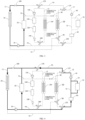
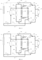
FIG. 1 is a schematic structural diagram of the vehicle thermal management system according to an embodiment of the present invention; -
FIG. 2 is a schematic structural diagram of the vehicle thermal management system according to another embodiment of the present invention, wherein the solenoid valve inFIG. 1 is replaced by a one-way valve; -
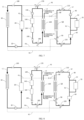
FIG. 3 is a schematic structural diagram of the vehicle thermal management system according to an embodiment of the present invention, wherein the vehicle thermal management system is in the first mode, and the heavy solid lines and the arrows in the figure represent the flowing paths and the flowing directions of the coolant in that mode; -
FIG. 4 is a schematic structural diagram of the vehicle thermal management system according to an embodiment of the present invention, wherein the vehicle thermal management system is in the second mode, and the heavy solid lines and the arrows in the figure represent the flowing paths and the flowing directions of the coolant in that mode; -
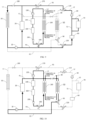
FIG. 5 is a schematic structural diagram of the vehicle thermal management system according to an embodiment of the present invention, wherein the vehicle thermal management system is in the third mode, and the heavy solid lines and the arrows in the figure represent the flowing paths and the flowing directions of the coolant in that mode; -
FIG. 6 is a schematic structural diagram of the vehicle thermal management system according to an embodiment of the present invention, wherein the vehicle thermal management system is in the fourth mode, and the heavy solid lines and the arrows in the figure represent the flowing paths and the flowing directions of the coolant in that mode; -
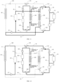
FIG. 7 is a schematic structural diagram of the vehicle thermal management system according to an embodiment of the present invention, wherein the vehicle thermal management system is in the fifth mode, and the heavy solid lines and the arrows in the figure represent the flowing paths and the flowing directions of the coolant in that mode; -
FIG. 8 is a schematic structural diagram of the vehicle thermal management system according to an embodiment of the present invention, wherein the vehicle thermal management system is in the sixth mode, and the heavy solid lines and the arrows in the figure represent the flowing paths and the flowing directions of the coolant in that mode; -
FIG. 9 is a schematic structural diagram of the vehicle thermal management system according to an embodiment of the present invention, wherein the vehicle thermal management system is in the seventh mode, and the heavy solid lines and the arrows in the figure represent the flowing paths and the flowing directions of the coolant in that mode; -
FIG. 10 is a schematic structural diagram of the vehicle thermal management system according to an embodiment of the present invention, wherein the vehicle thermal management system is in the eighth mode, and the heavy solid lines and the arrows in the figure represent the flowing paths and the flowing directions of the coolant in that mode; -
FIG. 11 is a schematic structural diagram of the vehicle thermal management system according to an embodiment of the present invention, wherein the vehicle thermal management system is in the ninth mode, and the heavy solid lines and the arrows in the figure represent the flowing paths and the flowing directions of the coolant in that mode; -
FIG. 12 is a schematic structural diagram of the vehicle thermal management system according to an embodiment of the present invention, wherein the vehicle thermal management system is in the tenth mode, and the heavy solid lines and the arrows in the figure represent the flowing paths and the flowing directions of the coolant in that mode; -
FIG. 13 is a schematic structural diagram of the vehicle thermal management system according to an embodiment of the present invention, wherein the vehicle thermal management system is in the eleventh mode, and the heavy solid lines and the arrows in the figure represent the flowing paths and the flowing directions of the coolant in that mode; and -
FIG. 14 is a schematic structural diagram of the vehicle thermal management system according to an embodiment of the present invention, wherein the vehicle thermal management system is in the twelfth mode, and the heavy solid lines and the arrows in the figure represent the flowing paths and the flowing directions of the coolant in that mode. - 10-first water pump; 20-motor; 30-radiator; 40-second water pump; 50-first heat exchanger; 60-battery; 70-charger; 80-first switching valve; 90-second switching valve; 100-third switching valve; 110-first three-way valve; 120-second three-way valve; 130-third water pump; 140-heater; 150-heater core; 160-second heat exchanger; 170-third three-way valve; 180-fourth three-way valve; 190-fourth switching valve; L1-first coolant loop; L2-second coolant loop; L3-third coolant loop; F1-first flow path; F2-second flow path; F3-third flow path; F4-fourth flow path; S1-first branch; and S2-second branch.
- The particular embodiments of the present invention will be described in detail below with reference to the drawings. It should be understood that the particular embodiments described herein are merely intended to describe and interpret the present invention, and are not intended to limit the present invention.
- As shown in
FIG. 1 to FIG. 14 , the present invention provides a vehicle thermal management system. The vehicle thermal management system comprises a first coolant loop L1, a second coolant loop L2, a first flow path F1, and a second flow path F2. Afirst water pump 10, amotor 20, and aradiator 30 are provided in the first coolant loop L1. Asecond water pump 40, abattery 60, and afirst heat exchanger 50 are provided in the second coolant loop L2, and thefirst heat exchanger 50 is further located in a refrigerant flow path of an air conditioning system of the vehicle; in other words, thefirst heat exchanger 50 is located in both of the first coolant loop L2 and the air conditioning system of the vehicle. One end of the first flow path F1 is connected to a coolant outlet of themotor 20 and the other end is connected to a coolant inlet of thefirst heat exchanger 50, and one end of the second flow path F2 is connected to a coolant outlet of thefirst heat exchanger 50 and the other end is connected to a coolant inlet of thefirst water pump 10, whereby a motor-waste-heat recovery mode is provided in the vehicle thermal management system, to provide heat to a refrigerant in the refrigerant flow path in the motor-waste-heat-recovery mode. - A
first switching valve 80 is provided between the coolant outlet of themotor 20 and the coolant inlet of thefirst heat exchanger 50, and asecond switching valve 90 is provided between the coolant outlet of thefirst heat exchanger 50 and the coolant inlet of thefirst water pump 10, and in the motor-waste-heat-recovery mode, as shown inFIG. 1 and FIG. 2 , the flow path of the coolant is: thefirst water pump 10 → themotor 20 → thefirst switching valve 80 → thefirst heat exchanger 50 → thesecond switching valve 90 → thefirst water pump 10. - In the vehicle thermal management system according to the present invention, the
motor 20 and thebattery 60 are located in the two coolant loops, i.e., the first coolant loop L1 and the second coolant loop L2, and the two coolant loops may operate independently. For example, theradiator 30 is used to solely realize the heat dissipation of themotor 20, or thefirst heat exchanger 50 is used to exchange heat with the air conditioning system, to solely realize the heating to thebattery 60. In addition, because the first flow path F1 and the second flow path F2 are provided to connect the first coolant loop L1 and the second coolant loop L2, the two coolant loops may be connected to operate, to realize the motor-waste-heat-recovery mode stated above. In other words, by communicating the two coolant loops, the waste heat of themotor 20 may be provided to thebattery 60, to heat thebattery 60. Moreover, by communicating the two coolant loops, by using thefirst heat exchanger 50, the heat exchange between the vehicle air conditioning system and thebattery 60 and/or themotor 20 may be realized. Therefore, the configuration is conducive to reduce the quantities of the parts of the vehicle thermal management system and reduce the cost. - Particularly, the thermal management system provided by the present invention is capable of cooling or heating the
battery 60 and/or themotor 20 by using the cold energy or heat of the air conditioning system through thefirst heat exchanger 50, to ensure that thebattery 60 and/or themotor 20 may operate within the appropriate temperature ranges. Furthermore, the vehicle thermal management system may also realize the enthalpy increase of the refrigerant in the air conditioning system by using the heat of themotor 20 through thefirst heat exchanger 50, to increase the suction temperature and the suction pressure of the compressor, thereby improving the heating capacity of the air conditioning system in a low-temperature environment. - Furthermore, it may be known from the above that, in the motor-waste-heat-recovery mode, the coolant passes through a small number of parts in the flowing process, and is not required to pass through the parts that lead to a large heat loss, which is conducive to provide waste heat of the
motor 20 to thefirst heat exchanger 50 as much as possible, so as to provide the heat to thebattery 60 as much as possible. - Optionally, as shown in
FIG. 1 and FIG. 2 , thefirst switching valve 80 may be provided in the first flow path F1, the second flow path F2 is bypass connected to the second coolant loop L2 via thesecond switching valve 90, and thesecond switching valve 90 is a three-way valve, whereby thesecond switching valve 90 is capable of realizing an on-off switch of the second flow path F2 and an on-off switch of the second coolant loop L2. Particularly, as shown inFIG. 1 , thesecond switching valve 90 communicates with the second flow path F2 via the port A1, and is connected to the second coolant loop L2 via the port B1 and the port C1. - In the present embodiment, because the
first switching valve 80 is provided in the first flow path F1, thefirst switching valve 80 may be a common switching valve (for example, the solenoid valve shown inFIG. 1 ) or a one-way valve (as shown inFIG. 2 ). - The
second switching valve 90 is a three-way valve, and it may not only control the on-off switch of the second flow path F2, but also may control the on-off switch of the second coolant loop L2. Thesecond switching valve 90 controls the on-off switch of a plurality of the coolant flow paths, which is conducive to reduce the quantities of the parts, and reduce the cost. In addition, because thesecond switching valve 90 is a three-way valve, by controlling the on-off switch of thesecond switching valve 90, multiple different operation modes may be realized (which may be particularly seen below). - It may be understood that, in the other embodiments, the
first switching valve 80 may be a three-way valve, and the first flow path F1 is bypass connected to the second coolant loop L2 via thefirst switching valve 80. Thesecond switching valve 90 may be a common two-way valve and is located in the second flow path F2. - Optionally, as shown in
FIG. 1 and FIG. 2 , athird switching valve 100 may be provided in the first coolant loop L1, and thethird switching valve 100 is provided between themotor 20 and theradiator 30, to realize the on-off switch of the first coolant loop L1. Accordingly, by switching on or switching off thethird switching valve 100, different operation modes may be realized. For example, when the motor-waste-heat-recovery mode is required, the third switching valve may be used to cut off the first coolant loop L1, to prevent theradiator 30 located in the first coolant loop L1 from affecting the recovery of the waste heat of the motor. - Optionally, as shown in
FIG. 1 and FIG. 2 , in the second coolant loop L2, a first branch S1 and a second branch S2 may be connected in parallel between thebattery 60 and thesecond water pump 40. The first branch S1 is short-circuit-connected between thebattery 60 and thesecond water pump 40, and an electronic device is provided in the second branch S2, wherein the electronic device may comprise at least one of acharger 70, a motor controller, and a DC-DC converter. - In the present embodiment, by providing the two branches, in an aspect, when the
battery 60 is required to be heated, part of the coolant may not pass through the electronic device, which is conducive to increase the efficiency of the heating to thebattery 60. In another aspect, when it is required to cool thecharger 70, the configuration also ensures that part of the coolant may flow through thecharger 70 to cool it. Furthermore, such a configuration may not only ensure the cooling to thecharger 70, but also avoid the provision of a switching valve in the first branch S1 and the second branch S2, which is conducive to reduce the use of the parts, which is conducive to simplify the structure of the system, and may reduce the cost. - Optionally, the flow size of the second branch S2 is less than the flow size of the first branch S1, whereby the flow rate of the coolant flowing through the second branch S2 is capable of being less than the flow rate of the coolant flowing through the first branch S1. A low amount of the coolant is required because the heat output of the electronic device is relatively small, Therefore, the second branch S2 may be used to deliver the coolant of a relatively small flow rate to the electronic device.
- It may be understood that, in the other embodiments, switching valves may be provided in the first branch S1 and/or the second branch S2, to realize an active control on the on-off switch of the first branch S1 and/or the second branch S2.
- As shown in
FIG. 1 and FIG. 2 , the vehicle thermal management system according to the invention, further comprises a first three-way valve 110, a second three-way valve 120, a third flow path F3 and a fourth flow path F4. Both of the first three-way valve 110 and the second three-way valve 120 are provided in the second coolant loop L2 and are located on a coolant inlet side and a coolant outlet side of thefirst heat exchanger 50, respectively. In other words, the first three-way valve 110 is connected to the second coolant loop L2 via the port A2 and the port B2, and the second three-way valve 120 is connected to the second coolant loop L2 via the port A3 and the port B3. One remaining port (the port C2) of the first three-way valve 110 is connected to the first coolant loop L1 via the third flow path F3, and one remaining port (the port C3) of the second three-way valve 120 is connected to the first coolant loop L1 via the fourth flow path F4. - As shown in
FIG. 1 and FIG. 2 , the connection point of the fourth flow path F4 and the first coolant loop L1 and the connection point of the third flow path F3 and the first coolant loop L1 are located on a coolant inlet side and a coolant outlet side of themotor 20, respectively, whereby the vehicle thermal management system is capable of heating thebattery 60 by using heat of themotor 20, or cooling thebattery 60 by using theradiator 30. - Optionally, as shown in
FIG. 1 and FIG. 2 , the vehicle thermal management system may further comprise a third coolant loop L3, athird water pump 130, aheater 140, and anheater core 150 are provided in the third coolant loop L3, theheater core 150 is for heating the cabin of the vehicle by using theheater 140, and the third coolant loop L3 is connected to the first coolant loop L1 and the second coolant loop L2 by flow paths, whereby the third coolant loop L3 is capable of solely operating, or being connected to one of the first coolant loop L1 and the second coolant loop L2 to operate, or being connected to both of the first coolant loop L1 and the second coolant loop L2 to operate. In other words, in the present embodiment, the three coolant loops may operate solely, and may also operate jointly, to realize multiple operation modes. - In addition, in an aspect, such a configuration is conducive to the heat exchange among the first coolant loop L1, the second coolant loop L2 and the coolant loop L3, for example, using the recovered waste heat of the
motor 20 for the heating to the cabin. In another aspect, such a configuration is conducive to reduce the quantities of the parts of the vehicle thermal management system, which is conducive to reduce the cost. - The
heater 140 may be any type of heater that may heat the coolant. For example,heater 140 may be a PTC heater (including an air-warming-type PTC heater and a water-warming-type PTC heater) or an HVCH heater (high-pressure coolant heater), and the particular type of theheater 10 is not limited in the present disclosure. - Optionally, as shown in
FIG. 1 and FIG. 2 , asecond heat exchanger 160 may be provided in the third coolant loop L3, and thesecond heat exchanger 160 is further located in the refrigerant flow path of the air conditioning system. By providing thesecond heat exchanger 160, the heat exchange between the third coolant loop L3 and the air conditioning system may be performed. For example, the third coolant loop L3 absorbs the heat of the air conditioning system to be used to heat the cabin, the heat of theheater 140 may be transferred to the cabin by using theheater core 150, and the heat of the air conditioning system may be transferred to the cabin via thesecond heat exchanger 160 and by using theheater core 150, to heat the cabin. Theheater 140 operates as an auxiliary heating source, and the air conditioning system operates as the primary heating source, to provide the heat to theheater core 150 via thesecond heat exchanger 160. Therefore, according to the cabin heating demand, the air conditioning system and theheater 140 may supply heat at the same time, and merely one of them may also be used to supply heat. For example, when the ambient temperature is low, when the air conditioning system is insufficient to satisfy the cabin heating, theheater 140 may be started up or both of them may be started up at the same time to ensure the heat of the cabin. Moreover, when the ambient temperature is not very low, starting up merely the air conditioning system may satisfy cabin heating. Alternatively, thesecond heat exchanger 160 may also absorb the heat of the air conditioning system to heat the battery, in which case the heater core may not be required to be started up. - As an alternative embodiment, the
second heat exchanger 160 may be used as a condenser in the air conditioning system, to exchange heat with the air conditioning (heat pump) system, to increase the temperature of the coolant in the third coolant loop L3, to supply heat to the cabin. - Optionally, in another embodiment, the
second heat exchanger 160 may be used as an evaporator to heat the refrigerant in the air conditioning system by using the temperature of the coolant in the third coolant loop L3. - Optionally, as shown in
FIG. 1 and FIG. 2 , the vehicle thermal management system may further comprise a third three-way valve 170 and a fourth three-way valve 180, the third three-way valve 170 is provided in the third flow path F3, or, in other words, the third three-way valve 170 is connected to the third flow path F3 via the port A4 and the port B4, and one remaining port (the port C4) of the third three-way valve 170 is connected to the third coolant loop L3 by a flow path. The fourth three-way valve 180 is provided in the third coolant loop L3, or, in other words, the fourth three-way valve 180 is connected to the fourth flow path F4 via the port A5 and the port B5, and one remaining port (the port C5) of the fourth three-way valve 180 is connected to the fourth flow path F4 by a flow path. The connection point of the fourth three-way valve 180 and the third coolant loop L3 and the connection point of the third three-way valve 170 and the third coolant loop L3 are located on a coolant inlet side and a coolant outlet side of thesecond heat exchanger 160, respectively. - By providing the third three-way valve and the fourth three-way valve, the third coolant loop L3 is connected to the first coolant loop L1 and the second coolant loop L2. Furthermore, by controlling the on-off switch of the third three-
way valve 170 and the fourth three-way valve 180, different operation modes may be realized, which may be particularly seen below. - Optionally, as shown in
FIG. 1 and FIG. 2 , afourth switching valve 190 is provided in the third coolant loop L3, and thefourth switching valve 190 is located between theheater core 150 and the fourth three-way valve 180, to realize the on-off switch of the third coolant loop L3. Therefore, according to demands, thefourth switching valve 190 may be switched on or switched off according to practical demands, to realize the corresponding operation modes. For example, when thesecond heat exchanger 160 operates as a condenser to perform heat dissipation to the air conditioning system, the third coolant loop L3 may be cut off by switching off thefourth switching valve 190, thereby preventing the heat of thesecond heat exchanger 160 from entering theheater core 150, which affects the temperature of the cabin. Optionally, thefourth switching valve 190 may be a one-way valve, and the one-way valve allows the coolant to flow from theheater core 150 to thesecond heat exchanger 160 and the fourth three-way valve 180. - The main operation modes and the circulation processes and the principles in the corresponding operation modes of the vehicle thermal management system will be described in detail below by taking the embodiment in
FIG. 1 as an example with reference to FIG. 3 to FIG. 15. - The first mode is a mode in which the
radiator 30 is used to cool themotor 20. In this mode, as shown inFIG. 3 , thefirst water pump 10, themotor 20, and theradiator 30 form one circulation loop. In this case, the flow path of the coolant is: thefirst water pump 10 → themotor 20 → thethird switching valve 100 → theradiator 30 → thefirst water pump 10. Accordingly, the coolant exchanges heat with the external environment by using theradiator 30, to reduce the temperature of the coolant, thereby cooling themotor 20. - The second mode is a mode in which the
radiator 30 is used to cool themotor 20 and thebattery 60 at the same time. As shown inFIG. 4 , in this mode, thefirst water pump 10, themotor 20, and theradiator 30 form one circulation loop. Thefirst water pump 10, thebattery 60, thecharger 70, thesecond water pump 40, and theradiator 30 form one circulation loop. - Particularly, in this case, there are two loops in the flow path of the coolant. In the first loop, the flow path of the coolant is: the
first water pump 10 → themotor 20 → thethird switching valve 100 → theradiator 30 → thefirst water pump 10. In the second loop, the flow path of the coolant is: thesecond water pump 40 → the first three-way valve 110 (the port A2 communicates with the port C2) → the third three-way valve 170 (the port B4 communicates with the port A4) → thethird switching valve 100 → theradiator 30 → thefirst water pump 10 → the second three-way valve 120 (the port C3 communicates with the port B3) → thebattery 60 → thecharger 70 / the first branch S1 → thesecond water pump 40. Accordingly, the coolant exchanges heat with the external environment by using theradiator 30, to reduce the temperature of the coolant, thereby cooling themotor 20 and thebattery 60. - The third mode is a mode in which the
radiator 30 is used to cool themotor 20, thebattery 60, and the refrigerant in the air conditioning system at the same time. As shown inFIG. 5 , in this mode, thefirst water pump 10, themotor 20, and theradiator 30 form one circulation loop. Thefirst water pump 10, thebattery 60, thecharger 70, thesecond water pump 40, and theradiator 30 form one circulation loop. Thefirst water pump 10, thesecond heat exchanger 160, and theradiator 30 form one circulation loop. - Particularly, in this case, there are three loops in the flow path of the coolant. In the first loop, the flow path of the coolant is: the
first water pump 10 → themotor 20 → thethird switching valve 100 → theradiator 30 → thefirst water pump 10. In the second loop, the flow path of the coolant is: thesecond water pump 40 → the first three-way valve 110 (the port A2 communicates with the port C2) → the third three-way valve 170 (the port B4 communicates with the port A4) → thethird switching valve 100 → theradiator 30 → thefirst water pump 10 → the second three-way valve (the port C3 communicates with the port B3) → thebattery 60 → thecharger 70 / the first branch S1 → thesecond water pump 40. In the third loop, the flow path of the coolant is: thefirst water pump 10 → the fourth three-way valve 180 (the port C5 communicates with the port B5) → thesecond heat exchanger 160 → the third three-way valve 170 (the port C4 communicates with the port B4) → thethird switching valve 100 → theradiator 30 → thefirst water pump 10. Accordingly, the coolant exchanges heat with the external environment by using theradiator 30, to reduce the temperature of the coolant, thereby cooling themotor 20, thebattery 60, and the refrigerant in the air conditioning system. - The fourth mode is a mode in which the
radiator 30 is used to cool themotor 20 and the refrigerant in the air conditioning system at the same time, and thefirst heat exchanger 50 is used to cool thebattery 60. As shown inFIG. 6 , in this mode, thefirst water pump 10, themotor 20, and theradiator 30 form one circulation loop. Thefirst water pump 10, thesecond heat exchanger 160, and theradiator 30 form one circulation loop. The second coolant loop L2 operates. - Particularly, in this case, there are three loops in the flow path of the coolant. In the first loop, the flow path of the coolant is: the
first water pump 10 → themotor 20 → thethird switching valve 100 → theradiator 30 → thefirst water pump 10. In the second loop, the flow path of the coolant is: thefirst water pump 10 → the fourth three-way valve 180 (the port C5 communicates with the port B5) → thesecond heat exchanger 160 → the third three-way valve 170 (the port C4 communicates with the port B4) → thethird switching valve 100 → theradiator 30 → thefirst water pump 10. Accordingly, the coolant exchanges heat with the external environment by using theradiator 30, to reduce the temperature of the coolant, thereby cooling themotor 20 and the refrigerant in the air conditioning system. In the third loop, the flow path of the coolant is: thesecond water pump 40 → the first three-way valve 110 (the port A2 communicates with the port B2) → thefirst heat exchanger 50 → the second switching valve 90 (the port B1 communicates with the port C1) → the second three-way valve 120 (the port A3 communicates with the port B3) → thebattery 60 → thecharger 70/the first branch S1 - thesecond water pump 40. In this case, thefirst heat exchanger 50 exchanges heat with the refrigerant in the vehicle air conditioning system, to realize the cooling of thebattery 60. At the same time, the waste heat of thebattery 60 and thecharger 70 recovered in the air conditioning system may be used to increase the enthalpy of the air conditioning system, and to improve the capacity of the air conditioning system. - The fifth mode is a mode in which the
radiator 30 is used to cool themotor 20, theheater 140 and the air conditioning system are used to heat the cabin, and thebattery 60 maintains a constant temperature. As shown inFIG. 7 , in this mode, thefirst water pump 10, themotor 20, and theradiator 30 form one circulation loop. The second coolant loop L2 operates. Thethird water pump 130, theheater 140, theheater core 150, and thesecond heat exchanger 160 form one circulation loop. - Particularly, in this case, there are three loops in the flow path of the coolant. In the first loop, the flow path of the coolant is: the
first water pump 10 → themotor 20 → thethird switching valve 100 → theradiator 30 → thefirst water pump 10. Accordingly, the coolant exchanges heat with the external environment by using theradiator 30, to reduce the temperature of the coolant, thereby cooling themotor 20. In the second loop, the flow path of the coolant is: thesecond water pump 40 → the first three-way valve 110 (the port A2 communicates with the port B2) → thefirst heat exchanger 50 → the second switching valve 90 (the port B1 communicates with and the port C1) → the second three-way valve 120 (the port A3 communicates with and the port B3) → thebattery 60 → thecharger 70/the first branch S1 → thesecond water pump 40. In this case, thefirst heat exchanger 50 does not exchange heat with the vehicle air conditioning system, to maintain thebattery 60 to be in the constant-temperature mode to the largest extent. In the third loop, the flow path of the coolant is: thethird water pump 130 → theheater 140 → theheater core 150 → thefourth switching valve 190 → the fourth three-way valve 180 (the port A5 communicates with and the port B5) → thesecond heat exchanger 160 → thethird water pump 130. Accordingly, the heat of theheater 140 may be transferred to the cabin by using theheater core 150, and the heat of the air conditioning system may be transferred to the cabin via thesecond heat exchanger 160 and by using theheater core 150, to heat the cabin. Theheater 140 may operate as an auxiliary heating source, and the air conditioning system may operate as the primary heating source. - The sixth mode is a mode in which the
radiator 30 is used to cool themotor 20, theheater 140 and the air conditioning system are used to heat the cabin, and thefirst heat exchanger 50 is used to recover the waste heat of thebattery 60. As shown inFIG. 8 , in this mode, thefirst water pump 10, themotor 20, and theradiator 30 form one circulation loop. The second coolant loop L2 operates. Thethird water pump 130, theheater 140, theheater core 150, and thesecond heat exchanger 160 form one circulation loop. - Particularly, in this case, there are three loops in the flow path of the coolant. In the first loop, the flow path of the coolant is: the
first water pump 10 → themotor 20 → thethird switching valve 100 → theradiator 30 → thefirst water pump 10. Accordingly, the coolant exchanges heat with the external environment by using theradiator 30, to reduce the temperature of the coolant, thereby cooling themotor 20. In the second loop, the flow path of the coolant is: thesecond water pump 40 → the first three-way valve 110 (the port A2 communicates with the port B2) → thefirst heat exchanger 50 → the second switching valve 90 (the port B1 communicates with the port C1) → the second three-way valve 120 (the port A3 communicates with the port B3) → thebattery 60 → thecharger 70/the first branch S1 → thesecond water pump 40. In this case, thefirst heat exchanger 50 exchanges heat with the vehicle air conditioning system, and recovers the waste heat of thebattery 60 and thecharger 70, to be used to increase the enthalpy of the air conditioning system, to improve the capacity of the air conditioning system. At the same time, that cools thebattery 60. In the third loop, the flow path of the coolant is: thethird water pump 130 → theheater 140 → theheater core 150 → thefourth switching valve 190 → the fourth three-way valve 180 (the port A5 communicates with the port B5) → thesecond heat exchanger 160 → thethird water pump 130. Accordingly, the heat of theheater 140 may be transferred to the cabin by using theheater core 150, and the heat of the air conditioning system may be transferred to the cabin via thesecond heat exchanger 160 and by using theheater core 150, to heat the cabin. Theheater 140 may operate as an auxiliary heating source, and the air conditioning system may operate as the primary heating source. - The seventh mode is a mode in which the
radiator 30 is used to cool themotor 20 and thebattery 60 at the same time, and theheater 140 and the air conditioning system are used to heat the cabin. As shown inFIG. 9 , in this mode, thefirst water pump 10, themotor 20, and theradiator 30 form one circulation loop. Thefirst water pump 10, thebattery 60, thecharger 70, thesecond water pump 40, and theradiator 30 form one circulation loop. Thethird water pump 130, theheater 140, theheater core 150, and thesecond heat exchanger 160 form one circulation loop. - Particularly, in this case, there are three loops in the flow path of the coolant. In the first loop, the flow path of the coolant is: the
first water pump 10 → themotor 20 → thethird switching valve 100 → theradiator 30 → thefirst water pump 10. In the second loop, the flow path of the coolant is: thesecond water pump 40 → the first three-way valve 110 (the port A2 communicates with the port C2) → the third three-way valve 170 (the port B4 communicates with the port A4) → thethird switching valve 100 → theradiator 30 → thefirst water pump 10 → the second three-way valve 120 (the port C3 communicates with the port B3) → thebattery 60 → thecharger 70/the first branch S1 → thesecond water pump 40. Accordingly, the coolant exchanges heat with the external environment by using theradiator 30, to reduce the temperature of the coolant, thereby cooling themotor 20 and thebattery 60. In the third loop, the flow path of the coolant is: thethird water pump 130 → theheater 140 → theheater core 150 → thefourth switching valve 190 → the fourth three-way valve 180 (the port A5 communicates with the port B5) → thesecond heat exchanger 160 → thethird water pump 130. Accordingly, the heat of theheater 140 may be transferred to the cabin by using theheater core 150, and the heat of the air conditioning system may be transferred to the cabin via thesecond heat exchanger 160 and by using theheater core 150, to heat the cabin. Theheater 140 may operate as an auxiliary heating source, and the air conditioning system may operate as the primary heating source. - The eighth mode is a mode in which the
heater 140 and the air conditioning system are used to heat the cabin, and the waste heat of the motor is recovered. As shown inFIG. 10 , in this mode, thethird water pump 130, theheater 140, theheater core 150, and thesecond heat exchanger 160 form one circulation loop. Thefirst water pump 10, thefirst heat exchanger 50, and themotor 20 form one circulation loop. - Particularly, in this case, there are two loops in the flow path of the coolant. In the first loop, the flow path of the coolant is: the
third water pump 130 → theheater 140 → theheater core 150 → thefourth switching valve 190 → the fourth three-way valve 180 (the port A5 communicates with the port B5) → thesecond heat exchanger 160 → thethird water pump 130. Accordingly, the heat of theheater 140 may be transferred to the cabin by using theheater core 150, and the heat of the air conditioning system may be transferred to the cabin via thesecond heat exchanger 160 and by using theheater core 150, to heat the cabin. Theheater 140 may operate as an auxiliary heating source, and the air conditioning system may operate as the primary heating source. In the second loop, the flow path of the coolant is: thefirst water pump 10 → themotor 20 → thefirst switching valve 80 → thefirst heat exchanger 150 → the second switching valve 90 (the port B1 communicates with the port A1) → thefirst water pump 10. Accordingly, the waste heat of themotor 20 may be recovered into the air conditioning system by using thefirst heat exchanger 50, to be used to increase the enthalpy of the air conditioning system, and to improve the capacity of the air conditioning system. - The ninth mode is a mode in which the
heater 140 and the air conditioning system are used to heat the cabin, and thefirst heat exchanger 50 is used to recover the waste heat of themotor 20 and cool thebattery 60. As shown inFIG. 11 , in this mode, thethird water pump 130, theheater 140, theheater core 150, and thesecond heat exchanger 160 form one circulation loop. Thefirst water pump 10, thefirst heat exchanger 50, and themotor 20 form one circulation loop. Thesecond water pump 40, thefirst heat exchanger 50, thefirst water pump 10, thebattery 60, and thecharger 70 form one cooling circuit. - Particularly, in this case, there are three loops in the flow path of the coolant. In the first loop, the flow path of the coolant is: the
third water pump 130 → theheater 140 → theheater core 150 → thefourth switching valve 190 → the fourth three-way valve 180 (the port A5 communicates with the port B5) → thesecond heat exchanger 160 → thethird water pump 130. Accordingly, the heat of theheater 140 may be transferred to the cabin by using theheater core 150, and the heat of the air conditioning system may be transferred to the cabin via thesecond heat exchanger 160 and by using theheater core 150, to heat the cabin. Theheater 140 may operate as an auxiliary heating source, and the air conditioning system may operate as the primary heating source. In the second loop, the flow path of the coolant is: thefirst water pump 10 → themotor 20 → thefirst switching valve 80 → thefirst heat exchanger 50 → the second switching valve 90 (the port B1 communicates with the port A1) → thefirst water pump 10. Accordingly, the waste heat of themotor 20 may be recovered into the air conditioning system by using thefirst heat exchanger 50, to be used to increase the enthalpy of the air conditioning system, and to improve the capacity of the air conditioning system. In the third loop, the flow path of the coolant is: thesecond water pump 40 → the first three-way valve 110 (the port A2 communicates with the port B2) → thefirst heat exchanger 50 → the second switching valve 90 (the port B1 communicates with the port A1) → thefirst water pump 10 → the second three-way valve 120 (the port C3 communicates with the port B3) → thebattery 60 → thecharger 70/the first branch S1 → thesecond water pump 40. In this case, thefirst heat exchanger 50 exchanges heat with the vehicle air conditioning system, to reduce the temperature of the coolant in the second coolant loop L2, thereby cooling thebattery 60. At the same time, thefirst heat exchanger 50 supplies the heat of thebattery 60 to the air conditioning system, to be used to increase the enthalpy of the air conditioning system, and to improve the capacity of the air conditioning system. - The tenth mode is a mode in which the
radiator 30 is used to cool themotor 20, and theheater 140, and the air conditioning system are used to heat the cabin, and thebattery 60. As shown inFIG. 12 , in this mode, thefirst water pump 10, themotor 20, and theradiator 30 form one circulation loop. Thethird water pump 130, theheater 140, theheater core 150, and thesecond heat exchanger 160 form one circulation loop. Thesecond water pump 40, thethird water pump 130, theheater 140, theheater core 150, and thebattery 60 form one cooling circuit. - Particularly, in this case, there are three loops in the flow path of the coolant. In the first loop, the flow path of the coolant is: the
first water pump 10 → themotor 20 → thethird switching valve 100 → theradiator 30 → thefirst water pump 10. Accordingly, for example, theradiator 30 exchanges heat with the external environment, to reduce the temperature of the coolant, thereby cooling themotor 20. In the second loop, the flow path of the coolant is: thethird water pump 130 → theheater 140 → theheater core 150 → thefourth switching valve 190 → the fourth three-way valve 180 (the port A5 communicates with the port B5) → thesecond heat exchanger 160 → thethird water pump 130. Accordingly, the heat of theheater 140 may be transferred to the cabin by using theheater core 150, and the heat of the air conditioning system may be transferred to the cabin via thesecond heat exchanger 160 and by using theheater core 150, to heat the cabin. Theheater 140 may operate as an auxiliary heating source, and the air conditioning system may operate as the primary heating source. In the third loop, thesecond water pump 40 → the first three-way valve 110 (the port A2 communicates with the port C2) → the third three-way valve 170 (the port A4 communicates with the port C4) → thethird water pump 130 → theheater 140 → theheater core 150 → thefourth switching valve 190 → the fourth three-way valve 180 (the port A5 communicates with the port C5) → the second three-way valve (the port C3 communicates with the port B3) → thebattery 60 → thecharger 70/the first branch S1 → thesecond water pump 40. In this case, theheater 140 and the air conditioning system are used to heat thebattery 60. - The eleventh mode is a mode in which the
first heat exchanger 50 is used to recover the waste heat of themotor 20, and theheater 140 and the air conditioning system are used to heat the cabin and thebattery 60. As shown inFIG. 13 , thefirst water pump 10, thefirst heat exchanger 50, and themotor 20 form one circulation loop. Thethird water pump 130, theheater 140, theheater core 150, and thesecond heat exchanger 160 form one circulation loop. Thesecond water pump 40, thethird water pump 130, theheater 140, theheater core 150, and thebattery 60 form one cooling circuit. - Particularly, in this case, there are three loops in the flow path of the coolant. In the first loop, the flow path of the coolant is: the
first water pump 10 → themotor 20 → thefirst switching valve 80 → thefirst heat exchanger 150 → the second switching valve 90 (the port B1 communicates with the port A1) → thefirst water pump 10. Accordingly, the waste heat of themotor 20 may be recovered into the air conditioning system by using thefirst heat exchanger 50, to be used to increase the enthalpy of the air conditioning system, and to improve the capacity of the air conditioning system. In the second loop, the flow path of the coolant is: thethird water pump 130 → theheater 140 → theheater core 150 → thefourth switching valve 190 → the fourth three-way valve 180 (the port A5 communicates with the port B5) → thesecond heat exchanger 160 → thethird water pump 130. Accordingly, the heat of theheater 140 may be transferred to the cabin by using theheater core 150, and the heat of the air conditioning system may be transferred to the cabin via thesecond heat exchanger 160 and by using theheater core 150, to heat the cabin. Theheater 140 operates as an auxiliary heating source, and the air conditioning system operates as the primary heating source. In the third loop, thesecond water pump 40 → the first three-way valve 110 (the port A2 communicates with the port C2) → the third three-way valve 170 (the port A4 communicates with the port C4) → thethird water pump 130 → theheater 140 → theheater core 150 → thefourth switching valve 190 → the fourth three-way valve 180 (the port A5 communicates with and the port C5) → the second three-way valve (the port C3 communicates with the port B3) → thebattery 60 → thecharger 70/the first branch S1 → thesecond water pump 40. In this case, theheater 140 and the air conditioning system are used to heat thebattery 60. - The twelfth mode is a mode in which the
radiator 30 is used to cool themotor 20, thefirst heat exchanger 50 is used to recover the waste heat of themotor 20, and theheater 140 and the air conditioning system are used to heat the cabin and thebattery 60. As shown inFIG. 14 , in this mode, thefirst water pump 10, themotor 20 and theradiator 30 form one circulation loop. Thefirst water pump 10, thefirst heat exchanger 50 and themotor 20 form one circulation loop. Thethird water pump 130, theheater 140, theheater core 150, and thesecond heat exchanger 160 form one circulation loop. Thesecond water pump 40, thethird water pump 130, theheater 140, theheater core 150, and thebattery 60 form one cooling circuit. - Particularly, in this case, there are four loops in the flow path of the coolant. In the first loop, the flow path of the coolant is: the
first water pump 10 → themotor 20 → thethird switching valve 100 → theradiator 30 → thefirst water pump 10. Accordingly, for example, theradiator 30 exchanges heat with the external environment, to reduce the temperature of the coolant, thereby cooling themotor 20. In the second loop, the flow path of the coolant is: thefirst water pump 10 → themotor 20 → thefirst switching valve 80 → thefirst heat exchanger 150 → the second switching valve 90 (the port B1 communicates with the port A1) → thefirst water pump 10. Accordingly, the waste heat of themotor 20 may be recovered into the air conditioning system by using thefirst heat exchanger 50, to be used to increase the enthalpy of the air conditioning system, and to improve the capacity of the air conditioning system. In the third loop, the flow path of the coolant is: thethird water pump 130 → theheater 140 → theheater core 150 → thefourth switching valve 190 → the fourth three-way valve 180 (the port A5 communicates with the port B5) → thesecond heat exchanger 160 → thethird water pump 130. Accordingly, the heat of theheater 140 may be transferred to the cabin by using theheater core 150, and the heat of the air conditioning system may be transferred to the cabin via thesecond heat exchanger 160 and by using theheater core 150, to heat the cabin. Theheater 140 operates as an auxiliary heating source, and the air conditioning system operates as the primary heating source. In the fourth loop, thesecond water pump 40 → the first three-way valve 110 (the port A2 communicates with the port C2) → the third three-way valve 170 (the port A4 communicates with the port C4) → thethird water pump 130 → theheater 140 → theheater core 150 → thefourth switching valve 190 → the fourth three-way valve 180 (the port A5 communicates with the port C5) → the second three-way valve (the port C3 communicates with and the port B3) → thebattery 60 → thecharger 70/the first branch S1 → thesecond water pump 40. In this case, theheater 140 and the air conditioning system are used to heat thebattery 60. - According to another aspect of the present invention, there is provided a vehicle, wherein the vehicle comprises the vehicle thermal management system stated above.
- The preferable embodiments of the present invention have been described in detail above with reference to the drawings. However, the present invention is not limited to the particular details of the above embodiments but is limited only by the scope of the appended claims.
- In addition, it should be noted that the particular technical features described in the particular embodiments, subject to no contradiction, may be combined in any feasible way. In order to avoid unnecessary repeating, the feasible modes of combination will not be described further herein.
Claims (11)
- A vehicle thermal management system, comprising:a first coolant loop (L1), wherein a first water pump (10), a motor (20), and a radiator (30) are provided in the first coolant loop (L1);a second coolant loop (L2), wherein a second water pump (40), a battery (60), and a first heat exchanger (50) are provided in the second coolant loop (L2), and the first heat exchanger (50) is further located in a refrigerant flow path of an air conditioning system of a vehicle; anda first flow path (F1) and a second flow path (F2), wherein one end of the first flow path (F1) is connected to a coolant outlet of the motor (20), and the other end is connected to a coolant inlet of the first heat exchanger (50), and one end of the second flow path (F2) is connected to a coolant outlet of the first heat exchanger (50) and the other end is connected to a coolant inlet of the first water pump (10), whereby, in a motor-waste-heat-recovery mode, the vehicle thermal management system is capable of heating a refrigerant in the refrigerant flow path by using heat of the motor (20);wherein a first switching valve (80) is provided between the coolant outlet of the motor (20) and the coolant inlet of the first heat exchanger (50), and a second switching valve (90) is provided between the coolant outlet of the first heat exchanger (50) and the coolant inlet of the first water pump (10), whereby, in the motor-waste-heat-recovery mode, the vehicle thermal management system is capable of providing a flow path of a coolant: the first water pump (10) → the motor (20) → the first switching valve (80) → the first heat exchanger (50) → the second switching valve (90) → the first water pump (10);characterized in that the vehicle thermal management system further comprises a first three-way valve (110), a second three-way valve (120), a third flow path (F3) and a fourth flow path (F4);both of the first three-way valve (110) and the second three-way valve (120) are provided in the second coolant loop (L2) and are located at a coolant inlet side and a coolant outlet side of the first heat exchanger (50), respectively, one remaining port of the first three-way valve (110) is connected to the first coolant loop (L1) via the third flow path (F3), and one remaining port of the second three-way valve (120) is connected to the first coolant loop (L1) via the fourth flow path (F4); anda connection point of the fourth flow path (F4) and the first coolant loop (L1) and a connection point of the third flow path (F3) and the first coolant loop (L1) are located on a coolant inlet side and a coolant outlet side of the motor (20), respectively, whereby the vehicle thermal management system is capable of heating the battery (60) by using heat of the motor (20), or cooling the battery (60) by using the radiator (30).
- The vehicle thermal management system according to claim 1, characterized in that, the first switching valve (80) is provided in the first flow path (F1); and
the second flow path (F2) is bypass connected to the second coolant loop (L2) via the second switching valve (90), and the second switching valve (90) is a three-way valve, whereby the second switching valve (90) is capable of realizing an on-off switch of the second flow path (F2) and an on-off switch of the second coolant loop (L2). - The vehicle thermal management system according to claim 1, characterized in that, a third switching valve (100) is provided in the first coolant loop (L1), and the third switching valve (100) is provided between the motor (20) and the radiator (30), to realize an on-off switch of the first coolant loop (L1).
- The vehicle thermal management system according to claim 1, characterized in that, in the second coolant loop (L2), a first branch (S1) and a second branch (S2) are connected in parallel between the battery (60) and the second water pump (40);the first branch (S1) is short-circuit connected between the battery (60) and the second water pump (40); andan electronic device is provided in the second branch (S2), wherein the electronic device comprises at least one of a charger (70), a motor controller, and a DC-DC converter.
- The vehicle thermal management system according to claim 4, characterized in that, a flow size of the second branch (S2) is less than a flow size of the first branch (S1), whereby a flow rate of a coolant flowing through the second branch (S2) is capable of being less than a flow rate of a coolant flowing through the first branch (S1).
- The vehicle thermal management system according to claim 1-5, characterized in that, the vehicle thermal management system further comprises a third coolant loop (L3), a third water pump (130), a heater (140), and an heater core (150) are provided in the third coolant loop (L3), the heater core (150) is for heating a cabin of the vehicle by using the heater (140), and the third coolant loop (L3) is connected to the first coolant loop (L1) and the second coolant loop (L2) by flow paths, whereby the third coolant loop (L3) is capable of solely operating, or being connected to one of the first coolant loop (L1) and the second coolant loop (L2) to operate, or being connected to both of the first coolant loop (L1) and the second coolant loop (L2) to operate.
- The vehicle thermal management system according to claim 6, characterized in that, a second heat exchanger (160) is provided in the third coolant loop (L3), and the second heat exchanger (160) is further located in the refrigerant flow path of the air conditioning system.
- The vehicle thermal management system according to claim 7, characterized in that, the second heat exchanger (160) is configured as a condenser in the air conditioning system.
- The vehicle thermal management system according to claim 7, characterized in that, the vehicle thermal management system further comprises a third three-way valve (170) and a fourth three-way valve (180);the third three-way valve (170) is provided in the third flow path (F3), and one remaining port of the third three-way valve (170) is connected to the third coolant loop (L3) by a flow path;the fourth three-way valve (180) is provided in the third coolant loop (L3), and one remaining port of the fourth three-way valve (180) is connected to the fourth flow path (F4) by a flow path; anda connection point of the fourth three-way valve (180) and the third coolant loop (L3) and a connection point of the third three-way valve (170) and the third coolant loop (L3) are located on a coolant inlet side and a coolant outlet side of the second heat exchanger (160), respectively.
- The vehicle thermal management system according to claim 9, characterized in that, a fourth switching valve (190) is provided in the third coolant loop (L3), and the fourth switching valve (190) is located between the heater core (150) and the fourth three-way valve (180), to realize an on-off switch of the third coolant loop (L3).
- A vehicle, characterized in that, the vehicle comprises the vehicle thermal management system according to any one of claims 1-10.
Applications Claiming Priority (2)
| Application Number | Priority Date | Filing Date | Title |
|---|---|---|---|
| CN202110573390.1A CN113291143B (en) | 2021-05-25 | 2021-05-25 | Vehicle thermal management system and vehicle |
| PCT/CN2022/091254 WO2022247602A1 (en) | 2021-05-25 | 2022-05-06 | Vehicle thermal management system and vehicle |
Publications (3)
| Publication Number | Publication Date |
|---|---|
| EP4116119A1 EP4116119A1 (en) | 2023-01-11 |
| EP4116119A4 EP4116119A4 (en) | 2023-09-27 |
| EP4116119B1 true EP4116119B1 (en) | 2025-04-30 |
Family
ID=77325082
Family Applications (1)
| Application Number | Title | Priority Date | Filing Date |
|---|---|---|---|
| EP22761345.2A Active EP4116119B1 (en) | 2021-05-25 | 2022-05-06 | Vehicle thermal management system and vehicle |
Country Status (3)
| Country | Link |
|---|---|
| EP (1) | EP4116119B1 (en) |
| CN (1) | CN113291143B (en) |
| WO (1) | WO2022247602A1 (en) |
Families Citing this family (11)
| Publication number | Priority date | Publication date | Assignee | Title |
|---|---|---|---|---|
| JP7623840B2 (en) * | 2021-01-13 | 2025-01-29 | 本田技研工業株式会社 | Vehicle temperature control system |
| CN113291143B (en) * | 2021-05-25 | 2025-03-11 | 曼德电子电器有限公司 | Vehicle thermal management system and vehicle |
| CN114030391A (en) * | 2021-12-14 | 2022-02-11 | 阿波罗智能技术(北京)有限公司 | Autonomous driving vehicle and heat recovery system, control method and control device thereof |
| CN116487767A (en) * | 2022-12-27 | 2023-07-25 | 镇江海姆霍兹传热传动系统有限公司 | Electric heater, thermal management system, electric vehicle and energy storage system |
| CN219883646U (en) * | 2023-01-10 | 2023-10-24 | 法雷奥汽车空调湖北有限公司 | Thermal management system for a vehicle |
| CN116330919A (en) * | 2023-02-14 | 2023-06-27 | 无锡星驱动力科技有限公司 | Thermal management system and thermal management method |
| CN116278606B (en) * | 2023-03-22 | 2026-01-09 | 无锡星驱动力科技有限公司 | Thermal management system and thermal management methods |
| CN116176360A (en) * | 2023-03-30 | 2023-05-30 | 上海加冷松芝汽车空调股份有限公司 | An electric vehicle thermal management system and the electric vehicle |
| DE102023118019A1 (en) * | 2023-07-07 | 2025-01-09 | Bayerische Motoren Werke Aktiengesellschaft | Temperature control device for a motor vehicle, in particular for a motor vehicle, and motor vehicle with such a temperature control device |
| FR3160010A1 (en) * | 2024-03-08 | 2025-09-12 | Valeo Systemes Thermiques | Thermal conditioning system |
| CN119388947B (en) * | 2024-10-28 | 2025-10-31 | 奇瑞汽车股份有限公司 | Thermal management system and vehicle |
Family Cites Families (16)
| Publication number | Priority date | Publication date | Assignee | Title |
|---|---|---|---|---|
| FR2995669B1 (en) * | 2012-09-14 | 2018-05-25 | Valeo Systemes Thermiques | DEVICE FOR THERMALLY CONDITIONING A HABITACLE OF AN ELECTRIC VEHICLE |
| KR101836272B1 (en) * | 2016-06-20 | 2018-03-08 | 현대자동차 주식회사 | Heat pump system for vehicle |
| FR3057494B1 (en) * | 2016-10-13 | 2019-07-26 | Hutchinson | INSTALLATION OF THERMAL CONDITIONING OF A CAR AND / OR AT LEAST ONE ORGAN OF A MOTOR VEHICLE |
| WO2019062553A1 (en) * | 2017-09-29 | 2019-04-04 | 爱驰汽车有限公司 | Automobile thermal management system, and automobile having same |
| CN107946693A (en) * | 2017-12-05 | 2018-04-20 | 珠海长欣汽车智能系统有限公司 | A kind of automobile refrigerating cooling system |
| KR102530943B1 (en) * | 2018-07-25 | 2023-05-11 | 현대자동차주식회사 | Thermal management system for vehicle |
| CN111231620B (en) * | 2018-11-29 | 2022-05-13 | 比亚迪股份有限公司 | Vehicle thermal management system, control method thereof and vehicle |
| DE102019100096B4 (en) * | 2019-01-04 | 2021-01-28 | Hanon Systems | Air conditioning and battery cooling arrangement as well as method for operating an air conditioning and battery cooling arrangement |
| JP7099392B2 (en) * | 2019-04-03 | 2022-07-12 | トヨタ自動車株式会社 | In-vehicle temperature control device |
| CN110356195A (en) * | 2019-08-08 | 2019-10-22 | 宜宾凯翼汽车有限公司 | A kind of electrombile thermal management system and method |
| CN112208294A (en) * | 2020-09-21 | 2021-01-12 | 东风汽车集团有限公司 | Electric automobile heat management system based on waste heat recovery and control method thereof |
| CN213228245U (en) * | 2020-09-29 | 2021-05-18 | 蜂巢能源科技有限公司 | Vehicle thermal management system and vehicle |
| CN112158053A (en) * | 2020-09-29 | 2021-01-01 | 曼德电子电器有限公司 | Vehicle thermal management system and vehicle |
| CN112158054A (en) * | 2020-09-29 | 2021-01-01 | 曼德电子电器有限公司 | Vehicle thermal management system and vehicle |
| CN214874175U (en) * | 2021-05-25 | 2021-11-26 | 曼德电子电器有限公司 | Vehicle thermal management system and vehicle |
| CN113291143B (en) * | 2021-05-25 | 2025-03-11 | 曼德电子电器有限公司 | Vehicle thermal management system and vehicle |
-
2021
- 2021-05-25 CN CN202110573390.1A patent/CN113291143B/en active Active
-
2022
- 2022-05-06 WO PCT/CN2022/091254 patent/WO2022247602A1/en not_active Ceased
- 2022-05-06 EP EP22761345.2A patent/EP4116119B1/en active Active
Also Published As
| Publication number | Publication date |
|---|---|
| EP4116119A1 (en) | 2023-01-11 |
| EP4116119A4 (en) | 2023-09-27 |
| WO2022247602A1 (en) | 2022-12-01 |
| CN113291143A (en) | 2021-08-24 |
| CN113291143B (en) | 2025-03-11 |
Similar Documents
| Publication | Publication Date | Title |
|---|---|---|
| EP4116119B1 (en) | Vehicle thermal management system and vehicle | |
| EP4197832A1 (en) | Electric vehicle thermal management loop, control method, and pure electric vehicle | |
| CN112277559B (en) | Coolant liquid thermal control module, electric motor car thermal management system and electric motor car | |
| AU2022356849B2 (en) | Thermal management system and vehicle having same | |
| CN118046742A (en) | Vehicle thermal management system and vehicle | |
| US20240255196A1 (en) | Energy storage and charging station | |
| CN113580872B (en) | Vehicles and their thermal management systems | |
| US11358438B2 (en) | Automotive air conditioning system | |
| CN118061731A (en) | Integrated waste heat recovery CO2 heat pump thermal management system for new energy vehicles | |
| WO2024065221A1 (en) | Thermal management system and vehicle | |
| KR20230158861A (en) | Integrated thermal management system for fuel cell vehicle | |
| CN219096440U (en) | Vehicle thermal management system and vehicle | |
| EP4043250B1 (en) | Vehicle thermal management system, and vehicle | |
| CN214874175U (en) | Vehicle thermal management system and vehicle | |
| CN216401111U (en) | Vehicle thermal management system and vehicle | |
| CN212289436U (en) | Thermal management system and electric automobile | |
| CN212386273U (en) | Vehicle thermal management system and vehicle | |
| CN212637096U (en) | Vehicle thermal management system and vehicle | |
| CN118494105A (en) | Vehicle thermal management system and vehicle | |
| CN216886149U (en) | Coolant side system for heat pump, heat pump system and vehicle | |
| CN111750561B (en) | Heat pump system | |
| CN219415055U (en) | Heat pump air conditioning system | |
| CN114435061A (en) | Vehicle thermal management systems and vehicles | |
| CN222451896U (en) | Indirect heat pump system | |
| CN223443262U (en) | Thermal management system |
Legal Events
| Date | Code | Title | Description |
|---|---|---|---|
| STAA | Information on the status of an ep patent application or granted ep patent |
Free format text: STATUS: UNKNOWN |
|
| STAA | Information on the status of an ep patent application or granted ep patent |
Free format text: STATUS: THE INTERNATIONAL PUBLICATION HAS BEEN MADE |
|
| PUAI | Public reference made under article 153(3) epc to a published international application that has entered the european phase |
Free format text: ORIGINAL CODE: 0009012 |
|
| STAA | Information on the status of an ep patent application or granted ep patent |
Free format text: STATUS: REQUEST FOR EXAMINATION WAS MADE |
|
| 17P | Request for examination filed |
Effective date: 20220908 |
|
| AK | Designated contracting states |
Kind code of ref document: A1 Designated state(s): AL AT BE BG CH CY CZ DE DK EE ES FI FR GB GR HR HU IE IS IT LI LT LU LV MC MK MT NL NO PL PT RO RS SE SI SK SM TR |
|
| A4 | Supplementary search report drawn up and despatched |
Effective date: 20230824 |
|
| RIC1 | Information provided on ipc code assigned before grant |
Ipc: B60K 11/02 20060101ALI20230818BHEP Ipc: B60K 1/00 20060101ALI20230818BHEP Ipc: B60L 58/26 20190101ALI20230818BHEP Ipc: B60H 1/32 20060101ALI20230818BHEP Ipc: B60H 1/14 20060101ALI20230818BHEP Ipc: B60L 58/24 20190101ALI20230818BHEP Ipc: B60H 1/00 20060101AFI20230818BHEP |
|
| DAV | Request for validation of the european patent (deleted) | ||
| DAX | Request for extension of the european patent (deleted) | ||
| GRAP | Despatch of communication of intention to grant a patent |
Free format text: ORIGINAL CODE: EPIDOSNIGR1 |
|
| STAA | Information on the status of an ep patent application or granted ep patent |
Free format text: STATUS: GRANT OF PATENT IS INTENDED |
|
| INTG | Intention to grant announced |
Effective date: 20250211 |
|
| GRAS | Grant fee paid |
Free format text: ORIGINAL CODE: EPIDOSNIGR3 |
|
| GRAA | (expected) grant |
Free format text: ORIGINAL CODE: 0009210 |
|
| STAA | Information on the status of an ep patent application or granted ep patent |
Free format text: STATUS: THE PATENT HAS BEEN GRANTED |
|
| AK | Designated contracting states |
Kind code of ref document: B1 Designated state(s): AL AT BE BG CH CY CZ DE DK EE ES FI FR GB GR HR HU IE IS IT LI LT LU LV MC MK MT NL NO PL PT RO RS SE SI SK SM TR |
|
| REG | Reference to a national code |
Ref country code: CH Ref legal event code: EP Ref country code: GB Ref legal event code: FG4D |
|
| REG | Reference to a national code |
Ref country code: IE Ref legal event code: FG4D |
|
| REG | Reference to a national code |
Ref country code: DE Ref legal event code: R096 Ref document number: 602022013985 Country of ref document: DE |
|
| P01 | Opt-out of the competence of the unified patent court (upc) registered |
Free format text: CASE NUMBER: APP_24837/2025 Effective date: 20250523 |
|
| PGFP | Annual fee paid to national office [announced via postgrant information from national office to epo] |
Ref country code: DE Payment date: 20250617 Year of fee payment: 4 |
|
| PGFP | Annual fee paid to national office [announced via postgrant information from national office to epo] |
Ref country code: FR Payment date: 20250530 Year of fee payment: 4 |
|
| PGFP | Annual fee paid to national office [announced via postgrant information from national office to epo] |
Ref country code: AT Payment date: 20250721 Year of fee payment: 4 |
|
| REG | Reference to a national code |
Ref country code: NL Ref legal event code: MP Effective date: 20250430 |
|
| REG | Reference to a national code |
Ref country code: AT Ref legal event code: MK05 Ref document number: 1789729 Country of ref document: AT Kind code of ref document: T Effective date: 20250430 |
|
| PG25 | Lapsed in a contracting state [announced via postgrant information from national office to epo] |
Ref country code: ES Free format text: LAPSE BECAUSE OF FAILURE TO SUBMIT A TRANSLATION OF THE DESCRIPTION OR TO PAY THE FEE WITHIN THE PRESCRIBED TIME-LIMIT Effective date: 20250430 Ref country code: PT Free format text: LAPSE BECAUSE OF FAILURE TO SUBMIT A TRANSLATION OF THE DESCRIPTION OR TO PAY THE FEE WITHIN THE PRESCRIBED TIME-LIMIT Effective date: 20250901 Ref country code: FI Free format text: LAPSE BECAUSE OF FAILURE TO SUBMIT A TRANSLATION OF THE DESCRIPTION OR TO PAY THE FEE WITHIN THE PRESCRIBED TIME-LIMIT Effective date: 20250430 |
|
| REG | Reference to a national code |
Ref country code: LT Ref legal event code: MG9D |
|
| PG25 | Lapsed in a contracting state [announced via postgrant information from national office to epo] |
Ref country code: GR Free format text: LAPSE BECAUSE OF FAILURE TO SUBMIT A TRANSLATION OF THE DESCRIPTION OR TO PAY THE FEE WITHIN THE PRESCRIBED TIME-LIMIT Effective date: 20250731 Ref country code: NO Free format text: LAPSE BECAUSE OF FAILURE TO SUBMIT A TRANSLATION OF THE DESCRIPTION OR TO PAY THE FEE WITHIN THE PRESCRIBED TIME-LIMIT Effective date: 20250730 |
|
| PG25 | Lapsed in a contracting state [announced via postgrant information from national office to epo] |
Ref country code: NL Free format text: LAPSE BECAUSE OF FAILURE TO SUBMIT A TRANSLATION OF THE DESCRIPTION OR TO PAY THE FEE WITHIN THE PRESCRIBED TIME-LIMIT Effective date: 20250430 Ref country code: PL Free format text: LAPSE BECAUSE OF FAILURE TO SUBMIT A TRANSLATION OF THE DESCRIPTION OR TO PAY THE FEE WITHIN THE PRESCRIBED TIME-LIMIT Effective date: 20250430 |
|
| PG25 | Lapsed in a contracting state [announced via postgrant information from national office to epo] |
Ref country code: BG Free format text: LAPSE BECAUSE OF FAILURE TO SUBMIT A TRANSLATION OF THE DESCRIPTION OR TO PAY THE FEE WITHIN THE PRESCRIBED TIME-LIMIT Effective date: 20250430 |
|
| PG25 | Lapsed in a contracting state [announced via postgrant information from national office to epo] |
Ref country code: AT Free format text: LAPSE BECAUSE OF FAILURE TO SUBMIT A TRANSLATION OF THE DESCRIPTION OR TO PAY THE FEE WITHIN THE PRESCRIBED TIME-LIMIT Effective date: 20250430 Ref country code: HR Free format text: LAPSE BECAUSE OF FAILURE TO SUBMIT A TRANSLATION OF THE DESCRIPTION OR TO PAY THE FEE WITHIN THE PRESCRIBED TIME-LIMIT Effective date: 20250430 |
|
| PG25 | Lapsed in a contracting state [announced via postgrant information from national office to epo] |
Ref country code: RS Free format text: LAPSE BECAUSE OF FAILURE TO SUBMIT A TRANSLATION OF THE DESCRIPTION OR TO PAY THE FEE WITHIN THE PRESCRIBED TIME-LIMIT Effective date: 20250731 |
|
| PG25 | Lapsed in a contracting state [announced via postgrant information from national office to epo] |
Ref country code: IS Free format text: LAPSE BECAUSE OF FAILURE TO SUBMIT A TRANSLATION OF THE DESCRIPTION OR TO PAY THE FEE WITHIN THE PRESCRIBED TIME-LIMIT Effective date: 20250830 |
|
| PG25 | Lapsed in a contracting state [announced via postgrant information from national office to epo] |
Ref country code: LV Free format text: LAPSE BECAUSE OF FAILURE TO SUBMIT A TRANSLATION OF THE DESCRIPTION OR TO PAY THE FEE WITHIN THE PRESCRIBED TIME-LIMIT Effective date: 20250430 |
|
| REG | Reference to a national code |
Ref country code: CH Ref legal event code: H13 Free format text: ST27 STATUS EVENT CODE: U-0-0-H10-H13 (AS PROVIDED BY THE NATIONAL OFFICE) Effective date: 20251223 |
|
| PG25 | Lapsed in a contracting state [announced via postgrant information from national office to epo] |
Ref country code: SM Free format text: LAPSE BECAUSE OF FAILURE TO SUBMIT A TRANSLATION OF THE DESCRIPTION OR TO PAY THE FEE WITHIN THE PRESCRIBED TIME-LIMIT Effective date: 20250430 Ref country code: DK Free format text: LAPSE BECAUSE OF FAILURE TO SUBMIT A TRANSLATION OF THE DESCRIPTION OR TO PAY THE FEE WITHIN THE PRESCRIBED TIME-LIMIT Effective date: 20250430 |
|
| PG25 | Lapsed in a contracting state [announced via postgrant information from national office to epo] |
Ref country code: LU Free format text: LAPSE BECAUSE OF NON-PAYMENT OF DUE FEES Effective date: 20250506 |
|
| PG25 | Lapsed in a contracting state [announced via postgrant information from national office to epo] |
Ref country code: CH Free format text: LAPSE BECAUSE OF NON-PAYMENT OF DUE FEES Effective date: 20250531 |
|
| PG25 | Lapsed in a contracting state [announced via postgrant information from national office to epo] |
Ref country code: CZ Free format text: LAPSE BECAUSE OF FAILURE TO SUBMIT A TRANSLATION OF THE DESCRIPTION OR TO PAY THE FEE WITHIN THE PRESCRIBED TIME-LIMIT Effective date: 20250430 |
|
| PG25 | Lapsed in a contracting state [announced via postgrant information from national office to epo] |
Ref country code: EE Free format text: LAPSE BECAUSE OF FAILURE TO SUBMIT A TRANSLATION OF THE DESCRIPTION OR TO PAY THE FEE WITHIN THE PRESCRIBED TIME-LIMIT Effective date: 20250430 |
|
| PG25 | Lapsed in a contracting state [announced via postgrant information from national office to epo] |
Ref country code: SK Free format text: LAPSE BECAUSE OF FAILURE TO SUBMIT A TRANSLATION OF THE DESCRIPTION OR TO PAY THE FEE WITHIN THE PRESCRIBED TIME-LIMIT Effective date: 20250430 |
|
| PG25 | Lapsed in a contracting state [announced via postgrant information from national office to epo] |
Ref country code: IT Free format text: LAPSE BECAUSE OF FAILURE TO SUBMIT A TRANSLATION OF THE DESCRIPTION OR TO PAY THE FEE WITHIN THE PRESCRIBED TIME-LIMIT Effective date: 20250430 |
|
| PG25 | Lapsed in a contracting state [announced via postgrant information from national office to epo] |
Ref country code: MC Free format text: LAPSE BECAUSE OF FAILURE TO SUBMIT A TRANSLATION OF THE DESCRIPTION OR TO PAY THE FEE WITHIN THE PRESCRIBED TIME-LIMIT Effective date: 20250430 |
|
| PLBI | Opposition filed |
Free format text: ORIGINAL CODE: 0009260 |
|
| PG25 | Lapsed in a contracting state [announced via postgrant information from national office to epo] |
Ref country code: RO Free format text: LAPSE BECAUSE OF FAILURE TO SUBMIT A TRANSLATION OF THE DESCRIPTION OR TO PAY THE FEE WITHIN THE PRESCRIBED TIME-LIMIT Effective date: 20250430 |
|
| PLAX | Notice of opposition and request to file observation + time limit sent |
Free format text: ORIGINAL CODE: EPIDOSNOBS2 |
|
| REG | Reference to a national code |
Ref country code: CH Ref legal event code: L10 Free format text: ST27 STATUS EVENT CODE: U-0-0-L10-L00 (AS PROVIDED BY THE NATIONAL OFFICE) Effective date: 20260211 |