EP4116058A1 - Foaming and shaping process for a thermoplastic sheet, and associated apparatus and shaped foamed thermoplastic sheet - Google Patents
Foaming and shaping process for a thermoplastic sheet, and associated apparatus and shaped foamed thermoplastic sheet Download PDFInfo
- Publication number
- EP4116058A1 EP4116058A1 EP21184715.7A EP21184715A EP4116058A1 EP 4116058 A1 EP4116058 A1 EP 4116058A1 EP 21184715 A EP21184715 A EP 21184715A EP 4116058 A1 EP4116058 A1 EP 4116058A1
- Authority
- EP
- European Patent Office
- Prior art keywords
- metal plate
- weight percent
- polystyrene
- thermoplastic sheet
- combination
- Prior art date
- Legal status (The legal status is an assumption and is not a legal conclusion. Google has not performed a legal analysis and makes no representation as to the accuracy of the status listed.)
- Granted
Links
Images


Classifications
-
- B—PERFORMING OPERATIONS; TRANSPORTING
- B29—WORKING OF PLASTICS; WORKING OF SUBSTANCES IN A PLASTIC STATE IN GENERAL
- B29C—SHAPING OR JOINING OF PLASTICS; SHAPING OF MATERIAL IN A PLASTIC STATE, NOT OTHERWISE PROVIDED FOR; AFTER-TREATMENT OF THE SHAPED PRODUCTS, e.g. REPAIRING
- B29C44/00—Shaping by internal pressure generated in the material, e.g. swelling or foaming ; Producing porous or cellular expanded plastics articles
- B29C44/34—Auxiliary operations
- B29C44/3442—Mixing, kneading or conveying the foamable material
- B29C44/3446—Feeding the blowing agent
- B29C44/3453—Feeding the blowing agent to solid plastic material
-
- B—PERFORMING OPERATIONS; TRANSPORTING
- B29—WORKING OF PLASTICS; WORKING OF SUBSTANCES IN A PLASTIC STATE IN GENERAL
- B29C—SHAPING OR JOINING OF PLASTICS; SHAPING OF MATERIAL IN A PLASTIC STATE, NOT OTHERWISE PROVIDED FOR; AFTER-TREATMENT OF THE SHAPED PRODUCTS, e.g. REPAIRING
- B29C43/00—Compression moulding, i.e. applying external pressure to flow the moulding material; Apparatus therefor
- B29C43/003—Compression moulding, i.e. applying external pressure to flow the moulding material; Apparatus therefor characterised by the choice of material
-
- B—PERFORMING OPERATIONS; TRANSPORTING
- B29—WORKING OF PLASTICS; WORKING OF SUBSTANCES IN A PLASTIC STATE IN GENERAL
- B29C—SHAPING OR JOINING OF PLASTICS; SHAPING OF MATERIAL IN A PLASTIC STATE, NOT OTHERWISE PROVIDED FOR; AFTER-TREATMENT OF THE SHAPED PRODUCTS, e.g. REPAIRING
- B29C33/00—Moulds or cores; Details thereof or accessories therefor
- B29C33/42—Moulds or cores; Details thereof or accessories therefor characterised by the shape of the moulding surface, e.g. ribs or grooves
- B29C33/424—Moulding surfaces provided with means for marking or patterning
-
- B—PERFORMING OPERATIONS; TRANSPORTING
- B29—WORKING OF PLASTICS; WORKING OF SUBSTANCES IN A PLASTIC STATE IN GENERAL
- B29C—SHAPING OR JOINING OF PLASTICS; SHAPING OF MATERIAL IN A PLASTIC STATE, NOT OTHERWISE PROVIDED FOR; AFTER-TREATMENT OF THE SHAPED PRODUCTS, e.g. REPAIRING
- B29C43/00—Compression moulding, i.e. applying external pressure to flow the moulding material; Apparatus therefor
- B29C43/02—Compression moulding, i.e. applying external pressure to flow the moulding material; Apparatus therefor of articles of definite length, i.e. discrete articles
- B29C43/021—Compression moulding, i.e. applying external pressure to flow the moulding material; Apparatus therefor of articles of definite length, i.e. discrete articles characterised by the shape of the surface
-
- B—PERFORMING OPERATIONS; TRANSPORTING
- B29—WORKING OF PLASTICS; WORKING OF SUBSTANCES IN A PLASTIC STATE IN GENERAL
- B29C—SHAPING OR JOINING OF PLASTICS; SHAPING OF MATERIAL IN A PLASTIC STATE, NOT OTHERWISE PROVIDED FOR; AFTER-TREATMENT OF THE SHAPED PRODUCTS, e.g. REPAIRING
- B29C43/00—Compression moulding, i.e. applying external pressure to flow the moulding material; Apparatus therefor
- B29C43/32—Component parts, details or accessories; Auxiliary operations
-
- B—PERFORMING OPERATIONS; TRANSPORTING
- B29—WORKING OF PLASTICS; WORKING OF SUBSTANCES IN A PLASTIC STATE IN GENERAL
- B29C—SHAPING OR JOINING OF PLASTICS; SHAPING OF MATERIAL IN A PLASTIC STATE, NOT OTHERWISE PROVIDED FOR; AFTER-TREATMENT OF THE SHAPED PRODUCTS, e.g. REPAIRING
- B29C43/00—Compression moulding, i.e. applying external pressure to flow the moulding material; Apparatus therefor
- B29C43/32—Component parts, details or accessories; Auxiliary operations
- B29C43/36—Moulds for making articles of definite length, i.e. discrete articles
-
- B—PERFORMING OPERATIONS; TRANSPORTING
- B29—WORKING OF PLASTICS; WORKING OF SUBSTANCES IN A PLASTIC STATE IN GENERAL
- B29C—SHAPING OR JOINING OF PLASTICS; SHAPING OF MATERIAL IN A PLASTIC STATE, NOT OTHERWISE PROVIDED FOR; AFTER-TREATMENT OF THE SHAPED PRODUCTS, e.g. REPAIRING
- B29C43/00—Compression moulding, i.e. applying external pressure to flow the moulding material; Apparatus therefor
- B29C43/32—Component parts, details or accessories; Auxiliary operations
- B29C43/58—Measuring, controlling or regulating
-
- B—PERFORMING OPERATIONS; TRANSPORTING
- B29—WORKING OF PLASTICS; WORKING OF SUBSTANCES IN A PLASTIC STATE IN GENERAL
- B29C—SHAPING OR JOINING OF PLASTICS; SHAPING OF MATERIAL IN A PLASTIC STATE, NOT OTHERWISE PROVIDED FOR; AFTER-TREATMENT OF THE SHAPED PRODUCTS, e.g. REPAIRING
- B29C44/00—Shaping by internal pressure generated in the material, e.g. swelling or foaming ; Producing porous or cellular expanded plastics articles
- B29C44/34—Auxiliary operations
- B29C44/56—After-treatment of articles, e.g. for altering the shape
-
- B—PERFORMING OPERATIONS; TRANSPORTING
- B29—WORKING OF PLASTICS; WORKING OF SUBSTANCES IN A PLASTIC STATE IN GENERAL
- B29C—SHAPING OR JOINING OF PLASTICS; SHAPING OF MATERIAL IN A PLASTIC STATE, NOT OTHERWISE PROVIDED FOR; AFTER-TREATMENT OF THE SHAPED PRODUCTS, e.g. REPAIRING
- B29C44/00—Shaping by internal pressure generated in the material, e.g. swelling or foaming ; Producing porous or cellular expanded plastics articles
- B29C44/34—Auxiliary operations
- B29C44/56—After-treatment of articles, e.g. for altering the shape
- B29C44/5627—After-treatment of articles, e.g. for altering the shape by mechanical deformation, e.g. crushing, embossing, stretching
-
- B—PERFORMING OPERATIONS; TRANSPORTING
- B29—WORKING OF PLASTICS; WORKING OF SUBSTANCES IN A PLASTIC STATE IN GENERAL
- B29C—SHAPING OR JOINING OF PLASTICS; SHAPING OF MATERIAL IN A PLASTIC STATE, NOT OTHERWISE PROVIDED FOR; AFTER-TREATMENT OF THE SHAPED PRODUCTS, e.g. REPAIRING
- B29C44/00—Shaping by internal pressure generated in the material, e.g. swelling or foaming ; Producing porous or cellular expanded plastics articles
- B29C44/34—Auxiliary operations
- B29C44/56—After-treatment of articles, e.g. for altering the shape
- B29C44/5627—After-treatment of articles, e.g. for altering the shape by mechanical deformation, e.g. crushing, embossing, stretching
- B29C44/5636—After-treatment of articles, e.g. for altering the shape by mechanical deformation, e.g. crushing, embossing, stretching with the addition of heat
-
- B—PERFORMING OPERATIONS; TRANSPORTING
- B29—WORKING OF PLASTICS; WORKING OF SUBSTANCES IN A PLASTIC STATE IN GENERAL
- B29D—PRODUCING PARTICULAR ARTICLES FROM PLASTICS OR FROM SUBSTANCES IN A PLASTIC STATE
- B29D7/00—Producing flat articles, e.g. films or sheets
- B29D7/01—Films or sheets
-
- C—CHEMISTRY; METALLURGY
- C08—ORGANIC MACROMOLECULAR COMPOUNDS; THEIR PREPARATION OR CHEMICAL WORKING-UP; COMPOSITIONS BASED THEREON
- C08J—WORKING-UP; GENERAL PROCESSES OF COMPOUNDING; AFTER-TREATMENT NOT COVERED BY SUBCLASSES C08B, C08C, C08F, C08G or C08H
- C08J9/00—Working-up of macromolecular substances to porous or cellular articles or materials; After-treatment thereof
- C08J9/04—Working-up of macromolecular substances to porous or cellular articles or materials; After-treatment thereof using blowing gases generated by a previously added blowing agent
- C08J9/12—Working-up of macromolecular substances to porous or cellular articles or materials; After-treatment thereof using blowing gases generated by a previously added blowing agent by a physical blowing agent
-
- C—CHEMISTRY; METALLURGY
- C08—ORGANIC MACROMOLECULAR COMPOUNDS; THEIR PREPARATION OR CHEMICAL WORKING-UP; COMPOSITIONS BASED THEREON
- C08J—WORKING-UP; GENERAL PROCESSES OF COMPOUNDING; AFTER-TREATMENT NOT COVERED BY SUBCLASSES C08B, C08C, C08F, C08G or C08H
- C08J9/00—Working-up of macromolecular substances to porous or cellular articles or materials; After-treatment thereof
- C08J9/04—Working-up of macromolecular substances to porous or cellular articles or materials; After-treatment thereof using blowing gases generated by a previously added blowing agent
- C08J9/12—Working-up of macromolecular substances to porous or cellular articles or materials; After-treatment thereof using blowing gases generated by a previously added blowing agent by a physical blowing agent
- C08J9/122—Hydrogen, oxygen, CO2, nitrogen or noble gases
-
- C—CHEMISTRY; METALLURGY
- C08—ORGANIC MACROMOLECULAR COMPOUNDS; THEIR PREPARATION OR CHEMICAL WORKING-UP; COMPOSITIONS BASED THEREON
- C08J—WORKING-UP; GENERAL PROCESSES OF COMPOUNDING; AFTER-TREATMENT NOT COVERED BY SUBCLASSES C08B, C08C, C08F, C08G or C08H
- C08J9/00—Working-up of macromolecular substances to porous or cellular articles or materials; After-treatment thereof
- C08J9/36—After-treatment
-
- B—PERFORMING OPERATIONS; TRANSPORTING
- B29—WORKING OF PLASTICS; WORKING OF SUBSTANCES IN A PLASTIC STATE IN GENERAL
- B29C—SHAPING OR JOINING OF PLASTICS; SHAPING OF MATERIAL IN A PLASTIC STATE, NOT OTHERWISE PROVIDED FOR; AFTER-TREATMENT OF THE SHAPED PRODUCTS, e.g. REPAIRING
- B29C43/00—Compression moulding, i.e. applying external pressure to flow the moulding material; Apparatus therefor
- B29C43/02—Compression moulding, i.e. applying external pressure to flow the moulding material; Apparatus therefor of articles of definite length, i.e. discrete articles
- B29C43/021—Compression moulding, i.e. applying external pressure to flow the moulding material; Apparatus therefor of articles of definite length, i.e. discrete articles characterised by the shape of the surface
- B29C2043/023—Compression moulding, i.e. applying external pressure to flow the moulding material; Apparatus therefor of articles of definite length, i.e. discrete articles characterised by the shape of the surface having a plurality of grooves
-
- B—PERFORMING OPERATIONS; TRANSPORTING
- B29—WORKING OF PLASTICS; WORKING OF SUBSTANCES IN A PLASTIC STATE IN GENERAL
- B29C—SHAPING OR JOINING OF PLASTICS; SHAPING OF MATERIAL IN A PLASTIC STATE, NOT OTHERWISE PROVIDED FOR; AFTER-TREATMENT OF THE SHAPED PRODUCTS, e.g. REPAIRING
- B29C43/00—Compression moulding, i.e. applying external pressure to flow the moulding material; Apparatus therefor
- B29C43/32—Component parts, details or accessories; Auxiliary operations
- B29C2043/3205—Particular pressure exerting means for making definite articles
- B29C2043/3216—Particular pressure exerting means for making definite articles deformable nets, meshes, lattices or fabrics, e.g. tubular ones
-
- B—PERFORMING OPERATIONS; TRANSPORTING
- B29—WORKING OF PLASTICS; WORKING OF SUBSTANCES IN A PLASTIC STATE IN GENERAL
- B29C—SHAPING OR JOINING OF PLASTICS; SHAPING OF MATERIAL IN A PLASTIC STATE, NOT OTHERWISE PROVIDED FOR; AFTER-TREATMENT OF THE SHAPED PRODUCTS, e.g. REPAIRING
- B29C43/00—Compression moulding, i.e. applying external pressure to flow the moulding material; Apparatus therefor
- B29C43/32—Component parts, details or accessories; Auxiliary operations
- B29C43/36—Moulds for making articles of definite length, i.e. discrete articles
- B29C43/361—Moulds for making articles of definite length, i.e. discrete articles with pressing members independently movable of the parts for opening or closing the mould, e.g. movable pistons
- B29C2043/3615—Forming elements, e.g. mandrels or rams or stampers or pistons or plungers or punching devices
- B29C2043/3634—Forming elements, e.g. mandrels or rams or stampers or pistons or plungers or punching devices having specific surface shape, e.g. grooves, projections, corrugations
-
- B—PERFORMING OPERATIONS; TRANSPORTING
- B29—WORKING OF PLASTICS; WORKING OF SUBSTANCES IN A PLASTIC STATE IN GENERAL
- B29C—SHAPING OR JOINING OF PLASTICS; SHAPING OF MATERIAL IN A PLASTIC STATE, NOT OTHERWISE PROVIDED FOR; AFTER-TREATMENT OF THE SHAPED PRODUCTS, e.g. REPAIRING
- B29C43/00—Compression moulding, i.e. applying external pressure to flow the moulding material; Apparatus therefor
- B29C43/32—Component parts, details or accessories; Auxiliary operations
- B29C43/58—Measuring, controlling or regulating
- B29C2043/5833—Measuring, controlling or regulating movement of moulds or mould parts, e.g. opening or closing, actuating
-
- B—PERFORMING OPERATIONS; TRANSPORTING
- B29—WORKING OF PLASTICS; WORKING OF SUBSTANCES IN A PLASTIC STATE IN GENERAL
- B29K—INDEXING SCHEME ASSOCIATED WITH SUBCLASSES B29B, B29C OR B29D, RELATING TO MOULDING MATERIALS OR TO MATERIALS FOR MOULDS, REINFORCEMENTS, FILLERS OR PREFORMED PARTS, e.g. INSERTS
- B29K2071/00—Use of polyethers, e.g. PEEK, i.e. polyether-etherketone or PEK, i.e. polyetherketone or derivatives thereof, as moulding material
- B29K2071/12—PPO, i.e. polyphenylene oxide; PPE, i.e. polyphenylene ether
-
- B—PERFORMING OPERATIONS; TRANSPORTING
- B29—WORKING OF PLASTICS; WORKING OF SUBSTANCES IN A PLASTIC STATE IN GENERAL
- B29K—INDEXING SCHEME ASSOCIATED WITH SUBCLASSES B29B, B29C OR B29D, RELATING TO MOULDING MATERIALS OR TO MATERIALS FOR MOULDS, REINFORCEMENTS, FILLERS OR PREFORMED PARTS, e.g. INSERTS
- B29K2079/00—Use of polymers having nitrogen, with or without oxygen or carbon only, in the main chain, not provided for in groups B29K2061/00 - B29K2077/00, as moulding material
- B29K2079/08—PI, i.e. polyimides or derivatives thereof
- B29K2079/085—Thermoplastic polyimides, e.g. polyesterimides, PEI, i.e. polyetherimides, or polyamideimides; Derivatives thereof
-
- B—PERFORMING OPERATIONS; TRANSPORTING
- B29—WORKING OF PLASTICS; WORKING OF SUBSTANCES IN A PLASTIC STATE IN GENERAL
- B29K—INDEXING SCHEME ASSOCIATED WITH SUBCLASSES B29B, B29C OR B29D, RELATING TO MOULDING MATERIALS OR TO MATERIALS FOR MOULDS, REINFORCEMENTS, FILLERS OR PREFORMED PARTS, e.g. INSERTS
- B29K2105/00—Condition, form or state of moulded material or of the material to be shaped
- B29K2105/0005—Condition, form or state of moulded material or of the material to be shaped containing compounding ingredients
- B29K2105/0026—Flame proofing or flame retarding agents
-
- B—PERFORMING OPERATIONS; TRANSPORTING
- B29—WORKING OF PLASTICS; WORKING OF SUBSTANCES IN A PLASTIC STATE IN GENERAL
- B29K—INDEXING SCHEME ASSOCIATED WITH SUBCLASSES B29B, B29C OR B29D, RELATING TO MOULDING MATERIALS OR TO MATERIALS FOR MOULDS, REINFORCEMENTS, FILLERS OR PREFORMED PARTS, e.g. INSERTS
- B29K2105/00—Condition, form or state of moulded material or of the material to be shaped
- B29K2105/0088—Blends of polymers
-
- B—PERFORMING OPERATIONS; TRANSPORTING
- B29—WORKING OF PLASTICS; WORKING OF SUBSTANCES IN A PLASTIC STATE IN GENERAL
- B29K—INDEXING SCHEME ASSOCIATED WITH SUBCLASSES B29B, B29C OR B29D, RELATING TO MOULDING MATERIALS OR TO MATERIALS FOR MOULDS, REINFORCEMENTS, FILLERS OR PREFORMED PARTS, e.g. INSERTS
- B29K2105/00—Condition, form or state of moulded material or of the material to be shaped
- B29K2105/04—Condition, form or state of moulded material or of the material to be shaped cellular or porous
-
- B—PERFORMING OPERATIONS; TRANSPORTING
- B29—WORKING OF PLASTICS; WORKING OF SUBSTANCES IN A PLASTIC STATE IN GENERAL
- B29K—INDEXING SCHEME ASSOCIATED WITH SUBCLASSES B29B, B29C OR B29D, RELATING TO MOULDING MATERIALS OR TO MATERIALS FOR MOULDS, REINFORCEMENTS, FILLERS OR PREFORMED PARTS, e.g. INSERTS
- B29K2995/00—Properties of moulding materials, reinforcements, fillers, preformed parts or moulds
- B29K2995/0012—Properties of moulding materials, reinforcements, fillers, preformed parts or moulds having particular thermal properties
-
- B—PERFORMING OPERATIONS; TRANSPORTING
- B29—WORKING OF PLASTICS; WORKING OF SUBSTANCES IN A PLASTIC STATE IN GENERAL
- B29L—INDEXING SCHEME ASSOCIATED WITH SUBCLASS B29C, RELATING TO PARTICULAR ARTICLES
- B29L2031/00—Other particular articles
- B29L2031/34—Electrical apparatus, e.g. sparking plugs or parts thereof
- B29L2031/3468—Batteries, accumulators or fuel cells
-
- C—CHEMISTRY; METALLURGY
- C08—ORGANIC MACROMOLECULAR COMPOUNDS; THEIR PREPARATION OR CHEMICAL WORKING-UP; COMPOSITIONS BASED THEREON
- C08J—WORKING-UP; GENERAL PROCESSES OF COMPOUNDING; AFTER-TREATMENT NOT COVERED BY SUBCLASSES C08B, C08C, C08F, C08G or C08H
- C08J2201/00—Foams characterised by the foaming process
- C08J2201/02—Foams characterised by the foaming process characterised by mechanical pre- or post-treatments
- C08J2201/032—Impregnation of a formed object with a gas
-
- C—CHEMISTRY; METALLURGY
- C08—ORGANIC MACROMOLECULAR COMPOUNDS; THEIR PREPARATION OR CHEMICAL WORKING-UP; COMPOSITIONS BASED THEREON
- C08J—WORKING-UP; GENERAL PROCESSES OF COMPOUNDING; AFTER-TREATMENT NOT COVERED BY SUBCLASSES C08B, C08C, C08F, C08G or C08H
- C08J2371/00—Characterised by the use of polyethers obtained by reactions forming an ether link in the main chain; Derivatives of such polymers
- C08J2371/08—Polyethers derived from hydroxy compounds or from their metallic derivatives
- C08J2371/10—Polyethers derived from hydroxy compounds or from their metallic derivatives from phenols
- C08J2371/12—Polyphenylene oxides
-
- C—CHEMISTRY; METALLURGY
- C08—ORGANIC MACROMOLECULAR COMPOUNDS; THEIR PREPARATION OR CHEMICAL WORKING-UP; COMPOSITIONS BASED THEREON
- C08J—WORKING-UP; GENERAL PROCESSES OF COMPOUNDING; AFTER-TREATMENT NOT COVERED BY SUBCLASSES C08B, C08C, C08F, C08G or C08H
- C08J2379/00—Characterised by the use of macromolecular compounds obtained by reactions forming in the main chain of the macromolecule a linkage containing nitrogen with or without oxygen, or carbon only, not provided for in groups C08J2361/00 - C08J2377/00
- C08J2379/04—Polycondensates having nitrogen-containing heterocyclic rings in the main chain; Polyhydrazides; Polyamide acids or similar polyimide precursors
- C08J2379/08—Polyimides; Polyester-imides; Polyamide-imides; Polyamide acids or similar polyimide precursors
-
- C—CHEMISTRY; METALLURGY
- C08—ORGANIC MACROMOLECULAR COMPOUNDS; THEIR PREPARATION OR CHEMICAL WORKING-UP; COMPOSITIONS BASED THEREON
- C08J—WORKING-UP; GENERAL PROCESSES OF COMPOUNDING; AFTER-TREATMENT NOT COVERED BY SUBCLASSES C08B, C08C, C08F, C08G or C08H
- C08J2425/00—Characterised by the use of homopolymers or copolymers of compounds having one or more unsaturated aliphatic radicals, each having only one carbon-to-carbon double bond, and at least one being terminated by an aromatic carbocyclic ring; Derivatives of such polymers
- C08J2425/02—Homopolymers or copolymers of hydrocarbons
- C08J2425/04—Homopolymers or copolymers of styrene
-
- C—CHEMISTRY; METALLURGY
- C08—ORGANIC MACROMOLECULAR COMPOUNDS; THEIR PREPARATION OR CHEMICAL WORKING-UP; COMPOSITIONS BASED THEREON
- C08J—WORKING-UP; GENERAL PROCESSES OF COMPOUNDING; AFTER-TREATMENT NOT COVERED BY SUBCLASSES C08B, C08C, C08F, C08G or C08H
- C08J2453/00—Characterised by the use of block copolymers containing at least one sequence of a polymer obtained by reactions only involving carbon-to-carbon unsaturated bonds; Derivatives of such polymers
- C08J2453/02—Characterised by the use of block copolymers containing at least one sequence of a polymer obtained by reactions only involving carbon-to-carbon unsaturated bonds; Derivatives of such polymers of vinyl aromatic monomers and conjugated dienes
Definitions
- Foaming of thermoplastics with supercritical carbon dioxide is a cost-effective and residue-free method of forming foamed thermoplastic sheets.
- a combination of a foaming step and a subsequent shaping step is commercially practiced primarily for thermoplastics with glass transition temperatures less than 0 °C, including polypropylenes, thermoplastic polyurethanes, ethylene-vinyl acetate copolymers, and polyester elastomers.
- foaming is conducted in a high-temperature foaming machine, then the foamed sheet is transferred to a separate room temperature machine for cooling and shaping. The process works well for thermoplastics with glass transition tem less than 0 °C, because the foamed sheets are still soft when they are transferred to the room temperature cooling and shaping machine.
- One embodiment is a method of foaming and shaping a thermoplastic sheet, comprising: foaming a thermoplastic sheet with supercritical carbon dioxide to form a foamed thermoplastic sheet; wherein the thermoplastic sheet comprises a thermoplastic composition comprising a poly(phenylene ether), a polyetherimide, or a combination thereof; and wherein the thermoplastic composition is characterized by a glass transition temperature of 20 to 300 °C determined by differential scanning calorimetry according to ASTM D3418-15 at heating rate of 20 °C/minute; and shaping the foamed thermoplastic sheet to form a shaped foamed thermoplastic sheet; wherein the shaping comprises compressing the foamed thermoplastic sheet between a first metal plate and a second metal plate; wherein a surface of the first metal plate and a surface of the second metal plate comprise a plurality of grooves, each groove having a width of 0.1 to 1 millimeter and a depth of 0.1 to 1 millimeter, and each groove being separated from the nearest groove by a center-to-center distance of
- Another embodiment is a shaped foamed thermoplastic sheet produced by the method in any of its variations described herein and comprising a plurality of projections corresponding to the plurality of grooves of the first metal plate and the second metal plate.
- Another embodiment is an electric vehicle battery comprising the shaped foamed thermoplastic sheet in any of its variations.
- Another embodiment is an apparatus for shaping a foamed thermoplastic sheet, comprising: a first metal plate and a second metal plate; wherein each of the first metal plate and the second metal plate comprises a thermoplastic-facing major surface; wherein the thermoplastic-facing major surface of the first metal plate or the second metal plate or both comprises a plurality of grooves, each groove having a width of 0.1 to 1 millimeter and a depth of 0.1 to 1 millimeter; and wherein the thermoplastic-facing major surface of the first metal plate or the second metal plate or both comprises a rigid spacer to control the minimum separation of the first metal plate and the second metal plate; a flexible linkage connecting the first metal plate and the second metal plate, the flexible linkage being capable of modulating a separation between the first metal plate and the second metal plate; and a hydraulic system capable of compressing the flexible linkage connecting the first metal plate and the second metal plate.
- thermoplastics having a glass transition temperature of at least 20 °C can be foamed with supercritical carbon dioxide, then cooled and shaped without cracking, surface deformation, non-uniform foamed sheet thickness, or non-uniform foamed sheet density by a process including a cooling and shaping step that utilizes grooved metal plates connected by a flexible linkage.
- one embodiment is a method of foaming and shaping a thermoplastic sheet, comprising: foaming a thermoplastic sheet with supercritical carbon dioxide to form a foamed thermoplastic sheet; wherein the thermoplastic sheet comprises a thermoplastic composition comprising a poly(phenylene ether), a polyetherimide, or a combination thereof; and wherein the thermoplastic composition is characterized by a glass transition temperature of 20 to 300 °C determined by differential scanning calorimetry according to ASTM D3418-15 at heating rate of 20 °C/minute; and shaping the foamed thermoplastic sheet to form a shaped foamed thermoplastic sheet; wherein the shaping comprises compressing the foamed thermoplastic sheet between a first metal plate and a second metal plate; wherein a surface of the first metal plate and a surface of the second metal plate comprise a plurality of grooves, each groove having a width of 0.1 to 1 millimeter and a depth of 0.1 to 1 millimeter, and each groove being separated from the nearest groove by a center-to-center distance of
- the first metal plate, the second metal plate, and the flexible linkage collectively form a dual-plate/soft-link module.
- the flexible linkage allows the dual-plate/soft-link module to be compressible, thereby modulating the separation between the first metal plate and the second metal plate.
- the separation between the first metal plate and the second metal plate is such that the first (upper) metal plate is not in contact with shaped foamed thermoplastic sheet.
- the separation between the first metal plate and the second metal plate is such that the first (upper) metal plate and the second (lower) metal plate are both in contact with the shaped foamed thermoplastic sheet.
- the minimum separation between the first and second metal plates is controlled by one or more rigid spacers attached to the thermoplastic-facing surfaces of first metal plate, the second metal plate, or both.
- the flexible linkage comprises a metal wire, a metal band, poly( para -phenylene terephthalamide) fibers, carbon fibers, glass fibers, or a combination thereof. In some embodiments of the method, the flexible linkage comprises a metal wire, a metal band, or a combination thereof. In some embodiments, the flexible linkage comprises a metal wire or a metal band comprising galvanized iron comprising 99.9 to 99.99 weight percent iron and 0.01 to 0.1 weight percent carbon, based on the weight of galvanized iron.
- the thermoplastic-facing major surfaces of the first metal plate and the second metal plate comprise a plurality of grooves, each groove having a width of 0.1 to 1 millimeter and a depth of 0.1 to 1 millimeter, and each groove being separated from the nearest groove by a center-to-center distance of 0.5 to 5 millimeters. Within these ranges, the width can be 0.2 to 1 millimeter, the depth can be 0.2 to 1 millimeter, and the center-to-center groove separation can be 1 to 5 millimeters.
- the metal plate surfaces comprise a plurality of parallel grooves. In some embodiments, the metal plate surfaces comprise a first set of parallel grooves and a second set of parallel grooves, wherein the grooves of the first set are perpendicular to the grooves of the second set.
- foaming a thermoplastic sheet with supercritical carbon dioxide to form a foamed thermoplastic sheet comprises venting the carbon dioxide from the foaming machine in 10 seconds or less, or 5 seconds or less, or 3 seconds or less.
- the thermoplastic composition is characterized by a glass transition temperature of 20 to 300 °C determined by differential scanning calorimetry according to ASTM D3418-15 at heating rate of 20 °C/minute. Within this range, the glass transition temperature can be 50 to 300 °C, or 100 to 300 °C, or 120 to 300 °C.
- the thermoplastic composition comprises a poly(phenylene ether).
- the thermoplastic composition can comprise, based on the total weight of the thermoplastic composition, 40 to 78 weight percent of the poly(phenylene ether); 10 to 48 weight percent of polystyrene, a rubber-modified polystyrene, or a combination thereof; 2 to 10 weight percent of a block copolymer comprising a polystyrene block and a polybutadiene block, a block copolymer comprising a polystyrene block and a hydrogenated polybutadiene block, or a combination thereof; and 10 to 20 weight percent of a flame retardant; wherein the sum of the weight percents of the poly(phenylene ether), the polystyrene or rubber-modified polystyrene or combination thereof, the block copolymer, and the flame retardant is 95 to 100 weight percent.
- the thermoplastic composition can comprise, based on the total weight of the thermoplastic composition, 50 to 78 weight percent of the poly(phenylene ether); 10 to 38 weight percent of polystyrene, a rubber-modified polystyrene, or a combination thereof; 2 to 10 weight percent of a block copolymer comprising a polystyrene block and a polybutadiene block, a block copolymer comprising a polystyrene block and a hydrogenated polybutadiene block, or a combination thereof; and 10 to 20 weight percent of a flame retardant; wherein the sum of the weight percents of the poly(phenylene ether), the polystyrene or rubber-modified polystyrene or combination thereof, the block copolymer, and the flame retardant is 95 to 100 weight percent.
- the thermoplastic composition comprises a polyetherimide.
- Another embodiment is a shaped foamed thermoplastic sheet produced by any of the above-described embodiments of the method, and comprising a plurality of projections on its two major faces, the plurality of projections corresponding to the plurality of grooves of the first metal plate and the second metal plate.
- thermoplastic composition can comprise, based on the total weight of the thermoplastic composition, 40 to 78 weight percent of the poly(phenylene ether); 10 to 48 weight percent of polystyrene, a rubber-modified polystyrene, or a combination thereof; 2 to 10 weight percent of a block copolymer comprising a polystyrene block and a polybutadiene block, a block copolymer comprising a polystyrene block and a hydrogenated polybutadiene block, or a combination thereof; and 10 to 20 weight percent of a flame retardant; wherein the sum of the weight percents of the poly(phenylene ether), the polystyrene or rubber-modified polystyrene or combination thereof, the block copolymer, and the flame retardant is 95 to 100 weight percent.
- the thermoplastic composition can comprise, based on the total weight of the thermoplastic composition, 50 to 78 weight percent of the poly(phenylene ether); 10 to 38 weight percent of polystyrene, a rubber-modified polystyrene, or a combination thereof; 2 to 10 weight percent of a block copolymer comprising a polystyrene block and a polybutadiene block, a block copolymer comprising a polystyrene block and a hydrogenated polybutadiene block, or a combination thereof; and 10 to 20 weight percent of a flame retardant; wherein the sum of the weight percents of the poly(phenylene ether), the polystyrene or rubber-modified polystyrene or combination thereof, the block copolymer, and the flame retardant is 95 to 100 weight percent.
- Another embodiment is a shaped foamed thermoplastic sheet produced by any of the above-described variations of the method, and comprising a polyetherimide.
- Another embodiment is an electric vehicle battery comprising the shaped foamed thermoplastic sheet in any of its above-described variations.
- Another embodiment is an apparatus for shaping a foamed thermoplastic sheet, comprising: a first metal plate and a second metal plate; wherein each of the first metal plate and the second metal plate comprises a thermoplastic-facing major surface; wherein the thermoplastic-facing major surfaces of the first metal plate and the second metal plate comprise a plurality of grooves, each groove having a width of 0.1 to 1 millimeter and a depth of 0.1 to 1 millimeter, and each groove being separated from the nearest groove by a center-to-center distance of 0.5 to 5 millimeters; and wherein the thermoplastic-facing major surface of the first metal plate or the second metal plate or both comprises a rigid spacer to control the minimum separation of the first metal plate and the second metal plate; a flexible linkage connecting the first metal plate and the second metal plate, the flexible linkage being capable of modulating a separation between the first metal plate and the second metal plate; and a hydraulic system capable of compressing the flexible linkage connecting the first metal plate and the second metal plate.
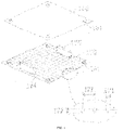
- Figure 1 is a schematic illustration of a first metal plate 160 and a second metal plate 170, each comprising perforations 161.
- the thermoplastic-facing surface of the second metal plate 170 includes grooves 174 and includes two rigid spacers 175 to control the minimum separation of first metal plate 160 and second metal plate 170.
- the Figure 1 inset is an enlarged cross-sectional view of a portion of second metal plate 170 and illustrates groove width 171, groove depth 172, and center-to-center groove separation 173.
- the flexible linkage comprises a metal wire, a metal band, poly( para -phenylene terephthalamide) fibers, carbon fibers, glass fibers, or a combination thereof. In some embodiments of the method, the flexible linkage comprises a metal wire, a metal band, or a combination thereof. In some embodiments, the flexible linkage comprises a metal wire or a metal band comprising galvanized iron, wherein the galvanized iron comprises 99.9 to 99.99 weight percent iron and 0.01 to 0.1 weight percent carbon, based on the weight of galvanized iron.
- Table 1 Material Description PPE 1 Poly(2,6-dimethyl-1,4-phenylene ether) having an intrinsic viscosity of about 0.46 deciliter/gram, measured at 23 °C in chloroform by Ubbelohde viscometer. PPE 2 Poly(2,6-dimethyl-1,4-phenylene ether) having an intrinsic viscosity of about 0.40 deciliter/gram, measured at 23 °C in chloroform by Ubbelohde viscometer. HIPS Rubber-modified polystyrene having a polystyrene content of about 89 weight percent.
- FR 1 Bisphenol A bis(diphenyl phosphate).
- FR 2 Aminoethylaminopropylpolysiloxane, CAS Reg. No. 67923-07-3 .
- Additives One or more additives selected from antioxidants, mold release agents, and colorants.
- Resin compositions are summarized in Table 2, where component amounts are expressed in weight percent based on the total weight of the composition.
- Compositions were compounded on a 36 millimeter twin-screw extruder operating at barrel temperatures of 200, 230, 260, 260, 280, 280, 280, 285, and 275 °C from feed throat to die, and a die temperature of 275 °C.
- Extrudates were cooled and pelletized, then dried for 3 hours at 100 °C before use for sheet extrusion. Glass transition temperatures, expressed in units of degrees centigrade, were determined by differential scanning calorimetry according to ASTM D3418-15 at heating rate of 20 °C/minute.
- Sheet extrusion of the resin compositions was conducted on a sheet extrusion apparatus operating at barrel temperatures of 200, 240, 260, 270, 280, 280, 260, 250 °C, and a die temperature of 245 °C. Sheet thicknesses are specified below in the context of individual experiments.
- This experiment utilized an extruded sheet of Resin A having a length of 300 millimeters, a width of 200 millimeters, and thickness of 5 millimeters. Also utilized were two aluminum plates with a length of 1000 millimeters, a width of 600 millimeters, and a thickness of 5 millimeters. The inner (thermoplastic-facing) surfaces of both aluminum plates were machined to create a grid of perpendicular micro grooves with a width of 0.5 millimeter, a depth of 0.5 millimeter, and a center-to-center groove separation of 2 millimeters.
- a dual-plate/soft-link module was created by perforating the four corners of the aluminum plates and connecting the aluminum plates to a soft link consisting of a metal wire hoop having a circular cross-section, a wire cross-sectional diameter of 1 millimeter and a hoop circumference of about 200 millimeters.
- the metal wire used to form the hoop was a galvanized iron wire containing 99.98 weight percent iron and 0.02 weight percent carbon.
- the connection of the aluminum plates to the wire hoop was accomplished by looping the wire of the wire hoop multiple times through each hole in the aluminum plates.
- the initial spacing between the two aluminum plates was about 25 millimeters, but the spacing could be reduced by compressing the dual-plate/soft-link module to create a minimum plate spacing equivalent to or slightly less than (e.g., as much as 5 percent less than) the thickness of the final foam sheet.
- the minimum plate spacing was controlled by two rigid spacers adhered to opposite edges of the thermoplastic-facing surface of the lower aluminum plate.
- the extruded sheet was placed between the two aluminum plates, which were separated by about 25 millimeters.
- the cavity of a foaming machine was pre-heated to 160 °C, then the dual-plate/soft-link module containing the extruded sheet was placed in foaming machine 1, and the mold cavity was closed by the hydraulic presses of the foaming machine. Closure of the mold cavity did not affect the plate separation of about 25 millimeters.
- supercritical carbon dioxide was injected into the cavity of the foaming machine, and a temperature of 160 °C and a pressure of 20 megapascals of carbon dioxide were maintained for 60 minutes.
- the dual-plate/soft-link module containing the foamed sheet was rapidly transferred to the shaping machine, which had an initial temperature of about 23 °C, and the hydraulic presses of the shaping machine rapidly closed, creating a plate spacing of 21 millimeters and a pressure of about 0.6 megapascals. After five minutes, the hydraulic presses increased the plate spacing to about 25 millimeters, and the foamed sheet was removed from the dual-plate/soft-link module.
- the resulting flat shaped foamed sheet had a thickness of 21 millimeters, and a density of 0.045 gram/centimeter 3 , determined according to ASTM D1622-14.
- the major surfaces of the sheet included projections corresponding to the grooves in the aluminum plates.
- the shaped foamed sheet did not exhibit cracks or surface wrinkles, and its thickness and density were uniform.
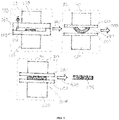
- FIG. 2 is a schematic illustration of the process for foaming and shaping a thermoplastic sheet according to the present invention and Example 1.
- the process utilizes a foaming machine 10 and a shaping machine.
- the shaping machine is shown in an uncompressed configuration 20 and a compressed configuration 30.
- Foaming machine 10 includes a foaming machine upper hydraulic press 110 and a foaming machine lower hydraulic press 120 which control vertical movement of foaming machine upper wall 140 and foaming machine lower wall 150, respectively.
- Embedded in foaming machine upper wall 140 is carbon dioxide inlet/outlet with valve 130.
- Pictured within the chamber of foaming machine 10 is a dual-plate/soft-link module, which includes first metal plate 160 and second metal plate 170, which are connected by flexible linkage 180.
- Unfoamed thermoplastic sheet 190 rests on second metal plate 170. After unfoamed thermoplastic sheet 190 is foamed with carbon dioxide to form foamed unshaped thermoplastic sheet 290 in foaming machine 10, carbon dioxide is vented via carbon dioxide inlet/outlet with valve 130 and the chamber is opened via foaming machine upper hydraulic press 110 and a foaming machine lower hydraulic press 120. The dual-plate/soft-link module is rapidly transferred from foaming machine 10 to shaping machine in uncompressed configuration 20. This transfer is represented by the arrow labeled 200.
- the shaping machine includes shaping machine upper hydraulic press 210, shaping machine lower hydraulic press 220, shaping machine upper hydraulic press contact plate 230, and shaping machine upper hydraulic press contact plate 240.
- Shaping machine upper hydraulic press 210 and shaping machine lower hydraulic press 220 are used to convert the shaping machine from its uncompressed configuration 20 to its compressed configuration 30, in which the minimum separation of first metal plate 160 and the second metal plate 170 is controlled by at least one rigid spacer 175 (not shown in Figure 2 but illustrated in Figure 1 ) on the thermoplastic-facing major surface of first metal plate 160 or second metal plate 170 or both. Conversion of the shaping machine from its uncompressed configuration to its compressed configuration is represented by the arrow labeled 300. In the compressed configuration 30 of the shaping machine, the foamed unshaped thermoplastic sheet is shaped and cooled to form shaped foamed sheet without defects 390.
- Shaping machine upper hydraulic press 210 and shaping machine lower hydraulic press 220 are then used to convert the shaping machine back to its uncompressed configuration 20, the dual-plate/soft-link module is removed from the shaping machine, and shaped foamed sheet without defects 390 is removed from the dual-plate/soft-link module. Removal of the shaped foamed sheet is represented by the arrow labeled 400.
- Example 1 The procedure of Example 1 was followed, except that the plate spacing during foaming was about 17 millimeters, foaming was conducted at 145 °C, and the plate spacing during shaping was about 10 millimeters.
- the resulting flat shaped foamed sheet had a thickness of about 10 millimeters, and a density of 0.14 gram/centimeter 3 , determined according to ASTM D1622-14.
- the surface of the sheet included projections corresponding to the grooves in the aluminum plates.
- the shaped foamed sheet did not exhibit cracks or surface wrinkles, and its thickness and density were uniform.
- Example 1 The procedure of Example 1 was followed, except that Resin B was used, foaming was conducted at 165 °C for 70 minutes, and the plate spacing during shaping was about 19 millimeters was.
- the resulting flat shaped foamed sheet had a thickness of about 19 millimeters, and a density of 0.065 gram/centimeter 3 , determined according to ASTM D1622-14.
- the surface of the sheet included projections corresponding to the grooves in the aluminum plates.
- the shaped foamed sheet did not exhibit cracks or surface wrinkles, and its thickness and density were uniform.
- Example 1 The procedure of Example 1 was followed, except that the thermoplastic sheet had a thickness of 3 millimeters, the plate spacing during foaming was about 12 millimeters, foaming was conducted at 145 °C for 50 minutes, and the plate spacing during shaping was about 7 millimeters.
- the resulting flat foamed and shaped sheet had a thickness of about 7 millimeters, and a density of 0.15 gram/centimeter 3 , determined according to ASTM D1622-14.
- the surface of the sheet included projections corresponding to the grooves in the aluminum plates.
- the shaped foamed sheet did not exhibit cracks or surface wrinkles, and its thickness and density were uniform.
- This experiment utilized an extruded sheet of Resin A having a length of 300 millimeters, a width of 200 millimeters, and thickness of 5 millimeters. Aluminum plates were not used in this experiment.
- the extruded sheet was placed on the lower surface of the hydraulic press of the cavity of the foaming machine, which had been pre-heated to 160 °C.
- the mold cavity of foaming machine was closed by the hydraulic system yielding a separation of about 50 millimeters between the upper and lower surfaces of the hydraulic press.
- supercritical carbon dioxide was injected into the cavity of the foaming machine, and a temperature of 160 °C and a pressure of 20 megapascals of carbon dioxide were maintained for 60 minutes.
- the foamed sheet had a warped (i.e., non-flat) shape.
- the foamed sheet was rapidly transferred to the shaping machine, which had an initial temperature of about 23 °C, and the hydraulic presses of the shaping machine rapidly closed, creating a separation of about 20 millimeters between the upper and lower surfaces of the hydraulic press, and a pressure of about 0.6 megapascals.
- the separation between the upper and lower surfaces of the hydraulic press was increased to about 200 millimeters, and the shaped foamed sheet was removed from the shaping machine.
- the resulting shaped foamed sheet had a thickness of about 20 millimeters, and a density of 0.045 gram/centimeter 3 , determined according to ASTM D1622-14, but it exhibited unacceptable cracking, and the surface of the foamed sheet exhibited unacceptable surface wrinkles.
- Figure 3 The process is schematically illustrated in Figure 3 , which is similar to Figure 2 except that a dual-plate/soft-link module was not employed, and the final product was shaped foamed sheet exhibiting cracking and surface wrinkling 394.
- This experiment utilized an extruded sheet of Resin A having a length of 300 millimeters, a width of 200 millimeters, and thickness of 5 millimeters. Also utilized were two aluminum plates with a length of 1000 millimeters, a width of 600 millimeters, and a thickness of 5 millimeters. The inner surfaces of both aluminum plates were machined to create a grid of perpendicular micro grooves with a width of 0.5 millimeter, a depth of 0.5 millimeter, and a center-to-center groove separation of 2 millimeters. The aluminum plates were connected with bolts to create a fixed separation of about 20 millimeters, thereby creating a dual-plate/fixed-separation module.
- the extruded sheet was placed between the two aluminum plates.
- the cavity of the foaming machine was heated to 160 °C, then the dual-plate/fixed-separation module containing the extruded sheet was placed in the foaming machine, and the mold cavity was closed. Then, supercritical carbon dioxide was injected into the cavity of the foaming machine, and a temperature of 160 °C and a pressure of 20 megapascals of carbon dioxide were maintained for 60 minutes.
- the resulting shaped foamed sheet had a thickness of about 20 millimeters, and a density of 0.045 gram/centimeter 3 , determined according to ASTM D1622-14, but the surface of the foamed sheet exhibited unacceptable surface wrinkles, and the thickness and density were not uniform across the sheet.
- Figure 4 The process is schematically illustrated in Figure 4 , which is similar to Figure 2 except that the dual-plate/soft-link module is replaced with a dual-plate/fixed-separation module in which rigid spacers 185 connect and create a fixed separation of first metal plate 160 and second metal plate 170, and the final product was shaped foamed sheet exhibiting surface wrinkling, and non-uniform thickness and density 396.
- This experiment utilized an extruded sheet of Resin A having a length of 300 millimeters, a width of 200 millimeters, and thickness of 5 millimeters. Also utilized were two aluminum plates with a length of 1000 millimeters, a width of 600 millimeters, and a thickness of 5 millimeters. Neither aluminum plate was grooved.
- a dual-plate/soft-link module was created by perforating the four corners of the aluminum plates and connecting the aluminum plates to a soft link consisting of a metal wire hoop having a circular cross-section, a wire cross-sectional diameter of 1 millimeter and a hoop circumference of about 200 millimeters.
- the initial spacing between the two aluminum plates was about 25 millimeters, but the spacing could be reduced by compressing the dual-plate/soft-link module to create a plate spacing equivalent to or slightly less than (e.g., as much as 5 percent less than) the thickness of the final foam sheet.
- the extruded sheet was placed between the two aluminum plates.
- the cavity of the foaming machine was heated to 160 °C, then the dual-plate/soft-link module containing the extruded sheet was placed in foaming machine, and the mold cavity was closed. Closure of the mold cavity did not affect the plate separation of about 25 millimeters.
- supercritical carbon dioxide was injected into the cavity of the foaming machine, and a temperature of 160 °C and a pressure of 20 megapascals of carbon dioxide were maintained for 60 minutes.
- the foamed sheet had a warped (i.e., non-flat) shape.
- the dual-plate/soft-link module containing the warped foamed sheet was rapidly transferred to the shaping machine, which had an initial temperature of about 23 °C.
- the hydraulic presses of the shaping machine rapidly closed, creating a plate spacing of about 7 millimeters, a pressure of about 0.6 megapascals.
- the shaped foamed sheet was removed from the dual-plate/soft-link module.
- the resulting shaped foamed sheet had a thickness of about 7 millimeters, and a density of 0.15 gram/centimeter 3 , but the thickness and density were not uniform across the sheet.
- Table 3 summarizes the conditions and results for the experiments described above.
- N/A means not applicable.
- Examples 1-4 were conducted according to the present method and utilized a dual-plate/soft-link module in which both plates had grooved surfaces facing the thermoplastic sheet. The resulting shaped foamed sheets exhibited uniform thickness and density and were free of cracks and surface wrinkles.
- Comparative Example 1 the dual-plate/soft-link module was not employed and during shaping, the foamed sheet was in direct contact with smooth surfaces of the hydraulic press. The resulting shaped foamed sheet exhibited cracking and surface wrinkling.
- Comparative Example 2 the grooved aluminum plates were maintained at a fixed separation of 20 millimeters during foaming and shaping, and the resulting shaped foamed sheet exhibited surface wrinkles and non-uniform thickness and density.
- Comparative Example 3 the aluminum plates lacked grooves, and the resulting shaped foamed sheet exhibited non-uniform thickness and density.
- the invention includes at least the following aspects.
Landscapes
- Engineering & Computer Science (AREA)
- Mechanical Engineering (AREA)
- Chemical & Material Sciences (AREA)
- Polymers & Plastics (AREA)
- Chemical Kinetics & Catalysis (AREA)
- Medicinal Chemistry (AREA)
- Health & Medical Sciences (AREA)
- Organic Chemistry (AREA)
- Materials Engineering (AREA)
- Manufacture Of Porous Articles, And Recovery And Treatment Of Waste Products (AREA)
- Moulds For Moulding Plastics Or The Like (AREA)
- Casting Or Compression Moulding Of Plastics Or The Like (AREA)
- Molding Of Porous Articles (AREA)
- Compositions Of Macromolecular Compounds (AREA)
Abstract
Description
- Foaming of thermoplastics with supercritical carbon dioxide is a cost-effective and residue-free method of forming foamed thermoplastic sheets. A combination of a foaming step and a subsequent shaping step is commercially practiced primarily for thermoplastics with glass transition temperatures less than 0 °C, including polypropylenes, thermoplastic polyurethanes, ethylene-vinyl acetate copolymers, and polyester elastomers. Typically, foaming is conducted in a high-temperature foaming machine, then the foamed sheet is transferred to a separate room temperature machine for cooling and shaping. The process works well for thermoplastics with glass transition tem less than 0 °C, because the foamed sheets are still soft when they are transferred to the room temperature cooling and shaping machine. However, application of this two-step process to thermoplastics with higher glass transition temperatures is problematic in that the foamed sheets are prone to cracking, surface deformation, and non-uniform foamed sheet thickness and density. There is therefore a need for an improved process of cooling and shaping foamed sheets prepared with supercritical carbon dioxide from thermoplastics having a glass transition temperature of at least 20 °C.
- One embodiment is a method of foaming and shaping a thermoplastic sheet, comprising: foaming a thermoplastic sheet with supercritical carbon dioxide to form a foamed thermoplastic sheet; wherein the thermoplastic sheet comprises a thermoplastic composition comprising a poly(phenylene ether), a polyetherimide, or a combination thereof; and wherein the thermoplastic composition is characterized by a glass transition temperature of 20 to 300 °C determined by differential scanning calorimetry according to ASTM D3418-15 at heating rate of 20 °C/minute; and shaping the foamed thermoplastic sheet to form a shaped foamed thermoplastic sheet; wherein the shaping comprises compressing the foamed thermoplastic sheet between a first metal plate and a second metal plate; wherein a surface of the first metal plate and a surface of the second metal plate comprise a plurality of grooves, each groove having a width of 0.1 to 1 millimeter and a depth of 0.1 to 1 millimeter, and each groove being separated from the nearest groove by a center-to-center distance of 0.5 to 5 millimeters; wherein the first metal plate and the second metal plate are connected by a flexible linkage capable of modulating a separation between the first metal plate and the second metal plate; and wherein the compressing the foamed thermoplastic sheet between a first metal plate and a second metal plate comprises controlling a minimum separation of the first metal plate and the second metal plate.
- Another embodiment is a shaped foamed thermoplastic sheet produced by the method in any of its variations described herein and comprising a plurality of projections corresponding to the plurality of grooves of the first metal plate and the second metal plate.
- Another embodiment is an electric vehicle battery comprising the shaped foamed thermoplastic sheet in any of its variations.
- Another embodiment is an apparatus for shaping a foamed thermoplastic sheet, comprising: a first metal plate and a second metal plate; wherein each of the first metal plate and the second metal plate comprises a thermoplastic-facing major surface; wherein the thermoplastic-facing major surface of the first metal plate or the second metal plate or both comprises a plurality of grooves, each groove having a width of 0.1 to 1 millimeter and a depth of 0.1 to 1 millimeter; and wherein the thermoplastic-facing major surface of the first metal plate or the second metal plate or both comprises a rigid spacer to control the minimum separation of the first metal plate and the second metal plate; a flexible linkage connecting the first metal plate and the second metal plate, the flexible linkage being capable of modulating a separation between the first metal plate and the second metal plate; and a hydraulic system capable of compressing the flexible linkage connecting the first metal plate and the second metal plate.
- These and other embodiments are described in detail below.
- In the drawings, like elements are numbered alike in several figures.
-
Figure 1 is a schematic illustration of afirst metal plate 160 and asecond metal plate 170; the inset is an enlarged cross-sectional view of a portion ofsecond metal plate 170. -
Figure 2 is a schematic illustration of a process for foaming and shaping a thermoplastic sheet according to the present invention. -
Figure 3 is a schematic illustration of a comparative process for foaming and shaping a thermoplastic sheet without using the present invention's first and second metal plates, or the flexible linkage connecting the first and second metal plates. -
Figure 4 is a schematic illustration of a comparative process for foaming and shaping a thermoplastic sheet without using the present invention's flexible linkage connecting the first and second metal plates. - The present inventors have determined that thermoplastics having a glass transition temperature of at least 20 °C can be foamed with supercritical carbon dioxide, then cooled and shaped without cracking, surface deformation, non-uniform foamed sheet thickness, or non-uniform foamed sheet density by a process including a cooling and shaping step that utilizes grooved metal plates connected by a flexible linkage.
- Thus, one embodiment is a method of foaming and shaping a thermoplastic sheet, comprising: foaming a thermoplastic sheet with supercritical carbon dioxide to form a foamed thermoplastic sheet; wherein the thermoplastic sheet comprises a thermoplastic composition comprising a poly(phenylene ether), a polyetherimide, or a combination thereof; and wherein the thermoplastic composition is characterized by a glass transition temperature of 20 to 300 °C determined by differential scanning calorimetry according to ASTM D3418-15 at heating rate of 20 °C/minute; and shaping the foamed thermoplastic sheet to form a shaped foamed thermoplastic sheet; wherein the shaping comprises compressing the foamed thermoplastic sheet between a first metal plate and a second metal plate; wherein a surface of the first metal plate and a surface of the second metal plate comprise a plurality of grooves, each groove having a width of 0.1 to 1 millimeter and a depth of 0.1 to 1 millimeter, and each groove being separated from the nearest groove by a center-to-center distance of 0.5 to 5 millimeters; wherein the first metal plate and the second metal plate are connected by a flexible linkage capable of modulating a separation between the first metal plate and the second metal plate; and wherein the compressing the foamed thermoplastic sheet between a first metal plate and a second metal plate comprises controlling a minimum separation of the first metal plate and the second metal plate.
- The first metal plate, the second metal plate, and the flexible linkage collectively form a dual-plate/soft-link module. The flexible linkage allows the dual-plate/soft-link module to be compressible, thereby modulating the separation between the first metal plate and the second metal plate. When the dual-plate/soft-link module is uncompressed, the separation between the first metal plate and the second metal plate is such that the first (upper) metal plate is not in contact with shaped foamed thermoplastic sheet. When the dual-plate/soft-link module is compressed, the separation between the first metal plate and the second metal plate is such that the first (upper) metal plate and the second (lower) metal plate are both in contact with the shaped foamed thermoplastic sheet. The minimum separation between the first and second metal plates is controlled by one or more rigid spacers attached to the thermoplastic-facing surfaces of first metal plate, the second metal plate, or both.
- In some embodiments of the method, the flexible linkage comprises a metal wire, a metal band, poly(para-phenylene terephthalamide) fibers, carbon fibers, glass fibers, or a combination thereof. In some embodiments of the method, the flexible linkage comprises a metal wire, a metal band, or a combination thereof. In some embodiments, the flexible linkage comprises a metal wire or a metal band comprising galvanized iron comprising 99.9 to 99.99 weight percent iron and 0.01 to 0.1 weight percent carbon, based on the weight of galvanized iron.
- The thermoplastic-facing major surfaces of the first metal plate and the second metal plate comprise a plurality of grooves, each groove having a width of 0.1 to 1 millimeter and a depth of 0.1 to 1 millimeter, and each groove being separated from the nearest groove by a center-to-center distance of 0.5 to 5 millimeters. Within these ranges, the width can be 0.2 to 1 millimeter, the depth can be 0.2 to 1 millimeter, and the center-to-center groove separation can be 1 to 5 millimeters. In some embodiments, the metal plate surfaces comprise a plurality of parallel grooves. In some embodiments, the metal plate surfaces comprise a first set of parallel grooves and a second set of parallel grooves, wherein the grooves of the first set are perpendicular to the grooves of the second set.
- In some embodiments, foaming a thermoplastic sheet with supercritical carbon dioxide to form a foamed thermoplastic sheet comprises venting the carbon dioxide from the foaming machine in 10 seconds or less, or 5 seconds or less, or 3 seconds or less.
- The thermoplastic composition is characterized by a glass transition temperature of 20 to 300 °C determined by differential scanning calorimetry according to ASTM D3418-15 at heating rate of 20 °C/minute. Within this range, the glass transition temperature can be 50 to 300 °C, or 100 to 300 °C, or 120 to 300 °C.
- In some embodiments of the method, the thermoplastic composition comprises a poly(phenylene ether). For example, the thermoplastic composition can comprise, based on the total weight of the thermoplastic composition, 40 to 78 weight percent of the poly(phenylene ether); 10 to 48 weight percent of polystyrene, a rubber-modified polystyrene, or a combination thereof; 2 to 10 weight percent of a block copolymer comprising a polystyrene block and a polybutadiene block, a block copolymer comprising a polystyrene block and a hydrogenated polybutadiene block, or a combination thereof; and 10 to 20 weight percent of a flame retardant; wherein the sum of the weight percents of the poly(phenylene ether), the polystyrene or rubber-modified polystyrene or combination thereof, the block copolymer, and the flame retardant is 95 to 100 weight percent. As another example, the thermoplastic composition can comprise, based on the total weight of the thermoplastic composition, 50 to 78 weight percent of the poly(phenylene ether); 10 to 38 weight percent of polystyrene, a rubber-modified polystyrene, or a combination thereof; 2 to 10 weight percent of a block copolymer comprising a polystyrene block and a polybutadiene block, a block copolymer comprising a polystyrene block and a hydrogenated polybutadiene block, or a combination thereof; and 10 to 20 weight percent of a flame retardant; wherein the sum of the weight percents of the poly(phenylene ether), the polystyrene or rubber-modified polystyrene or combination thereof, the block copolymer, and the flame retardant is 95 to 100 weight percent.
- In some embodiments of the method, the thermoplastic composition comprises a polyetherimide.
- Another embodiment is a shaped foamed thermoplastic sheet produced by any of the above-described embodiments of the method, and comprising a plurality of projections on its two major faces, the plurality of projections corresponding to the plurality of grooves of the first metal plate and the second metal plate.
- Another embodiment is a shaped foamed thermoplastic sheet produced by any of the above-described variations of the method, and comprising a poly(phenylene ether). For example, the thermoplastic composition can comprise, based on the total weight of the thermoplastic composition, 40 to 78 weight percent of the poly(phenylene ether); 10 to 48 weight percent of polystyrene, a rubber-modified polystyrene, or a combination thereof; 2 to 10 weight percent of a block copolymer comprising a polystyrene block and a polybutadiene block, a block copolymer comprising a polystyrene block and a hydrogenated polybutadiene block, or a combination thereof; and 10 to 20 weight percent of a flame retardant; wherein the sum of the weight percents of the poly(phenylene ether), the polystyrene or rubber-modified polystyrene or combination thereof, the block copolymer, and the flame retardant is 95 to 100 weight percent. As another example, the thermoplastic composition can comprise, based on the total weight of the thermoplastic composition, 50 to 78 weight percent of the poly(phenylene ether); 10 to 38 weight percent of polystyrene, a rubber-modified polystyrene, or a combination thereof; 2 to 10 weight percent of a block copolymer comprising a polystyrene block and a polybutadiene block, a block copolymer comprising a polystyrene block and a hydrogenated polybutadiene block, or a combination thereof; and 10 to 20 weight percent of a flame retardant; wherein the sum of the weight percents of the poly(phenylene ether), the polystyrene or rubber-modified polystyrene or combination thereof, the block copolymer, and the flame retardant is 95 to 100 weight percent.
- Another embodiment is a shaped foamed thermoplastic sheet produced by any of the above-described variations of the method, and comprising a polyetherimide.
- Another embodiment is an electric vehicle battery comprising the shaped foamed thermoplastic sheet in any of its above-described variations.
- Another embodiment is an apparatus for shaping a foamed thermoplastic sheet, comprising: a first metal plate and a second metal plate; wherein each of the first metal plate and the second metal plate comprises a thermoplastic-facing major surface; wherein the thermoplastic-facing major surfaces of the first metal plate and the second metal plate comprise a plurality of grooves, each groove having a width of 0.1 to 1 millimeter and a depth of 0.1 to 1 millimeter, and each groove being separated from the nearest groove by a center-to-center distance of 0.5 to 5 millimeters; and wherein the thermoplastic-facing major surface of the first metal plate or the second metal plate or both comprises a rigid spacer to control the minimum separation of the first metal plate and the second metal plate; a flexible linkage connecting the first metal plate and the second metal plate, the flexible linkage being capable of modulating a separation between the first metal plate and the second metal plate; and a hydraulic system capable of compressing the flexible linkage connecting the first metal plate and the second metal plate.
Figure 1 is a schematic illustration of afirst metal plate 160 and asecond metal plate 170, each comprisingperforations 161. The thermoplastic-facing surface of thesecond metal plate 170 includesgrooves 174 and includes tworigid spacers 175 to control the minimum separation offirst metal plate 160 andsecond metal plate 170. TheFigure 1 inset is an enlarged cross-sectional view of a portion ofsecond metal plate 170 and illustratesgroove width 171,groove depth 172, and center-to-center groove separation 173. - In some embodiments of the apparatus, the flexible linkage comprises a metal wire, a metal band, poly(para-phenylene terephthalamide) fibers, carbon fibers, glass fibers, or a combination thereof. In some embodiments of the method, the flexible linkage comprises a metal wire, a metal band, or a combination thereof. In some embodiments, the flexible linkage comprises a metal wire or a metal band comprising galvanized iron, wherein the galvanized iron comprises 99.9 to 99.99 weight percent iron and 0.01 to 0.1 weight percent carbon, based on the weight of galvanized iron.
- All ranges disclosed herein are inclusive of the endpoints, and the endpoints are independently combinable with each other. Each range disclosed herein constitutes a disclosure of any point or sub-range lying within the disclosed range.
- The invention is further illustrated by the following non-limiting examples.
- Components used in these experiments are summarized in Table 1.
Table 1 Material Description PPE 1 Poly(2,6-dimethyl-1,4-phenylene ether) having an intrinsic viscosity of about 0.46 deciliter/gram, measured at 23 °C in chloroform by Ubbelohde viscometer. PPE 2 Poly(2,6-dimethyl-1,4-phenylene ether) having an intrinsic viscosity of about 0.40 deciliter/gram, measured at 23 °C in chloroform by Ubbelohde viscometer. HIPS Rubber-modified polystyrene having a polystyrene content of about 89 weight percent. SBS Poly(styrene-butadiene-styrene) triblock copolymer having a polystyrene content of about 69 weight percent. FR 1 Bisphenol A bis(diphenyl phosphate). FR 2 Aminoethylaminopropylpolysiloxane, CAS Reg. No. 67923-07-3. Additives One or more additives selected from antioxidants, mold release agents, and colorants. - Resin compositions are summarized in Table 2, where component amounts are expressed in weight percent based on the total weight of the composition. Compositions were compounded on a 36 millimeter twin-screw extruder operating at barrel temperatures of 200, 230, 260, 260, 280, 280, 280, 285, and 275 °C from feed throat to die, and a die temperature of 275 °C. Extrudates were cooled and pelletized, then dried for 3 hours at 100 °C before use for sheet extrusion. Glass transition temperatures, expressed in units of degrees centigrade, were determined by differential scanning calorimetry according to ASTM D3418-15 at heating rate of 20 °C/minute.
Table 2 Resin A Resin B COMPOSITION PPE 1 50.0 0 PPE 2 0 70.0 HIPS 30.0 10.0 SBS 2.5 5.0 FR 116.5 10.0 FR 2 0 3.5 Additives 1.0 1.5 PROPERTIES Glass transition temperature (°C) 125 160 - Sheet extrusion of the resin compositions was conducted on a sheet extrusion apparatus operating at barrel temperatures of 200, 240, 260, 270, 280, 280, 260, 250 °C, and a die temperature of 245 °C. Sheet thicknesses are specified below in the context of individual experiments.
- This experiment utilized an extruded sheet of Resin A having a length of 300 millimeters, a width of 200 millimeters, and thickness of 5 millimeters. Also utilized were two aluminum plates with a length of 1000 millimeters, a width of 600 millimeters, and a thickness of 5 millimeters. The inner (thermoplastic-facing) surfaces of both aluminum plates were machined to create a grid of perpendicular micro grooves with a width of 0.5 millimeter, a depth of 0.5 millimeter, and a center-to-center groove separation of 2 millimeters. A dual-plate/soft-link module was created by perforating the four corners of the aluminum plates and connecting the aluminum plates to a soft link consisting of a metal wire hoop having a circular cross-section, a wire cross-sectional diameter of 1 millimeter and a hoop circumference of about 200 millimeters. The metal wire used to form the hoop was a galvanized iron wire containing 99.98 weight percent iron and 0.02 weight percent carbon. The connection of the aluminum plates to the wire hoop was accomplished by looping the wire of the wire hoop multiple times through each hole in the aluminum plates. In the dual-plate/soft-link module, the initial spacing between the two aluminum plates was about 25 millimeters, but the spacing could be reduced by compressing the dual-plate/soft-link module to create a minimum plate spacing equivalent to or slightly less than (e.g., as much as 5 percent less than) the thickness of the final foam sheet. The minimum plate spacing was controlled by two rigid spacers adhered to opposite edges of the thermoplastic-facing surface of the lower aluminum plate.
- The extruded sheet was placed between the two aluminum plates, which were separated by about 25 millimeters. The cavity of a foaming machine was pre-heated to 160 °C, then the dual-plate/soft-link module containing the extruded sheet was placed in foaming
machine 1, and the mold cavity was closed by the hydraulic presses of the foaming machine. Closure of the mold cavity did not affect the plate separation of about 25 millimeters. Then, supercritical carbon dioxide was injected into the cavity of the foaming machine, and a temperature of 160 °C and a pressure of 20 megapascals of carbon dioxide were maintained for 60 minutes. - After the 60 minutes had elapsed, pressure was released through an exhaust port in about 2 seconds, and the cavity was opened. At this point, the foamed sheet had a warped (i.e., non-flat) shape. The dual-plate/soft-link module containing the foamed sheet was rapidly transferred to the shaping machine, which had an initial temperature of about 23 °C, and the hydraulic presses of the shaping machine rapidly closed, creating a plate spacing of 21 millimeters and a pressure of about 0.6 megapascals. After five minutes, the hydraulic presses increased the plate spacing to about 25 millimeters, and the foamed sheet was removed from the dual-plate/soft-link module. The resulting flat shaped foamed sheet had a thickness of 21 millimeters, and a density of 0.045 gram/centimeter3, determined according to ASTM D1622-14. The major surfaces of the sheet included projections corresponding to the grooves in the aluminum plates. The shaped foamed sheet did not exhibit cracks or surface wrinkles, and its thickness and density were uniform.
-
Figure 2 is a schematic illustration of the process for foaming and shaping a thermoplastic sheet according to the present invention and Example 1. The process utilizes a foamingmachine 10 and a shaping machine. InFigure 2 , the shaping machine is shown in anuncompressed configuration 20 and acompressed configuration 30. Foamingmachine 10 includes a foaming machine upperhydraulic press 110 and a foaming machine lowerhydraulic press 120 which control vertical movement of foaming machineupper wall 140 and foaming machinelower wall 150, respectively. Embedded in foaming machineupper wall 140 is carbon dioxide inlet/outlet withvalve 130. Pictured within the chamber of foamingmachine 10 is a dual-plate/soft-link module, which includesfirst metal plate 160 andsecond metal plate 170, which are connected byflexible linkage 180. Unfoamedthermoplastic sheet 190 rests onsecond metal plate 170. After unfoamedthermoplastic sheet 190 is foamed with carbon dioxide to form foamedunshaped thermoplastic sheet 290 in foamingmachine 10, carbon dioxide is vented via carbon dioxide inlet/outlet withvalve 130 and the chamber is opened via foaming machine upperhydraulic press 110 and a foaming machine lowerhydraulic press 120. The dual-plate/soft-link module is rapidly transferred from foamingmachine 10 to shaping machine inuncompressed configuration 20. This transfer is represented by the arrow labeled 200. The shaping machine includes shaping machine upperhydraulic press 210, shaping machine lowerhydraulic press 220, shaping machine upper hydraulicpress contact plate 230, and shaping machine upper hydraulicpress contact plate 240. Shaping machine upperhydraulic press 210 and shaping machine lowerhydraulic press 220 are used to convert the shaping machine from itsuncompressed configuration 20 to itscompressed configuration 30, in which the minimum separation offirst metal plate 160 and thesecond metal plate 170 is controlled by at least one rigid spacer 175 (not shown inFigure 2 but illustrated inFigure 1 ) on the thermoplastic-facing major surface offirst metal plate 160 orsecond metal plate 170 or both. Conversion of the shaping machine from its uncompressed configuration to its compressed configuration is represented by the arrow labeled 300. In thecompressed configuration 30 of the shaping machine, the foamed unshaped thermoplastic sheet is shaped and cooled to form shaped foamed sheet withoutdefects 390. Shaping machine upperhydraulic press 210 and shaping machine lowerhydraulic press 220 are then used to convert the shaping machine back to itsuncompressed configuration 20, the dual-plate/soft-link module is removed from the shaping machine, and shaped foamed sheet withoutdefects 390 is removed from the dual-plate/soft-link module. Removal of the shaped foamed sheet is represented by the arrow labeled 400. - The procedure of Example 1 was followed, except that the plate spacing during foaming was about 17 millimeters, foaming was conducted at 145 °C, and the plate spacing during shaping was about 10 millimeters. The resulting flat shaped foamed sheet had a thickness of about 10 millimeters, and a density of 0.14 gram/centimeter3, determined according to ASTM D1622-14. The surface of the sheet included projections corresponding to the grooves in the aluminum plates. The shaped foamed sheet did not exhibit cracks or surface wrinkles, and its thickness and density were uniform.
- The procedure of Example 1 was followed, except that Resin B was used, foaming was conducted at 165 °C for 70 minutes, and the plate spacing during shaping was about 19 millimeters was. The resulting flat shaped foamed sheet had a thickness of about 19 millimeters, and a density of 0.065 gram/centimeter3, determined according to ASTM D1622-14. The surface of the sheet included projections corresponding to the grooves in the aluminum plates. The shaped foamed sheet did not exhibit cracks or surface wrinkles, and its thickness and density were uniform.
- The procedure of Example 1 was followed, except that the thermoplastic sheet had a thickness of 3 millimeters, the plate spacing during foaming was about 12 millimeters, foaming was conducted at 145 °C for 50 minutes, and the plate spacing during shaping was about 7 millimeters. The resulting flat foamed and shaped sheet had a thickness of about 7 millimeters, and a density of 0.15 gram/centimeter3, determined according to ASTM D1622-14. The surface of the sheet included projections corresponding to the grooves in the aluminum plates. The shaped foamed sheet did not exhibit cracks or surface wrinkles, and its thickness and density were uniform.
- This experiment utilized an extruded sheet of Resin A having a length of 300 millimeters, a width of 200 millimeters, and thickness of 5 millimeters. Aluminum plates were not used in this experiment.
- The extruded sheet was placed on the lower surface of the hydraulic press of the cavity of the foaming machine, which had been pre-heated to 160 °C. The mold cavity of foaming machine was closed by the hydraulic system yielding a separation of about 50 millimeters between the upper and lower surfaces of the hydraulic press. Then, supercritical carbon dioxide was injected into the cavity of the foaming machine, and a temperature of 160 °C and a pressure of 20 megapascals of carbon dioxide were maintained for 60 minutes.
- After the 60 minutes had elapsed, pressure was released through an exhaust port, and the cavity was opened. At this point, the foamed sheet had a warped (i.e., non-flat) shape. The foamed sheet was rapidly transferred to the shaping machine, which had an initial temperature of about 23 °C, and the hydraulic presses of the shaping machine rapidly closed, creating a separation of about 20 millimeters between the upper and lower surfaces of the hydraulic press, and a pressure of about 0.6 megapascals. After five minutes, the separation between the upper and lower surfaces of the hydraulic press was increased to about 200 millimeters, and the shaped foamed sheet was removed from the shaping machine. The resulting shaped foamed sheet had a thickness of about 20 millimeters, and a density of 0.045 gram/centimeter3, determined according to ASTM D1622-14, but it exhibited unacceptable cracking, and the surface of the foamed sheet exhibited unacceptable surface wrinkles.
- The process is schematically illustrated in
Figure 3 , which is similar toFigure 2 except that a dual-plate/soft-link module was not employed, and the final product was shaped foamed sheet exhibiting cracking andsurface wrinkling 394. - This experiment utilized an extruded sheet of Resin A having a length of 300 millimeters, a width of 200 millimeters, and thickness of 5 millimeters. Also utilized were two aluminum plates with a length of 1000 millimeters, a width of 600 millimeters, and a thickness of 5 millimeters. The inner surfaces of both aluminum plates were machined to create a grid of perpendicular micro grooves with a width of 0.5 millimeter, a depth of 0.5 millimeter, and a center-to-center groove separation of 2 millimeters. The aluminum plates were connected with bolts to create a fixed separation of about 20 millimeters, thereby creating a dual-plate/fixed-separation module.
- The extruded sheet was placed between the two aluminum plates. The cavity of the foaming machine was heated to 160 °C, then the dual-plate/fixed-separation module containing the extruded sheet was placed in the foaming machine, and the mold cavity was closed. Then, supercritical carbon dioxide was injected into the cavity of the foaming machine, and a temperature of 160 °C and a pressure of 20 megapascals of carbon dioxide were maintained for 60 minutes.
- After the 60 minutes had elapsed, pressure was released through an exhaust port, and the cavity was opened. At this point, the foamed sheet had a warped (i.e., non-flat) shape. The dual-plate/fixed-separation module containing the foamed sheet was rapidly transferred to the shaping machine, which had an initial temperature of about 23 °C. The plate separation was still fixed at about 20 millimeters. After five minutes, the foamed sheet was removed from the dual-plate/fixed-separation module. The process is schematically illustrated in
Figure 3 . The resulting shaped foamed sheet had a thickness of about 20 millimeters, and a density of 0.045 gram/centimeter3, determined according to ASTM D1622-14, but the surface of the foamed sheet exhibited unacceptable surface wrinkles, and the thickness and density were not uniform across the sheet. - The process is schematically illustrated in
Figure 4 , which is similar toFigure 2 except that the dual-plate/soft-link module is replaced with a dual-plate/fixed-separation module in whichrigid spacers 185 connect and create a fixed separation offirst metal plate 160 andsecond metal plate 170, and the final product was shaped foamed sheet exhibiting surface wrinkling, and non-uniform thickness anddensity 396. - This experiment utilized an extruded sheet of Resin A having a length of 300 millimeters, a width of 200 millimeters, and thickness of 5 millimeters. Also utilized were two aluminum plates with a length of 1000 millimeters, a width of 600 millimeters, and a thickness of 5 millimeters. Neither aluminum plate was grooved. A dual-plate/soft-link module was created by perforating the four corners of the aluminum plates and connecting the aluminum plates to a soft link consisting of a metal wire hoop having a circular cross-section, a wire cross-sectional diameter of 1 millimeter and a hoop circumference of about 200 millimeters. The initial spacing between the two aluminum plates was about 25 millimeters, but the spacing could be reduced by compressing the dual-plate/soft-link module to create a plate spacing equivalent to or slightly less than (e.g., as much as 5 percent less than) the thickness of the final foam sheet.
- The extruded sheet was placed between the two aluminum plates. The cavity of the foaming machine was heated to 160 °C, then the dual-plate/soft-link module containing the extruded sheet was placed in foaming machine, and the mold cavity was closed. Closure of the mold cavity did not affect the plate separation of about 25 millimeters. Then, supercritical carbon dioxide was injected into the cavity of the foaming machine, and a temperature of 160 °C and a pressure of 20 megapascals of carbon dioxide were maintained for 60 minutes.
- After the 60 minutes had elapsed, pressure was released through an exhaust port, and the cavity was opened. At this point, the foamed sheet had a warped (i.e., non-flat) shape. The dual-plate/soft-link module containing the warped foamed sheet was rapidly transferred to the shaping machine, which had an initial temperature of about 23 °C. The hydraulic presses of the shaping machine rapidly closed, creating a plate spacing of about 7 millimeters, a pressure of about 0.6 megapascals. After five minutes, the shaped foamed sheet was removed from the dual-plate/soft-link module. The resulting shaped foamed sheet had a thickness of about 7 millimeters, and a density of 0.15 gram/centimeter3, but the thickness and density were not uniform across the sheet.
- The process was similar to that schematically illustrated in
Figure 2 , except that neither thefirst metal plate 160 nor thesecond metal plate 170 was grooved. - Table 3 summarizes the conditions and results for the experiments described above. In Table 3, "N/A" means not applicable. Examples 1-4 were conducted according to the present method and utilized a dual-plate/soft-link module in which both plates had grooved surfaces facing the thermoplastic sheet. The resulting shaped foamed sheets exhibited uniform thickness and density and were free of cracks and surface wrinkles. In Comparative Example 1, the dual-plate/soft-link module was not employed and during shaping, the foamed sheet was in direct contact with smooth surfaces of the hydraulic press. The resulting shaped foamed sheet exhibited cracking and surface wrinkling. In Comparative Example 2, the grooved aluminum plates were maintained at a fixed separation of 20 millimeters during foaming and shaping, and the resulting shaped foamed sheet exhibited surface wrinkles and non-uniform thickness and density. In Comparative Example 3, the aluminum plates lacked grooves, and the resulting shaped foamed sheet exhibited non-uniform thickness and density.
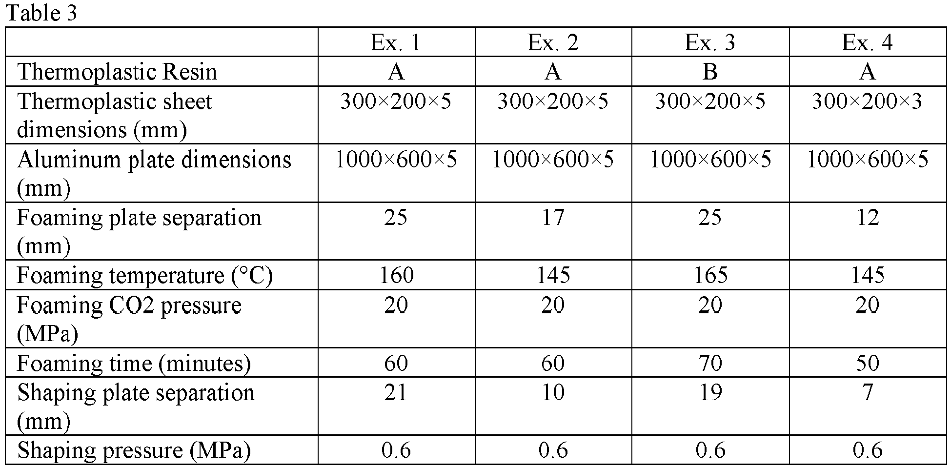

- The invention includes at least the following aspects.
- Aspect 1: A method of foaming and shaping a thermoplastic sheet, comprising: foaming a thermoplastic sheet with supercritical carbon dioxide to form a foamed thermoplastic sheet; wherein the thermoplastic sheet comprises a thermoplastic composition comprising a poly(phenylene ether), a polyetherimide, or a combination thereof; and wherein the thermoplastic composition is characterized by a glass transition temperature of 20 to 300 °C determined by differential scanning calorimetry according to ASTM D3418-15 at heating rate of 20 °C/minute; and shaping the foamed thermoplastic sheet to form a shaped foamed thermoplastic sheet; wherein the shaping comprises compressing the foamed thermoplastic sheet between a first metal plate and a second metal plate; wherein a surface of the first metal plate and a surface of the second metal plate comprise a plurality of grooves, each groove having a width of 0.1 to 1 millimeter and a depth of 0.1 to 1 millimeter, and each groove being separated from the nearest groove by a center-to-center distance of 0.5 to 5 millimeters; wherein the first metal plate and the second metal plate are connected by a flexible linkage capable of modulating a separation between the first metal plate and the second metal plate; and wherein the compressing the foamed thermoplastic sheet between a first metal plate and a second metal plate comprises controlling a minimum separation of the first metal plate and the second metal plate.
- Aspect 2: The method of
aspect 1, wherein the flexible linkage comprises a metal wire, a metal band, poly(para-phenylene terephthalamide) fibers, carbon fibers, glass fibers, or a combination thereof. - Aspect 3: The method of
aspect 1 or 2, wherein the flexible linkage comprises a metal wire or a metal band comprising galvanized iron, wherein the galvanized iron comprises 99.9 to 99.99 weight percent iron and 0.01 to 0.1 weight percent carbon, based on the weight of galvanized iron. - Aspect 4: The method of any one of aspects 1-3, wherein the thermoplastic composition comprises a poly(phenylene ether).
- Aspect 5: The method of aspect 4, wherein the thermoplastic composition has a glass transition temperature of 100 to 300 °C and comprises, based on the total weight of the thermoplastic composition, 40 to 78 weight percent of the poly(phenylene ether); 10 to 48 weight percent of polystyrene, a rubber-modified polystyrene, or a combination thereof; 2 to 10 weight percent of a block copolymer comprising a polystyrene block and a polybutadiene block, a block copolymer comprising a polystyrene block and a hydrogenated polybutadiene block, or a combination thereof; and 10 to 20 weight percent of a flame retardant; wherein the sum of the weight percents of the poly(phenylene ether), the polystyrene or rubber-modified polystyrene or combination thereof, the block copolymer, and the flame retardant is 95 to 100 weight percent.
- Aspect 6: The method of aspect 4, wherein the thermoplastic composition has a glass transition temperature of 100 to 300 °C and comprises, based on the total weight of the thermoplastic composition, 50 to 78 weight percent of the poly(phenylene ether); 10 to 38 weight percent of polystyrene, a rubber-modified polystyrene, or a combination thereof; 2 to 10 weight percent of a block copolymer comprising a polystyrene block and a polybutadiene block, a block copolymer comprising a polystyrene block and a hydrogenated polybutadiene block, or a combination thereof; and 10 to 20 weight percent of a flame retardant; wherein the sum of the weight percents of the poly(phenylene ether), the polystyrene or rubber-modified polystyrene or combination thereof, the block copolymer, and the flame retardant is 95 to 100 weight percent.
- Aspect 7: The method of any one of aspects 1-3, wherein the thermoplastic composition comprises a polyetherimide.
- Aspect 8: A shaped foamed thermoplastic sheet produced by the method of any one of aspects 1-7 and comprising a plurality of projections corresponding to the plurality of grooves of the first metal plate and the second metal plate.
- Aspect 9: The shaped foamed thermoplastic sheet of aspect 8, wherein the thermoplastic composition comprises a poly(phenylene ether).
- Aspect 10: The shaped foamed thermoplastic sheet of aspect 9, wherein the thermoplastic composition has a glass transition temperature of 100 to 300 °C and comprises, based on the total weight of the thermoplastic composition, 40 to 78 weight percent of the poly(phenylene ether); 10 to 48 weight percent of polystyrene, a rubber-modified polystyrene, or a combination thereof; 2 to 10 weight percent of a block copolymer comprising a polystyrene block and a polybutadiene block, a block copolymer comprising a polystyrene block and a hydrogenated polybutadiene block, or a combination thereof; and 10 to 20 weight percent of a flame retardant; wherein the sum of the weight percents of the poly(phenylene ether), the polystyrene or rubber-modified polystyrene or combination thereof, the block copolymer, and the flame retardant is 95 to 100 weight percent.
- Aspect 11: The shaped foamed thermoplastic sheet of aspect 9, wherein the thermoplastic composition has a glass transition temperature of 100 to 300 °C and comprises, based on the total weight of the thermoplastic composition, 50 to 78 weight percent of the poly(phenylene ether); 10 to 38 weight percent of polystyrene, a rubber-modified polystyrene, or a combination thereof; 2 to 10 weight percent of a block copolymer comprising a polystyrene block and a polybutadiene block, a block copolymer comprising a polystyrene block and a hydrogenated polybutadiene block, or a combination thereof; and 10 to 20 weight percent of a flame retardant; wherein the sum of the weight percents of the poly(phenylene ether), the polystyrene or rubber-modified polystyrene or combination thereof, the block copolymer, and the flame retardant is 95 to 100 weight percent.
- Aspect 12: The shaped foamed thermoplastic sheet of aspect 8, wherein the thermoplastic composition comprises a polyetherimide.
- Aspect 13: An electric vehicle battery comprising the shaped foamed thermoplastic sheet of any one of aspects 8-12.
- Aspect 14: An apparatus for shaping a foamed thermoplastic sheet, comprising: a first metal plate and a second metal plate; wherein each of the first metal plate and the second metal plate comprises a thermoplastic-facing major surface; wherein the thermoplastic-facing major surfaces of the first metal plate and the second metal plate comprise a plurality of grooves, each groove having a width of 0.1 to 1 millimeter and a depth of 0.1 to 1 millimeter, and each groove being separated from the nearest groove by a center-to-center distance of 0.5 to 5 millimeters; and wherein the thermoplastic-facing major surface of the first metal plate or the second metal plate or both comprises a rigid spacer to control the minimum separation of the first metal plate and the second metal plate; a flexible linkage connecting the first metal plate and the second metal plate, the flexible linkage being capable of modulating a separation between the first metal plate and the second metal plate; and a hydraulic system capable of compressing the flexible linkage connecting the first metal plate and the second metal plate.
- Aspect 15: The apparatus of aspect 14, wherein the flexible linkage comprises a metal wire, a metal band, poly(para-phenylene terephthalamide) fibers, carbon fibers, glass fibers, or a combination thereof.
Claims (15)
- A method of foaming and shaping a thermoplastic sheet, comprising:foaming a thermoplastic sheet with supercritical carbon dioxide to form a foamed thermoplastic sheet; wherein the thermoplastic sheet comprises a thermoplastic composition comprising a poly(phenylene ether), a polyetherimide, or a combination thereof; and wherein the thermoplastic composition is characterized by a glass transition temperature of 20 to 300 °C determined by differential scanning calorimetry according to ASTM D3418-15 at heating rate of 20 °C/minute; andshaping the foamed thermoplastic sheet to form a shaped foamed thermoplastic sheet; wherein the shaping comprises compressing the foamed thermoplastic sheet between a first metal plate and a second metal plate; wherein a surface of the first metal plate and a surface of the second metal plate comprise a plurality of grooves, each groove having a width of 0.1 to 1 millimeter and a depth of 0.1 to 1 millimeter, and each groove being separated from the nearest groove by a center-to-center distance of 0.5 to 5 millimeters; wherein the first metal plate and the second metal plate are connected by a flexible linkage capable of modulating a separation between the first metal plate and the second metal plate; and wherein the compressing the foamed thermoplastic sheet between a first metal plate and a second metal plate comprises controlling a minimum separation of the first metal plate and the second metal plate.
- The method of claim 1, wherein the flexible linkage comprises a metal wire, a metal band, poly(para-phenylene terephthalamide) fibers, carbon fibers, glass fibers, or a combination thereof.
- The method of claim 1 or 2, wherein the flexible linkage comprises a metal wire or a metal band comprising galvanized iron, wherein the galvanized iron comprises 99.9 to 99.99 weight percent iron and 0.01 to 0.1 weight percent carbon, based on the weight of galvanized iron.
- The method of any one of claims 1-3, wherein the thermoplastic composition comprises a poly(phenylene ether).
- The method of claim 4, wherein the thermoplastic composition has a glass transition temperature of 100 to 300 °C and comprises, based on the total weight of the thermoplastic composition, 40 to 78 weight percent of the poly(phenylene ether); 10 to 48 weight percent of polystyrene, a rubber-modified polystyrene, or a combination thereof; 2 to 10 weight percent of a block copolymer comprising a polystyrene block and a polybutadiene block, a block copolymer comprising a polystyrene block and a hydrogenated polybutadiene block, or a combination thereof; and 10 to 20 weight percent of a flame retardant; wherein the sum of the weight percents of the poly(phenylene ether), the polystyrene or rubber-modified polystyrene or combination thereof, the block copolymer, and the flame retardant is 95 to 100 weight percent.
- The method of claim 4, wherein the thermoplastic composition has a glass transition temperature of 100 to 300 °C and comprises, based on the total weight of the thermoplastic composition, 50 to 78 weight percent of the poly(phenylene ether); 10 to 38 weight percent of polystyrene, a rubber-modified polystyrene, or a combination thereof; 2 to 10 weight percent of a block copolymer comprising a polystyrene block and a polybutadiene block, a block copolymer comprising a polystyrene block and a hydrogenated polybutadiene block, or a combination thereof; and 10 to 20 weight percent of a flame retardant; wherein the sum of the weight percents of the poly(phenylene ether), the polystyrene or rubber-modified polystyrene or combination thereof, the block copolymer, and the flame retardant is 95 to 100 weight percent.
- The method of any one of claims 1-3, wherein the thermoplastic composition comprises a polyetherimide.
- A shaped foamed thermoplastic sheet produced by the method of any one of claims 1-7 and comprising a plurality of projections corresponding to the plurality of grooves of the first metal plate and the second metal plate.
- The shaped foamed thermoplastic sheet of claim 8, wherein the thermoplastic composition comprises a poly(phenylene ether).
- The shaped foamed thermoplastic sheet of claim 9, wherein the thermoplastic composition has a glass transition temperature of 100 to 300 °C and comprises, based on the total weight of the thermoplastic composition, 40 to 78 weight percent of the poly(phenylene ether); 10 to 48 weight percent of polystyrene, a rubber-modified polystyrene, or a combination thereof; 2 to 10 weight percent of a block copolymer comprising a polystyrene block and a polybutadiene block, a block copolymer comprising a polystyrene block and a hydrogenated polybutadiene block, or a combination thereof; and 10 to 20 weight percent of a flame retardant; wherein the sum of the weight percents of the poly(phenylene ether), the polystyrene or rubber-modified polystyrene or combination thereof, the block copolymer, and the flame retardant is 95 to 100 weight percent.
- The shaped foamed thermoplastic sheet of claim 9, wherein the thermoplastic composition has a glass transition temperature of 100 to 300 °C and comprises, based on the total weight of the thermoplastic composition, 50 to 78 weight percent of the poly(phenylene ether); 10 to 38 weight percent of polystyrene, a rubber-modified polystyrene, or a combination thereof; 2 to 10 weight percent of a block copolymer comprising a polystyrene block and a polybutadiene block, a block copolymer comprising a polystyrene block and a hydrogenated polybutadiene block, or a combination thereof; and 10 to 20 weight percent of a flame retardant; wherein the sum of the weight percents of the poly(phenylene ether), the polystyrene or rubber-modified polystyrene or combination thereof, the block copolymer, and the flame retardant is 95 to 100 weight percent.
- The shaped foamed thermoplastic sheet of claim 8, wherein the thermoplastic composition comprises a polyetherimide.
- An electric vehicle battery comprising the shaped foamed thermoplastic sheet of any one of claims 8-12.
- An apparatus for shaping a foamed thermoplastic sheet, comprising:a first metal plate and a second metal plate; wherein each of the first metal plate and the second metal plate comprises a thermoplastic-facing major surface; wherein the thermoplastic-facing major surfaces of the first metal plate and the second metal plate comprise a plurality of grooves, each groove having a width of 0.1 to 1 millimeter and a depth of 0.1 to 1 millimeter, and each groove being separated from the nearest groove by a center-to-center distance of 0.5 to 5 millimeters; and wherein the thermoplastic-facing major surface of the first metal plate or the second metal plate or both comprises a rigid spacer to control the minimum separation of the first metal plate and the second metal plate;a flexible linkage connecting the first metal plate and the second metal plate, the flexible linkage being capable of modulating a separation between the first metal plate and the second metal plate; anda hydraulic system capable of compressing the flexible linkage connecting the first metal plate and the second metal plate.
- The apparatus of claim 14, wherein the flexible linkage comprises a metal wire, a metal band, poly(para-phenylene terephthalamide) fibers, carbon fibers, glass fibers, or a combination thereof.
Priority Applications (6)
| Application Number | Priority Date | Filing Date | Title |
|---|---|---|---|
| EP21184715.7A EP4116058B1 (en) | 2021-07-09 | 2021-07-09 | Foaming and shaping process for a thermoplastic sheet, and associated apparatus and shaped foamed thermoplastic sheet |
| KR1020237043996A KR102776240B1 (en) | 2021-07-09 | 2022-05-27 | Foaming and molding method for thermoplastic sheet, and related apparatus and molded foamed thermoplastic sheet |
| PCT/IB2022/055032 WO2023281329A1 (en) | 2021-07-09 | 2022-05-27 | Foaming and shaping process for a thermoplastic sheet, and associated apparatus and shaped foamed thermoplastic sheet |
| US18/290,420 US12233579B2 (en) | 2021-07-09 | 2022-05-27 | Foaming and shaping process for a thermoplastic sheet, and associated apparatus and shaped foamed thermoplastic sheet |
| CN202280048536.3A CN117615894B (en) | 2021-07-09 | 2022-05-27 | Method for foaming and forming thermoplastic sheet material, related device and formed foaming thermoplastic sheet material |
| JP2023580875A JP2024524452A (en) | 2021-07-09 | 2022-05-27 | Foam molding process for thermoplastic sheets, and related equipment and molded foamed thermoplastic sheets |
Applications Claiming Priority (1)
| Application Number | Priority Date | Filing Date | Title |
|---|---|---|---|
| EP21184715.7A EP4116058B1 (en) | 2021-07-09 | 2021-07-09 | Foaming and shaping process for a thermoplastic sheet, and associated apparatus and shaped foamed thermoplastic sheet |
Publications (2)
| Publication Number | Publication Date |
|---|---|
| EP4116058A1 true EP4116058A1 (en) | 2023-01-11 |
| EP4116058B1 EP4116058B1 (en) | 2024-03-13 |
Family
ID=77274650
Family Applications (1)
| Application Number | Title | Priority Date | Filing Date |
|---|---|---|---|
| EP21184715.7A Active EP4116058B1 (en) | 2021-07-09 | 2021-07-09 | Foaming and shaping process for a thermoplastic sheet, and associated apparatus and shaped foamed thermoplastic sheet |
Country Status (6)
| Country | Link |
|---|---|
| US (1) | US12233579B2 (en) |
| EP (1) | EP4116058B1 (en) |
| JP (1) | JP2024524452A (en) |
| KR (1) | KR102776240B1 (en) |
| CN (1) | CN117615894B (en) |
| WO (1) | WO2023281329A1 (en) |
Citations (4)
| Publication number | Priority date | Publication date | Assignee | Title |
|---|---|---|---|---|
| EP1059327A1 (en) * | 1999-06-07 | 2000-12-13 | Nitto Denko Corporation | Heat-resistant polymer foam |
| US20130127082A1 (en) * | 2011-11-21 | 2013-05-23 | Chao-Kai Wang | Manufacturing Method of 3D Patterned Foam Sheet |
| EP2672614A1 (en) * | 2011-02-03 | 2013-12-11 | Nitto Denko Corporation | Electrically insulating resin sheet for motors and process for production thereof |
| EP2787513A1 (en) * | 2012-03-29 | 2014-10-08 | Nitto Denko Corporation | Electrically insulating resin sheet |
Family Cites Families (17)
| Publication number | Priority date | Publication date | Assignee | Title |
|---|---|---|---|---|
| US3317363A (en) * | 1963-11-29 | 1967-05-02 | Haveg Industries Inc | Corrugated product |
| US3445553A (en) * | 1965-04-02 | 1969-05-20 | James S Hardigg | Method of making a shock isolator element for cushioned container unit |
| US4610837A (en) * | 1984-01-03 | 1986-09-09 | The Boeing Company | Apparatus and method for forming a corrugated sheet from a flat thermoplastic sheet |
| DE3644144A1 (en) * | 1986-12-23 | 1988-07-07 | Kober Heide | Compression mould |
| EP0662029A4 (en) * | 1992-08-11 | 1998-04-01 | Khashoggi E Ind | CONTAINERS WITH HYDRAULIC INTAKE. |
| US5670102A (en) | 1993-02-11 | 1997-09-23 | Minnesota Mining And Manufacturing Company | Method of making thermoplastic foamed articles using supercritical fluid |
| AU2001272087A1 (en) * | 2000-03-01 | 2001-09-12 | North Carolina State University | Methods of making foamed materials of blended thermoplastic polymers using carbon dioxide |
| TWI256961B (en) | 2002-10-23 | 2006-06-21 | Ind Tech Res Inst | Method of manufacturing polymeric foam using supercritical fluids |
| WO2010011498A1 (en) | 2008-07-24 | 2010-01-28 | Dow Global Technologies Inc. | Process for manufacturing a shaped foam composite article |
| TWM396194U (en) * | 2010-09-15 | 2011-01-11 | Fu-Shan Yan | Plastic plate forming die |
| KR101630219B1 (en) * | 2010-12-02 | 2016-06-14 | 도레이 카부시키가이샤 | Method for producing metal composite, and chassis for electronic equipment |
| US20140154349A1 (en) * | 2012-12-04 | 2014-06-05 | Rutgers, The State University Of New Jersey | Apparatus for thermoforming polymer composite panels |
| US8879249B1 (en) * | 2012-12-28 | 2014-11-04 | Google Inc. | Reinforced enclosure |
| US10406794B2 (en) * | 2016-09-16 | 2019-09-10 | GM Global Technology Operations LLC | Method for improvement of weatherability of open air processed composites |
| CN111788057B (en) * | 2018-03-30 | 2022-05-31 | 东丽株式会社 | Method for producing press-molded article |
| US20210276235A1 (en) * | 2018-07-16 | 2021-09-09 | Shpp Global Technologies B.V. | Injection- or compression-molded articles |
| CN212948794U (en) * | 2020-07-30 | 2021-04-13 | 成都金安汇泰科技有限公司 | Plastic electronic tray machining die convenient to remove dust |
-
2021
- 2021-07-09 EP EP21184715.7A patent/EP4116058B1/en active Active
-
2022
- 2022-05-27 CN CN202280048536.3A patent/CN117615894B/en active Active
- 2022-05-27 US US18/290,420 patent/US12233579B2/en active Active
- 2022-05-27 KR KR1020237043996A patent/KR102776240B1/en active Active
- 2022-05-27 WO PCT/IB2022/055032 patent/WO2023281329A1/en not_active Ceased
- 2022-05-27 JP JP2023580875A patent/JP2024524452A/en not_active Ceased
Patent Citations (4)
| Publication number | Priority date | Publication date | Assignee | Title |
|---|---|---|---|---|
| EP1059327A1 (en) * | 1999-06-07 | 2000-12-13 | Nitto Denko Corporation | Heat-resistant polymer foam |
| EP2672614A1 (en) * | 2011-02-03 | 2013-12-11 | Nitto Denko Corporation | Electrically insulating resin sheet for motors and process for production thereof |
| US20130127082A1 (en) * | 2011-11-21 | 2013-05-23 | Chao-Kai Wang | Manufacturing Method of 3D Patterned Foam Sheet |
| EP2787513A1 (en) * | 2012-03-29 | 2014-10-08 | Nitto Denko Corporation | Electrically insulating resin sheet |
Also Published As
| Publication number | Publication date |
|---|---|
| JP2024524452A (en) | 2024-07-05 |
| US20240246267A1 (en) | 2024-07-25 |
| US12233579B2 (en) | 2025-02-25 |
| KR20240001282A (en) | 2024-01-03 |
| KR102776240B1 (en) | 2025-03-10 |
| CN117615894A (en) | 2024-02-27 |
| WO2023281329A1 (en) | 2023-01-12 |
| CN117615894B (en) | 2024-12-03 |
| EP4116058B1 (en) | 2024-03-13 |
Similar Documents
| Publication | Publication Date | Title |
|---|---|---|
| US3651183A (en) | Surface heating of a foamable polyolefin preform prior to foaming and crosslinking | |
| US4994217A (en) | Low odor polyphenylene ether/polystyrene process | |
| CN100563776C (en) | A kind of food EPT rubber filter-pressing plate and manufacture method thereof | |
| CN111086145B (en) | A particle fusion supercritical compression foaming production process and device | |
| EP4116058B1 (en) | Foaming and shaping process for a thermoplastic sheet, and associated apparatus and shaped foamed thermoplastic sheet | |
| CN110041608A (en) | A kind of aperture moulded from foam polyolefin and preparation method thereof | |
| KR100917646B1 (en) | Composition and Manufacturing Method for Injection Molding of Gasket for Plate Heat Exchanger | |
| CN111138767A (en) | Heavy-weight hardened open-cell EPDM (ethylene-propylene-diene monomer) rubber blending mould pressing multiple high-rate foaming base plate and preparation method thereof | |
| CN110423404B (en) | Film pasting box and preparation process thereof | |
| CN104204631A (en) | Fluorine resin gasket for pipe seal | |
| CN116834330B (en) | One-time molding die and one-time molding method for PCM composite products with holes | |
| CN101670638B (en) | Polyarylene ether compression molding | |
| EP0771641A2 (en) | Process to prepare a blown film of a block copolymer composition | |
| CN212421960U (en) | Compound graphite mold with ductility | |
| CN113752456A (en) | Compound graphite mold with ductility | |
| JPH0414430A (en) | Method and apparatus for manufacturing deep-drawn plastic container | |
| CN108048062A (en) | A kind of water plugging profile control agent and preparation method thereof | |
| CN214562409U (en) | High-temperature vulcanized silicone rubber hot-pressing mold | |
| US12521929B2 (en) | Process for producing thermoplastic sheets | |
| JPS63236621A (en) | Manufacture of molded form from defective molded form substantially constituted of polymerized unit of tetrafluoroethylene | |
| CN118977374B (en) | Plastic product production equipment and production process thereof | |
| CN118185201A (en) | Modified polystyrene foam material and preparation method thereof | |
| EP4382289A1 (en) | Laminated foam article and associated method and electric vehicle battery pack | |
| CN110788333A (en) | Production process of metal winding gasket and metal winding gasket | |
| JPH0126325B2 (en) |
Legal Events
| Date | Code | Title | Description |
|---|---|---|---|
| PUAI | Public reference made under article 153(3) epc to a published international application that has entered the european phase |
Free format text: ORIGINAL CODE: 0009012 |
|
| STAA | Information on the status of an ep patent application or granted ep patent |
Free format text: STATUS: THE APPLICATION HAS BEEN PUBLISHED |
|
| AK | Designated contracting states |
Kind code of ref document: A1 Designated state(s): AL AT BE BG CH CY CZ DE DK EE ES FI FR GB GR HR HU IE IS IT LI LT LU LV MC MK MT NL NO PL PT RO RS SE SI SK SM TR |
|
| STAA | Information on the status of an ep patent application or granted ep patent |
Free format text: STATUS: REQUEST FOR EXAMINATION WAS MADE |
|
| 17P | Request for examination filed |
Effective date: 20230126 |
|
| RBV | Designated contracting states (corrected) |
Designated state(s): AL AT BE BG CH CY CZ DE DK EE ES FI FR GB GR HR HU IE IS IT LI LT LU LV MC MK MT NL NO PL PT RO RS SE SI SK SM TR |
|
| STAA | Information on the status of an ep patent application or granted ep patent |
Free format text: STATUS: EXAMINATION IS IN PROGRESS |
|
| 17Q | First examination report despatched |
Effective date: 20230315 |
|
| GRAP | Despatch of communication of intention to grant a patent |
Free format text: ORIGINAL CODE: EPIDOSNIGR1 |
|
| STAA | Information on the status of an ep patent application or granted ep patent |
Free format text: STATUS: GRANT OF PATENT IS INTENDED |
|
| RIC1 | Information provided on ipc code assigned before grant |
Ipc: B29C 43/58 20060101ALN20231107BHEP Ipc: B29C 43/32 20060101ALI20231107BHEP Ipc: B29C 43/02 20060101ALI20231107BHEP Ipc: C08J 9/36 20060101ALI20231107BHEP Ipc: C08J 9/12 20060101ALI20231107BHEP Ipc: B29C 44/56 20060101ALI20231107BHEP Ipc: B29C 44/34 20060101AFI20231107BHEP |
|
| INTG | Intention to grant announced |
Effective date: 20231121 |
|
| P01 | Opt-out of the competence of the unified patent court (upc) registered |
Effective date: 20231213 |
|
| GRAS | Grant fee paid |
Free format text: ORIGINAL CODE: EPIDOSNIGR3 |
|
| GRAA | (expected) grant |
Free format text: ORIGINAL CODE: 0009210 |
|
| STAA | Information on the status of an ep patent application or granted ep patent |
Free format text: STATUS: THE PATENT HAS BEEN GRANTED |
|
| AK | Designated contracting states |
Kind code of ref document: B1 Designated state(s): AL AT BE BG CH CY CZ DE DK EE ES FI FR GB GR HR HU IE IS IT LI LT LU LV MC MK MT NL NO PL PT RO RS SE SI SK SM TR |
|
| REG | Reference to a national code |
Ref country code: GB Ref legal event code: FG4D |
|
| REG | Reference to a national code |
Ref country code: CH Ref legal event code: EP |
|
| REG | Reference to a national code |
Ref country code: DE Ref legal event code: R096 Ref document number: 602021010299 Country of ref document: DE |
|
| REG | Reference to a national code |
Ref country code: IE Ref legal event code: FG4D |
|
| PG25 | Lapsed in a contracting state [announced via postgrant information from national office to epo] |
Ref country code: LT Free format text: LAPSE BECAUSE OF FAILURE TO SUBMIT A TRANSLATION OF THE DESCRIPTION OR TO PAY THE FEE WITHIN THE PRESCRIBED TIME-LIMIT Effective date: 20240313 |
|
| REG | Reference to a national code |
Ref country code: LT Ref legal event code: MG9D |
|
| PG25 | Lapsed in a contracting state [announced via postgrant information from national office to epo] |
Ref country code: GR Free format text: LAPSE BECAUSE OF FAILURE TO SUBMIT A TRANSLATION OF THE DESCRIPTION OR TO PAY THE FEE WITHIN THE PRESCRIBED TIME-LIMIT Effective date: 20240614 |
|
| REG | Reference to a national code |
Ref country code: NL Ref legal event code: MP Effective date: 20240313 |
|
| PG25 | Lapsed in a contracting state [announced via postgrant information from national office to epo] |
Ref country code: RS Free format text: LAPSE BECAUSE OF FAILURE TO SUBMIT A TRANSLATION OF THE DESCRIPTION OR TO PAY THE FEE WITHIN THE PRESCRIBED TIME-LIMIT Effective date: 20240613 Ref country code: HR Free format text: LAPSE BECAUSE OF FAILURE TO SUBMIT A TRANSLATION OF THE DESCRIPTION OR TO PAY THE FEE WITHIN THE PRESCRIBED TIME-LIMIT Effective date: 20240313 |
|
| PG25 | Lapsed in a contracting state [announced via postgrant information from national office to epo] |
Ref country code: ES Free format text: LAPSE BECAUSE OF FAILURE TO SUBMIT A TRANSLATION OF THE DESCRIPTION OR TO PAY THE FEE WITHIN THE PRESCRIBED TIME-LIMIT Effective date: 20240313 |
|
| PG25 | Lapsed in a contracting state [announced via postgrant information from national office to epo] |
Ref country code: RS Free format text: LAPSE BECAUSE OF FAILURE TO SUBMIT A TRANSLATION OF THE DESCRIPTION OR TO PAY THE FEE WITHIN THE PRESCRIBED TIME-LIMIT Effective date: 20240613 Ref country code: NO Free format text: LAPSE BECAUSE OF FAILURE TO SUBMIT A TRANSLATION OF THE DESCRIPTION OR TO PAY THE FEE WITHIN THE PRESCRIBED TIME-LIMIT Effective date: 20240613 Ref country code: LT Free format text: LAPSE BECAUSE OF FAILURE TO SUBMIT A TRANSLATION OF THE DESCRIPTION OR TO PAY THE FEE WITHIN THE PRESCRIBED TIME-LIMIT Effective date: 20240313 Ref country code: HR Free format text: LAPSE BECAUSE OF FAILURE TO SUBMIT A TRANSLATION OF THE DESCRIPTION OR TO PAY THE FEE WITHIN THE PRESCRIBED TIME-LIMIT Effective date: 20240313 Ref country code: GR Free format text: LAPSE BECAUSE OF FAILURE TO SUBMIT A TRANSLATION OF THE DESCRIPTION OR TO PAY THE FEE WITHIN THE PRESCRIBED TIME-LIMIT Effective date: 20240614 Ref country code: FI Free format text: LAPSE BECAUSE OF FAILURE TO SUBMIT A TRANSLATION OF THE DESCRIPTION OR TO PAY THE FEE WITHIN THE PRESCRIBED TIME-LIMIT Effective date: 20240313 Ref country code: ES Free format text: LAPSE BECAUSE OF FAILURE TO SUBMIT A TRANSLATION OF THE DESCRIPTION OR TO PAY THE FEE WITHIN THE PRESCRIBED TIME-LIMIT Effective date: 20240313 Ref country code: BG Free format text: LAPSE BECAUSE OF FAILURE TO SUBMIT A TRANSLATION OF THE DESCRIPTION OR TO PAY THE FEE WITHIN THE PRESCRIBED TIME-LIMIT Effective date: 20240313 |
|
| REG | Reference to a national code |
Ref country code: AT Ref legal event code: MK05 Ref document number: 1665339 Country of ref document: AT Kind code of ref document: T Effective date: 20240313 |
|
| PG25 | Lapsed in a contracting state [announced via postgrant information from national office to epo] |
Ref country code: SE Free format text: LAPSE BECAUSE OF FAILURE TO SUBMIT A TRANSLATION OF THE DESCRIPTION OR TO PAY THE FEE WITHIN THE PRESCRIBED TIME-LIMIT Effective date: 20240313 Ref country code: LV Free format text: LAPSE BECAUSE OF FAILURE TO SUBMIT A TRANSLATION OF THE DESCRIPTION OR TO PAY THE FEE WITHIN THE PRESCRIBED TIME-LIMIT Effective date: 20240313 |
|
| PG25 | Lapsed in a contracting state [announced via postgrant information from national office to epo] |
Ref country code: NL Free format text: LAPSE BECAUSE OF FAILURE TO SUBMIT A TRANSLATION OF THE DESCRIPTION OR TO PAY THE FEE WITHIN THE PRESCRIBED TIME-LIMIT Effective date: 20240313 |
|
| PG25 | Lapsed in a contracting state [announced via postgrant information from national office to epo] |
Ref country code: NL Free format text: LAPSE BECAUSE OF FAILURE TO SUBMIT A TRANSLATION OF THE DESCRIPTION OR TO PAY THE FEE WITHIN THE PRESCRIBED TIME-LIMIT Effective date: 20240313 |
|
| PG25 | Lapsed in a contracting state [announced via postgrant information from national office to epo] |
Ref country code: IS Free format text: LAPSE BECAUSE OF FAILURE TO SUBMIT A TRANSLATION OF THE DESCRIPTION OR TO PAY THE FEE WITHIN THE PRESCRIBED TIME-LIMIT Effective date: 20240713 |
|
| PG25 | Lapsed in a contracting state [announced via postgrant information from national office to epo] |
Ref country code: PT Free format text: LAPSE BECAUSE OF FAILURE TO SUBMIT A TRANSLATION OF THE DESCRIPTION OR TO PAY THE FEE WITHIN THE PRESCRIBED TIME-LIMIT Effective date: 20240715 Ref country code: SM Free format text: LAPSE BECAUSE OF FAILURE TO SUBMIT A TRANSLATION OF THE DESCRIPTION OR TO PAY THE FEE WITHIN THE PRESCRIBED TIME-LIMIT Effective date: 20240313 |
|
| PG25 | Lapsed in a contracting state [announced via postgrant information from national office to epo] |
Ref country code: EE Free format text: LAPSE BECAUSE OF FAILURE TO SUBMIT A TRANSLATION OF THE DESCRIPTION OR TO PAY THE FEE WITHIN THE PRESCRIBED TIME-LIMIT Effective date: 20240313 Ref country code: CZ Free format text: LAPSE BECAUSE OF FAILURE TO SUBMIT A TRANSLATION OF THE DESCRIPTION OR TO PAY THE FEE WITHIN THE PRESCRIBED TIME-LIMIT Effective date: 20240313 |
|
| PG25 | Lapsed in a contracting state [announced via postgrant information from national office to epo] |
Ref country code: AT Free format text: LAPSE BECAUSE OF FAILURE TO SUBMIT A TRANSLATION OF THE DESCRIPTION OR TO PAY THE FEE WITHIN THE PRESCRIBED TIME-LIMIT Effective date: 20240313 |
|
| PG25 | Lapsed in a contracting state [announced via postgrant information from national office to epo] |
Ref country code: PL Free format text: LAPSE BECAUSE OF FAILURE TO SUBMIT A TRANSLATION OF THE DESCRIPTION OR TO PAY THE FEE WITHIN THE PRESCRIBED TIME-LIMIT Effective date: 20240313 |
|
| PG25 | Lapsed in a contracting state [announced via postgrant information from national office to epo] |
Ref country code: SK Free format text: LAPSE BECAUSE OF FAILURE TO SUBMIT A TRANSLATION OF THE DESCRIPTION OR TO PAY THE FEE WITHIN THE PRESCRIBED TIME-LIMIT Effective date: 20240313 |
|
| PG25 | Lapsed in a contracting state [announced via postgrant information from national office to epo] |
Ref country code: SM Free format text: LAPSE BECAUSE OF FAILURE TO SUBMIT A TRANSLATION OF THE DESCRIPTION OR TO PAY THE FEE WITHIN THE PRESCRIBED TIME-LIMIT Effective date: 20240313 Ref country code: SK Free format text: LAPSE BECAUSE OF FAILURE TO SUBMIT A TRANSLATION OF THE DESCRIPTION OR TO PAY THE FEE WITHIN THE PRESCRIBED TIME-LIMIT Effective date: 20240313 Ref country code: RO Free format text: LAPSE BECAUSE OF FAILURE TO SUBMIT A TRANSLATION OF THE DESCRIPTION OR TO PAY THE FEE WITHIN THE PRESCRIBED TIME-LIMIT Effective date: 20240313 Ref country code: PT Free format text: LAPSE BECAUSE OF FAILURE TO SUBMIT A TRANSLATION OF THE DESCRIPTION OR TO PAY THE FEE WITHIN THE PRESCRIBED TIME-LIMIT Effective date: 20240715 Ref country code: PL Free format text: LAPSE BECAUSE OF FAILURE TO SUBMIT A TRANSLATION OF THE DESCRIPTION OR TO PAY THE FEE WITHIN THE PRESCRIBED TIME-LIMIT Effective date: 20240313 Ref country code: IS Free format text: LAPSE BECAUSE OF FAILURE TO SUBMIT A TRANSLATION OF THE DESCRIPTION OR TO PAY THE FEE WITHIN THE PRESCRIBED TIME-LIMIT Effective date: 20240713 Ref country code: EE Free format text: LAPSE BECAUSE OF FAILURE TO SUBMIT A TRANSLATION OF THE DESCRIPTION OR TO PAY THE FEE WITHIN THE PRESCRIBED TIME-LIMIT Effective date: 20240313 Ref country code: CZ Free format text: LAPSE BECAUSE OF FAILURE TO SUBMIT A TRANSLATION OF THE DESCRIPTION OR TO PAY THE FEE WITHIN THE PRESCRIBED TIME-LIMIT Effective date: 20240313 Ref country code: AT Free format text: LAPSE BECAUSE OF FAILURE TO SUBMIT A TRANSLATION OF THE DESCRIPTION OR TO PAY THE FEE WITHIN THE PRESCRIBED TIME-LIMIT Effective date: 20240313 |
|
| PG25 | Lapsed in a contracting state [announced via postgrant information from national office to epo] |
Ref country code: IT Free format text: LAPSE BECAUSE OF FAILURE TO SUBMIT A TRANSLATION OF THE DESCRIPTION OR TO PAY THE FEE WITHIN THE PRESCRIBED TIME-LIMIT Effective date: 20240313 |
|
| REG | Reference to a national code |
Ref country code: DE Ref legal event code: R097 Ref document number: 602021010299 Country of ref document: DE |
|
| PG25 | Lapsed in a contracting state [announced via postgrant information from national office to epo] |
Ref country code: IT Free format text: LAPSE BECAUSE OF FAILURE TO SUBMIT A TRANSLATION OF THE DESCRIPTION OR TO PAY THE FEE WITHIN THE PRESCRIBED TIME-LIMIT Effective date: 20240313 |
|
| PG25 | Lapsed in a contracting state [announced via postgrant information from national office to epo] |
Ref country code: DK Free format text: LAPSE BECAUSE OF FAILURE TO SUBMIT A TRANSLATION OF THE DESCRIPTION OR TO PAY THE FEE WITHIN THE PRESCRIBED TIME-LIMIT Effective date: 20240313 |
|
| PLBE | No opposition filed within time limit |
Free format text: ORIGINAL CODE: 0009261 |
|
| STAA | Information on the status of an ep patent application or granted ep patent |
Free format text: STATUS: NO OPPOSITION FILED WITHIN TIME LIMIT |
|
| PG25 | Lapsed in a contracting state [announced via postgrant information from national office to epo] |
Ref country code: DK Free format text: LAPSE BECAUSE OF FAILURE TO SUBMIT A TRANSLATION OF THE DESCRIPTION OR TO PAY THE FEE WITHIN THE PRESCRIBED TIME-LIMIT Effective date: 20240313 |
|
| PG25 | Lapsed in a contracting state [announced via postgrant information from national office to epo] |
Ref country code: MC Free format text: LAPSE BECAUSE OF FAILURE TO SUBMIT A TRANSLATION OF THE DESCRIPTION OR TO PAY THE FEE WITHIN THE PRESCRIBED TIME-LIMIT Effective date: 20240313 |
|
| 26N | No opposition filed |
Effective date: 20241216 |
|
| REG | Reference to a national code |
Ref country code: CH Ref legal event code: PL |
|
| PG25 | Lapsed in a contracting state [announced via postgrant information from national office to epo] |
Ref country code: LU Free format text: LAPSE BECAUSE OF NON-PAYMENT OF DUE FEES Effective date: 20240709 |
|
| PG25 | Lapsed in a contracting state [announced via postgrant information from national office to epo] |
Ref country code: LU Free format text: LAPSE BECAUSE OF NON-PAYMENT OF DUE FEES Effective date: 20240709 |
|
| PG25 | Lapsed in a contracting state [announced via postgrant information from national office to epo] |
Ref country code: SI Free format text: LAPSE BECAUSE OF FAILURE TO SUBMIT A TRANSLATION OF THE DESCRIPTION OR TO PAY THE FEE WITHIN THE PRESCRIBED TIME-LIMIT Effective date: 20240313 Ref country code: BE Free format text: LAPSE BECAUSE OF NON-PAYMENT OF DUE FEES Effective date: 20240731 Ref country code: CH Free format text: LAPSE BECAUSE OF NON-PAYMENT OF DUE FEES Effective date: 20240731 |
|
| PG25 | Lapsed in a contracting state [announced via postgrant information from national office to epo] |
Ref country code: FR Free format text: LAPSE BECAUSE OF NON-PAYMENT OF DUE FEES Effective date: 20240731 |
|
| REG | Reference to a national code |
Ref country code: BE Ref legal event code: MM Effective date: 20240731 |
|
| PG25 | Lapsed in a contracting state [announced via postgrant information from national office to epo] |
Ref country code: IE Free format text: LAPSE BECAUSE OF NON-PAYMENT OF DUE FEES Effective date: 20240709 |
|
| PGFP | Annual fee paid to national office [announced via postgrant information from national office to epo] |
Ref country code: DE Payment date: 20250729 Year of fee payment: 5 |
|
| PG25 | Lapsed in a contracting state [announced via postgrant information from national office to epo] |
Ref country code: CY Free format text: LAPSE BECAUSE OF FAILURE TO SUBMIT A TRANSLATION OF THE DESCRIPTION OR TO PAY THE FEE WITHIN THE PRESCRIBED TIME-LIMIT; INVALID AB INITIO Effective date: 20210709 |
|
| PG25 | Lapsed in a contracting state [announced via postgrant information from national office to epo] |
Ref country code: HU Free format text: LAPSE BECAUSE OF FAILURE TO SUBMIT A TRANSLATION OF THE DESCRIPTION OR TO PAY THE FEE WITHIN THE PRESCRIBED TIME-LIMIT; INVALID AB INITIO Effective date: 20210709 |
|
| GBPC | Gb: european patent ceased through non-payment of renewal fee |
Effective date: 20250709 |
|
| PG25 | Lapsed in a contracting state [announced via postgrant information from national office to epo] |
Ref country code: GB Free format text: LAPSE BECAUSE OF NON-PAYMENT OF DUE FEES Effective date: 20250709 |
|
| PG25 | Lapsed in a contracting state [announced via postgrant information from national office to epo] |
Ref country code: TR Free format text: LAPSE BECAUSE OF FAILURE TO SUBMIT A TRANSLATION OF THE DESCRIPTION OR TO PAY THE FEE WITHIN THE PRESCRIBED TIME-LIMIT Effective date: 20240313 |