EP4115976A1 - Cuvette de réaction - Google Patents
Cuvette de réaction Download PDFInfo
- Publication number
- EP4115976A1 EP4115976A1 EP21183830.5A EP21183830A EP4115976A1 EP 4115976 A1 EP4115976 A1 EP 4115976A1 EP 21183830 A EP21183830 A EP 21183830A EP 4115976 A1 EP4115976 A1 EP 4115976A1
- Authority
- EP
- European Patent Office
- Prior art keywords
- section
- rotor
- housing
- stator
- shaft
- Prior art date
- Legal status (The legal status is an assumption and is not a legal conclusion. Google has not performed a legal analysis and makes no representation as to the accuracy of the status listed.)
- Pending
Links
- 238000006243 chemical reaction Methods 0.000 title description 23
- 238000004458 analytical method Methods 0.000 claims abstract description 3
- 239000007788 liquid Substances 0.000 claims description 39
- 238000001514 detection method Methods 0.000 claims description 38
- 102000029797 Prion Human genes 0.000 claims description 32
- 108091000054 Prion Proteins 0.000 claims description 32
- 238000000034 method Methods 0.000 claims description 20
- 150000001875 compounds Chemical class 0.000 claims description 14
- 230000015572 biosynthetic process Effects 0.000 claims description 11
- 230000000694 effects Effects 0.000 claims description 6
- 238000012216 screening Methods 0.000 claims description 2
- 230000014616 translation Effects 0.000 claims description 2
- 239000000523 sample Substances 0.000 description 24
- 239000000975 dye Substances 0.000 description 7
- 230000035882 stress Effects 0.000 description 7
- 239000000470 constituent Substances 0.000 description 4
- 239000013642 negative control Substances 0.000 description 4
- 239000013641 positive control Substances 0.000 description 4
- 238000012545 processing Methods 0.000 description 4
- 230000000979 retarding effect Effects 0.000 description 4
- QTBSBXVTEAMEQO-UHFFFAOYSA-N Acetic acid Chemical compound CC(O)=O QTBSBXVTEAMEQO-UHFFFAOYSA-N 0.000 description 3
- 239000007850 fluorescent dye Substances 0.000 description 3
- 238000004519 manufacturing process Methods 0.000 description 3
- 238000005259 measurement Methods 0.000 description 3
- 239000000203 mixture Substances 0.000 description 3
- 230000003287 optical effect Effects 0.000 description 3
- -1 polyethylene Polymers 0.000 description 3
- JADVWWSKYZXRGX-UHFFFAOYSA-M thioflavine T Chemical compound [Cl-].C1=CC(N(C)C)=CC=C1C1=[N+](C)C2=CC=C(C)C=C2S1 JADVWWSKYZXRGX-UHFFFAOYSA-M 0.000 description 3
- 206010056740 Genital discharge Diseases 0.000 description 2
- UFWIBTONFRDIAS-UHFFFAOYSA-N Naphthalene Chemical compound C1=CC=CC2=CC=CC=C21 UFWIBTONFRDIAS-UHFFFAOYSA-N 0.000 description 2
- SMWDFEZZVXVKRB-UHFFFAOYSA-N Quinoline Chemical compound N1=CC=CC2=CC=CC=C21 SMWDFEZZVXVKRB-UHFFFAOYSA-N 0.000 description 2
- YTPLMLYBLZKORZ-UHFFFAOYSA-N Thiophene Chemical compound C=1C=CSC=1 YTPLMLYBLZKORZ-UHFFFAOYSA-N 0.000 description 2
- 239000000654 additive Substances 0.000 description 2
- 230000000996 additive effect Effects 0.000 description 2
- 238000003556 assay Methods 0.000 description 2
- IOJUPLGTWVMSFF-UHFFFAOYSA-N benzothiazole Chemical compound C1=CC=C2SC=NC2=C1 IOJUPLGTWVMSFF-UHFFFAOYSA-N 0.000 description 2
- 230000008021 deposition Effects 0.000 description 2
- 230000016507 interphase Effects 0.000 description 2
- 238000000465 moulding Methods 0.000 description 2
- 229910001172 neodymium magnet Inorganic materials 0.000 description 2
- 229920000123 polythiophene Polymers 0.000 description 2
- 238000005086 pumping Methods 0.000 description 2
- 230000005855 radiation Effects 0.000 description 2
- 229920003002 synthetic resin Polymers 0.000 description 2
- 239000000057 synthetic resin Substances 0.000 description 2
- BCMCBBGGLRIHSE-UHFFFAOYSA-N 1,3-benzoxazole Chemical compound C1=CC=C2OC=NC2=C1 BCMCBBGGLRIHSE-UHFFFAOYSA-N 0.000 description 1
- HYZJCKYKOHLVJF-UHFFFAOYSA-N 1H-benzimidazole Chemical compound C1=CC=C2NC=NC2=C1 HYZJCKYKOHLVJF-UHFFFAOYSA-N 0.000 description 1
- DCJKUXYSYJBBRD-UHFFFAOYSA-N 2,5-diphenyl-1,3,4-oxadiazole Chemical compound C1=CC=CC=C1C1=NN=C(C=2C=CC=CC=2)O1 DCJKUXYSYJBBRD-UHFFFAOYSA-N 0.000 description 1
- ZQAQXZBSGZUUNL-BJUDXGSMSA-N 2-[4-(methylamino)phenyl]-1,3-benzothiazol-6-ol Chemical compound C1=CC(N[11CH3])=CC=C1C1=NC2=CC=C(O)C=C2S1 ZQAQXZBSGZUUNL-BJUDXGSMSA-N 0.000 description 1
- ACZRLYKCPWDXIY-UHFFFAOYSA-N 2-cyanoprop-2-enoic acid naphthalen-1-amine Chemical compound OC(=O)C(=C)C#N.C1=CC=C2C(N)=CC=CC2=C1 ACZRLYKCPWDXIY-UHFFFAOYSA-N 0.000 description 1
- FIISKTXZUZBTRC-UHFFFAOYSA-N 2-phenyl-1,3-benzoxazole Chemical class C1=CC=CC=C1C1=NC2=CC=CC=C2O1 FIISKTXZUZBTRC-UHFFFAOYSA-N 0.000 description 1
- VIZNDSYPXQJMCM-UHFFFAOYSA-N 3,5-diphenyl-1,2,4-oxadiazole Chemical compound C1=CC=CC=C1C1=NOC(C=2C=CC=CC=2)=N1 VIZNDSYPXQJMCM-UHFFFAOYSA-N 0.000 description 1
- 238000010146 3D printing Methods 0.000 description 1
- GAMYYCRTACQSBR-UHFFFAOYSA-N 4-azabenzimidazole Chemical compound C1=CC=C2NC=NC2=N1 GAMYYCRTACQSBR-UHFFFAOYSA-N 0.000 description 1
- DQFBYFPFKXHELB-UHFFFAOYSA-N Chalcone Natural products C=1C=CC=CC=1C(=O)C=CC1=CC=CC=C1 DQFBYFPFKXHELB-UHFFFAOYSA-N 0.000 description 1
- 101000834898 Homo sapiens Alpha-synuclein Proteins 0.000 description 1
- PEEHTFAAVSWFBL-UHFFFAOYSA-N Maleimide Chemical compound O=C1NC(=O)C=C1 PEEHTFAAVSWFBL-UHFFFAOYSA-N 0.000 description 1
- 241001465754 Metazoa Species 0.000 description 1
- 125000001429 N-terminal alpha-amino-acid group Chemical group 0.000 description 1
- 239000004677 Nylon Substances 0.000 description 1
- XFFSCOOTVXBLCK-QAVVBOBSSA-N OC(=O)c1cc(ccc1O)\N=N\c1ccc(cc1)-c1ccc(cc1)\N=N\c1ccc(O)c(c1)C(O)=O Chemical compound OC(=O)c1cc(ccc1O)\N=N\c1ccc(cc1)-c1ccc(cc1)\N=N\c1ccc(O)c(c1)C(O)=O XFFSCOOTVXBLCK-QAVVBOBSSA-N 0.000 description 1
- 239000004698 Polyethylene Substances 0.000 description 1
- 239000004793 Polystyrene Substances 0.000 description 1
- PJANXHGTPQOBST-VAWYXSNFSA-N Stilbene Natural products C=1C=CC=CC=1/C=C/C1=CC=CC=C1 PJANXHGTPQOBST-VAWYXSNFSA-N 0.000 description 1
- GAMYVSCDDLXAQW-AOIWZFSPSA-N Thermopsosid Natural products O(C)c1c(O)ccc(C=2Oc3c(c(O)cc(O[C@H]4[C@H](O)[C@@H](O)[C@H](O)[C@H](CO)O4)c3)C(=O)C=2)c1 GAMYVSCDDLXAQW-AOIWZFSPSA-N 0.000 description 1
- 229920004890 Triton X-100 Polymers 0.000 description 1
- 239000013504 Triton X-100 Substances 0.000 description 1
- XECAHXYUAAWDEL-UHFFFAOYSA-N acrylonitrile butadiene styrene Chemical compound C=CC=C.C=CC#N.C=CC1=CC=CC=C1 XECAHXYUAAWDEL-UHFFFAOYSA-N 0.000 description 1
- 125000003277 amino group Chemical group 0.000 description 1
- OMUOMODZGKSORV-UVTDQMKNSA-N aurone Chemical compound O1C2=CC=CC=C2C(=O)\C1=C\C1=CC=CC=C1 OMUOMODZGKSORV-UVTDQMKNSA-N 0.000 description 1
- 229930015036 aurone Natural products 0.000 description 1
- RFRXIWQYSOIBDI-UHFFFAOYSA-N benzarone Chemical compound CCC=1OC2=CC=CC=C2C=1C(=O)C1=CC=C(O)C=C1 RFRXIWQYSOIBDI-UHFFFAOYSA-N 0.000 description 1
- 238000001574 biopsy Methods 0.000 description 1
- 210000004556 brain Anatomy 0.000 description 1
- 235000005513 chalcones Nutrition 0.000 description 1
- 125000003636 chemical group Chemical group 0.000 description 1
- 239000002131 composite material Substances 0.000 description 1
- IQFVPQOLBLOTPF-HKXUKFGYSA-L congo red Chemical compound [Na+].[Na+].C1=CC=CC2=C(N)C(/N=N/C3=CC=C(C=C3)C3=CC=C(C=C3)/N=N/C3=C(C4=CC=CC=C4C(=C3)S([O-])(=O)=O)N)=CC(S([O-])(=O)=O)=C21 IQFVPQOLBLOTPF-HKXUKFGYSA-L 0.000 description 1
- 238000011109 contamination Methods 0.000 description 1
- 235000018417 cysteine Nutrition 0.000 description 1
- XUJNEKJLAYXESH-UHFFFAOYSA-N cysteine Natural products SCC(N)C(O)=O XUJNEKJLAYXESH-UHFFFAOYSA-N 0.000 description 1
- 238000010790 dilution Methods 0.000 description 1
- 239000012895 dilution Substances 0.000 description 1
- 201000010099 disease Diseases 0.000 description 1
- 208000037265 diseases, disorders, signs and symptoms Diseases 0.000 description 1
- 238000007876 drug discovery Methods 0.000 description 1
- 150000002148 esters Chemical class 0.000 description 1
- 229930003944 flavone Natural products 0.000 description 1
- 150000002212 flavone derivatives Chemical class 0.000 description 1
- 235000011949 flavones Nutrition 0.000 description 1
- 239000003292 glue Substances 0.000 description 1
- 238000000338 in vitro Methods 0.000 description 1
- 238000001746 injection moulding Methods 0.000 description 1
- 230000001678 irradiating effect Effects 0.000 description 1
- 150000002540 isothiocyanates Chemical group 0.000 description 1
- 239000003446 ligand Substances 0.000 description 1
- 235000018977 lysine Nutrition 0.000 description 1
- 125000003588 lysine group Chemical class [H]N([H])C([H])([H])C([H])([H])C([H])([H])C([H])([H])C([H])(N([H])[H])C(*)=O 0.000 description 1
- 239000000463 material Substances 0.000 description 1
- 229910052751 metal Inorganic materials 0.000 description 1
- 239000002184 metal Substances 0.000 description 1
- 229920001778 nylon Polymers 0.000 description 1
- 239000013610 patient sample Substances 0.000 description 1
- QWYZFXLSWMXLDM-UHFFFAOYSA-M pinacyanol iodide Chemical compound [I-].C1=CC2=CC=CC=C2N(CC)C1=CC=CC1=CC=C(C=CC=C2)C2=[N+]1CC QWYZFXLSWMXLDM-UHFFFAOYSA-M 0.000 description 1
- 239000004033 plastic Substances 0.000 description 1
- 229920003023 plastic Polymers 0.000 description 1
- 229920000747 poly(lactic acid) Polymers 0.000 description 1
- 239000004417 polycarbonate Substances 0.000 description 1
- 229920000515 polycarbonate Polymers 0.000 description 1
- 229920000573 polyethylene Polymers 0.000 description 1
- 239000004626 polylactic acid Substances 0.000 description 1
- 229920002223 polystyrene Polymers 0.000 description 1
- 230000002265 prevention Effects 0.000 description 1
- 150000003141 primary amines Chemical class 0.000 description 1
- 238000007639 printing Methods 0.000 description 1
- 238000002331 protein detection Methods 0.000 description 1
- 238000011160 research Methods 0.000 description 1
- 229920005989 resin Polymers 0.000 description 1
- 239000011347 resin Substances 0.000 description 1
- 230000000284 resting effect Effects 0.000 description 1
- 230000000452 restraining effect Effects 0.000 description 1
- PYWVYCXTNDRMGF-UHFFFAOYSA-N rhodamine B Chemical compound [Cl-].C=12C=CC(=[N+](CC)CC)C=C2OC2=CC(N(CC)CC)=CC=C2C=1C1=CC=CC=C1C(O)=O PYWVYCXTNDRMGF-UHFFFAOYSA-N 0.000 description 1
- 238000007789 sealing Methods 0.000 description 1
- 210000002966 serum Anatomy 0.000 description 1
- 230000008698 shear stress Effects 0.000 description 1
- 239000007787 solid Substances 0.000 description 1
- 125000006850 spacer group Chemical group 0.000 description 1
- 229910001220 stainless steel Inorganic materials 0.000 description 1
- 239000010935 stainless steel Substances 0.000 description 1
- PJANXHGTPQOBST-UHFFFAOYSA-N stilbene Chemical compound C=1C=CC=CC=1C=CC1=CC=CC=C1 PJANXHGTPQOBST-UHFFFAOYSA-N 0.000 description 1
- 235000021286 stilbenes Nutrition 0.000 description 1
- 125000003396 thiol group Chemical group [H]S* 0.000 description 1
- 229930192474 thiophene Natural products 0.000 description 1
- DQFBYFPFKXHELB-VAWYXSNFSA-N trans-chalcone Chemical compound C=1C=CC=CC=1C(=O)\C=C\C1=CC=CC=C1 DQFBYFPFKXHELB-VAWYXSNFSA-N 0.000 description 1
- 239000012780 transparent material Substances 0.000 description 1
- VHBFFQKBGNRLFZ-UHFFFAOYSA-N vitamin p Natural products O1C2=CC=CC=C2C(=O)C=C1C1=CC=CC=C1 VHBFFQKBGNRLFZ-UHFFFAOYSA-N 0.000 description 1
Images


Classifications
-
- G—PHYSICS
- G01—MEASURING; TESTING
- G01N—INVESTIGATING OR ANALYSING MATERIALS BY DETERMINING THEIR CHEMICAL OR PHYSICAL PROPERTIES
- G01N33/00—Investigating or analysing materials by specific methods not covered by groups G01N1/00 - G01N31/00
- G01N33/48—Biological material, e.g. blood, urine; Haemocytometers
- G01N33/50—Chemical analysis of biological material, e.g. blood, urine; Testing involving biospecific ligand binding methods; Immunological testing
- G01N33/68—Chemical analysis of biological material, e.g. blood, urine; Testing involving biospecific ligand binding methods; Immunological testing involving proteins, peptides or amino acids
- G01N33/6893—Chemical analysis of biological material, e.g. blood, urine; Testing involving biospecific ligand binding methods; Immunological testing involving proteins, peptides or amino acids related to diseases not provided for elsewhere
- G01N33/6896—Neurological disorders, e.g. Alzheimer's disease
-
- B—PERFORMING OPERATIONS; TRANSPORTING
- B01—PHYSICAL OR CHEMICAL PROCESSES OR APPARATUS IN GENERAL
- B01F—MIXING, e.g. DISSOLVING, EMULSIFYING OR DISPERSING
- B01F25/00—Flow mixers; Mixers for falling materials, e.g. solid particles
- B01F25/50—Circulation mixers, e.g. wherein at least part of the mixture is discharged from and reintroduced into a receptacle
- B01F25/52—Circulation mixers, e.g. wherein at least part of the mixture is discharged from and reintroduced into a receptacle with a rotary stirrer in the recirculation tube
-
- B—PERFORMING OPERATIONS; TRANSPORTING
- B01—PHYSICAL OR CHEMICAL PROCESSES OR APPARATUS IN GENERAL
- B01F—MIXING, e.g. DISSOLVING, EMULSIFYING OR DISPERSING
- B01F27/00—Mixers with rotary stirring devices in fixed receptacles; Kneaders
- B01F27/27—Mixers with stator-rotor systems, e.g. with intermeshing teeth or cylinders or having orifices
- B01F27/272—Mixers with stator-rotor systems, e.g. with intermeshing teeth or cylinders or having orifices with means for moving the materials to be mixed axially between the surfaces of the rotor and the stator, e.g. the stator rotor system formed by conical or cylindrical surfaces
-
- B—PERFORMING OPERATIONS; TRANSPORTING
- B01—PHYSICAL OR CHEMICAL PROCESSES OR APPARATUS IN GENERAL
- B01F—MIXING, e.g. DISSOLVING, EMULSIFYING OR DISPERSING
- B01F33/00—Other mixers; Mixing plants; Combinations of mixers
- B01F33/45—Magnetic mixers; Mixers with magnetically driven stirrers
- B01F33/453—Magnetic mixers; Mixers with magnetically driven stirrers using supported or suspended stirring elements
-
- B—PERFORMING OPERATIONS; TRANSPORTING
- B01—PHYSICAL OR CHEMICAL PROCESSES OR APPARATUS IN GENERAL
- B01F—MIXING, e.g. DISSOLVING, EMULSIFYING OR DISPERSING
- B01F35/00—Accessories for mixers; Auxiliary operations or auxiliary devices; Parts or details of general application
- B01F35/20—Measuring; Control or regulation
- B01F35/21—Measuring
- B01F35/2131—Colour or luminescence
-
- B—PERFORMING OPERATIONS; TRANSPORTING
- B01—PHYSICAL OR CHEMICAL PROCESSES OR APPARATUS IN GENERAL
- B01L—CHEMICAL OR PHYSICAL LABORATORY APPARATUS FOR GENERAL USE
- B01L3/00—Containers or dishes for laboratory use, e.g. laboratory glassware; Droppers
- B01L3/50—Containers for the purpose of retaining a material to be analysed, e.g. test tubes
- B01L3/502—Containers for the purpose of retaining a material to be analysed, e.g. test tubes with fluid transport, e.g. in multi-compartment structures
- B01L3/5027—Containers for the purpose of retaining a material to be analysed, e.g. test tubes with fluid transport, e.g. in multi-compartment structures by integrated microfluidic structures, i.e. dimensions of channels and chambers are such that surface tension forces are important, e.g. lab-on-a-chip
- B01L3/502715—Containers for the purpose of retaining a material to be analysed, e.g. test tubes with fluid transport, e.g. in multi-compartment structures by integrated microfluidic structures, i.e. dimensions of channels and chambers are such that surface tension forces are important, e.g. lab-on-a-chip characterised by interfacing components, e.g. fluidic, electrical, optical or mechanical interfaces
-
- G—PHYSICS
- G01—MEASURING; TESTING
- G01N—INVESTIGATING OR ANALYSING MATERIALS BY DETERMINING THEIR CHEMICAL OR PHYSICAL PROPERTIES
- G01N33/00—Investigating or analysing materials by specific methods not covered by groups G01N1/00 - G01N31/00
- G01N33/48—Biological material, e.g. blood, urine; Haemocytometers
- G01N33/50—Chemical analysis of biological material, e.g. blood, urine; Testing involving biospecific ligand binding methods; Immunological testing
- G01N33/53—Immunoassay; Biospecific binding assay; Materials therefor
- G01N33/5302—Apparatus specially adapted for immunological test procedures
- G01N33/5304—Reaction vessels, e.g. agglutination plates
-
- B—PERFORMING OPERATIONS; TRANSPORTING
- B01—PHYSICAL OR CHEMICAL PROCESSES OR APPARATUS IN GENERAL
- B01L—CHEMICAL OR PHYSICAL LABORATORY APPARATUS FOR GENERAL USE
- B01L2200/00—Solutions for specific problems relating to chemical or physical laboratory apparatus
- B01L2200/06—Fluid handling related problems
- B01L2200/0647—Handling flowable solids, e.g. microscopic beads, cells, particles
- B01L2200/0663—Stretching or orienting elongated molecules or particles
-
- B—PERFORMING OPERATIONS; TRANSPORTING
- B01—PHYSICAL OR CHEMICAL PROCESSES OR APPARATUS IN GENERAL
- B01L—CHEMICAL OR PHYSICAL LABORATORY APPARATUS FOR GENERAL USE
- B01L2200/00—Solutions for specific problems relating to chemical or physical laboratory apparatus
- B01L2200/16—Reagents, handling or storing thereof
-
- B—PERFORMING OPERATIONS; TRANSPORTING
- B01—PHYSICAL OR CHEMICAL PROCESSES OR APPARATUS IN GENERAL
- B01L—CHEMICAL OR PHYSICAL LABORATORY APPARATUS FOR GENERAL USE
- B01L2300/00—Additional constructional details
- B01L2300/04—Closures and closing means
- B01L2300/041—Connecting closures to device or container
- B01L2300/042—Caps; Plugs
-
- B—PERFORMING OPERATIONS; TRANSPORTING
- B01—PHYSICAL OR CHEMICAL PROCESSES OR APPARATUS IN GENERAL
- B01L—CHEMICAL OR PHYSICAL LABORATORY APPARATUS FOR GENERAL USE
- B01L2300/00—Additional constructional details
- B01L2300/04—Closures and closing means
- B01L2300/046—Function or devices integrated in the closure
-
- B—PERFORMING OPERATIONS; TRANSPORTING
- B01—PHYSICAL OR CHEMICAL PROCESSES OR APPARATUS IN GENERAL
- B01L—CHEMICAL OR PHYSICAL LABORATORY APPARATUS FOR GENERAL USE
- B01L2300/00—Additional constructional details
- B01L2300/06—Auxiliary integrated devices, integrated components
- B01L2300/0627—Sensor or part of a sensor is integrated
- B01L2300/0654—Lenses; Optical fibres
-
- B—PERFORMING OPERATIONS; TRANSPORTING
- B01—PHYSICAL OR CHEMICAL PROCESSES OR APPARATUS IN GENERAL
- B01L—CHEMICAL OR PHYSICAL LABORATORY APPARATUS FOR GENERAL USE
- B01L2300/00—Additional constructional details
- B01L2300/08—Geometry, shape and general structure
- B01L2300/0861—Configuration of multiple channels and/or chambers in a single devices
- B01L2300/088—Channel loops
-
- B—PERFORMING OPERATIONS; TRANSPORTING
- B01—PHYSICAL OR CHEMICAL PROCESSES OR APPARATUS IN GENERAL
- B01L—CHEMICAL OR PHYSICAL LABORATORY APPARATUS FOR GENERAL USE
- B01L2300/00—Additional constructional details
- B01L2300/16—Surface properties and coatings
- B01L2300/168—Specific optical properties, e.g. reflective coatings
-
- B—PERFORMING OPERATIONS; TRANSPORTING
- B01—PHYSICAL OR CHEMICAL PROCESSES OR APPARATUS IN GENERAL
- B01L—CHEMICAL OR PHYSICAL LABORATORY APPARATUS FOR GENERAL USE
- B01L2400/00—Moving or stopping fluids
- B01L2400/04—Moving fluids with specific forces or mechanical means
- B01L2400/0475—Moving fluids with specific forces or mechanical means specific mechanical means and fluid pressure
- B01L2400/0487—Moving fluids with specific forces or mechanical means specific mechanical means and fluid pressure fluid pressure, pneumatics
-
- G—PHYSICS
- G01—MEASURING; TESTING
- G01N—INVESTIGATING OR ANALYSING MATERIALS BY DETERMINING THEIR CHEMICAL OR PHYSICAL PROPERTIES
- G01N2800/00—Detection or diagnosis of diseases
- G01N2800/28—Neurological disorders
- G01N2800/2814—Dementia; Cognitive disorders
- G01N2800/2828—Prion diseases
-
- G—PHYSICS
- G16—INFORMATION AND COMMUNICATION TECHNOLOGY [ICT] SPECIALLY ADAPTED FOR SPECIFIC APPLICATION FIELDS
- G16H—HEALTHCARE INFORMATICS, i.e. INFORMATION AND COMMUNICATION TECHNOLOGY [ICT] SPECIALLY ADAPTED FOR THE HANDLING OR PROCESSING OF MEDICAL OR HEALTHCARE DATA
- G16H50/00—ICT specially adapted for medical diagnosis, medical simulation or medical data mining; ICT specially adapted for detecting, monitoring or modelling epidemics or pandemics
- G16H50/20—ICT specially adapted for medical diagnosis, medical simulation or medical data mining; ICT specially adapted for detecting, monitoring or modelling epidemics or pandemics for computer-aided diagnosis, e.g. based on medical expert systems
Definitions
- the present invention relates to a device that is a reaction vessel suitable for exerting defined shear force onto a liquid sample, a method for producing the reaction vessel, and to a process for exerting a defined shear force onto a sample, preferably including optical analysis of the sample through a portion of the reaction vessel.
- the reaction vessel contains a rotor run on a bearing, preferably on exactly one bearing, the rotor having an axle which at one end has a driving section, suitable for receiving rotational torque from a drive motor that can be arranged adjacent to or at a distance from the driving section.
- the bearing is arranged at a distance from a level of the liquid sample to be arranged in the vessel such that the bearing is not in contact with the liquid.
- the reaction vessel contains a stator arranged co-axially with the rotor yielding a defined gap between rotor and stator, allowing the application of a defined shear stress to the liquid.
- the shear stress is proportional to the rotation frequency of the rotor, the radius of the rotor, and the viscosity of the liquid, and the shear stress is inversely proportional to the gap width between rotor and stator.
- the reaction vessel allows for the circulation of the liquid sample when driven by the rotation of the rotor.
- the geometry of the vessel is designed in a way that the maximum shear stress is applied to the liquid in the section with the minimal gap width between rotor and stator.
- the reaction vessel comprises a detection section, preferably arranged at its bottom end, which is at least in part optically transmissible, e.g. for light irradiating the inner volume of the reaction vessel and for detecting radiation passing through and/or radiation emitted from the inner volume of the reaction vessel.
- WO 2012/110570 A1 schematically shows a reaction vessel in which a rotor is run on an axle that is run on a bearing located at the lid covering the vessel and a second bearing located at the bottom of the lid, with the rotor having a conical form that is parallel to the conically tapering bottom section of the vessel.
- the vessel is run on one sleeve arranged in the upper half of a cylindrical vessel, with the rotor extending into a tube section, open at both ends, which tube section is spaced from the rotor and is arranged in the lower half of the vessel with a spacing from the vessel bottom.
- WO 2016/001334 A1 shows a reaction vessel within which a stator is inserted with a spacing from the vessel wall and spacing from the central rotor.
- the rotor is cylindrical with chamfered circumferential edges.
- the stator has extensions below its portion enclosing the rotor, and a light source and a detector are directed at 90° to one another and at 45° to the common central axis, and are directed into the space formed by the extensions.
- An object of the invention is to provide an alternative reaction vessel that is suitable for exerting shear stress onto a liquid, and an alternative process for exerting shear force onto a liquid by using the reaction vessel.
- a preferred object is to provide a reaction vessel that is set up for effectively exerting shear force on the entire volume of liquid contained in the vessel, and to provide a vessel that allows optical detection of a representative portion of the liquid.
- the invention achieves the object by the features of the claims, and specifically by providing a reaction vessel that is suitable for subjecting the entire volume of a liquid contained in the vessel to shear force, while the vessel is set up for circulating the liquid through the vessel, the vessel comprising
- the ring-shaped gap of constant radius between the cylindrical rotor section and the cylindrical stator section forms an annular gap with constant cross-section.
- the rotor, the circumferential collar of the rotor, the stator, the optional extension pipe, and the first bearing and the optional second bearing as well as the magnetic shaft drive are coaxial to the shaft, preferably all of the constituents of the vessel are coaxial to a common longitudinal axis, which is e.g. the longitudinal axis of the shaft.
- the window sections preferably are arranged at 90°, more preferably arranged parallel to one another in opposite sides of the housing wall.
- the stator is arranged with a spacing from the housing, the spacing of the stator from the housing forming a channel for liquid to flow in the spacing from one end section of the stator, e.g. from its first end cross-section, to the opposite end section of the stator, e.g. to its second end cross-section, or to the opening of the extension pipe opposite to the stator.
- the extension pipe is arranged with a spacing from the housing.
- the spacing of the stator from the housing is at least as large as the radius of the ring-shaped gap between the rotor and the stator in order to generate the maximum shear force between rotor and stator and to avoid significant shear forces when liquid flows through the spacing between stator and housing.
- the extension pipe is arranged coaxially to a nozzle holding section of the housing, wherein preferably the extension pipe is arranged with a constant spacing from the nozzle holding section of the housing.
- the cross-sectional area of the extension pipe is at least as large as the cross-sectional area of the ring-shaped gap between the rotor and the stator.
- the extension pipe at each of its cross-sections or levels is circular.
- the webs connecting the stator to the housing with a spacing can be formed with one of the stator and the housing with clamping connection between the webs and the respective other one of stator and housing, or the webs can be formed with both of the stator and the housing in one piece, e.g. by additive manufacturing, e.g. using a 3D-printer, for example using the fused deposition molding (FDM) technique.
- the embodiment, in which the stator, optionally the extension pipe connected to the second end of the stator, and the housing including the connecting webs are formed in one piece has the advantage of less strain and warp on the stator, e.g. compared to a stator clamped by webs into the housing.
- the rotor is spaced from the first bearing so that for the spacing the shaft is not covered.
- the spacing of the first bearing from the rotor provides for less contamination of the first bearing by liquid contacting the rotor.
- the housing in its section between the level of the lid or of the first bearing, e.g. the level of first bearing arranged in the lid, and the level of the rotor has a diameter which is smaller than the outer or the inner diameter of the stator, and/or smaller than the diameter of the rotor, especially smaller than the diameter of the circumferential collar of the rotor.
- a section of smaller diameter is also interchangeably referred to as a collar section of the housing.
- the shaft is not covered by the first bearing nor by the rotor.
- liquid is introduced into the housing up to at maximum the smallest cross-section of the collar section, and preferably up to a level completely filling the annular gap between the rotor and the stator.
- the housing at its first end section preferably has a recess, preferably of cylindrical cross-section, for receiving a lid, e.g. for receiving cylindrical side walls of the lid, preferably with frictional fit, optionally including meshing of grooves and ridges of the outside of cylindrical side walls of the lid with grooves and ridges of the inside surface of the recess of the housing first end section.
- the housing in its section at the level of the circumferential collar of the rotor has an enlarged inner cross-section, e.g. broadens, compared to its section that is at the level of the second end of the stator and/or compared to the cross-section of housing section between the level of the lid or the level of first bearing, e.g. the first bearing arranged in the lid, and the level of the rotor.
- An enlarged inner cross-section of the housing at the level of the circumferential collar of the rotor has the advantage of guiding the liquid flow that is moved radially outwards by the rotating rotor, especially by its rotating circumferential collar, into the spacing between the stator and the housing, e.g. for generating a return flow of liquid to the second end cross-section of the stator, or to the cross-sectional opening of an extension pipe arranged opposite to the rotor and/or opposite to the stator.
- the shaft preferably is a cylindrical stainless steel rod.
- the shaft can be a cylindrical rod of high-performance plastic.
- the first bearing is fixed, e.g. clamped, to the lid, e.g. the first bearing is clamped inside a recess formed by cylindrical side walls of the lid.
- the first bearing can be a bore in a plate, the bore providing a friction bearing for the shaft, optionally with radial guidance only and/or without axial guidance.
- the magnetic shaft drive preferably comprises or consists of a holder containing magnets, which holder is fixed, e.g. by clamping, to the shaft.
- the holder preferably has recesses for holding magnets, preferably recesses for holding one or two pairs of magnets.
- the magnetic shaft drive is preferably arranged between the lid, the lid forming a second bearing for the first end of the shaft, and the first bearing which is fixed to the lid, e.g. by clamping in a recess formed by side walls of the lid, so that the magnetic shaft drive holds the shaft between the first bearing and the second bearing also when the first bearing is a bore that allows the shaft to axially slide.
- the magnetic shaft drive can be fixed to the shaft in a position, in which the magnetic shaft drive is arranged adjacent to the first bearing, e.g.
- the magnets are neodymium magnets, e.g. cylindrical magnets arranged in borings of the holder.
- other high performance magnets can be used, including hig performance composite magnets fabricated by injection molding
- the shaft is a cylindrical metal rod
- the magnets of the magnetic shaft drive are neodymium magnets
- all of the other constituents of the vessel are of synthetic resin, preferably optically transparent, e.g. polystyrene, polyethylene, polylactic acid, polyethylenterephthalate, polycarbonate, or acrylnitril-butadien-styrol, or nylon.
- the constituents of synthetic resin that are fixed to one another by clamping on their surfaces that are sliding over one another e.g. when mounting constituents have grooves that are in perpendicular to the common longitudinal axis, e.g. in perpendicular to the longitudinal axis of the shaft.
- the grooves are e.g. produced by additive manufacturing, preferably by 3D-printing of a liquified resin 3d-printing, for example using high precision fused deposition molding (FDM) technique.
- FDM fused deposition molding
- the magnetic shaft drive is drivable by a magnetic drive that has correspondingly arranged magnets, preferably the same number of pairs of magnets as the shaft drive.
- the first bearing is connected to the lid, preferably inside a recess formed by cylindrical side walls of the lid, e.g. by clamping, and the lid is connected to the first end section of the housing by clamping.
- This allows the vessel to be provided as separate elements which are simple to connect by clamping without additional fixation means necessary, e.g. without additional glue, sealing or mechanical fastening devices.
- the vessel can be provided as a combination of
- the reaction vessel has the advantage that it is set up to exert a shear force between the rotor and the stator and, by rotating the rotor, to provide a pumping action onto the liquid that results in a homogenous processing of the entire liquid within the vessel, resulting in presence of liquid that is representative for the entire liquid in the detection section of the housing.
- the pumping action is provided only by rotation of the rotor, and accordingly the driven, e.g. rotating, elements of the vessel preferably consist of the rotor arranged on the second end of the shaft and the shaft drive arranged on the first end of the shaft.
- the vessel has the advantage of exerting significant shear force onto the liquid essentially only between the rotor and the stator, so that the shear force can be controlled by controlling the rotation speed of the rotor only, while the vessel is set up to avoid generating relevant shear forces outside of the defined ring-shaped gap between rotor and stator. Accordingly, the vessel is set up for subjecting liquid to maximal shear force only in the ring-shaped gap between rotor and stator.
- the vessel is set up for circulating the entire volume of the liquid through the ring-shaped gap between rotor and stator when rotating the rotor, exerting the maximal shear force for converting a native conformation prion protein to its aggregated state only in the ring-shaped gap between rotor and stator, while the flow of liquid through the vessel other than this ring-shaped gap does not provide shear force sufficient to significantly affect the conversion from native conformation prion protein to its aggregated state.
- the ring-shaped gap between the rotor and the stator preferably is in the range of 0.2 to 0.5 mm, and/or between 5% and 30% of the radius of the rotor.
- the shear stress is proportional to the rotation frequency of the rotor, the radius of the rotor, and the viscosity of the liquid, and the shear stress is inversely proportional to the gap width between rotor and stator.
- At least two vessels are arranged in parallel and are connected to one another, wherein their housings and the connections between them are one piece, e.g. produced as one piece, and further preferably the material of the housings and of the connections between them is continuous.
- the at least two vessels that are parallel and connected to one another are arranged such that their optically transparent windows are arranged in common planes, e.g. their windows are arranged in a plane that is parallel to the line of the row along which the vessels are arranged in the arrangement.
- the invention provides for an analytical process in which a liquid sample is introduced into the vessel, preferably by introducing a sample into the housing and/or stator and subsequently arranging the rotor inside the stator, preferably by arranging a rotor mounted on a shaft that is run on a first bearing fixed in a lid, while arranging the lid at the first end section of the housing, rotating the magnetic shaft drive for rotating the rotor, optically detecting the sample at the detection section of the housing, and preferably transmitting the detection result or a medical indication derived from the detection result to the originator of the sample.
- the originator of the sample can be a medical laboratory, a physician or the patient from whom the sample was taken.
- the analytical process can be used to determine the effect of a compound for its efficacy in retarding or reversing the formation of aggregated conformation prion protein by adding a compound to the sample or to an aliquot of the sample, and comparing the rate of formation of aggregated conformation prion protein during the process. Accordingly, the process can be used for analysing a sample originating from a patient by adding a compound suspected to have activity on the formation of aggregated conformation prion protein to the sample that originates from a specific patient for detecting the efficacy of the compound to at least delay aggregated prion protein formation in the sample of the originator.
- the efficacy of a compound to delay the formation of aggregated prion protein includes prevention of, retarding, suppressing and/or reversing the formation of aggregated prion protein.
- the process can be used to select a compound for its efficacy in delaying, e.g. retarding, supressing, preventing or reversing the formation of aggregated conformation prion protein for a specific patient sample.
- a sample can be a liquid or solid biopsy obtained from a patient, e.g. liquor, serum, tissue.
- the patient can be a human patient or, especially for research, an animal or a tissue culture.
- the process is an in vitro process or assay, and the process can be used as a translational assay system e.g. during drug discovery.
- the process using the device of the invention can also be employed for screening and selecting compounds for their activity and efficacy in retarding, supressing or reversing the formation of aggregated conformation prion protein, the process comprising the step of introducing a liquid sample comprising native prion protein and/or aggregated conformation prion protein, and adding at least one compound to be screened into the housing and arranging the rotor inside the stator, rotating the magnetic shaft drive for rotating the rotor, optically detecting the sample at the detection section of the housing, for detecting a compound having activity for delaying the formation of aggregated prion protein.
- each feature described with reference to the figures is a separate feature of the vessel of the invention, independent from other features.
- Figures 1A to D show a housing 1 having a first end section 2 and at its opposite end a second end section 3, which is closed by a bottom wall 4.
- a detection section 5 is arranged in the second end section 3 of the housing 1, which detection section 5 has at least one, preferably two opposite window sections 6, which are optically transparent ( Fig. 1C , Fig. ID).
- the bottom wall 4 has a bottom window 4a of an optically transparent material, with its central section encircled by a non-transparent bottom wall forming a bottom aperture 4b.
- a stator 10 is arranged, which from its open first end cross-section 11 extends to an opposite open second end cross-section 12, having a cylindrical inner surface 15.
- an extension pipe 13 is connected, which tapers towards the second end section 3 of the housing 1.
- the extension pipe 13 serves to guide liquid that flows along the extension pipe 13 and the stator 10 through the detection section 5.
- the extension pipe 13 tapers towards the second end section 3 of the housing 1, forming a nozzle.
- the stator 10 is arranged to the housing with a spacing by webs 14.
- the stator 10 extends along a stator holding section 8 of the housing 1, and preferably the webs 14 extend between the housing 1 and the stator 10 and along the stator holding section 8.
- the rotor 20 is arranged co-axially inside the stator 10, the spacing between rotor 20 and cylindrical inner surface of the stator 11 forming a ring-shaped gap, in which upon rotation of the rotor 20 shear force is applied onto liquid.
- the rotor as a cylindrical section 21 which is arranged within the stator 10, and the cylindrical section 21 at its first end 22 has a terminal circumferential collar 23 extending over the radius of the cylindrical rotor section 21.
- the rotor collar 23 in accordance with a preferred embodiment also extends over the ring-shaped gap between the rotor 20 and the stator 10.
- the opposite second end 24 of the rotor has a flat front surface 25 with a circumferential bevel 26.
- the rotor 20 is arranged on the second end 32 of a shaft 30.
- the first end 31 of shaft 30 carries a magnetic shaft drive 33, which includes at least two magnets 34.
- the magnetic shaft drive 33 is fixed to the shaft 30, which runs in a first bearing 35, wherein the shaft 30 optionally is axially displaceable.
- the magnetic shaft drive 33 has a flat front surface 36 which can run with friction over an adjacent flat front surface 37 of the first bearing 35, which limits the axial movement of the shaft 30.
- the first bearing 35 is held by clamping inside a cylindrical section 41 of a lid 40, which cylindrical section 41 is clamped to the first end section 2 of housing 1.
- the lid 40 also closes the cross section of the first end 2 of the housing 1.
- all the elements are arranged co-axially to the longitudinal axis 39 of shaft 30.
- FIG. 1 A and D show a housing 1 having a collar section 82 between the first end section 2 and the stator holding section 8 of the housing. and from the stator holding section 8, From the first end section 2 the collar section 82 tapers along a first section 82a to a reduced cross-section of the housing 1, and from the stator holding section 8, the collar section 82 tapers along a second section 82b to the reduced cross-section of the housing 1.
- the collar section 82 provides for a threshold against movement of liquid from the stator holding section 8 towards the first end section 2 of the housing 1.
- liquid is introduced into the housing at maximum up to the reduced cross-section of the collar section 82, reaching e.g. an approximate liquid filling level 91 at the reduced cross-section of the collar section 82.
- the section of the housing 1 in which the extension pipe 13 is arranged is also referred to as nozzle holding section 83 of the housing.
- the extension pipe 13 is only connected to the stator 10, i.e. without webs extending between the extension pipe 13 and the nozzle holding section 83.
- a first section 83a of the nozzle holding section 83 extends for the axial extension of the extension pipe 13 and is spaced from the extension pipe 13 by a constant distance, and the housing 1 adjacent to the first section 83a in a second section 83b of the nozzle holding section 83 can taper towards the second end section 3 of the housing 1.
- the second section 83b of the nozzle holding section 83 connects the first section 83a to the second end section 3 of the housing 1 across the portion, into which the extension pipe 13 does not extend.
- FIG. 2 in an enlarged view shows lid 40, in the cylindrical section 41 of which the first bearing 35 is clamped.
- the shaft 30 runs in the first bearing 35 and at its first end 31 is attached by clamping to the magnetic shaft drive 33.
- the first end 31 of the shaft 30 in accordance with a preferred embodiment ends in a convex front surface 38, which runs in a corresponding recess 42 in the lid, the front surface 38 of shaft 30 forming a second bearing 50 with the corresponding recess 42 of lid 40.
- Figure 3 shows an enlarged section of figure 2 , depicting the second bearing 50.
- the Figures show an embodiment of the vessel according to the invention, in which the vessel is provided as two separate elements, each of which is pre-assembled to be connected to one another to form the hermetically closed reaction vessel by clamping the lid 40 onto the second end section 2 of housing 1, whereby the lid 40 closes the cross section spanned open by the second end section 2 of housing 1, while arranging the rotor 20 coaxially within stator 10.
- Example Analytical process for detecting the influence of shear force onto a sample with optical detection
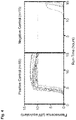
- a recombinant aggregated prion protein derived from a shear-force induced reaction of recombinant native prion protein with a post-mortem brain homogenate sample originating from a synucleopathy disease patient was mixed at a dilution of 1/100000 with 1.5 mg/ml native conformation human ⁇ -synuclein in PBS containing 1% Triton X-100 (positive control).
- the buffer composition and the procedural details were analogous to the previous disclosures WO 2012/110570 A1 and WO 2016/001334 A1 .
- the Fluorophore used for aggregated prion protein detection was Thioflavin T.
- the same reaction composition was used without the addition of recombinant aggregated prion protein.
- the vessel generally corresponded to Fig. 1 .
- the gap width between the stator and the rotor was 0.3 mm and the diameter of the rotor was 3 mm.
- the utilized processing frequency was 400 revolutions per second (400 Hz) and the reaction temperature was set to 30°C, corresponding to a shear-rate of 12570 per second and to a shear-stress of 11.2 pascal.
- the reaction was followed for 15 hours corresponding to 180 cycles of processing and resting. In each cycle, the processing was applied for three seconds, followed by a resting phase of 297 seconds. Fluorescence signals of Thioflavin T were accumulated during the resting phase of each cycle to detect the build-up of aggregated prion protein. For each, positive control and negative control, data-traces for 15 replicas were recorded.
- detection can be measured through the detection section of the vessel by the change of fluorescence of a fluorescent dye added to the mixture, the dye being specific for aggregated conformation prion protein.
- exemplary dyes are e.g. Thioflavin T, Thioflavin S, Congo Red, thiophene-based amyloid ligands like luminescent conjugated polythiophenes (LCP), polythiophene acetic acid (PTAA) and luminescent conjugated oligothiophenes (LCO), Pittsburgh compound B, Aminonaphthalene 2-Cyanoacrylate (ANCA) probes, pegylated phenylbenzoxazole derivatives, Pinacyanol, Chrysamine G, and dyes containing at least one of the following scaffolds: Chalcone, Flavone, Aurone, Stilbene, Diphenyl-1,2,4-oxadiazole, Diphenyl-1,3,4-oxadiazole, Benzothiazole, Benzoo
- the native conformation prion protein can be labelled with a fluorescent dye, e.g. by binding of a fluorescent dye to the native conformation prion protein directly or by an intermediate spacer, e.g. fluorophore derivatives that contain reactive chemical groups such as isothiocyanates (reactive to primary amines, e.g. Lysines), succinylimide esters (reactive towards amino groups to form amido bonds, e.g. N-terminal amino acids), maleimide (reactive to free sulfhydryl groups, e.g. cysteine).
- a fluorescent dye e.g. by binding of a fluorescent dye to the native conformation prion protein directly or by an intermediate spacer, e.g. fluorophore derivatives that contain reactive chemical groups such as isothiocyanates (reactive to primary amines, e.g. Lysines), succinylimide esters (reactive towards amino groups to form amido bonds, e.g. N-terminal amino
- fluorophore derivatives include cyanines, flurescein, rhodamine, Alexa Fluors, Dylight fluors, ATTO-Tec Dyes, BODIPY Dyes, SETA Dyes, SeTau Dyes, DYOMICS Dyes.
Landscapes
- Chemical & Material Sciences (AREA)
- Health & Medical Sciences (AREA)
- Chemical Kinetics & Catalysis (AREA)
- Life Sciences & Earth Sciences (AREA)
- Engineering & Computer Science (AREA)
- Hematology (AREA)
- Immunology (AREA)
- Biomedical Technology (AREA)
- General Health & Medical Sciences (AREA)
- Analytical Chemistry (AREA)
- Molecular Biology (AREA)
- Urology & Nephrology (AREA)
- Clinical Laboratory Science (AREA)
- Medicinal Chemistry (AREA)
- Biotechnology (AREA)
- Physics & Mathematics (AREA)
- Microbiology (AREA)
- Biochemistry (AREA)
- Cell Biology (AREA)
- General Physics & Mathematics (AREA)
- Pathology (AREA)
- Food Science & Technology (AREA)
- Dispersion Chemistry (AREA)
- Neurology (AREA)
- Neurosurgery (AREA)
- Proteomics, Peptides & Aminoacids (AREA)
- Investigating Or Analysing Biological Materials (AREA)
- Optical Measuring Cells (AREA)
- Automatic Analysis And Handling Materials Therefor (AREA)
- Devices For Use In Laboratory Experiments (AREA)
Priority Applications (7)
| Application Number | Priority Date | Filing Date | Title |
|---|---|---|---|
| EP21183830.5A EP4115976A1 (fr) | 2021-07-05 | 2021-07-05 | Cuvette de réaction |
| PCT/EP2022/068360 WO2023280731A1 (fr) | 2021-07-05 | 2022-07-03 | Récipient de réaction |
| KR1020247004105A KR20240028520A (ko) | 2021-07-05 | 2022-07-03 | 반응 용기 |
| US18/575,955 US20240329059A1 (en) | 2021-07-05 | 2022-07-03 | Reaction vessel |
| CA3223225A CA3223225A1 (fr) | 2021-07-05 | 2022-07-03 | Recipient de reaction |
| AU2022309106A AU2022309106A1 (en) | 2021-07-05 | 2022-07-03 | Reaction vessel |
| JP2024500543A JP2024527736A (ja) | 2021-07-05 | 2022-07-03 | 反応容器 |
Applications Claiming Priority (1)
| Application Number | Priority Date | Filing Date | Title |
|---|---|---|---|
| EP21183830.5A EP4115976A1 (fr) | 2021-07-05 | 2021-07-05 | Cuvette de réaction |
Publications (1)
| Publication Number | Publication Date |
|---|---|
| EP4115976A1 true EP4115976A1 (fr) | 2023-01-11 |
Family
ID=76807525
Family Applications (1)
| Application Number | Title | Priority Date | Filing Date |
|---|---|---|---|
| EP21183830.5A Pending EP4115976A1 (fr) | 2021-07-05 | 2021-07-05 | Cuvette de réaction |
Country Status (7)
| Country | Link |
|---|---|
| US (1) | US20240329059A1 (fr) |
| EP (1) | EP4115976A1 (fr) |
| JP (1) | JP2024527736A (fr) |
| KR (1) | KR20240028520A (fr) |
| AU (1) | AU2022309106A1 (fr) |
| CA (1) | CA3223225A1 (fr) |
| WO (1) | WO2023280731A1 (fr) |
Citations (2)
| Publication number | Priority date | Publication date | Assignee | Title |
|---|---|---|---|---|
| WO2012110570A1 (fr) | 2011-02-16 | 2012-08-23 | Helmholtz-Zentrum für Infektionsforschung GmbH | Dispositif et procédé de production et d'analyse de prions |
| WO2016001334A1 (fr) | 2014-07-01 | 2016-01-07 | Senostic Gmbh | Procédé pour le diagnostic de maladies neurodégénératives |
-
2021
- 2021-07-05 EP EP21183830.5A patent/EP4115976A1/fr active Pending
-
2022
- 2022-07-03 US US18/575,955 patent/US20240329059A1/en active Pending
- 2022-07-03 KR KR1020247004105A patent/KR20240028520A/ko unknown
- 2022-07-03 JP JP2024500543A patent/JP2024527736A/ja active Pending
- 2022-07-03 AU AU2022309106A patent/AU2022309106A1/en active Pending
- 2022-07-03 WO PCT/EP2022/068360 patent/WO2023280731A1/fr active Application Filing
- 2022-07-03 CA CA3223225A patent/CA3223225A1/fr active Pending
Patent Citations (2)
| Publication number | Priority date | Publication date | Assignee | Title |
|---|---|---|---|---|
| WO2012110570A1 (fr) | 2011-02-16 | 2012-08-23 | Helmholtz-Zentrum für Infektionsforschung GmbH | Dispositif et procédé de production et d'analyse de prions |
| WO2016001334A1 (fr) | 2014-07-01 | 2016-01-07 | Senostic Gmbh | Procédé pour le diagnostic de maladies neurodégénératives |
Also Published As
| Publication number | Publication date |
|---|---|
| AU2022309106A1 (en) | 2024-02-01 |
| KR20240028520A (ko) | 2024-03-05 |
| CA3223225A1 (fr) | 2023-01-12 |
| WO2023280731A1 (fr) | 2023-01-12 |
| US20240329059A1 (en) | 2024-10-03 |
| JP2024527736A (ja) | 2024-07-26 |
Similar Documents
| Publication | Publication Date | Title |
|---|---|---|
| US20200309794A1 (en) | Shear Force Generating Device for Analysis of Biopsied Mammalian Samples | |
| CN106170696B (zh) | 来自小样品体积的成形血液组分沉降速率的快速测量 | |
| CN104483434B (zh) | 一种用于100个以内细胞的蛋白质组自动化分析系统及方法 | |
| EP4115976A1 (fr) | Cuvette de réaction | |
| CN105751104A (zh) | 改进的同步辐射光源原位成像的疲劳试验机夹持机构 | |
| Tiiman et al. | Amyloidogenic nanoplaques in blood serum of patients with Alzheimer’s disease revealed by time-resolved thioflavin T fluorescence intensity fluctuation analysis | |
| Zinellu et al. | Simultaneous analysis of kynurenine and tryptophan in human plasma by capillary electrophoresis with UV detection | |
| Luchinat et al. | Determination of intracellular protein–ligand binding affinity by competition binding in-cell NMR | |
| EP4389272A1 (fr) | Cuve de réaction avec insert de stator et rotor | |
| US6403328B1 (en) | Method of measuring erythrocyte sedimentation rate (ESR) or plasma fibrinogen of a blood sample | |
| CN109716107B (zh) | 用于确定微生物病原体的组合的光学光谱法 | |
| CN204064891U (zh) | 一种紫色分光计的比色皿架 | |
| US20090265184A1 (en) | Method for the fractionation and separation of particles by step-wise gradient density extraction | |
| Bai et al. | Advanced techniques for detecting protein misfolding and aggregation in cellular environments | |
| IE59838B1 (en) | Consistometer for the analysis of rheological change | |
| CN105441321A (zh) | 全自动一体化核酸分析仪 | |
| HUE035632T2 (en) | Procedure for Prion Production and Analysis | |
| Lehmann et al. | Simultaneous, quantitative analysis of UDP‐N‐acetylglucosamine, UDP‐N‐acetylgalactosamine, UDP‐glucose and UDP‐galactose in human peripheral blood cells, muscle biopsies and cultured mesangial cells by capillary zone electrophoresis | |
| JP2014514540A (ja) | 感染の早期診断およびモニタリングのための白血球の自己蛍光を使用した細胞学的方法 | |
| CN210894174U (zh) | 一种光谱仪用采样装置 | |
| CN109722378A (zh) | 一种食品细菌含量检测装置 | |
| CN109239324A (zh) | 一种血液活性检测设备 | |
| CN112462048A (zh) | 微流控检测装置 | |
| CN210571962U (zh) | 实时原位生物样本检测仪 | |
| US3937581A (en) | Analytic cell for use in high-speed ultra centrifuges |
Legal Events
| Date | Code | Title | Description |
|---|---|---|---|
| PUAI | Public reference made under article 153(3) epc to a published international application that has entered the european phase |
Free format text: ORIGINAL CODE: 0009012 |
|
| STAA | Information on the status of an ep patent application or granted ep patent |
Free format text: STATUS: THE APPLICATION HAS BEEN PUBLISHED |
|
| AK | Designated contracting states |
Kind code of ref document: A1 Designated state(s): AL AT BE BG CH CY CZ DE DK EE ES FI FR GB GR HR HU IE IS IT LI LT LU LV MC MK MT NL NO PL PT RO RS SE SI SK SM TR |
|
| 19U | Interruption of proceedings before grant |
Effective date: 20221101 |
|
| 19W | Proceedings resumed before grant after interruption of proceedings |
Effective date: 20230801 |
|
| STAA | Information on the status of an ep patent application or granted ep patent |
Free format text: STATUS: REQUEST FOR EXAMINATION WAS MADE |
|
| 17P | Request for examination filed |
Effective date: 20230613 |
|
| RBV | Designated contracting states (corrected) |
Designated state(s): AL AT BE BG CH CY CZ DE DK EE ES FI FR GB GR HR HU IE IS IT LI LT LU LV MC MK MT NL NO PL PT RO RS SE SI SK SM TR |
|
| RAP1 | Party data changed (applicant data changed or rights of an application transferred) |
Owner name: ALOIS DATA GMBH |