EP4115812A1 - Intraoral-röntgensystem mit funktionsweiche im röntgengerät zur verwendung unterschiedlicher sensortypen - Google Patents
Intraoral-röntgensystem mit funktionsweiche im röntgengerät zur verwendung unterschiedlicher sensortypen Download PDFInfo
- Publication number
- EP4115812A1 EP4115812A1 EP21183848.7A EP21183848A EP4115812A1 EP 4115812 A1 EP4115812 A1 EP 4115812A1 EP 21183848 A EP21183848 A EP 21183848A EP 4115812 A1 EP4115812 A1 EP 4115812A1
- Authority
- EP
- European Patent Office
- Prior art keywords
- ray
- intraoral
- exposure
- sensor
- mode
- Prior art date
- Legal status (The legal status is an assumption and is not a legal conclusion. Google has not performed a legal analysis and makes no representation as to the accuracy of the status listed.)
- Granted
Links
Images


Classifications
-
- A—HUMAN NECESSITIES
- A61—MEDICAL OR VETERINARY SCIENCE; HYGIENE
- A61B—DIAGNOSIS; SURGERY; IDENTIFICATION
- A61B6/00—Apparatus or devices for radiation diagnosis; Apparatus or devices for radiation diagnosis combined with radiation therapy equipment
- A61B6/50—Apparatus or devices for radiation diagnosis; Apparatus or devices for radiation diagnosis combined with radiation therapy equipment specially adapted for specific body parts; specially adapted for specific clinical applications
- A61B6/51—Apparatus or devices for radiation diagnosis; Apparatus or devices for radiation diagnosis combined with radiation therapy equipment specially adapted for specific body parts; specially adapted for specific clinical applications for dentistry
- A61B6/512—Intraoral means
-
- A—HUMAN NECESSITIES
- A61—MEDICAL OR VETERINARY SCIENCE; HYGIENE
- A61B—DIAGNOSIS; SURGERY; IDENTIFICATION
- A61B6/00—Apparatus or devices for radiation diagnosis; Apparatus or devices for radiation diagnosis combined with radiation therapy equipment
- A61B6/54—Control of apparatus or devices for radiation diagnosis
- A61B6/542—Control of apparatus or devices for radiation diagnosis involving control of exposure
-
- A—HUMAN NECESSITIES
- A61—MEDICAL OR VETERINARY SCIENCE; HYGIENE
- A61B—DIAGNOSIS; SURGERY; IDENTIFICATION
- A61B6/00—Apparatus or devices for radiation diagnosis; Apparatus or devices for radiation diagnosis combined with radiation therapy equipment
- A61B6/56—Details of data transmission or power supply, e.g. use of slip rings
- A61B6/563—Details of data transmission or power supply, e.g. use of slip rings involving image data transmission via a network
Definitions
- the present invention relates to an intraoral x-ray system with automatic exposure control (AEC) functionality, consisting of an intraoral x-ray sensor and a dental x-ray device.
- AEC automatic exposure control
- the automatic exposure control namely the AEC (automatic exposure control) technique is previously known, also in the dental field for intraoral X-rays with digital X-ray image receivers, see eg EP1859659A1 and U.S. 6,898,268 B2 .
- X-ray image detectors have an optimized dynamic range for typical exposure situations in intraoral X-ray diagnostics. Underexposed images are characterized by increased noise, overexposed areas can no longer resolve the signal due to saturation effects of the pixels. With the help of AEC technology, the saturation limit can be resolved by multiple exposures and summing up of the individual shots. By lowering the saturation limit, the X-ray image receptor can be optimized for low exposures. With this constellation, the user can specify the required minimum image quality depending on the indication in order to keep the patient dose as low as possible.
- the exposure situation can be measured with a scout shot.
- Information on the degree of exposure of this first shot is used for this purpose. These indicate which maximum value of a certain number of pixels has been reached or exceeded. It can also be a relative value related to a maximum allowable value, e.g. as a percentage of the saturation limit.
- the respective histogram can also contain information on the degree of exposure.
- the intraoral X-ray device with AEC functionality is connected to a computer or a cloud.
- the X-ray sensor which is set to readiness for exposure, captures the X-ray image. After exposure, the X-ray image data is read out from the X-ray detector and forwarded to the computer.
- One aim of the present invention is to provide an intraoral x-ray sensor with integrated AEC functionality.
- Another object of the present invention is to provide an intraoral X-ray system with mode switching that allows the use of different types of sensors, including an intraoral X-ray sensor with or without AEC functionalities.
- the intraoral x-ray system includes an intraoral x-ray device that is equipped with an automatic exposure control (AEC) functionality and can be connected to a cloud and a computer. At least one intraoral X-ray sensor can be connected to the X-ray device. Furthermore, the X-ray machine has a Functional switch, which detects the sensor type of at least one connected X-ray sensor in an initial identification process and activates an associated mode.
- the intraoral x-ray system comprises one or more of the following modes: a mode for detecting an exposure degree on the intraoral x-ray sensor side, a mode for detecting an exposure degree on the intraoral x-ray device, computer or cloud side, a mode without detecting an exposure degree.
- AEC Plus mode and an intraoral X-ray sensor with exposure level detection for use with an X-ray system with AEC functionality :
- the analysis of the scout image or video stream with regard to the degree of exposure is carried out by the IO X-ray sensor, not by the IO X-ray device or other system components such as a computer.
- the video stream can be used, for example, as an independent sequence of individual images.
- An essential feature of the present invention is that the electronics associated with the IO X-ray sensor (e.g. exposure analysis unit) are able to record information on the degree of exposure of the scout image or video stream and communicate this information to the IO X-ray device. This reduces the initialization effort and speeds up the process.
- the electronics associated with the IO X-ray sensor e.g. exposure analysis unit
- the IO X-ray device uses this information about the degree of exposure and other specifications, preferably sensor-specific properties, required image quality, indication, kV adjustment with dual energy, increased dynamic range (HDR), dose-dependent noise behavior, etc .to define exposure parameters, e.g. number of exposures, exposure time, tube current and tube voltage, for the subsequent exposure. This could be one more exposure, multiple exposures, or no further exposures.
- exposure parameters e.g. number of exposures, exposure time, tube current and tube voltage, for the subsequent exposure. This could be one more exposure, multiple exposures, or no further exposures.
- the exposure is preferably terminated by the x-ray device.
- the IO X-ray sensor head or the IO X-ray sensor connector is the preferred possible location for the evaluation unit (e.g. exposure analysis unit).
- said sensor head could be wirelessly connected to the IO X-ray device so that no plug is required.
- AEC mode and an intraoral X-ray sensor with no exposure level detection for use with an X-ray system with AEC functionality are described.
- the analysis of the scout image or video stream with regard to the degree of exposure is only carried out by the X-ray device or by other system components.
- the AEC Plus mode differs from the AEC mode, in which the above-mentioned evaluation takes place in the X-ray sensor and not in the IO X-ray device.
- no analysis of the scout image or video stream with regard to the degree of exposure is carried out either by the intraoral X-ray sensor or by the X-ray device/system.
- the intraoral X-ray system (3) includes an intraoral X-ray device (2) that is equipped with an automatic exposure control (AEC) functionality, and optionally with a cloud (6) and a computer ( 4.1) can be connected, at least one intraoral X-ray sensor (1; 1';1") being connectable to the X-ray device (2), and the X-ray device (2) has a functional switch (2.10) which, in an initial identification process, identifies the sensor type of the at least a connected intraoral X-ray sensor (1; 1';1"), and activates an associated mode (M; M';M").
- AEC automatic exposure control
- M associated mode
- the intraoral X-ray system (3) includes one or more of the following modes (M; M";M"): a mode (M") for intraoral x-ray sensor-side detection of an exposure degree, a mode (M') for intraoral x-ray device, computer or cloud-side detection of an exposure degree, a mode (M) without detection of an exposure degrees.
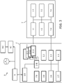
- Fig.3 shows a schematic representation of an intraoral X-ray system (3) according to an embodiment of the invention.
- the intraoral X-ray system (3) has an intraoral X-ray device (2), which is connected to an intraoral X-ray sensor (1") via the communication points (2.1.1; 1.1).
- the connection is preferably a cable connection.
- the IO X-ray sensor (1") consists of a sensor head (housing), cable and connector.
- the IO X-ray sensor (1") is connected to the intraoral X-ray device (2) via this plug. Additional X-ray sensors (1, 1', 1") with or without AEC functionality, different Type to be connected via their connector.
- the intraoral X-ray sensor (1") has a communication interface (1.1), an exposure analysis unit (1.2), an imaging X-ray detector (1.3), a controller (1.4), a memory (1.5), which contains sensor-specific properties, and a Image memory (1.6).
- the image memory (1.6) partially or completely stores the image data received from the imaging X-ray detector (1.3). signal loss is unacceptable for reasons of radiation hygiene.
- the x-ray sensor (1") can be equipped with a battery and wireless communication. This allows you to do without a cable.
- a wired data communication and/or power supply can also be considered as an alternative.
- a USB interface or Power over Ethernet (PoE) is available as a standard.
- the intraoral X-ray sensor (1") contains components for automatic exposure control (AEC) functionality, which is explained in more detail below.
- AEC automatic exposure control
- the scout shot or scout video stream received from the imaging X-ray detector (1.3) is processed by the exposure analysis unit (1.2) analyzed locally in the intraoral X-ray sensor (1") to collect information on the degree of exposure.
- the analysis result including the information on the degree of exposure, is forwarded to the intraoral X-ray device (2) or to another external device (eg a computer) via the communication interface (1.1).
- the intraoral X-ray device (2) has corresponding communication interfaces (2.1.1; 2.5).
- the intraoral X-ray device (2) has a decision-making unit (2.2) that evaluates the analysis result, including the recorded information on the degree of exposure, and decides on the sequence of further exposures, in particular the number of shots and their duration. In the case of a video stream, this can also be done during the ongoing exposure. When using a video stream, the first shot and second shot expand to the set of first "m" shots and second "n” shots. In this case, the process can also be repeated several times.
- the IO X-ray sensor (1") remains ready for exposure until the end of the exposure session.
- the intraoral X-ray device (2) also has an X-ray emitter (2.3), a power supply and high-voltage source (2.6) and a controller (2.4).
- the Decision unit (2.2) is also designed to take sensor-specific properties and/or image quality parameters specified by the user into account. which allow no or limited digitization of the analog exposure signal.
- the image quality parameters can be entered by the user directly or indirectly through a user interface (2.7) on the X-ray device (2).
- An indirect specification can be made via the medical indication (e.g. clarification of suspected caries, paradentosis, root course) successful gene, which is implemented by the intraoral X-ray system (3) with the decision unit (2.2) in exposure parameters, such as maximum exposure, dual energy, etc..
- this can also be done via a user interface (4.2) of a computer (4.1) on the intraoral -X-ray machine (2) is connected.
- the intraoral X-ray device (2) is connected to the computer (4.1) with its communication interface (2.5) and preferably via a network (5).
- the intraoral X-ray device (2) and the computer (4.1) can also have a connection to a cloud (6).
- the raw image material received is processed into a first raw image in order to compensate for sensor- and recording-specific imperfections. These are: gain, blemish and DC correction (classic), dynamic expansion (HDR), motion artifact compensation (anti-shake).
- gain, blemish and DC correction classic
- HDR dynamic expansion
- anti-shake anti-shake
- the intraoral X-ray device (2) has an exposure analysis unit (2.8), but this is not required because the IO X-ray sensor (1") carries out the evaluation itself.
- the other framed components are also thick not mandatory.
- the Communication interfaces (2.1.1) to (2.1.3) provided separately or alternatively as a common communication interface.
- Fig.2 shows a schematic representation of an intraoral X-ray system (3) according to a further embodiment of the invention.
- the intraoral X-ray system (3) has an intraoral X-ray device (2) which is connected to an intraoral X-ray sensor (1') via the communication points (2.1.2; 1.1).
- the connection is preferably a cable connection.
- the IO X-ray sensor (1') consists of a sensor head (housing), cable and connector.
- the IO X-ray sensor (1') is connected to the intraoral X-ray device (2) via this plug.
- Additional sensors (1, 1′, 1′′) with or without AEC functionality can preferably be connected to the IO X-ray device (2) at the same time via their plugs.
- a wireless connection can be used.
- the intraoral X-ray sensor (1′) has a Communication interface (1.1), no exposure analysis unit (1.2), an imaging X-ray detector (1.3), a controller (1.4), and a memory (1.5), which contains the sensor-specific properties.
- the X-ray sensor (1 ') with a battery and wireless communication. This means that there is no need for a cable. Wired data communication and/or energy supply can also be considered as an alternative.
- a USB interface or Power over Ethernet (PoE) is available as a standard.
- the intraoral x-ray sensor (1') does not contain any components for an automatic exposure control (AEC) functionality.
- the scout shot or scout video stream received from the imaging X-ray detector (1.3) is analyzed locally in the X-ray device (2) by the exposure analysis unit (2.8) in order to record information on the degree of exposure.
- the intraoral X-ray device (2) has a decision-making unit (2.2) that evaluates the analysis result, including the recorded information on the degree of exposure, and decides on the sequence of further exposures, in particular the number of shots and their duration. In the case of a video stream, this can also be done during the ongoing exposure.
- the first shot and second shot expand to the set of first "m" shots and second "n" shots.
- the process can also be repeated several times.
- the IO X-ray sensor (1') remains ready for recording until the end of the recording session.
- the intraoral X-ray device (2) also has an X-ray emitter (2.3), a power supply and high-voltage source (2.6) and a controller (2.4).
- the decision unit (2.2) is also designed to take into account the sensor-specific properties and/or image quality parameters specified by the user.
- the sensor-specific properties include information on sensor dimensions, local pixel errors, dose/signal behavior and the maximum saturation level above which saturation effects occur that allow no or limited digitization of the analog exposure signal.
- the image quality parameters can be entered by the user directly or indirectly through a user interface (2.7) on the X-ray device (2).
- An indirect specification can be made via the medical indication (e.g. clarification of suspected caries, paradentosis, root course), which is converted into exposure parameters by the intraoral X-ray system (3) with the decision unit (2.2), e.g. maximum exposure, dual energy etc..
- this can also be done via a user interface (4.2) of a computer (4.1) that is connected to the intraoral X-ray device (2).
- the intraoral X-ray device (2) is connected to a computer (4.1) with its communication interface (2.5) and preferably via a network (5).
- the intraoral X-ray device (2) and the computer (4.1) can also have a connection to a cloud (6).
- the raw image material received is processed into a first raw image in order to compensate for sensor- and recording-specific imperfections.
- the X-ray device (2) also has an image memory (2.9).
- the communication interfaces (2.1.1) to (2.1.3) are preferably provided separately or alternatively as a common communication interface.
- Fig.1 shows a schematic representation of an intraoral X-ray system (3) according to a further embodiment of the invention.
- the intraoral X-ray system (3) has an intraoral X-ray device (2) with an intraoral X-ray sensor (1) is connected via the communication points (2.1.3; 1.1).
- the connection is preferably a cable connection.
- the IO X-ray sensor (1) consists of a sensor head (housing), cable and connector.
- the IO X-ray sensor (1) is connected to the intraoral X-ray device (2) via this connector.
- a further 10 x-ray sensors (1, 1′, 1′′) with or without AEC functionality can preferably be connected to the IO x-ray device (2) at the same time via their plugs.
- a wireless connection can be used.
- the intraoral x-ray sensor (1) has a Communication interface (1.1), no exposure analysis unit (1.2), an imaging X-ray detector (1.3), a controller (1.4), a memory (1.5) that contains the sensor-specific properties.
- the IO X-ray sensor (1) with a battery and wireless communication. This means that there is no need for a cable. Wired data communication and/or energy supply can also be considered as an alternative.
- a USB interface or Power over Ethernet (PoE) is available as a standard.
- the intraoral X-ray sensor (1) does not contain any components for automatic exposure control (AEC) functionality.
- the IO X-ray sensor (1) remains ready for exposure until the end of the exposure session.
- the intraoral X-ray device (2) also has an X-ray emitter (2.3), a power supply and high-voltage source (2.6) and a controller (2.4).
- the intraoral X-ray device (2) is connected to a computer (4.1) with its communication interface (2.5) and preferably via a network (5).
- the intraoral X-ray device (2) and the computer (4.1) can also have a connection to a cloud (6). Instead of the X-ray sensor (1) or the X-ray device (2) carrying out image processing functions, this can be done in the PC (4.1).
- the X-ray device (2) can also have an image memory (2.9).
- the raw image material received is processed into a first raw image in order to compensate for sensor- and recording-specific imperfections. These are: gain, blemish and DC correction (classic), dynamic expansion (HDR), motion artifact compensation (anti-shake).
- the intraoral X-ray device (2) has an exposure analysis unit (2.8), but this is not required in this configuration. Furthermore, the other thick-framed components are not absolutely necessary.
- the communication interfaces (2.1.1) to (2.1.3) can preferably be provided separately or alternatively as a common communication interface.
Landscapes
- Health & Medical Sciences (AREA)
- Life Sciences & Earth Sciences (AREA)
- Engineering & Computer Science (AREA)
- Medical Informatics (AREA)
- Heart & Thoracic Surgery (AREA)
- Molecular Biology (AREA)
- Biophysics (AREA)
- Nuclear Medicine, Radiotherapy & Molecular Imaging (AREA)
- Optics & Photonics (AREA)
- Pathology (AREA)
- Radiology & Medical Imaging (AREA)
- Biomedical Technology (AREA)
- Physics & Mathematics (AREA)
- High Energy & Nuclear Physics (AREA)
- Surgery (AREA)
- Animal Behavior & Ethology (AREA)
- General Health & Medical Sciences (AREA)
- Public Health (AREA)
- Veterinary Medicine (AREA)
- Dentistry (AREA)
- Oral & Maxillofacial Surgery (AREA)
- Computer Networks & Wireless Communication (AREA)
- Apparatus For Radiation Diagnosis (AREA)
- X-Ray Techniques (AREA)
Abstract
Description
- Die vorliegende Erfindung bezieht sich auf ein Intraoral-Röntgensystem mit automatischer Belichtungskontrolle (AEC) Funktionalität, bestehend aus einem intraoralen Röntgensensor und einem dentalen Röntgengerät.
- Die automatischen Belichtungskontrolle, nämlich die AEC (automatic exposure control)-Technik ist vorbekannt, auch im Dentalbereich für intraorales Röntgen mit digitalen Röntgenbildempfängern, siehe z.B.
EP1859659A1 undUS 6,898,268 B2 . - Röntgenbilddetektoren haben für typische Belichtungssituationen in der Intraoral-Röntgendiagnostik einen optimierten Dynamikumfang. Unterbelichtete Aufnahmen zeichnen sich durch erhöhtes Rauschen aus, überbelichtete Bereiche können aufgrund von Sättigungseffekten der Pixel das Signal nicht mehr auflösen. Mit Hilfe der AEC-Technik kann die Sättigungsgrenze durch Mehrfachbelichtungen und Aufsummierung der Einzelaufnahmen aufgelöst werden. Durch das Senken der Sättigungsgrenze kann der Röntgenbildempfänger für niedrig-Belichtungen optimiert werden. Mit dieser Konstellation kann der Anwender indikationsabhängig die jeweils erforderliche Mindestbildqualität gezielt festlegen um die Patientendosis so niedrig wie möglich zu halten.
- Mit einem Scout Shot kann die Belichtungssituation ausgemessen werden. Dazu werden Informationen zum Belichtungsgrad dieser ersten Aufnahme herangezogen. Diese geben an, welcher Maximalwert einer bestimmten Anzahl an Pixeln erreicht oder überschritten wurde. Es kann auch ein relativer Wert mit Bezug zu einem maximal zulässigen Wert sein, z.B. in Prozent zur Sättigungsgrenze. Informationen zum Belichtungsgrad kann auch das jeweilige Histogramm beinhalten.
- Bei AEC-Röntgen Systemen mit Scout Shot ist eine schnelle Auswertung der vorbelichteten Aufnahmen zur Bestimmung der vollständigen Röntgenexposition erforderlich, um Bewegungsartefakte zu reduzieren, die durch Bewegungen der Aufnahmegeometrie während der Aufnahmesession hervorgerufen werden können. Bisher erfolgt die Auswertung des Belichtungsgrades des Scout Shots losgelöst vom Intraoral-Röntgensensor (im Folgenden auch kurz "Sensor" genannt) durch eine Auswerteeinheit, die im Röntgengerät (oder im angeschlossenen Rechner) angeordnet ist. Der bisherige Ablauf ist wie folgt:
- 1. Sensor erfasst den 1.ten Shot
- 2. Sensor überträgt teilweise oder vollständig den 1.ten Shot ans Röntgengerät
- 3. Auswerteeinheit analysiert 1. Shot im Röntgengerät
- 4. Auswerteeinheit legt Belichtungsgrad für den 2.ten Shot fest
- 5. Sensor erfasst den 2.ten Shot
- 6. Sensor überträgt den 2.ten Shot ans Röntgengerät
- 7. Auswerteeinheit berechnet im Röntgengerät aufsummiertes Bild aus den 1.ten Shot und 2.ten Shot
- Im Allgemeinen ist das Intraoral-Röntgengerät mit AEC-Funktionalität mit einem Rechner oder einer Cloud verbunden. Der in Aufnahmebereitschaft versetzte Röntgensensor erfasst das Röntgenbild. Nach der Belichtung werden die Röntgenbilddaten aus dem Röntgendetektor ausgelesen und an den Rechner weitergeleitet.
- Ein Ziel der vorliegenden Erfindung ist einen Intraoral-Röntgensensor mit integrierter AEC-Funktionalität bereitzustellen.
- Ein weiteres Ziel der vorliegenden Erfindung ist ein Intraoral-Röntgensystem mit Modusweiche bereitzustellen, dass die Verwendung unterschiedlicher Sensortypen ermöglicht, darunter auch ein Intraoral-Röntgensensor mit oder ohne AEC-Funktionalitäten.
- Diese Ziele werden durch ein Intraoral-Röntgensystem nach Anspruch 1 erreicht. Die Gegenstände der abhängigen Ansprüche beziehen sich auf Weiterentwicklungen und bevorzugte Ausführungsformen.
- Das erfindungsgemäße Intraoral-Röntgensystem umfasst ein Intraoral-Röntgengerät, das mit einer Automatischen Belichtungskontrolle (AEC) Funktionalität ausgestattet, und mit einer Cloud und einem Rechner verbindbar ist. An dem Röntgengerät ist mindestens ein Intraoral-Röntgensensor anschließbar. Ferner weist das Röntgengerät eine Funktionsweiche auf, welche in einem initialen Identifikationsprozess den Sensortyp des mindestens einem angeschlossenen Röntgensensors erkennt und einen dazugehörigen Modus aktiviert. Das Intraoral-Röntgensystem umfasst ein oder mehrere der folgenden Modi: ein Modus zur Intraoral-Röntgensensorseitigen Erfassung eines Belichtungsgrades, ein Modus zur Intraoral-Röntgengerät-, Rechner- oder Cloudseitigen Erfassung eines Belichtungsgrades, ein Modus ohne Erfassung eines Belichtungsgrades.
- In der nachfolgenden Beschreibung werden unterschiedliche Röntgensensortypen und die dazu gehörigen Modi erklärt.
- Gemäß der vorliegenden Erfindung wird in dem AEC Plus Modus die Analyse des Scout Bildes oder Video Streams hinsichtlich des Belichtungsgrades vom IO-Röntgensensor durchgeführt, nicht vom IO-Röntgengerät oder anderen Systemkomponenten, wie z.B. einem Rechner. Dazu kann der Video Stream z.B. als unabhängige Folge von Einzelbildern verwendet werden.
- Wird die oben genannte Auswertung in den IO-Röntgensensor (im Folgenden auch kurz "Sensor" genannt) verlagert reduziert sich der Datentransfer und die Komplexität auf der Seite des IO-Röntgengerätes. Der erfindungsgemäße Ablauf ist dann z.B. wie folgt:
- 1. Sensor erfasst den 1.ten Shot (Scout Shot);
- 2. Auswerteeinheit (z.B. eine Exposition Analyse-Einheit des Sensors) analysiert 1. Shot und stellt Informationen zum Belichtungsgrad zusammen;
- 3. Informationen zum Belichtungsgrad, sowie ggf. Sensoreigenschaften, werden an Entscheidungseinheit außerhalb des Sensors übertragen;
- 4. Entscheidungseinheit bestimmt anhand dieser und weiterer Informationen die Belichtungsparameter weiterer Shots;
- 5. Entsprechend dieser Entscheidung erfolgen keine, eine oder weitere Belichtungen, die der Sensor erfasst;
- 6. Sensor überträgt Einzelaufnahmen und/oder (optional) mindestens eine summierte Aufnahme an das IO-Röntgengerät bzw. PC.
- Ein wesentliches Merkmal der vorliegenden Erfindung ist, dass die dem IO-Röntgensensor zugeordnete Elektronik (z.B. Exposition Analyse-Einheit) in der Lage ist Informationen zum Belichtungsgrad des Scout Bildes oder Video Streams zu erfassen und diese Information dem IO-Röntgengerät mitzuteilen. Dadurch reduziert sich der Initialisierungsaufwand und der Ablauf wird beschleunigt.
- Das IO-Röntgengerät, insbesondere die Entscheidungseinheit des IO-Röntgengeräts oder anderer Systemkomponenten, verwendet diese Information des Belichtungsgrades und andere Vorgaben vorzugsweise sensorspezifische Eigenschaften, geforderte Bildqualität, Indikation, kV-Anpassung bei Dual Energy, erhöhte Dynamikbereich (HDR), Dosisabhängiges Rauschverhalten, usw. um daraus Belichtungsparameter z.B. Anzahl der Aufnahmen, Belichtungszeit, Röhrenstrom und Röhrenspannung, für nachfolgende Belichtung festzulegen. Dies könnte eine weitere Belichtung, aber auch mehrere oder keine weitere Belichtung sein.
- Im Fall eines Video Streams wird bei Erreichen eines von der Entscheidungseinheit des Röntgengeräts berechneten Wertes die Belichtung vom Röntgengerät vorzugsweise abgebrochen.
- Als mögliche Unterbringungsorte für die Auswerteeinheit (z.B. Exposition Analyse-Einheit) bietet sich vorzugsweise der IO-Röntgensensorkopf oder der IO-Röntgensensorstecker an. Alternativ könnte der genannte Sensorkopf mit dem IO-Röntgengerät drahtlos verbunden werden, so dass kein Stecker benötigt wird.
- Gemäß der vorliegenden Erfindung wird, in dem AEC Modus, die Analyse des Scout Bildes oder Video Streams hinsichtlich des Belichtungsgrades nur vom Röntgengerät oder von weiteren Systemkomponenten durchgeführt. Der AEC Plus Modus unterscheidet sich vom AEC Modus, in dem die oben erwähnte Auswertung im Röntgensensor stattfindet und nicht im IO-Röntgengerät.
- Gemäß der vorliegenden Erfindung wird in dem Standard Modus keine Analyse des Scout Bildes oder Video Streams hinsichtlich des Belichtungsgrades weder vom Intraoral-Röntgensensor noch vom Röntgengerät/System durchgeführt.
- In der nachfolgenden Beschreibung wird die vorliegende Erfindung anhand von Ausführungsbeispielen unter Bezugnahme auf die Zeichnungen näher erläutert, wobei
-
Abb.1 - ist eine schematische Darstellung eines Intraoral-Röntgensystems, an dem ein Standard IO-Röntgensensor zum Betrieb im Standard Modus angeschlossen ist; -
Abb.2 - ist eine schematische Darstellung eines Intraoral-Röntgensystems mit AEC Funktionalität an dem ein IO-Röntgensensor zum Betrieb im AEC Modus angeschlossen ist; -
Abb.3 - ist eine schematische Darstellung eines Intraoral-Röntgensystems mit AEC Funktionalität an dem ein IO-Röntgensensor zum Betrieb im AEC Plus Modus angeschlossen ist. - Die in den Abbildungen stark umrandeten Funktionsblöcke sind im jeweiligen Modus nicht zwingend aktiviert.
- Die in den Zeichnungen gezeigten Referenznummern bezeichnen die unten aufgeführten Elemente, auf die in der nachfolgenden Beschreibung der beispielhaften Ausführungsformen Bezug genommen wird.
- 1. Intraoral-Röntgensensor (Sensortyp für Standard Modus)
- 1' Intraoral-Röntgensensor (Sensortyp für AEC Modus)
- 1" Intraoral-Röntgensensor (Sensortyp für AEC Plus Modus)
- 1.1 Kommunikationsschnittstelle
- 1.2 Exposition Analyse-Einheit
- 1.3 Bildgebender Röntgendetektor
- 1.4 Steuerung
- 1.5 Sensorspezifische Eigenschaften
- 1.6 Bildspeicher
- 2. Röntgengerät
- 2.1.1 Kommunikationsschnittstelle
- 2.1.2 Kommunikationsschnittstelle
- 2.1.3 Kommunikationsschnittstelle
- 2.2 Entscheidungs-Einheit
- 2.3 Röntgen Strahler
- 2.4 Steuerung
- 2.5 Kommunikationsschnittstelle
- 2.6 Stromversorgung und Hochspannungsquelle
- 2.7 Benutzerschnittstelle
- 2.8 Exposition Analyse-Einheit
- 2.9 Bildspeicher
- 2.10 Funktionsweiche
- 3. Intraoral-Röntgensystem
- 4.1 Rechner
- 4.2 Benutzerschnittstelle und Bildschirm
- 5. Netzwerk
- 6. Cloud
- Wie in den Abbildungen 1 bis 3 unterschiedlicher Ausführungsformen gezeigt wurde umfasst das Intraoral-Röntgensystem (3) ein Intraoral-Röntgengerät (2) das mit einer Automatischen Belichtungskontrolle (AEC) Funktionalität ausgestattet ist, und optional mit einer Cloud (6) und einem Rechner (4.1) verbindbar ist, wobei an dem Röntgengerät (2) mindestens ein Intraoral-Röntgensensor (1; 1'; 1") anschließbar ist, und das Röntgengerät (2) eine Funktionsweiche (2.10) aufweist welche in einem initialen Identifikationsprozess den Sensortyp des mindestens einem angeschlossenen Intraoral-Röntgensensors (1; 1'; 1") erkennt, und einen dazugehörigen Modus (M; M'; M") aktiviert. Das Intraoral-Röntgensystem (3) umfasst ein oder mehrere der folgenden Modi (M; M"; M"): ein Modus (M") zur Intraoral-Röntgensensorseitigen Erfassung eines Belichtungsgrades, ein Modus (M') zur Intraoral-Röntgengerät-, Rechner- oder Cloudseitigen Erfassung eines Belichtungsgrades, ein Modus (M) ohne Erfassung eines Belichtungsgrades.
- Im Folgenden wird der Modus (M") erklärt, welcher den eingangsseitig erklärten AEC Plus Modus entspricht:
Abb.3 zeigt eine schematische Darstellung eines Intraoral-Röntgensystems (3) gemäß eines Ausführungsbeispiels der Erfindung. Das Intraoral-Röntgensystem (3) hat ein Intraoral-Röntgengerät (2), das mit einem Intraoral-Röntgensensor (1") über die Kommunikationsstellen (2.1.1; 1.1) verbunden ist. Die Verbindung ist vorzugsweise eine Kabelverbindung. Der IO-Röntgensensor (1") bestehet aus einem Sensorkopf (Gehäuse), Kabel und Stecker. Über diesen Stecker ist der IO-Röntgensensor (1") mit dem Intraoral-Röntgengerät (2) verbunden. Am IO-Röntgengerät (2) können vorzugsweise gleichzeitig weitere Röntgensensoren (1, 1', 1") mit oder ohne AEC Funktionalität, unterschiedlichen Typs über deren Stecker angeschlossen sein. Alternativ kann eine drahtlose Verbindung benutzt werden. Der Intraoral-Röntgensensor (1") hat eine Kommunikationsschnittstelle (1.1), eine Exposition Analyse-Einheit (1.2), einen bildgebenden Röntgendetektor (1.3), eine Steuerung (1.4), einen Speicher (1.5), der sensorspezifische Eigenschaften beinhaltet, und einen Bildspeicher (1.6). Der Bildspeicher (1.6) speichert die vom bildgebenden Röntgendetektor (1.3) empfangene Bilddaten teilweise oder vollständig. Der Bildspeicher (1.6) ist nützlich falls sich Pixelbilddaten aus dem bildgebenden Röntgendetektor (1.3) nicht ohne Signalverlust zur Auswertung auslesen lassen oder ein Signalverlust aus Gründen der Strahlenhygiene nicht akzeptabel ist. Vorzugsweise kann der Röntgensensor (1") mit einer Batterie und einer drahtlosen Kommunikation ausgestattet sein. Dies erlaubt auf ein Kabel zu verzichten. Eine kabelgebundene Datenkommunikation und/oder Energieversorgung kann auch alternativ berücksichtigt werden. Hier bietet sich als Standard eine USB-Schnittstelle oder Power over Ethernet (PoE) an. - Der Intraoral-Röntgensensor (1") beinhaltet Komponenten für eine automatische Belichtungskontrolle (AEC) Funktionalität, die im Folgenden naher erklärt wird. Der vom bildgebender Röntgendetektor (1.3) empfangene Scout Shot oder Scout Video Stream wird von der Exposition Analyse-Einheit (1.2) lokal im Intraoral-Röntgensensor (1") analysiert, um Informationen zum Belichtungsgrad zu erfassen. Das Analyseergebnis inklusive der Informationen zum Belichtungsgrad wird mittels der Kommunikationsschnittstelle (1.1) an das Intraoral Röntgengerät (2) bzw. an ein anderes externes Gerät (z.B. ein Rechner) weitergeleitet. Dazu hat das Intraoral-Röntgengerät (2) entsprechende Kommunikationsschnittstellen (2.1.1; 2.5). Das Intraoral-Röntgengerät (2) hat eine Entscheidungs-Einheit (2.2), die das Analyseergebnis inklusive der erfassten Information zum Belichtungsgrad auswertet und über die Abfolge weiterer Belichtungen insbesondere die Anzahl der Schüsse und deren Dauer entscheidet. Im Fall eines Video Streams kann dies auch während der laufenden Belichtung erfolgen. Bei der Verwendung eines Videostreams erweitert sich der erste Shot und zweite Shot auf die Menge von ersten "m" Shots und zweiten "n" Shots. In diesem Fall kann der Prozess auch mehrfach wiederholt werden. Der IO-Röntgensensor (1") bleibt bis zum Ende der Aufnahme-Session in entsprechender Aufnahmebereitschaft. Das Intraoral-Röntgengerät (2) hat ferner einen Röntgenstrahler (2.3), eine Stromversorgung und Hochspannungsquelle (2.6) und eine Steuerung (2.4). Die Entscheidungseinheit (2.2) ist ferner ausgebildet sensorspezifischen Eigenschaften und/oder vom Anwender vorgegebene Bildqualitätsparameter zu berücksichtigen. Die sensorspezifischen Eigenschaften umfassen Angaben u.a. zu Sensor-Dimensionen, zu lokalen Pixelfehlern, zum Dosis/Signal-Verhalten und zum maximalen Sättigungspegel ab dessen Überschreiten Sättigungseffekte eintreten, die keine oder eingeschränkte Digitalisierung des analogen Belichtungssignals erlauben. Die Bildqualitätsparameter können vom Benutzer direkt oder indirekt durch eine Benutzerschnittstelle (2.7) am Röntgengerät (2) eingegeben werden. Eine indirekte Vorgabe kann über die ärztliche Indikation (z.B. Klärung von Verdacht auf Karies, Paradentose, Wurzelverlauf) erfolgen, die vom Intraoral-Röntgensystem (3) mit der Entscheidungseinheit (2.2) in Belichtungsparameter umgesetzt wird, z.B. maximale Belichtung, Dual Energy etc.. Alternativ kann dies auch über eine Benutzerschnittstelle (4.2) eines Rechners (4.1) geschehen, der am Intraoral-Röntgengerät (2) angeschlossen ist. Das Intraoral-Röntgengerät (2) ist mit seiner Kommunikationsschnittstelle (2.5) und vorzugsweise über ein Netzwerk (5) mit dem Rechner (4.1) verbunden. Das Intraoral-Röntgengerät (2) und der Rechner (4.1) können auch eine Verbindung zu einer Cloud (6) haben. Das empfangene Rohbildmaterial wird zu einem ersten Rohbild aufgearbeitet, um sensor- und aufnahmespezifische Unzulänglichkeiten zu kompensieren. Diese sind: Gain, Blemish- und DC-Korrektur (klassisch), Dynamik-Erweiterung (HDR), Bewegungsartefakt-Kompensation (Anti-Shake). Anstelle, dass der IO-Röntgensensor oder das Röntgengerät (2) diese und weitere bildverarbeitende Funktionen unter Verwendung jeweiliger, interner Bildspeicher (2.9; 1.6) ausführt, kann dies in der Cloud (6) oder durch den PC (4.1) erfolgen.
- In diesem Ausführungsbeispiel verfügt das Intraoral-Röntgengerät (2) zwar über eine Exposition Analyse-Einheit (2.8), aber diese wird nicht benötigt, weil der IO-Röntgensensor (1") die Auswertung selbst ausführt. Ferner werden die dick andere umrandete Komponenten auch nicht zwingend benötigt. Vorzugsweise werden die Kommunikationsschnittstellen (2.1.1) bis (2.1.3) separat oder alternativ als eine gemeinsame Kommunikationsschnittstelle bereitgestellt.
- Im Folgenden wird der Modus (M') erklärt, welcher den eingangsseitig erklärten AEC Modus entspricht:
Abb.2 zeigt eine schematische Darstellung eines Intraoral-Röntgensystems (3) gemäß eines weiteren Ausführungsbeispiels der Erfindung. Das Intraoral-Röntgensystem (3) hat ein Intraoral-Röntgengerät (2), das mit einem Intraoral-Röntgensensor (1') über die Kommunikationsstellen (2.1.2;1.1) verbunden ist. Die Verbindung ist vorzugsweise eine Kabel Verbindung. Der IO-Röntgensensor (1') bestehet aus einem Sensorkopf (Gehäuse), Kabel und Stecker. Über diesen Stecker ist der IO-Röntgensensor (1') mit dem Intraoral-Röntgengerät (2) verbunden. Am IO-Röntgengerät (2) können vorzugsweise gleichzeitig weitere Sensoren (1, 1', 1") mit oder ohne AEC Funktionalität über deren Stecker angeschlossen sein. Alternativ kann eine drahtlose Verbindung benutzt werden. Der Intraoral-Röntgensensor (1') hat eine Kommunikationsschnittstelle (1.1), keine Exposition Analyse-Einheit (1.2), einen bildgebenden Röntgendetektor (1.3), eine Steuerung (1.4), und ein Speicher (1.5), der die Sensorspezifische Eigenschaften beinhaltet. Vorzugsweise kann der Röntgensensor (1') mit einer Batterie und einer drahtlosen Kommunikation ausgestattet sein. Dies erlaubt auf ein Kabel zu verzichten. Eine kabelgebundene Datenkommunikation und/oder Energieversorgung kann auch alternativ berücksichtigt werden. Hier bietet sich als Standard eine USB-Schnittstelle oder Power over Ethernet (PoE) an. - Der Intraoral-Röntgensensor (1') beinhaltet keine Komponenten für eine automatische Belichtungskontrolle (AEC) Funktionalität. Der vom bildgebenden Röntgendetektor (1.3) empfangene Scout Shot oder Scout Video Stream wird von der Exposition Analyse-Einheit (2.8) lokal im Röntgengerät (2) analysiert, um Informationen zum Belichtungsgrad zu erfassen. Das Intraoral-Röntgengerät (2) hat eine Entscheidungs-Einheit (2.2), die das Analyseergebnis inklusive der erfassten Information zum Belichtungsgrad auswertet und über die Abfolge weiterer Belichtungen insbesondere die Anzahl der Schüsse und deren Dauer entscheidet. Im Fall eines Video Streams kann dies auch während der laufenden Belichtung erfolgen. Bei der Verwendung eines Videostreams erweitert sich der erste Shot und zweite Shot auf die Menge von ersten "m" Shots und zweiten "n" Shots. In diesem Fall kann der Prozess auch mehrfach wiederholt werden. Der IO-Röntgensensor (1') bleibt bis zum Ende der Aufnahme-Session in entsprechender Aufnahmebereitschaft. Das Intraoral-Röntgengerät (2) hat ferner einen Röntgenstrahler (2.3), eine Stromversorgung und Hochspannungsquelle (2.6) und eine Steuerung (2.4). Die Entscheidungseinheit (2.2) ist ferner ausgebildet die sensorspezifischen Eigenschaften und/oder vom Anwender vorgegebene Bildqualitätsparameter zu berücksichtigen. Die Sensorspezifischen Eigenschaften umfassen Angaben u.a. zu Sensor-Dimensionen, zu lokalen Pixelfehlern, zum Dosis/Signal-Verhalten und zum maximalen Sättigungspegel ab dessen Überschreiten Sättigungseffekte eintreten, die keine oder eingeschränkte Digitalisierung des analogen Belichtungssignals erlauben. Die Bildqualitätsparameter können vom Benutzer direkt oder indirekt durch eine Benutzerschnittstelle (2.7) am Röntgengerät (2) eingegeben werden. Eine indirekte Vorgabe kann über die ärztliche Indikation (z.B. Klärung von Verdacht auf Karies, Paradentose, Wurzelverlauf) erfolgen, die vom Intraoral-Röntgensystem (3) mit der Entscheidungseinheit (2.2) in Belichtungsparameter umgesetzt wird, z.B. maximale Belichtung, Dual Energy etc.. Alternativ kann dies auch über eine Benutzerschnittstelle (4.2) eines Rechners (4.1) geschehen, der am Intraoral-Röntgengerät (2) angeschlossen ist. Das Intraoral-Röntgengerät (2) ist mit seiner Kommunikationsschnittstelle (2.5) und vorzugsweise über ein Netzwerk (5) mit einem Rechner (4.1) verbunden. Das Intraoral-Röntgengerät (2) und der Rechner (4.1) können auch eine Verbindung zu einer Cloud (6) haben. Das empfangene Rohbildmaterial wird zu einem ersten Rohbild aufgearbeitet, um sensor- und aufnahmespezifische Unzulänglichkeiten zu kompensieren. Diese sind: Gain, Blemish- und DC-Korrektur (klassisch), Dynamik-Erweiterung (HDR), Bewegungsartefakt-Kompensation (Anti-Shake). Anstelle, dass der Röntgensensor (1') oder das Röntgengerät (2) bildverarbeitende Funktionen ausführt, kann dies in der Cloud (6) oder durch den PC (4.1) erfolgen. Das Röntgengerät (2) hat auch einen Bildspeicher (2.9).
- Die Kommunikationsschnittstellen (2.1.1) bis (2.1.3) werden vorzugsweise separat oder alternativ als eine gemeinsame Kommunikationsschnittstellen bereitgestellt.
- Im Folgenden wird der Modus (M) erklärt, welcher den eingangsseitig erklärten Standard Modus entspricht:
Abb.1 zeigt eine schematische Darstellung eines Intraoral-Röntgensystems (3) gemäß eines weiteren Ausführungsbeispiels der Erfindung. Das Intraoral-Röntgensystem (3) hat ein Intraoral-Röntgengerät (2), das mit einem Intraoral-Röntgensensor (1) über die Kommunikationsstellen (2.1.3; 1.1) verbunden ist. Die Verbindung ist vorzugsweise eine Kabel Verbindung. Der IO-Röntgensensor (1) bestehet aus einem Sensorkopf (Gehäuse), Kabel und Stecker. Über diesen Stecker ist der IO-Röntgensensor (1) mit dem Intraoral-Röntgengerät (2) verbunden. Am IO-Röntgengerät (2) können vorzugsweise gleichzeitig weitere 10 Röntgensensoren (1, 1', 1") mit oder ohne AEC Funktionalität über deren Stecker angeschlossen sein. Alternativ kann eine drahtlose Verbindung benutzt werden. Der Intraoral-Röntgensensor (1) hat eine Kommunikationsschnittstelle (1.1), keine Exposition Analyse-Einheit (1.2), einen bildgebenden Röntgendetektor (1.3), eine Steuerung (1.4), ein Speicher (1.5), der die sensorspezifische Eigenschaften beinhaltet. Vorzugsweise kann der IO-Röntgensensor (1) mit einer Batterie und einer drahtlosen Kommunikation ausgestattet sein. Dies erlaubt auf ein Kabel zu verzichten. Eine kabelgebundene Datenkommunikation und/oder Energieversorgung kann auch alternativ berücksichtigt werden. Hier bietet sich als Standard eine USB-Schnittstelle oder Power over Ethernet (PoE) an. - Der Intraoral-Röntgensensor (1) beinhaltet keine Komponenten für eine automatische Belichtungskontrolle (AEC) Funktionalität. Der IO-Röntgensensor (1) bleibt bis zum Ende der Aufnahme-Session in entsprechender Aufnahmebereitschaft. Das Intraoral-Röntgengerät (2) hat ferner einen Röntgenstrahler (2.3), eine Stromversorgung und Hochspannungsquelle (2.6) und eine Steuerung (2.4).
- Das Intraoral-Röntgengerät (2) ist mit seiner Kommunikationsschnittstelle (2.5) und vorzugsweise über ein Netzwerk (5) mit einem Rechner (4.1) verbunden. Das Intraoral-Röntgengerät (2) und der Rechner (4.1) können auch eine Verbindung zu einer Cloud (6) haben. Anstelle, dass der Röntgensensor (1) oder das Röntgengerät (2) bildverarbeitende Funktionen ausführt, kann dies in dem PC (4.1) erfolgen. Das Röntgengerät (2) kann auch einen Bildspeicher (2.9) haben. Das empfangene Rohbildmaterial wird zu einem ersten Rohbild aufgearbeitet, um sensor- und aufnahmespezifische Unzulänglichkeiten zu kompensieren. Diese sind: Gain, Blemish- und DC-Korrektur (klassisch), Dynamik-Erweiterung (HDR), Bewegungsartefakt-Kompensation (Anti-Shake).
- In diesem Ausführungsbeispiel verfügt das Intraoral-Röntgengerät (2) zwar eine Exposition Analyse-Einheit (2.8), aber diese wird in dieser Konstellation nicht benötigt. Ferner werden die andere dick umrandete Komponenten auch nicht zwingend benötigt. Die Kommunikationsschnittstellen (2.1.1) bis (2.1.3) können vorzugsweise separat oder alternativ als eine gemeinsame Kommunikationsschnittstelle bereitgestellt werden.
- In der vorliegenden Erfindung wurden drei Modi vorgestellt. Vorstellbar sind auch weitere Modi mit zugehörigen Sensortypen. Weitere Kommunikationsschnittstellen können separat hinzugefügt werden. Je nach deren Funktionalität werden mehr oder weniger Funktionskomponenten des Röntgengerätes (2) oder Röntgensystems (3) ansprechbar. Die Funktionsweiche (2.10) identifiziert den jeweiligen Sensortyp, aktiviert den entsprechenden Modus Modi (M; M'; M"), um die erweiterten Funktionskomponenten auch einzubinden.
Claims (4)
- Intraoral-Röntgensystem (3) umfassend:ein Intraoral-Röntgengerät (2) das mit einer automatischen Belichtungskontrolle (AEC) Funktionalität ausgestattet ist, und mit einer Cloud (6) und einem Rechner (4.1) verbindbar ist, gekennzeichnet dadurch dassan dem Intraoral-Röntgengerät (2) mindestens ein Intraoral-Röntgensensor (1; 1'; 1") anschließbar ist, unddas Intraoral-Röntgengerät (2) eine Funktionsweiche (2.10) aufweist, welche in einem initialen Identifikationsprozess den Sensortyp des mindestens einem angeschlossenen intraoralen Röntgensensors (1; 1'; 1") erkennt und einen dazugehörigen Modus (M; M'; M") aktiviert, wobei das Intraoral-Röntgensystem (3) ein oder mehrere der folgenden Modi (M; M'; M") umfasst: ein Modus (M") zur Intraoral-Röntgensensorseitigen Erfassung eines Belichtungsgrades, ein Modus (M') zur Intraoral-Röntgengerät-, Rechner- oder Cloudseitigen Erfassung eines Belichtungsgrades, ein Modus (M) ohne Erfassung eines Belichtungsgrades.
- Intraoral-Röntgensystem (3) nach Anspruch 1, gekennzeichnet dadurch dass es den Modus (M") zur Intraoral-Röntgensensorseitigen Erfassung eines Belichtungsgrades und einen zugehörigen Intraoral-Röntgensensor (1") aufweist, der eine Exposition Analyse-Einheit (1.2), einen bildgebenden Röntgendetektor (1.3), und eine Kommunikationsschnittstelle (1.1) beinhaltet, wobei der vom bildgebenden Röntgendetektor (1.3) empfangene Scout Shot oder Scout Video Stream von der Exposition Analyse-Einheit (1.2) im Intraoral-Röntgensensor (1") analysiert wird, um Informationen über den Belichtungsgrad des Scout Bildes oder Video Streams zu erfassen und um diese mittels der Kommunikationsschnittstelle (1.1) an eine vom Intraoral-Röntgensensor (1) extern angeordnete Entscheidungseinheit (2.2) des Intraoral-Röntgengeräts (2) oder eines anderen Gerätes zur Auswertung und Entscheidung weiterer Belichtungen weiterzuleiten.
- Intraoral-Röntgensystem (3) nach Anspruch 1 oder 2, gekennzeichnet dadurch dass es den Modus (M') zur Intraoral-Röntgengerät-, Rechner-, oder Cloudseitigen Erfassung eines Belichtungsgrades und einen zugehörigen Intraoral-Röntgensensor (1') aufweist, der keine Informationen zum Belichtungsgrad erfasst, und der einen bildgebenden Röntgendetektor (1.3) und eine Kommunikationsschnittstelle (1.1) beinhaltet, wobei sich eine Exposition Analyse-Einheit (2.8) im Röntgengerät (2) befindet, wobei der vom bildgebenden Röntgendetektor (1.3) empfangene Scout Shot oder Video Stream ans Röntgengerät (2) mittels der Kommunikationsschnittstelle (1.1) weitergeleitet und von der Exposition Analyse-Einheit (2.8) im Röntgengerät (2) lokal analysiert wird um Information über den Belichtungsgrad des Scout Bildes oder Video Streams zu erfassen und diese an eine Entscheidungs-Einheit (2.2) des Röntgengerätes (2), Rechners (4.1) und/oder der Cloud (4) zur Auswertung und Entscheidung weiterer Belichtungen weiterleitet wird.
- Intraoral-Röntgensystem (3) nach einem der vorangegangen Ansprüche 1 bis 3, gekennzeichnet dadurch, dass es den Modus (M) ohne Erfassung eines Belichtungsgrades und einen zugehörigen Intraoral-Röntgensensor (1) aufweist, der keine Informationen zum Belichtungsgrad erfasst, und wobei das Röntgengerät (2) auch keine Informationen zum Belichtungsgrad erfasst.
Priority Applications (4)
| Application Number | Priority Date | Filing Date | Title |
|---|---|---|---|
| EP21183848.7A EP4115812B1 (de) | 2021-07-06 | 2021-07-06 | Intraoral-röntgensystem mit funktionsweiche im röntgengerät zur verwendung unterschiedlicher sensortypen |
| PCT/EP2022/068507 WO2023280805A1 (en) | 2021-07-06 | 2022-07-05 | Intraoral x-ray system with functional switch in the x-ray device for the use of different sensor types |
| US18/576,876 US12629122B2 (en) | 2021-07-06 | 2022-07-05 | Intraoral X-ray system with functional switch in the X-ray device for the use of different sensor types |
| JP2024500264A JP2024525569A (ja) | 2021-07-06 | 2022-07-05 | 異なるセンサータイプの使用のためのx線デバイスにおける機能的スイッチをもつ口腔内x線システム |
Applications Claiming Priority (1)
| Application Number | Priority Date | Filing Date | Title |
|---|---|---|---|
| EP21183848.7A EP4115812B1 (de) | 2021-07-06 | 2021-07-06 | Intraoral-röntgensystem mit funktionsweiche im röntgengerät zur verwendung unterschiedlicher sensortypen |
Publications (2)
| Publication Number | Publication Date |
|---|---|
| EP4115812A1 true EP4115812A1 (de) | 2023-01-11 |
| EP4115812B1 EP4115812B1 (de) | 2026-01-28 |
Family
ID=77103755
Family Applications (1)
| Application Number | Title | Priority Date | Filing Date |
|---|---|---|---|
| EP21183848.7A Active EP4115812B1 (de) | 2021-07-06 | 2021-07-06 | Intraoral-röntgensystem mit funktionsweiche im röntgengerät zur verwendung unterschiedlicher sensortypen |
Country Status (4)
| Country | Link |
|---|---|
| US (1) | US12629122B2 (de) |
| EP (1) | EP4115812B1 (de) |
| JP (1) | JP2024525569A (de) |
| WO (1) | WO2023280805A1 (de) |
Cited By (1)
| Publication number | Priority date | Publication date | Assignee | Title |
|---|---|---|---|---|
| US12629122B2 (en) | 2021-07-06 | 2026-05-19 | DENTSPLY SIRONA, Inc. | Intraoral X-ray system with functional switch in the X-ray device for the use of different sensor types |
Citations (7)
| Publication number | Priority date | Publication date | Assignee | Title |
|---|---|---|---|---|
| WO1996003917A1 (de) * | 1994-08-05 | 1996-02-15 | Siemens Aktiengesellschaft | Zahnärztliche röntgendiagnostikeinrichtung |
| US6898268B2 (en) | 2001-08-03 | 2005-05-24 | Instrumentarium Corp. | Irradiation adjustment in an X-ray apparatus for use in intraoral application |
| EP1859659A1 (de) | 2005-02-09 | 2007-11-28 | Sopro | Verfahren und vorrichtung zur steuerung der dauer von röntgenstrahlung bei einer dentalradiologievorrichtung |
| US20140010350A1 (en) * | 2011-03-21 | 2014-01-09 | Planmeca Oy | Collimator arrangement in connection with intra-oral x-ray imaging |
| US20160262715A1 (en) * | 2015-03-10 | 2016-09-15 | Dental Imaging Technologies Corporation | Automated control of image exposure parameters in an intra-oral x-ray system |
| US20170188987A1 (en) * | 2016-01-05 | 2017-07-06 | BAE Systems Imaging Solutions Inc. | System and Method for Adjusting Dental X-ray Exposure |
| EP3673810A1 (de) * | 2018-12-28 | 2020-07-01 | Sirona Dental Systems GmbH | Dentales röntgenbildgebungssystem zur erzeugung von intraoralen röntgenbildern |
Family Cites Families (5)
| Publication number | Priority date | Publication date | Assignee | Title |
|---|---|---|---|---|
| DE102012210758A1 (de) * | 2012-06-25 | 2014-01-02 | Sirona Dental Systems Gmbh | Verfahren zur Überprüfung von Zahnstellungen |
| US9113827B2 (en) * | 2013-01-17 | 2015-08-25 | Jordan C. Christoff | Intraoral X-ray imaging device with optimized image data output |
| US9986964B2 (en) * | 2015-03-10 | 2018-06-05 | Dental Imaging Technologies Corporation | Intraoral sensor position detection for full mouth image |
| US11026650B2 (en) * | 2018-01-10 | 2021-06-08 | Dentsply Sirona Inc. | Methods, systems, apparatuses, and computer program products for automatically determining exposure time for an intraoral image |
| EP4115812B1 (de) | 2021-07-06 | 2026-01-28 | DENTSPLY SIRONA Inc. | Intraoral-röntgensystem mit funktionsweiche im röntgengerät zur verwendung unterschiedlicher sensortypen |
-
2021
- 2021-07-06 EP EP21183848.7A patent/EP4115812B1/de active Active
-
2022
- 2022-07-05 JP JP2024500264A patent/JP2024525569A/ja active Pending
- 2022-07-05 US US18/576,876 patent/US12629122B2/en active Active
- 2022-07-05 WO PCT/EP2022/068507 patent/WO2023280805A1/en not_active Ceased
Patent Citations (7)
| Publication number | Priority date | Publication date | Assignee | Title |
|---|---|---|---|---|
| WO1996003917A1 (de) * | 1994-08-05 | 1996-02-15 | Siemens Aktiengesellschaft | Zahnärztliche röntgendiagnostikeinrichtung |
| US6898268B2 (en) | 2001-08-03 | 2005-05-24 | Instrumentarium Corp. | Irradiation adjustment in an X-ray apparatus for use in intraoral application |
| EP1859659A1 (de) | 2005-02-09 | 2007-11-28 | Sopro | Verfahren und vorrichtung zur steuerung der dauer von röntgenstrahlung bei einer dentalradiologievorrichtung |
| US20140010350A1 (en) * | 2011-03-21 | 2014-01-09 | Planmeca Oy | Collimator arrangement in connection with intra-oral x-ray imaging |
| US20160262715A1 (en) * | 2015-03-10 | 2016-09-15 | Dental Imaging Technologies Corporation | Automated control of image exposure parameters in an intra-oral x-ray system |
| US20170188987A1 (en) * | 2016-01-05 | 2017-07-06 | BAE Systems Imaging Solutions Inc. | System and Method for Adjusting Dental X-ray Exposure |
| EP3673810A1 (de) * | 2018-12-28 | 2020-07-01 | Sirona Dental Systems GmbH | Dentales röntgenbildgebungssystem zur erzeugung von intraoralen röntgenbildern |
Cited By (1)
| Publication number | Priority date | Publication date | Assignee | Title |
|---|---|---|---|---|
| US12629122B2 (en) | 2021-07-06 | 2026-05-19 | DENTSPLY SIRONA, Inc. | Intraoral X-ray system with functional switch in the X-ray device for the use of different sensor types |
Also Published As
| Publication number | Publication date |
|---|---|
| US20250000471A1 (en) | 2025-01-02 |
| JP2024525569A (ja) | 2024-07-12 |
| WO2023280805A1 (en) | 2023-01-12 |
| EP4115812B1 (de) | 2026-01-28 |
| US12629122B2 (en) | 2026-05-19 |
Similar Documents
| Publication | Publication Date | Title |
|---|---|---|
| DE69711124T2 (de) | Verfahren und Vorrichtung zur Aufnahme von Röntgen- und Gammastrahlen-Bildern mit Optimierung der Belichtungszeit | |
| EP1082851B1 (de) | Verfahren und vorrichtung zur bilderzeugung bei der digitalen dentalen radioskopie | |
| DE69833128T2 (de) | Bildung eines zusammengesetzten bildes aus aufeinanderfolgenden röntgenbildern | |
| DE102005020160B4 (de) | Verfahren und Vorrichtung zur automatischen Bildbelichtungssteuerung | |
| DE19754463B4 (de) | Röntgenbildgerät | |
| EP0029244A1 (de) | Verfahren und Gerät zur Korrektur von Ungleichförmigkeiten in den Bildereignis-Energiesignalen einer Szintillationskamera | |
| DE102004003881A1 (de) | Bildaufnahmevorrichtung | |
| DE10195715T5 (de) | Digitales Erfassungsverfahren für Dualenergieabbildung | |
| DE2411630C2 (de) | "Röntgeneinrichtung mit einem Belichtungsautomaten mit automatischer Wahl und Einschaltung der Meßfelder" | |
| DE102005017491B4 (de) | Verfahren zum Erzeugen eines gainkorrigierten Röntgenbildes | |
| EP4115812B1 (de) | Intraoral-röntgensystem mit funktionsweiche im röntgengerät zur verwendung unterschiedlicher sensortypen | |
| DE102007046941A1 (de) | Verfahren zur Darstellung von medizinischen Bildern | |
| EP2790408A1 (de) | Verfahren zur komprimierten Speicherung von grafischen Daten | |
| EP4115811B1 (de) | Intraoral-röntgensensor für automatische belichtungskontrolle | |
| DE102014225399B4 (de) | Rauschunterdrückung bei der Korrektur von Artefakten von CT-Bildern | |
| DE102014222855A1 (de) | Optimierte Signalerfassung von quantenzählenden Detektoren | |
| DE10353197A1 (de) | Verfahren und Einrichtung zum Korrigieren eines Artefakt durch ein gehaltenes Bild | |
| DE3426932A1 (de) | Anordnung und verfahren zum umsetzen von strahlungsintensitaet in pixelwerte | |
| DE60036839T2 (de) | Verfahren und Gerät für Projektionsdatenkorrektur und für strahlungstomographische Bilderzeugung | |
| DE10039002A1 (de) | Bildkorrekturverfahren für einen Röntgendetektor | |
| DE10021077A1 (de) | Lösung für das Erfassungseinrichtungs-Verschiebungsproblem bei einer Festkörpererfassungseinrichtung | |
| DE10334395B4 (de) | Röntgeneinrichtung sowie Verfahren zur Artefaktverhinderung bei der Bildaufnahme mit einer Röntgeneinrichtung | |
| DE102009032441B4 (de) | Verfahren zur automatischen Bearbeitung eines Röntgenbildes, Röntgensystem und Computerprogrammprodukt | |
| DE102005014443A1 (de) | Festkörperdetektor zur Aufnahme von Röntgenbildern | |
| DE102012216272A1 (de) | Röntgenfokusjustage |
Legal Events
| Date | Code | Title | Description |
|---|---|---|---|
| PUAI | Public reference made under article 153(3) epc to a published international application that has entered the european phase |
Free format text: ORIGINAL CODE: 0009012 |
|
| STAA | Information on the status of an ep patent application or granted ep patent |
Free format text: STATUS: THE APPLICATION HAS BEEN PUBLISHED |
|
| AK | Designated contracting states |
Kind code of ref document: A1 Designated state(s): AL AT BE BG CH CY CZ DE DK EE ES FI FR GB GR HR HU IE IS IT LI LT LU LV MC MK MT NL NO PL PT RO RS SE SI SK SM TR |
|
| STAA | Information on the status of an ep patent application or granted ep patent |
Free format text: STATUS: REQUEST FOR EXAMINATION WAS MADE |
|
| P01 | Opt-out of the competence of the unified patent court (upc) registered |
Effective date: 20230524 |
|
| 17P | Request for examination filed |
Effective date: 20230621 |
|
| RBV | Designated contracting states (corrected) |
Designated state(s): AL AT BE BG CH CY CZ DE DK EE ES FI FR GB GR HR HU IE IS IT LI LT LU LV MC MK MT NL NO PL PT RO RS SE SI SK SM TR |
|
| REG | Reference to a national code |
Ref country code: DE Ref legal event code: R079 Free format text: PREVIOUS MAIN CLASS: A61B0006140000 Ipc: A61B0006000000 Ref document number: 502021009676 Country of ref document: DE |
|
| GRAP | Despatch of communication of intention to grant a patent |
Free format text: ORIGINAL CODE: EPIDOSNIGR1 |
|
| STAA | Information on the status of an ep patent application or granted ep patent |
Free format text: STATUS: GRANT OF PATENT IS INTENDED |
|
| RIC1 | Information provided on ipc code assigned before grant |
Ipc: A61B 6/51 20240101ALI20250217BHEP Ipc: A61B 6/00 20060101AFI20250217BHEP |
|
| INTG | Intention to grant announced |
Effective date: 20250304 |
|
| RAP3 | Party data changed (applicant data changed or rights of an application transferred) |
Owner name: SIRONA DENTAL SYSTEMS GMBH Owner name: DENTSPLY SIRONA INC. |
|
| GRAJ | Information related to disapproval of communication of intention to grant by the applicant or resumption of examination proceedings by the epo deleted |
Free format text: ORIGINAL CODE: EPIDOSDIGR1 |
|
| STAA | Information on the status of an ep patent application or granted ep patent |
Free format text: STATUS: REQUEST FOR EXAMINATION WAS MADE |
|
| INTC | Intention to grant announced (deleted) | ||
| GRAP | Despatch of communication of intention to grant a patent |
Free format text: ORIGINAL CODE: EPIDOSNIGR1 |
|
| STAA | Information on the status of an ep patent application or granted ep patent |
Free format text: STATUS: GRANT OF PATENT IS INTENDED |
|
| INTG | Intention to grant announced |
Effective date: 20250822 |
|
| GRAS | Grant fee paid |
Free format text: ORIGINAL CODE: EPIDOSNIGR3 |
|
| GRAA | (expected) grant |
Free format text: ORIGINAL CODE: 0009210 |
|
| STAA | Information on the status of an ep patent application or granted ep patent |
Free format text: STATUS: THE PATENT HAS BEEN GRANTED |
|
| AK | Designated contracting states |
Kind code of ref document: B1 Designated state(s): AL AT BE BG CH CY CZ DE DK EE ES FI FR GB GR HR HU IE IS IT LI LT LU LV MC MK MT NL NO PL PT RO RS SE SI SK SM TR |
|
| REG | Reference to a national code |
Ref country code: CH Ref legal event code: F10 Free format text: ST27 STATUS EVENT CODE: U-0-0-F10-F00 (AS PROVIDED BY THE NATIONAL OFFICE) Effective date: 20260128 Ref country code: GB Ref legal event code: FG4D Free format text: NOT ENGLISH |
|
| REG | Reference to a national code |
Ref country code: DE Ref legal event code: R096 Ref document number: 502021009676 Country of ref document: DE |
|
| REG | Reference to a national code |
Ref country code: IE Ref legal event code: FG4D Free format text: LANGUAGE OF EP DOCUMENT: GERMAN |
|
| REG | Reference to a national code |
Ref country code: NL Ref legal event code: MP Effective date: 20260128 |
|
| PG25 | Lapsed in a contracting state [announced via postgrant information from national office to epo] |
Ref country code: NL Free format text: LAPSE BECAUSE OF FAILURE TO SUBMIT A TRANSLATION OF THE DESCRIPTION OR TO PAY THE FEE WITHIN THE PRESCRIBED TIME-LIMIT Effective date: 20260128 |
|
| PG25 | Lapsed in a contracting state [announced via postgrant information from national office to epo] |
Ref country code: RS Free format text: LAPSE BECAUSE OF FAILURE TO SUBMIT A TRANSLATION OF THE DESCRIPTION OR TO PAY THE FEE WITHIN THE PRESCRIBED TIME-LIMIT Effective date: 20260428 |
|
| PG25 | Lapsed in a contracting state [announced via postgrant information from national office to epo] |
Ref country code: ES Free format text: LAPSE BECAUSE OF FAILURE TO SUBMIT A TRANSLATION OF THE DESCRIPTION OR TO PAY THE FEE WITHIN THE PRESCRIBED TIME-LIMIT Effective date: 20260128 |
|
| PG25 | Lapsed in a contracting state [announced via postgrant information from national office to epo] |
Ref country code: PL Free format text: LAPSE BECAUSE OF FAILURE TO SUBMIT A TRANSLATION OF THE DESCRIPTION OR TO PAY THE FEE WITHIN THE PRESCRIBED TIME-LIMIT Effective date: 20260128 |
|
| PGFP | Annual fee paid to national office [announced via postgrant information from national office to epo] |
Ref country code: GB Payment date: 20260618 Year of fee payment: 6 |
|
| PG25 | Lapsed in a contracting state [announced via postgrant information from national office to epo] |
Ref country code: GR Free format text: LAPSE BECAUSE OF FAILURE TO SUBMIT A TRANSLATION OF THE DESCRIPTION OR TO PAY THE FEE WITHIN THE PRESCRIBED TIME-LIMIT Effective date: 20260429 |
|
| REG | Reference to a national code |
Ref country code: LT Ref legal event code: MG9D |
|
| PG25 | Lapsed in a contracting state [announced via postgrant information from national office to epo] |
Ref country code: LT Free format text: LAPSE BECAUSE OF FAILURE TO SUBMIT A TRANSLATION OF THE DESCRIPTION OR TO PAY THE FEE WITHIN THE PRESCRIBED TIME-LIMIT Effective date: 20260128 |
|
| PG25 | Lapsed in a contracting state [announced via postgrant information from national office to epo] |
Ref country code: NO Free format text: LAPSE BECAUSE OF FAILURE TO SUBMIT A TRANSLATION OF THE DESCRIPTION OR TO PAY THE FEE WITHIN THE PRESCRIBED TIME-LIMIT Effective date: 20260428 |
|
| PG25 | Lapsed in a contracting state [announced via postgrant information from national office to epo] |
Ref country code: FI Free format text: LAPSE BECAUSE OF FAILURE TO SUBMIT A TRANSLATION OF THE DESCRIPTION OR TO PAY THE FEE WITHIN THE PRESCRIBED TIME-LIMIT Effective date: 20260128 Ref country code: SE Free format text: LAPSE BECAUSE OF FAILURE TO SUBMIT A TRANSLATION OF THE DESCRIPTION OR TO PAY THE FEE WITHIN THE PRESCRIBED TIME-LIMIT Effective date: 20260128 |
|
| PG25 | Lapsed in a contracting state [announced via postgrant information from national office to epo] |
Ref country code: HR Free format text: LAPSE BECAUSE OF FAILURE TO SUBMIT A TRANSLATION OF THE DESCRIPTION OR TO PAY THE FEE WITHIN THE PRESCRIBED TIME-LIMIT Effective date: 20260128 |
|
| PG25 | Lapsed in a contracting state [announced via postgrant information from national office to epo] |
Ref country code: IS Free format text: LAPSE BECAUSE OF FAILURE TO SUBMIT A TRANSLATION OF THE DESCRIPTION OR TO PAY THE FEE WITHIN THE PRESCRIBED TIME-LIMIT Effective date: 20260528 Ref country code: PT Free format text: LAPSE BECAUSE OF FAILURE TO SUBMIT A TRANSLATION OF THE DESCRIPTION OR TO PAY THE FEE WITHIN THE PRESCRIBED TIME-LIMIT Effective date: 20260528 |
|
| PGFP | Annual fee paid to national office [announced via postgrant information from national office to epo] |
Ref country code: FR Payment date: 20260619 Year of fee payment: 6 |
|
| PG25 | Lapsed in a contracting state [announced via postgrant information from national office to epo] |
Ref country code: LV Free format text: LAPSE BECAUSE OF FAILURE TO SUBMIT A TRANSLATION OF THE DESCRIPTION OR TO PAY THE FEE WITHIN THE PRESCRIBED TIME-LIMIT Effective date: 20260128 |
|
| PG25 | Lapsed in a contracting state [announced via postgrant information from national office to epo] |
Ref country code: BG Free format text: LAPSE BECAUSE OF FAILURE TO SUBMIT A TRANSLATION OF THE DESCRIPTION OR TO PAY THE FEE WITHIN THE PRESCRIBED TIME-LIMIT Effective date: 20260128 |