EP4114542B1 - Fahrerüberwachung mit tiefensensor - Google Patents
Fahrerüberwachung mit tiefensensor Download PDFInfo
- Publication number
- EP4114542B1 EP4114542B1 EP21713542.5A EP21713542A EP4114542B1 EP 4114542 B1 EP4114542 B1 EP 4114542B1 EP 21713542 A EP21713542 A EP 21713542A EP 4114542 B1 EP4114542 B1 EP 4114542B1
- Authority
- EP
- European Patent Office
- Prior art keywords
- sensor
- distance
- ride vehicle
- unoccupied
- ride
- Prior art date
- Legal status (The legal status is an assumption and is not a legal conclusion. Google has not performed a legal analysis and makes no representation as to the accuracy of the status listed.)
- Active
Links
Images

Classifications
-
- A—HUMAN NECESSITIES
- A63—SPORTS; GAMES; AMUSEMENTS
- A63G—MERRY-GO-ROUNDS; SWINGS; ROCKING-HORSES; CHUTES; SWITCHBACKS; SIMILAR DEVICES FOR PUBLIC AMUSEMENT
- A63G25/00—Autocar-like self-drivers; Runways therefor
-
- A—HUMAN NECESSITIES
- A63—SPORTS; GAMES; AMUSEMENTS
- A63G—MERRY-GO-ROUNDS; SWINGS; ROCKING-HORSES; CHUTES; SWITCHBACKS; SIMILAR DEVICES FOR PUBLIC AMUSEMENT
- A63G31/00—Amusement arrangements
-
- A—HUMAN NECESSITIES
- A63—SPORTS; GAMES; AMUSEMENTS
- A63G—MERRY-GO-ROUNDS; SWINGS; ROCKING-HORSES; CHUTES; SWITCHBACKS; SIMILAR DEVICES FOR PUBLIC AMUSEMENT
- A63G7/00—Up-and-down hill tracks; Switchbacks
-
- B—PERFORMING OPERATIONS; TRANSPORTING
- B60—VEHICLES IN GENERAL
- B60R—VEHICLES, VEHICLE FITTINGS, OR VEHICLE PARTS, NOT OTHERWISE PROVIDED FOR
- B60R21/00—Arrangements or fittings on vehicles for protecting or preventing injuries to occupants or pedestrians in case of accidents or other traffic risks
- B60R21/01—Electrical circuits for triggering passive safety arrangements, e.g. airbags, safety belt tighteners, in case of vehicle accidents or impending vehicle accidents
- B60R21/015—Electrical circuits for triggering passive safety arrangements, e.g. airbags, safety belt tighteners, in case of vehicle accidents or impending vehicle accidents including means for detecting the presence or position of passengers, passenger seats or child seats, and the related safety parameters therefor, e.g. speed or timing of airbag inflation in relation to occupant position or seat belt use
- B60R21/01512—Passenger detection systems
- B60R21/0153—Passenger detection systems using field detection presence sensors
- B60R21/01534—Passenger detection systems using field detection presence sensors using electromagneticwaves, e.g. infrared
-
- G—PHYSICS
- G01—MEASURING; TESTING
- G01S—RADIO DIRECTION-FINDING; RADIO NAVIGATION; DETERMINING DISTANCE OR VELOCITY BY USE OF RADIO WAVES; LOCATING OR PRESENCE-DETECTING BY USE OF THE REFLECTION OR RERADIATION OF RADIO WAVES; ANALOGOUS ARRANGEMENTS USING OTHER WAVES
- G01S13/00—Systems using the reflection or reradiation of radio waves, e.g. radar systems; Analogous systems using reflection or reradiation of waves whose nature or wavelength is irrelevant or unspecified
- G01S13/02—Systems using reflection of radio waves, e.g. primary radar systems; Analogous systems
- G01S13/50—Systems of measurement based on relative movement of target
- G01S13/52—Discriminating between fixed and moving objects or between objects moving at different speeds
- G01S13/56—Discriminating between fixed and moving objects or between objects moving at different speeds for presence detection
-
- G—PHYSICS
- G01—MEASURING; TESTING
- G01S—RADIO DIRECTION-FINDING; RADIO NAVIGATION; DETERMINING DISTANCE OR VELOCITY BY USE OF RADIO WAVES; LOCATING OR PRESENCE-DETECTING BY USE OF THE REFLECTION OR RERADIATION OF RADIO WAVES; ANALOGOUS ARRANGEMENTS USING OTHER WAVES
- G01S13/00—Systems using the reflection or reradiation of radio waves, e.g. radar systems; Analogous systems using reflection or reradiation of waves whose nature or wavelength is irrelevant or unspecified
- G01S13/88—Radar or analogous systems specially adapted for specific applications
-
- G—PHYSICS
- G01—MEASURING; TESTING
- G01S—RADIO DIRECTION-FINDING; RADIO NAVIGATION; DETERMINING DISTANCE OR VELOCITY BY USE OF RADIO WAVES; LOCATING OR PRESENCE-DETECTING BY USE OF THE REFLECTION OR RERADIATION OF RADIO WAVES; ANALOGOUS ARRANGEMENTS USING OTHER WAVES
- G01S17/00—Systems using the reflection or reradiation of electromagnetic waves other than radio waves, e.g. lidar systems
- G01S17/02—Systems using the reflection of electromagnetic waves other than radio waves
- G01S17/06—Systems determining position data of a target
- G01S17/08—Systems determining position data of a target for measuring distance only
-
- G—PHYSICS
- G01—MEASURING; TESTING
- G01S—RADIO DIRECTION-FINDING; RADIO NAVIGATION; DETERMINING DISTANCE OR VELOCITY BY USE OF RADIO WAVES; LOCATING OR PRESENCE-DETECTING BY USE OF THE REFLECTION OR RERADIATION OF RADIO WAVES; ANALOGOUS ARRANGEMENTS USING OTHER WAVES
- G01S17/00—Systems using the reflection or reradiation of electromagnetic waves other than radio waves, e.g. lidar systems
- G01S17/88—Lidar systems specially adapted for specific applications
Definitions
- Amusement parks also referred to as theme parks, include various features that each provides a unique experience for guests of the amusement park.
- the amusement park may include different attraction systems, such as a roller coaster, a motion simulator, a drop tower, a performance show, a log flume, and so forth.
- attraction systems such as a roller coaster, a motion simulator, a drop tower, a performance show, a log flume, and so forth.
- guests are positioned within a contained area, such as a ride vehicle.
- WO 2015/179679 A1 discloses an attraction system having a tracking system that is configured to detect one or more retro-reflective markers to track a position of a rider.
- An emitter is configured to emit light toward the one or more retro-reflective markers.
- a detector is configured to detect reflected light from the one or more retro-reflective markers.
- a controller is configured to determine the position of the rider relative to the one or more retro-reflective markers based on detection of the reflected light and configured to provide an indication of the position of the rider.
- the present invention is directed to an attraction system according to claim 1 and a non-transitory computer-readable medium according to claim 12. Subsidiary aspects of the invention are provided in the dependent claims.
- the attraction may include any of various amusement park features, such as a roller coaster, a performance show, a water ride, an augmented reality ride or experience, and the like.
- the attraction may accommodate a number of guests and may include a variety of features to entertain such guests.
- the attraction may include a guest area, such as seating in a ride vehicle in which guests are secured, and the ride vehicle may travel along a path.
- such a guest area may be a theatre-like seating arrangement in which guests are positioned, and such a guest area may remain stationary.
- a system configured to determine the occupancy of guests may improve operation of the attractions. Accordingly, embodiments of the present disclosure are directed to a system configured to determine a distance between an area in which guests may be located and another part of the attraction to determine whether the area is occupied by the guests.
- the system may include a sensor configured to emit signals to the guest area and receive signals that have reflected off a part of the guest area. The received signals may indicate a distance between the sensor and the part of the area. If the area is unoccupied, the emitted signal extend through an entirety of the part of the area, and the received signal may therefore indicate a first distance spanning from the sensor to the area.
- the received signal may indicate a second distance spanning from the sensor to the guests, and the second distance may be shorter than the first distance.
- the distances indicated by received signals may be used for determining the occupancy of the area, such as based on a comparison with a reference distance indicative of an unoccupied area without guests.
- a system operates to emit signals toward the guest area and receive the reflected signals back from the guest area to facilitate identifying whether guests are present and/or properly secured within the guest area. For example, signals directed to the guest area may be reflected back from the guest area by a guest in that area and/or by a seating structure in that area. Characteristics of the reflected signal, as detected by the system, may facilitate determining occupancy and/or securement information.
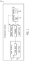
- FIG. 1 is a schematic diagram of an embodiment of an attraction system 50, which may be a roller coaster, a dark ride, a drop tower, or any other suitable attraction system 50.
- the attraction system 50 may have a ride vehicle 52 in which guests may be positioned during operation of the attraction system 50.
- the ride vehicle 52 may have one or more ride seats 54 that guests may occupy within the ride vehicle 52.
- the ride vehicle 52 may be configured to travel along a ride path 56.
- the ride path 56 may be a track that guides the ride vehicle 52 through the attraction system 50, and/or the ride path 56 may include an open surface through which the ride vehicle 52 may generally travel (e.g., the ride vehicle 52 may be guided based on a user input).
- the attraction system 50 may not have the ride path 56. Rather, the ride vehicle 52 may remain stationary within the attraction system 50 during operation, such as for a theatrical show. Indeed, the ride vehicle 52 may alternatively be any suitable guest area of the attraction system 50 in which guests may be situated during operation of the attraction system 50.
- the attraction system 50 may also include show effects 58 that further enhance the experience of the guests.
- the show effects 58 may include lighting, sounds, animated figures, and the like, that provide additional features to entertain the guests.
- the attraction system 50 may also include a guest path 60 that guests may use to navigate through the attraction system 50, such as from an entrance of the attraction system 50 to the ride vehicle 52 and/or from the ride vehicle 52 to an exit of the attraction system 50.
- the guest path 60 may include a footpath (e.g., a queue), a staircase, an escalator, an elevator, and so forth.
- the show effects 58 may entertain the guests as they navigate the guest path 60 in the attraction system 50 such that the guests may also be entertained while waiting within the attraction system 50 (e.g., when not in the ride vehicle 52).
- the attraction system 50 may include and/or be communicatively coupled with a control system 62.
- the control system 62 may include a memory 64 and a processor 66, such as a microprocessor.
- the memory 64 may include volatile memory, such as random access memory (RAM), and/or non-volatile memory, such as read-only memory (ROM), optical drives, hard disc drives, solid-state drives, or any other non-transitory computer-readable medium that includes instructions to operate the attraction system 50, such as the show effects 58.
- RAM random access memory
- ROM read-only memory
- optical drives such as hard disc drives, solid-state drives, or any other non-transitory computer-readable medium that includes instructions to operate the attraction system 50, such as the show effects 58.
- the processor 66 may include one or more application specific integrated circuits (ASICs), one or more field programmable gate arrays (FPGAs), one or more general purpose processors, or any combination thereof, configured to execute the instructions stored in the memory 64 to control the attraction system 50.
- the control system 62 may be configured to receive a user input to operate the attraction system 50.
- the control system 62 may include a user interface with which a user, such as an operator and/or a guest of the attraction system 50, may interact to operate the attraction system 50.
- the control system 62 may automatically operate the attraction system 50 without receiving the user input.
- the control system 62 may be communicatively coupled to one or more sensors 68.
- the sensor(s) 68 may be configured to monitor an operating parameter of the attraction system 50, and the sensor(s) 68 may transmit data (e.g., sensor data) indicative of the operating parameter to the control system 62.
- the sensor(s) 68 may include individual systems of one or more emitters and detectors that operate together to detect objects or portions of objects (e.g., a seat back), including identifying measurements, such as distance to the objects, size of the objects, relative spacing of the objects, and so forth.
- the sensor(s) 68 may include wave-based technology, such as light emitters and detectors that cooperate with a processor to correlate detections with measurements to provide data.
- the control system 62 may then operate the attraction system 50 based on the data.
- the sensor(s) 68 may be configured to monitor an operating parameter associated with occupancy of the ride vehicle 52.
- the sensor(s) 68 may determine whether the guests are occupying the ride seat(s) 54 of the ride vehicle 52.
- the control system 62 therefore operates the attraction system 50 based on the occupancy of the ride vehicle 52.
- the control system 62 may activate certain show effects 58 based on the number of detected guests in the ride vehicle 52.
- the control system 62 may store information (e.g., in the memory 64) associated with the number of detected guests in the ride vehicle 52.
- the control system 62 may monitor the number of guests that go through the attraction system 50 over a period of time. The control system 62 may then store such information, which may be used for determining the popularity of the attraction system 50, a guest capacity over a time of operation, and the like.
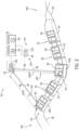
- FIG. 2 is a side perspective view of an embodiment of the attraction system 50.
- the attraction system 50 includes multiple ride vehicles 52 coupled together (e.g., via a link) and configured to travel along the ride path 56.
- the illustrated ride path 56 may be a track that guides the movement (e.g., direction, speed, and/or orientation) of the ride vehicle 52 through the attraction system 50.
- Each ride vehicle 52 also includes one or more ride seats 54 that each may hold one or more guests of the attraction system 50.
- each ride seat 54 may include a restraint 90, such as a lap bar, configured to secure the guests within the ride vehicles 52 as the ride vehicles 52 move along the ride path 56 during operation of the attraction system 50.
- the attraction system 50 may include the control system 62, which may be configured to determine an occupancy of the ride vehicles 52 via a first sensor 92 that is communicatively coupled to the control system 62.
- the first sensor 92 may be located at a first position 94 within the attraction system 50 and may be configured to determine a distance between the ride seats 54 and the first sensor 92.
- the first sensor 92 may be configured to emit output signals 96 away from the first position 94 through the attraction system 50, and the output signals 96 may reflect off any physical object (e.g., the ride vehicles 52) as reflected signals 98 and return toward the first sensor 92.
- the output signals 96 and the reflected signals 98 may be the same signal that travels along a path from the first sensor 92 to the physical object, and then deflected off the physical object to return from the physical object to the first sensor 92.
- the output signal 96 refers to such signal at the portion of the path traveling from the first sensor 92 to the physical object
- the reflected signal 98 refers to the same signal at the portion of the path traveling from the physical object to the first sensor 92.
- the first sensor 92 may receive the reflected signals 98 and transmit data associated with the reflected signals 98 to the control system 62 for further processing.
- the first sensor 92 may be a light detection and ranging (LIDAR) device, a sound navigation ranging (sonar) device, a radio detection and ranging (radar) device, an infrared remote sensing device, another suitable device, or any combination thereof, configured to emit and receive signals 96, 98 between the first sensor 92 and another part of the attraction system 50.
- LIDAR light detection and ranging
- sonar sound navigation ranging
- radar radio detection and ranging
- an infrared remote sensing device another suitable device, or any combination thereof
- the particular device used may be based on the application of the attraction system 50, such as whether certain show effects (e.g., fog, light) may interfere with the signals 96, 98.
- the control system 62 may receive data associated with the output signals 96 and the corresponding reflected signals 98 from the first sensor 92, and the control system 62 may determine a distance between the first sensor 92 and the physical object based on the data.
- the data may include a time associated with receiving one of the reflected signals 98 after emitting a corresponding output signal 96, a wavelength of the reflected signals 98, an angle of the path traveled by the reflected signal 98 to return to the first sensor 92, another suitable parameter associated with the signals 96, 98, or any combination thereof, indicative of a distance of signal travel for the signals 96, 98 between the first sensor 92 and the physical object.
- the control system 62 may determine the distance between the first sensor 92 and the physical object based on the distance of signal travel.
- the first sensor 92 may therefore be used to determine the distance between the first sensor 92 and the ride seats 54 of the ride vehicles 52.
- the first sensor 92 may be positioned such that the output signals 96 may be uninterruptedly emitted (i.e., not blocked by other physical objects of the attraction system 50) to the ride seats 54, and the reflected signals 98 may be uninterruptedly received by the first sensor 92.
- the control system 62 may determine whether the ride vehicles 52 are occupied or unoccupied.
- a distance between an occupied ride seat 54 and the first sensor 92, in which the output signal 96 may fully extend into the ride seat 54 may be greater than a distance between an occupied ride seat 54 and the first sensor 92, in which the output signal 96 may be blocked by a guest before fully extending into the ride seat 54 (i.e., the output signal 96 may merely partially extend into the ride seat 54).
- the control system 62 may determine whether the value of a determined distance between the ride seat 54 and the first sensor 92 matches with a distance corresponding to an unoccupied ride seat 54 or with a distance corresponding to an occupied ride seat 54.
- distances relative to specific areas may be determined to facilitate analysis in accordance with present embodiments. Further, distances relative to restraints (e.g., a lap bar) may also be detected to facilitate determining whether the restraint is properly engaged in addition to the ride seat 54 being occupied.
- the control system 62 may operate the attraction system 50 in a calibration mode to determine baseline distance values associated with unoccupied ride seats 54.
- the control system 62 may operate the ride vehicles 52, such as by moving the ride vehicles 52 along the ride path 56, without any guests positioned within the ride seats 54.
- the first sensor 92 may operate and emit output signals 96 toward the ride vehicles 52 and to the unoccupied ride seats 54 during the calibration mode.
- the control system 62 may receive data associated with the output signals 96 and the resulting reflected signals 98 and, based on the data, the control system 62 may determine an unoccupied distance 100 spans between the unoccupied ride seats 54 and the first sensor 92.
- the unoccupied distance(s) 100 may include detection of the restraint 90 while the ride vehicle 52 is unoccupied. For example, an area of the ride seat 54 that is unobstructed (e.g., with respect to the first sensor 92) by the restraint 90 may be observed to identify a first unoccupied distance 100A and an area where the restraint 90 demonstrates engagement may be monitored to identify a second unoccupied distance 100B. Both distances may be used for calibration and, in combination with subsequent measures, may identify whether a rider is not only present but whether the rider is properly restrained.
- the first sensor 92 may simultaneously emit multiple output signals 96 in various directions, such as toward a first ride vehicle 52A and also toward a second ride vehicle 52B.
- the first ride vehicle 52A which is located in a first part of the attraction system 50 (e.g., at a first section of the ride path 56), may be positioned at a different distance away from the first sensor 92 than that associated with the second ride vehicle 52B, which is located at a second part of the attraction system 50.
- the first sensor 92 may receive respective reflected signals 98 corresponding to the first ride vehicle 52A and the second ride vehicle 52B, and the control system 62 may therefore determine separate unoccupied distances 100 spanning between unoccupied ride seats 54 of different ride vehicles 52 and the first sensor 92.
- control system 62 may determine a first unoccupied distance 100A spans between the unoccupied first ride vehicle 52A and the first sensor 92, and a second unoccupied distance 100B, different from the first unoccupied distance 100A, spans between the unoccupied second ride vehicle 52B and the first sensor 92.
- the control system 62 may associate multiple unoccupied distances 100 with respectively unoccupied ride vehicles 52.
- the first sensor 92 may be configured to emit output signals 96 to a single part of the attraction system 50, such as toward a single point on the ride path 56, in the calibration mode.
- Each ride vehicle 52 traveling along the ride path 56 may intersect with the single point on the ride path 56 at different times and generally, at the single point, each ride vehicle 52 may be positioned at substantially the same distance away from the first sensor 92. Therefore, the data transmitted by the first sensor 92 may be indicative of a single unoccupied distance 100 spanning between the unoccupied ride vehicles 52 and the first sensor 92. Further, the first sensor 92 may emit output signals such that different locations of the same seating area are monitored (e.g., one for occupancy and one for restraint securement). Further, the first sensor 92 may be representative of multiple sensing devices that coordinate to perform such monitoring. In any case, the control system 62 may store the unoccupied distance(s) 100 determined via the calibration mode of the attraction system 50, such as within the memory 64, and the unoccupied distance(s) 100 may be retrieved and/or referenced at a later time.
- the unoccupied distance(s) 100 may be used to determine whether the ride vehicles 52 are occupied.
- the first sensor 92 may continue to emit and receive signals 96, 98 during operation of the attraction system 50, and the control system 62 may constantly receive data to determine the distance between the first sensor 92 and the ride vehicles 52. The control system 62 may then compare the determined distances with the stored unoccupied distance(s) 100 to determine whether the ride vehicles 52 are occupied or unoccupied.
- control system 62 may determine whether the determined distances substantially match with the unoccupied distance(s) 100 to indicate that one of the ride vehicles 52 is unoccupied, or whether the determined distances do not substantially match with (e.g., the determined distances are less than) the unoccupied distance(s) 100 to indicate that one of the ride vehicles 52 is occupied by a guest. As previously discussed, similar operation can be performed for identifying whether restraints (e.g., a lap bar) are properly positioned.
- restraints e.g., a lap bar
- the first sensor 92 may be positioned at any suitable location within the attraction system 50 to enable the signals 96, 98 to be transmitted between the ride seats 54 and the first sensor 92.
- the first sensor 92 may be positioned on the ride vehicle 52, on part of the ride path 56, and the like.
- the first sensor 92 may be fixedly coupled to the first position 94, such as by attaching to a stationary structure (e.g., a support of the ride path 56) within the attraction system 50. As such, the first sensor 92 may substantially remain in the first position 94 during operation of the attraction system 50.
- the first sensor 92 may be configured to move within the attraction system 50.
- the first sensor 92 may be coupled to a device that is movable within the attraction system 50 so as to follow the ride vehicles 52 and/or be guided by a user (e.g., away from physical show effects or features within the attraction system 50) in order to emit and receive signals 96, 98 uninterruptedly. Movement of the first sensor 92 relative to the ride vehicles 52 may change the distances between the first sensor 92 and the ride vehicles 52.
- the ride vehicles 52 may move at elevated speeds and/or complex movements (e.g., corkscrew or twisting) that may cause difficulty for the signals 96, 98 to accurately indicate the distance between the ride vehicles 52 and the first sensor 92.
- the determined distance between one of the unoccupied ride vehicles 52 and the first sensor 92 may not substantially match the stored unoccupied distance 100 because the ride vehicle 52 may be oriented such that the output signals 96 emitted by the first sensor 92 may be transmitted to a side of the ride vehicle 52 instead of to the intended unoccupied ride seat 54.
- the determined distance may not accurately reflect the occupancy of the ride vehicle 52 because of the orientation of the ride vehicle 52 relative to the first sensor 92.
- the attraction system 50 may also include a second sensor 102, which may be rigidly coupled to the first sensor 92 such that a change in positioning of the first sensor 92 may cause a corresponding change in positioning of the second sensor 102.
- positioning includes an orientation, a location, a pose, and/or a position.
- the second sensor 102 may be configured to determine the positioning of the ride vehicle 52 relative to the second sensor 102 and therefore relative to the first sensor 92.
- the second sensor 102 may include an optical camera and/or another image sensing device, and the second sensor 102 may use machine vision to determine the positioning of the ride vehicle 52 relative to the first sensor 92 and vice versa.
- the second sensor 102 may also be communicatively coupled to the control system 62 and may transmit data indicative of the positioning of the ride vehicle 52 relative to the first sensor 92. Based on such data, the control system 62 may modify the unoccupied distance 100 accordingly. By way of example, after the unoccupied distance(s) 100 have been determined and stored in accordance to the first position 94 of the first sensor 92, the second sensor 102 may transmit data to the control system 62 and indicate that a relative distance between the first sensor 92 and the ride vehicle 52 has changed, such as the first sensor 92 moving to a second position 104 (as represented by elements 92 and 102 in dashed lines).
- the control system 62 may then update the stored unoccupied distance(s) 100 accordingly to reflect the location of the first sensor 92 at the second position 104. For instance, the control system 62 may determine that at the second position 104, the first sensor 92 is substantially closer to the ride vehicles 52 than the first sensor 92 was at the first position 94 and therefore, the control system 62 may reduce the unoccupied distance(s) 100. As such, while the first sensor 92 is at the second position 104, the control system 62 may compare subsequently determined distances indicated by the first sensor 92 with the updated reduced unoccupied distance(s) 100 associated with the second position 104, rather than the originally stored unoccupied distance(s) 100 associated with the first position 94, to accurately determine whether the ride vehicles 52 are occupied.
- the control system 62 may then update the unoccupied distance(s) 100 again (e.g., to the originally stored unoccupied distance[s]) and compare distances to the updated unoccupied distance(s) 100.
- the functionality of the first sensor 92 and the second sensor 102 may be provided by a single sensing device. However, the single sensing device may still be referred to as the first sensor 92 and the second sensor 102 based on the separate functionality. Further, in an alternative embodiment, relative positioning of the first sensor 92 and the ride vehicle 52 may be determined by the control system 62 based on models of the ride path 56 and positional data, thereby avoiding the use of additional sensing devices.
- control system 62 may cause the first sensor 92 to emit output signals 96 when the ride vehicles 52 are determined to be within a certain range of the output signals 96, and the control system 62 may cause the first sensor 92 not to emit output signals 96 when the ride vehicles 52 are determined to be out of a certain range of the output signals 96.
- the control system 62 may selectively cause the first sensor 92 to emit output signals 96 at certain times, rather than to constantly emit the output signals 96, thereby reducing an energy consumption associated with operating the first sensor 92.
- the control system 62 may determine a location of the ride vehicles 52 in the attraction system 50.
- the control system 62 may also store multiple locations (e.g., proximate to the first sensor 92) in which the control system 62 may activate the first sensor 92. Thus, in response to determining the ride vehicles 52 are at locations included in the stored locations, the control system 62 may activate the first sensor 92 to emit and receive signals 96, 98. However, upon determining the ride vehicles 52 are not at locations included in the stored locations, the control system 62 may suspend operation of the first sensor 92.
- FIG. 2 discusses operating the attraction system 50 in a calibration mode in which the ride vehicle 52 may travel along an entirety of the ride path 56 without any passengers or guests to obtain unoccupied distances 100
- FIG. 2 may illustrate a portion of the ride path 56 where the ride vehicle 52 is unoccupied during normal operation of the attraction system 50 (i.e., operation of the attraction system 50 to entertain guests).
- the illustrated portion of the ride path 56 is between an unloading area 106, where guests may exit the ride vehicle 52, and before a loading area 108, where guests may enter the ride vehicle 52.
- the ride vehicle 52 may be occupied before the unloading area 106 and also after the loading area 108, but the ride vehicle 52 may be unoccupied after the unloading area 106 and before the loading area 108.
- the first sensor 92 may emit the output signals 96 toward the illustrated portion of the ride path 56 in order to acquire the unoccupied distances 100 without the attraction system 50 having to operate in the calibration mode that is different than normal operation. Accordingly, the unoccupied distances 100 may be acquired without interrupting flow through the attraction system 50 (e.g., by shutting down the attraction system 50 to operate in the calibration mode).
- the first sensor 92 may be configured to direct output signals 96 toward the illustrated portion of the ride path 56 to obtain unoccupied distances 100, and the first sensor 92 may be able to re-orient and/or re-position. Thus, the first sensor 92 may direct the output signals 96 toward a different portion of the ride path 56 where the ride vehicle 52 may be occupied to acquire additional distances (e.g., distances possibly indicating an occupied ride vehicle 52). The additional distances, such as after modification based on the second sensor 102, may then be compared with the unoccupied distances 100 to determine whether the ride vehicle 52 is occupied.
- additional distances e.g., distances possibly indicating an occupied ride vehicle 52
- an additional first sensor 92 may be used to direct output signals 96 to the ride vehicle 52 at a different section of the ride path 56 to acquire the additional distances for comparison with the unoccupied distances 100.
- the unoccupied distances 100 may be obtained in an ongoing manner during normal operation of the attraction system 50.
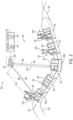
- FIG. 3 is a side perspective view of the attraction system 50 of FIG. 2 in which the ride vehicles 52 of the attraction system 50 are occupied by guests 120.
- the attraction system 50 may be in an operating mode to entertain the guests 120.
- the control system 62 may operate the attraction system 50 in the operating mode after storing the unoccupied distance(s) in the calibration mode.
- the control system 62 instructs the first sensor 92 to emit and receive signals 96, 98 to enable the control system 62 to determine whether the ride vehicles 52 are occupied.
- the first ride vehicle 52A is occupied with the guests 120.
- the data transmitted by the first sensor 92 may indicate that a first distance 122 spanning between the first sensor 92 and the first ride vehicle 52A is less than the stored unoccupied distance, because the output signal 96 may reflect off the guests 120 rather than off the ride seat 54 (e.g., a seating portion or floor portion of the ride seat 54).
- the control system 62 may compare the first distance 122 with the stored unoccupied distance to determine whether the first ride vehicle 52A is occupied. In an example, the control system 62 may determine that the first distance 122 is less than the unoccupied distance 100 of FIG. 2 by greater than a threshold distance. As such, the control system 62 may determine that the first distance 122 indicates the first ride vehicle 52A is occupied.
- the second ride vehicle 52B may not be occupied with guests 120.
- the data transmitted by the first sensor 92 may indicate that a second distance 124 spanning between the first sensor 92 and the first ride vehicle 52A is substantially the same as the stored unoccupied distance. That is, the control system 62 may determine that the second distance 124 does not deviate from the unoccupied distance 100 of FIG. 2 by greater than the threshold distance. Thus, the control system 62 may determine that the second distance 124 indicates the second ride vehicle 52B is unoccupied.
- a single first sensor 92 is implemented within the attraction system 50.
- multiple first sensors 92 may be implemented and used for determining the occupancy of the ride vehicles 52.
- the data received from each of the first sensors 92 may be compared with one another to determine the accuracy in the respectively determined distances between the first sensors 92 and the ride vehicles 52.
- multiple pairs of first sensors 92 and second sensors 102 may be implemented to determine the occupancy of the ride vehicles 52 based on various respective positionings of the first sensors 92 relative to the ride vehicles 52.
- the illustrated attraction system 50 in FIGS. 2 and 3 include a moving ride vehicle 52
- the described approach for determining the occupancy of the attraction system 50 may be implemented for a stationary area in which the guests 120 may occupy.
- the attraction system 50 may be a performance or theatrical show having seats that do not substantially move within the attraction system 50, but the first sensor 92 may still be used for determining the distance between the first sensors 92 and the seats.
- FIGS. 4 and 5 illustrate respective embodiments of a method or process for operating an attraction system, such as the attraction system 50 of FIGS. 2 and 3 .
- the steps of each method may be performed by a single controller, such as the control system 62 ( FIGS. 1-3 ), or multiple controllers may perform different steps of each method. It should also be noted that the steps of each method may be performed differently in another embodiment, such as for a different embodiment of the attraction system. For example, additional steps may be performed, or certain steps of each method may be modified, removed, or performed in a different order.
- FIG. 4 is a flowchart of an embodiment of a method or process 150 for operating an attraction system to determine an unoccupied distance value.
- the attraction system is operated in a calibration mode.
- unoccupied ride vehicles of the attraction system may be in operation to travel through the attraction system (e.g., via a ride path). This may be a segment of normal operation, which may assist with limiting measurement discrepancies and continual throughput for the attraction.
- an unoccupied distance value is determined during the calibration mode.
- the first sensor is instructed to emit output calibration signals toward the unoccupied ride vehicle and to receive corresponding reflected calibration signals.
- the first sensor may transmit calibration data that is based on the output calibration signals and reflected calibration signals.
- a resulting calibration distance between the first sensor and the unoccupied ride vehicle e.g., a seat, a specific portion of a seat, a restraint in a desired position while the seat is unoccupied
- multiple calibration distances may be determined for respective ride vehicles positioned at different locations within the attraction system. Additionally or alternatively, a single calibration distance may be determined and associated with all of the ride vehicles.
- the calibration distance determined via the calibration mode is stored as the unoccupied distance value, as indicated at block 156.
- the frequency in which the steps of the method 150 are performed may vary based on the attraction system.
- the method 150 may be performed once per day such that accurate unoccupied distance value(s) are determined and updated every day.
- the method 150 may be performed once every time the attraction system is modified, such as after the ride vehicles (e.g., the ride seats) are modified and/or after show elements are changed.
- the method 150 may be performed at a suitable frequency to update and store accurate unoccupied distance value(s).
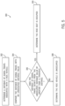
- FIG. 5 is a flowchart of an embodiment of a method or process 180 for determining the occupancy of a ride vehicle.
- the method 180 may be performed during the operating mode of the attraction system and is performed after the method 150, such that a corresponding unoccupied distance value has been determined and is retrievable.
- a distance of signal travel is determined.
- the distance of signal travel may indicate a current distance between the first sensor and the ride vehicle (e.g., a seat, a specific portion of a seat, a restraint in a desired position while the seat is unoccupied).
- the first sensor may be instructed to emit output signals toward the ride vehicle and receive corresponding reflected signals, and the distance of signal travel may be determined based on a parameter of the reflected signals.
- the sensor may then transmit data indicative of the distance of signal travel.
- the distance of signal travel is compared with the unoccupied distance value, which may have been determined via the calibration mode.
- the unoccupied distance value may be updated or modified based on a determined positioning of the first sensor relative to the ride vehicle. That is, the unoccupied distance value determined and stored via the calibration mode may be applicable at a first positioning of the first sensor relative to the ride vehicle. However, the first sensor may currently be at a second positioning relative to the ride vehicle (e.g., the first sensor was moved within the attraction system). Therefore, the initially determined unoccupied distance value may be updated to reflect the second positioning, and the updated unoccupied distance value may accurately reflect a distance between the unoccupied ride vehicle and the first sensor based on the second positioning.
- a calibration distance may be supplied to multiple sensors (e.g., the first sensor 92) throughout the ride path 56 and adjustments to the calibration distance may be made based on a model or known relative orientations of each sensor to the ride vehicle 52 when within monitoring range of the particular sensor.
- the current distance between an occupied ride vehicle and the first sensor may be substantially less than the calibration distance between an unoccupied ride vehicle and the first sensor.
- the determination may be made as to whether the distance of signal travel is substantially less than the unoccupied distance value (e.g., by an amount that is greater than the threshold distance).
- the threshold distance may be set based on a database of body metrics for standard body sizes and body characteristics. For example, a 15.24 centimeters (six inch) threshold may be set based on a minimum human body thickness that would be positioned at the monitored location of a seat.
- the distance of signal travel may be less than the unoccupied distance value by an amount greater than the threshold distance and therefore, the distance of signal travel indicates that the ride vehicle is occupied.
- further actions may be performed based on the comparison between the distance of signal travel with the unoccupied distance value.
- information regarding the occupancy of the ride vehicle may be stored. Such information may then be referenced at a later time to determine information regarding the attraction system. For example, the occupancy of the ride vehicle may be used to determine whether the attraction system is to be modified (e.g., to increase popularity of the attraction system).
- operation of the attraction system may be modified. For instance, the operation of the attraction system may be suspended or terminated.
- the ride path taken by one of the ride vehicles may be modified based on the occupancy of the ride vehicle. That is, the ride vehicle may be configured to travel in a variety of manners through the attraction system, and a particular ride path may be selected based on the determined occupancy.
- additional information regarding the occupancy of the ride vehicle may be determined.
- further distances may be determined and stored in addition to the unoccupied distance value associated with an unoccupied ride vehicle.
- Such distances may include a first distance indicative that another object (e.g., a jacket, a bag) is in the ride vehicle without a guest.
- the object may be smaller than a typical guest such that the first distance does not deviate from the unoccupied distance value by greater than the threshold distance, but may still substantially deviate from the unoccupied distance value.
- Other stored distances may include a first set of distances that are indicative of the position of the guests.
- the first set of distances may indicate postures of the guest, such as a second distance indicative of a seated guest, a third distance indicative of a standing guest, a fourth distance indicative of a leaned over guest, and the like.
- the first set of distances may indicate how the guests are positioned relative to the ride vehicle, such as whether the guests are fully contained within the ride seat, whether part of the guest is not contained within the ride seat, whether multiple guests are positioned in a single ride seat (e.g., a child on a parent's lap), whether guests are moving within the ride seat (e.g., not fully secured within the ride seat), and so forth. Such information may then be used for determining improvements for securing guests within the ride vehicles.
- the stored distances may further include a second set of distances indicative of an attribute of the guests.
- the second set of distances may indicate a height and/or a torso size of the guests. In this way, certain parameters or demographics of the guests, such as age, may be determined, and additional information regarding the occupancy of the attraction system may be used for improving the attraction system.
- certain distances such as an excessive distance that deviates from the unoccupied distance value by a substantial amount greater than the threshold distance (e.g., by an additional threshold distance greater than the threshold distance) may indicate that operation of a component (e.g., of the ride vehicle, of the first sensor, of the control system) in the attraction system is to be modified, such as for performing maintenance.
- a notification may be output upon determination of the excessive distance to inform a user, such as an operator of the attraction system, of such information.
- the notification may include a visual output (e.g., a light), an audio output, a notification sent to a mobile device, another suitable notification, or any combination thereof.
- the calibration mode may include determining and storing occupied distance(s) associated with occupied ride vehicles.
- fully occupied ride vehicles e.g., occupied by the guests or by objects representative of guests
- the control system may determine the occupied distance(s) between the ride vehicles and the first sensor.
- the occupied distance(s) may then be stored and may be used for comparing distances determined during the operating mode of the attraction system in order to determine the occupancy of the ride vehicles.
- a determination may be made that the ride vehicle is occupied, and if the determined distance substantially deviate from the stored occupied distance(s), a determination may be made that the ride vehicle is unoccupied.
Landscapes
- Engineering & Computer Science (AREA)
- Physics & Mathematics (AREA)
- Radar, Positioning & Navigation (AREA)
- Remote Sensing (AREA)
- Electromagnetism (AREA)
- Computer Networks & Wireless Communication (AREA)
- General Physics & Mathematics (AREA)
- Mechanical Engineering (AREA)
- Train Traffic Observation, Control, And Security (AREA)
- Seats For Vehicles (AREA)
- Air Bags (AREA)
- Radar Systems Or Details Thereof (AREA)
Claims (15)
- Ein Attraktionssystem (50), umfassend:einen Sensor (68, 92), der dazu konfiguriert ist, ein Ausgabesignal (96) an ein Fahrgeschäftsfahrzeug des Attraktionssystems zu emittieren und ein reflektiertes Signal (98) von dem Fahrgeschäftsfahrzeug (52) zu empfangen; undein Steuerungssystem (62), das mit dem Sensor (68, 92) kommunikativ gekoppelt ist, wobei das Steuerungssystem (62) zu Folgendem konfiguriert ist:Empfangen von Daten von dem Sensor (68, 92), wobei die Daten eine Distanz eines Signallaufs basierend auf dem Ausgabesignal (96) und dem reflektierten Signal (98) angeben;Vergleichen der Distanz des Signallaufs mit einem Wert für eine unbesetzte Distanz, der einer Distanz zwischen dem Sensor (68, 92) und dem Fahrgeschäftsfahrzeug (52) entspricht, die unbesetzt ist; undBestimmen, ob das Fahrgeschäftsfahrzeug (52) besetzt ist, basierend auf dem Vergleichen einer Differenz zwischen der Distanz des Signallaufs und dem Wert für die unbesetzte Distanz mit einer Schwelle.
- Attraktionssystem (50) nach Anspruch 1, wobei das Steuerungssystem (62) dazu konfiguriert ist, als Reaktion auf das Bestimmen, dass die Differenz die Schwelle überschreitet, zu bestimmen, dass das Fahrgeschäftsfahrzeug besetzt ist, wobei die Schwelle einem Distanzwert für eine Körpermetrik entspricht, die mit einem bestimmten Abschnitt des Fahrgeschäftsfahrzeugs (52) assoziiert ist, für den der Sensor (68, 92) dazu konfiguriert ist, das Ausgabesignal (96) an diesen zu emittieren.
- Attraktionssystem (50) nach Anspruch 1, wobei das Steuerungssystem (62) dazu konfiguriert ist, als Reaktion auf das Bestimmen, dass die Differenz die Schwelle nicht überschreitet, zu bestimmen, dass das Fahrgeschäftsfahrzeug unbesetzt ist.
- Attraktionssystem (50) nach Anspruch 1, wobei das Steuerungssystem (62) dazu konfiguriert ist, das Attraktionssystem (50) in einem Kalibrierungsmodus zu betreiben, während das Fahrgeschäftsfahrzeug (52) ein unbesetztes Fahrgeschäftsfahrzeug ist, wobei das Steuerungssystem (62) im Kalibrierungsmodus zu Folgendem konfiguriert ist:Anweisen des Sensors (68, 92) oder eines separaten Sensors, Ausgabekalibrierungssignale an das unbesetzte Fahrgeschäftsfahrzeug zu emittieren und reflektierte Kalibrierungssignale von dem unbesetzten Fahrgeschäftsfahrzeug zu empfangen;Empfangen von Kalibrierungsdaten von dem Sensor (68, 92) oder dem separaten Sensor, wobei die Kalibrierungsdaten auf den Ausgabekalibrierungssignalen und den reflektierten Kalibrierungssignalen basieren;Bestimmen einer Kalibrierungsdistanz, die mit den Kalibrierungsdaten assoziiert ist; undSpeichern der Kalibrierungsdistanz als Wert für die unbesetzte Distanz.
- Attraktionssystem (50) nach Anspruch 1, wobei das Fahrgeschäftsfahrzeug (52) ein unbesetztes Fahrgeschäftsfahrzeug zwischen einem Ausladebereich und einem Ladebereich ist, und das Steuerungssystem (62) zu Folgendem konfiguriert ist:Anweisen des Sensors (68, 92) oder eines separaten Sensors, Ausgabekalibrierungssignale an das unbesetzte Fahrgeschäftsfahrzeug zu emittieren und reflektierte Kalibrierungssignale von dem unbesetzten Fahrgeschäftsfahrzeug zu empfangen;Empfangen von Kalibrierungsdaten von dem Sensor (68, 92) oder dem separaten Sensor, wobei die Kalibrierungsdaten auf den Ausgabekalibrierungssignalen und den reflektierten Kalibrierungssignalen basieren;Bestimmen einer Kalibrierungsdistanz, die mit den Kalibrierungsdaten assoziiert ist; undSpeichern der Kalibrierungsdistanz als Wert für die unbesetzte Distanz.
- Attraktionssystem (50) nach Anspruch 1, wobei der Sensor ein erster Sensor (92) ist, die Daten erste Daten sind, das Attraktionssystem (50) einen zweiten Sensor (102) umfasst, der dazu konfiguriert ist, eine Positionierung des ersten Sensors (92) relativ zu dem Fahrgeschäftsfahrzeug zu bestimmen, wobei der zweite Sensor (102) mit dem Steuerungssystem kommunikativ gekoppelt ist und der zweite Sensor (102) dazu konfiguriert ist, zweite Daten zu übertragen, die eine aktualisierte Positionierung des ersten Sensors (92) relativ zu dem Fahrgeschäftsfahrzeug angeben.
- Attraktionssystem (50) nach Anspruch 6, wobei das Steuerungssystem (62) zu Folgendem konfiguriert ist:Einstellen des Wertes für die unbesetzte Distanz auf einen aktualisierten Wert für die unbesetzte Distanz basierend auf den zweiten Daten, die die aktualisierte Positionierung des ersten Sensors (92) relativ zu dem Fahrgeschäftsfahrzeug angeben;Empfangen von dritten Daten von dem ersten Sensor (92), wobei die dritten Daten eine zusätzliche Distanz des Signallaufs basierend auf einem zweiten Ausgabesignal von dem ersten Sensor (92) und einem zweiten reflektierten Signal, das von dem ersten Sensor (92) detektiert wird, angeben, während sich der erste Sensor (92) in der aktualisierten Positionierung relativ zu dem Fahrgeschäftsfahrzeug befindet;Vergleichen der zusätzlichen Distanz des Signallaufs mit dem aktualisierten Wert für die unbesetzte Distanz; undBestimmen, ob das Fahrgeschäftsfahrzeug besetzt ist, basierend auf dem Vergleich zwischen der zusätzlichen Distanz des Signallaufs und dem aktualisierten Wert für die unbesetzte Distanz.
- Attraktionssystem (50) nach Anspruch 1,
wobei das Fahrgeschäftsfahrzeug dazu konfiguriert ist, entlang eines Fahrgeschäftswegs des Attraktionssystems zu laufen. - Attraktionssystem (50) nach Anspruch 8, wobei das Steuerungssystem (62) dazu konfiguriert ist, als Reaktion auf die Bestimmung, dass die Distanz um einen Betrag kleiner als die unbesetzte Distanz ist, der eine Schwellendistanz überschreitet, zu bestimmen, dass das Fahrgeschäftsfahrzeug (52) besetzt ist, wobei das Steuerungssystem (62) dazu konfiguriert ist, basierend auf dem Ausgabesignal (96) und dem reflektierten Signal (98) eine Position eines Gastes (120) in dem Fahrgeschäftsfahrzeug (52), eine Größe des Gastes (120) in dem Fahrgeschäftsfahrzeug (52) oder beides zu bestimmen.
- Attraktionssystem (50) nach Anspruch 8, wobei der Sensor (68, 92) nicht mit dem Fahrgeschäftsfahrzeug (52) gekoppelt ist.
- Attraktionssystem (50) nach Anspruch 8, wobei das Steuerungssystem (62) dazu konfiguriert ist, basierend auf dem Ausgabesignal (96) und dem reflektierten Signal (98) zu bestimmen, ob eine Halteeinrichtung eingerastet ist.
- Ein nicht transitorisches, computerlesbares Medium (64), das ausführbare Anweisungen umfasst, wobei die Anweisungen, wenn sie durch einen Prozessor (66) ausgeführt werden, dazu konfiguriert sind, den Prozessor (66) zu Folgendem zu veranlassen:Betreiben eines Attraktionssystems (50) in einem Kalibrierungsmodus, um eine unbesetzte Distanz zu bestimmen, die zwischen einem Sensor (68, 92) des Attraktionssystems (50) und einem Fahrgeschäftsfahrzeug (52) des Attraktionssystems (50) liegt, wenn das Fahrgeschäftsfahrzeug (52) unbesetzt ist;Betreiben des Attraktionssystems (50) in einem Betriebsmodus, um eine aktuelle Distanz zu bestimmen, die zwischen dem Sensor (68, 92) oder einem separaten Sensor und dem Fahrgeschäftsfahrzeug liegt;Vergleichen der aktuellen Distanz mit der unbesetzten Distanz; undBestimmen, ob das Fahrgeschäftsfahrzeug (52) im Betriebsmodus des Attraktionssystems (50) besetzt ist, basierend auf dem Vergleich zwischen der aktuellen Distanz und der unbesetzten Distanz.
- Nicht transitorisches computerlesbares Medium (64) nach Anspruch 12, wobei die Anweisungen, wenn sie durch den Prozessor (66) ausgeführt werden, dazu konfiguriert sind, den Prozessor (66) zu Folgendem zu veranlassen:Anweisen des Sensors (68, 92), ein Ausgabekalibrierungssignal an das Fahrgeschäftsfahrzeug zu emittieren und ein entsprechendes reflektiertes Kalibrierungssignal zu empfangen;Empfangen von Daten, die mit dem Ausgabekalibrierungssignal und dem entsprechenden reflektierten Kalibrierungssignal assoziiert sind, von dem Sensor (68, 92); undBestimmen und Speichern der unbesetzten Distanz basierend auf den Daten, die von dem Sensor (68, 92) empfangen werden.
- Nicht transitorisches computerlesbares Medium (64) nach Anspruch 12, wobei die Anweisungen, wenn sie durch den Prozessor (66) ausgeführt werden, dazu konfiguriert sind, den Prozessor (66) zu Folgendem zu veranlassen:Veranlassen des separaten Sensors, ein Ausgabesignal an das Fahrgeschäftsfahrzeug zu emittieren und ein entsprechendes reflektiertes Signal zu empfangen;Empfangen von Daten, die mit dem Ausgabesignal und dem entsprechenden reflektierten Signal assoziiert sind, von dem separaten Sensor; undBestimmen der aktuellen Distanz basierend auf den Daten, die von dem separaten Sensor empfangen werden.
- Nicht transitorisches computerlesbares Medium (64) nach Anspruch 12, wobei die Anweisungen, wenn sie durch den Prozessor ausgeführt werden, dazu konfiguriert sind, den Prozessor zu Folgendem zu veranlassen:Empfangen von zusätzlichen Daten, die mit einer aktualisierten Positionierung des Sensors (68, 92) relativ zu dem Fahrgeschäftsfahrzeug assoziiert sind;Einstellen der unbesetzten Distanz auf eine aktualisierte unbesetzte Distanz basierend auf den zusätzlichen Daten;Bestimmen einer anschließenden aktuellen Distanz, die zwischen dem Sensor (68, 92) und dem Fahrgeschäftsfahrzeug liegt, wenn sich der Sensor (68, 92) in der aktualisierten Positionierung relativ zu dem Fahrgeschäftsfahrzeug befindet;Vergleichen der anschließenden Distanz mit der aktualisierten unbesetzten Distanz; undBestimmen, ob das Fahrgeschäftsfahrzeug besetzt ist, basierend auf dem Vergleich zwischen der anschließenden aktuellen Distanz und der aktualisierten unbesetzten Distanz.
Applications Claiming Priority (3)
| Application Number | Priority Date | Filing Date | Title |
|---|---|---|---|
| US202062984092P | 2020-03-02 | 2020-03-02 | |
| US16/827,113 US11420578B2 (en) | 2020-03-02 | 2020-03-23 | Rider monitoring using depth sensor |
| PCT/US2021/020310 WO2021178316A1 (en) | 2020-03-02 | 2021-03-01 | Rider monitoring using depth sensor |
Publications (2)
| Publication Number | Publication Date |
|---|---|
| EP4114542A1 EP4114542A1 (de) | 2023-01-11 |
| EP4114542B1 true EP4114542B1 (de) | 2024-10-16 |
Family
ID=77462772
Family Applications (1)
| Application Number | Title | Priority Date | Filing Date |
|---|---|---|---|
| EP21713542.5A Active EP4114542B1 (de) | 2020-03-02 | 2021-03-01 | Fahrerüberwachung mit tiefensensor |
Country Status (8)
| Country | Link |
|---|---|
| US (1) | US11420578B2 (de) |
| EP (1) | EP4114542B1 (de) |
| JP (1) | JP2023516399A (de) |
| KR (1) | KR20220148874A (de) |
| CN (1) | CN115151320A (de) |
| CA (1) | CA3168320A1 (de) |
| ES (1) | ES2996838T3 (de) |
| WO (1) | WO2021178316A1 (de) |
Families Citing this family (4)
| Publication number | Priority date | Publication date | Assignee | Title |
|---|---|---|---|---|
| WO2023220310A1 (en) * | 2022-05-11 | 2023-11-16 | Universal City Studios Llc | Guest-specific artificial intelligence entity systems and methods |
| KR20250047771A (ko) * | 2022-08-03 | 2025-04-04 | 유니버셜 시티 스튜디오스 엘엘씨 | 놀이공원 시스템을 동작시키는 시스템 및 방법 |
| US20240042341A1 (en) * | 2022-08-03 | 2024-02-08 | Universal City Studios Llc | Systems and methods for operating an amusement park system |
| US12458898B2 (en) * | 2022-09-12 | 2025-11-04 | Universal City Studios Llc | Attraction control system and method using multilayer perceptron neural networks and machine learning |
Family Cites Families (20)
| Publication number | Priority date | Publication date | Assignee | Title |
|---|---|---|---|---|
| US6507779B2 (en) | 1995-06-07 | 2003-01-14 | Automotive Technologies International, Inc. | Vehicle rear seat monitor |
| DE4005598C2 (de) | 1990-02-22 | 2000-06-15 | Bosch Gmbh Robert | Schutzverfahren für Fahrzeuginsassen und Einrichtung zur Durchführung des Verfahrens |
| US5330226A (en) * | 1992-12-04 | 1994-07-19 | Trw Vehicle Safety Systems Inc. | Method and apparatus for detecting an out of position occupant |
| JPH08169289A (ja) * | 1994-12-20 | 1996-07-02 | Mitsubishi Electric Corp | 乗員監視装置、エアバッグ装置、及び車両用制御装置 |
| US5785347A (en) * | 1996-10-21 | 1998-07-28 | Siemens Automotive Corporation | Occupant sensing and crash behavior system |
| US6007095A (en) | 1997-02-05 | 1999-12-28 | Automotive Systems Laboratory, Inc. | Vehicle occupant position sensor |
| US6116640A (en) * | 1997-04-01 | 2000-09-12 | Fuji Electric Co., Ltd. | Apparatus for detecting occupant's posture |
| JP3826245B2 (ja) * | 1997-04-01 | 2006-09-27 | 富士電機デバイステクノロジー株式会社 | 乗員の姿勢判別装置 |
| US6302438B1 (en) | 1998-04-21 | 2001-10-16 | Automotive Systems Laboratory, Inc. | Occupant detection system |
| EP1461583A4 (de) * | 2001-12-04 | 2007-06-06 | Walt Disney Parks And Resorts | Höhenmessverfahren und -vorrichtung |
| US8152648B2 (en) | 2008-05-06 | 2012-04-10 | S2O Design and Engineering | Whitewater terrain park systems |
| EP3003789B1 (de) | 2013-06-04 | 2018-08-01 | Antonio Zamperla S.p.A. | Insassenrückhaltevorrichtung für fahrgeschäfte |
| US10207193B2 (en) | 2014-05-21 | 2019-02-19 | Universal City Studios Llc | Optical tracking system for automation of amusement park elements |
| US9600999B2 (en) * | 2014-05-21 | 2017-03-21 | Universal City Studios Llc | Amusement park element tracking system |
| KR20180016820A (ko) * | 2016-08-08 | 2018-02-20 | 엘지전자 주식회사 | 재실 감지 장치 및 그 제어 방법 |
| US10814817B2 (en) | 2017-06-15 | 2020-10-27 | Ford Global Technologies, Llc | Occupant position detection |
| US10614271B2 (en) | 2018-01-15 | 2020-04-07 | Universal City Studios Llc | Interactive systems and methods |
| JP7369718B2 (ja) | 2018-05-09 | 2023-10-26 | ユニバーサル シティ スタジオズ リミテッド ライアビリティ カンパニー | 遊園地会場における効率的な配席のためのシステム及び方法 |
| US10727960B2 (en) * | 2018-06-08 | 2020-07-28 | Inscape Data, Inc. | System and methods of detecting human presence in the vicinity of a radio frequency receiver system |
| US11025900B2 (en) | 2018-07-18 | 2021-06-01 | Universal City Studios Llc | System and method for identifying b-roll conditions in live streams or live rendered content |
-
2020
- 2020-03-23 US US16/827,113 patent/US11420578B2/en active Active
-
2021
- 2021-03-01 CN CN202180018597.0A patent/CN115151320A/zh active Pending
- 2021-03-01 JP JP2022552875A patent/JP2023516399A/ja active Pending
- 2021-03-01 CA CA3168320A patent/CA3168320A1/en active Pending
- 2021-03-01 EP EP21713542.5A patent/EP4114542B1/de active Active
- 2021-03-01 ES ES21713542T patent/ES2996838T3/es active Active
- 2021-03-01 KR KR1020227033925A patent/KR20220148874A/ko active Pending
- 2021-03-01 WO PCT/US2021/020310 patent/WO2021178316A1/en not_active Ceased
Also Published As
| Publication number | Publication date |
|---|---|
| CA3168320A1 (en) | 2021-09-10 |
| JP2023516399A (ja) | 2023-04-19 |
| CN115151320A (zh) | 2022-10-04 |
| US20210268984A1 (en) | 2021-09-02 |
| KR20220148874A (ko) | 2022-11-07 |
| US11420578B2 (en) | 2022-08-23 |
| WO2021178316A1 (en) | 2021-09-10 |
| ES2996838T3 (en) | 2025-02-13 |
| EP4114542A1 (de) | 2023-01-11 |
Similar Documents
| Publication | Publication Date | Title |
|---|---|---|
| EP4114542B1 (de) | Fahrerüberwachung mit tiefensensor | |
| CN111488860B (zh) | 游乐园元件跟踪系统 | |
| JP3819292B2 (ja) | 人物状態判別装置 | |
| JP2003194528A5 (de) | ||
| US20150055678A1 (en) | Information acquisition device for object to be measured | |
| EP3639106A1 (de) | Automatisch geführtes fahrzeugführungssystem (agv) | |
| CN113950362A (zh) | 编排的乘坐系统和方法 | |
| CN113423625A (zh) | 车辆 | |
| HK40082406A (en) | Rider monitoring using depth sensor | |
| CN113269017B (zh) | 识别装置、识别系统、识别方法及存储介质 | |
| KR20240132084A (ko) | 어트랙션 시스템을 위한 이미지 제공 시스템 및 방법 | |
| EP4132671B1 (de) | Erfassungssystem für ein interaktives system | |
| KR20200133850A (ko) | 자율 주행 장치 및 방법 | |
| KR20250039741A (ko) | 하차 보조 기능 및 이를 포함하는 시트 장치 | |
| JP2024521751A (ja) | モーションベースアトラクションの後方乗り込みスタイル座席 | |
| HK40034621B (zh) | 游乐园元件跟踪系统 | |
| HK40034621A (en) | Amusement park element tracking system | |
| HK1239906A1 (en) | Amusement park element tracking system | |
| HK1239906B (en) | Amusement park element tracking system |
Legal Events
| Date | Code | Title | Description |
|---|---|---|---|
| STAA | Information on the status of an ep patent application or granted ep patent |
Free format text: STATUS: UNKNOWN |
|
| STAA | Information on the status of an ep patent application or granted ep patent |
Free format text: STATUS: THE INTERNATIONAL PUBLICATION HAS BEEN MADE |
|
| PUAI | Public reference made under article 153(3) epc to a published international application that has entered the european phase |
Free format text: ORIGINAL CODE: 0009012 |
|
| STAA | Information on the status of an ep patent application or granted ep patent |
Free format text: STATUS: REQUEST FOR EXAMINATION WAS MADE |
|
| 17P | Request for examination filed |
Effective date: 20220922 |
|
| AK | Designated contracting states |
Kind code of ref document: A1 Designated state(s): AL AT BE BG CH CY CZ DE DK EE ES FI FR GB GR HR HU IE IS IT LI LT LU LV MC MK MT NL NO PL PT RO RS SE SI SK SM TR |
|
| DAV | Request for validation of the european patent (deleted) | ||
| DAX | Request for extension of the european patent (deleted) | ||
| GRAP | Despatch of communication of intention to grant a patent |
Free format text: ORIGINAL CODE: EPIDOSNIGR1 |
|
| STAA | Information on the status of an ep patent application or granted ep patent |
Free format text: STATUS: GRANT OF PATENT IS INTENDED |
|
| INTG | Intention to grant announced |
Effective date: 20240116 |
|
| GRAJ | Information related to disapproval of communication of intention to grant by the applicant or resumption of examination proceedings by the epo deleted |
Free format text: ORIGINAL CODE: EPIDOSDIGR1 |
|
| STAA | Information on the status of an ep patent application or granted ep patent |
Free format text: STATUS: REQUEST FOR EXAMINATION WAS MADE |
|
| GRAP | Despatch of communication of intention to grant a patent |
Free format text: ORIGINAL CODE: EPIDOSNIGR1 |
|
| STAA | Information on the status of an ep patent application or granted ep patent |
Free format text: STATUS: GRANT OF PATENT IS INTENDED |
|
| INTC | Intention to grant announced (deleted) | ||
| INTG | Intention to grant announced |
Effective date: 20240531 |
|
| GRAS | Grant fee paid |
Free format text: ORIGINAL CODE: EPIDOSNIGR3 |
|
| GRAA | (expected) grant |
Free format text: ORIGINAL CODE: 0009210 |
|
| STAA | Information on the status of an ep patent application or granted ep patent |
Free format text: STATUS: THE PATENT HAS BEEN GRANTED |
|
| AK | Designated contracting states |
Kind code of ref document: B1 Designated state(s): AL AT BE BG CH CY CZ DE DK EE ES FI FR GB GR HR HU IE IS IT LI LT LU LV MC MK MT NL NO PL PT RO RS SE SI SK SM TR |
|
| REG | Reference to a national code |
Ref country code: GB Ref legal event code: FG4D |
|
| REG | Reference to a national code |
Ref country code: CH Ref legal event code: EP |
|
| REG | Reference to a national code |
Ref country code: IE Ref legal event code: FG4D |
|
| REG | Reference to a national code |
Ref country code: DE Ref legal event code: R096 Ref document number: 602021020345 Country of ref document: DE |
|
| P01 | Opt-out of the competence of the unified patent court (upc) registered |
Free format text: CASE NUMBER: APP_56644/2024 Effective date: 20241017 |
|
| REG | Reference to a national code |
Ref country code: LT Ref legal event code: MG9D |
|
| REG | Reference to a national code |
Ref country code: ES Ref legal event code: FG2A Ref document number: 2996838 Country of ref document: ES Kind code of ref document: T3 Effective date: 20250213 |
|
| REG | Reference to a national code |
Ref country code: NL Ref legal event code: MP Effective date: 20241016 |
|
| PG25 | Lapsed in a contracting state [announced via postgrant information from national office to epo] |
Ref country code: NL Free format text: LAPSE BECAUSE OF FAILURE TO SUBMIT A TRANSLATION OF THE DESCRIPTION OR TO PAY THE FEE WITHIN THE PRESCRIBED TIME-LIMIT Effective date: 20241016 |
|
| PG25 | Lapsed in a contracting state [announced via postgrant information from national office to epo] |
Ref country code: NL Free format text: LAPSE BECAUSE OF FAILURE TO SUBMIT A TRANSLATION OF THE DESCRIPTION OR TO PAY THE FEE WITHIN THE PRESCRIBED TIME-LIMIT Effective date: 20241016 |
|
| PG25 | Lapsed in a contracting state [announced via postgrant information from national office to epo] |
Ref country code: IS Free format text: LAPSE BECAUSE OF FAILURE TO SUBMIT A TRANSLATION OF THE DESCRIPTION OR TO PAY THE FEE WITHIN THE PRESCRIBED TIME-LIMIT Effective date: 20250216 Ref country code: HR Free format text: LAPSE BECAUSE OF FAILURE TO SUBMIT A TRANSLATION OF THE DESCRIPTION OR TO PAY THE FEE WITHIN THE PRESCRIBED TIME-LIMIT Effective date: 20241016 Ref country code: PT Free format text: LAPSE BECAUSE OF FAILURE TO SUBMIT A TRANSLATION OF THE DESCRIPTION OR TO PAY THE FEE WITHIN THE PRESCRIBED TIME-LIMIT Effective date: 20250217 |
|
| PGFP | Annual fee paid to national office [announced via postgrant information from national office to epo] |
Ref country code: DE Payment date: 20250327 Year of fee payment: 5 |
|
| PG25 | Lapsed in a contracting state [announced via postgrant information from national office to epo] |
Ref country code: FI Free format text: LAPSE BECAUSE OF FAILURE TO SUBMIT A TRANSLATION OF THE DESCRIPTION OR TO PAY THE FEE WITHIN THE PRESCRIBED TIME-LIMIT Effective date: 20241016 |
|
| PG25 | Lapsed in a contracting state [announced via postgrant information from national office to epo] |
Ref country code: BG Free format text: LAPSE BECAUSE OF FAILURE TO SUBMIT A TRANSLATION OF THE DESCRIPTION OR TO PAY THE FEE WITHIN THE PRESCRIBED TIME-LIMIT Effective date: 20241016 |
|
| PG25 | Lapsed in a contracting state [announced via postgrant information from national office to epo] |
Ref country code: NO Free format text: LAPSE BECAUSE OF FAILURE TO SUBMIT A TRANSLATION OF THE DESCRIPTION OR TO PAY THE FEE WITHIN THE PRESCRIBED TIME-LIMIT Effective date: 20250116 |
|
| PG25 | Lapsed in a contracting state [announced via postgrant information from national office to epo] |
Ref country code: GR Free format text: LAPSE BECAUSE OF FAILURE TO SUBMIT A TRANSLATION OF THE DESCRIPTION OR TO PAY THE FEE WITHIN THE PRESCRIBED TIME-LIMIT Effective date: 20250117 Ref country code: LV Free format text: LAPSE BECAUSE OF FAILURE TO SUBMIT A TRANSLATION OF THE DESCRIPTION OR TO PAY THE FEE WITHIN THE PRESCRIBED TIME-LIMIT Effective date: 20241016 |
|
| PGFP | Annual fee paid to national office [announced via postgrant information from national office to epo] |
Ref country code: AT Payment date: 20250417 Year of fee payment: 5 |
|
| PG25 | Lapsed in a contracting state [announced via postgrant information from national office to epo] |
Ref country code: PL Free format text: LAPSE BECAUSE OF FAILURE TO SUBMIT A TRANSLATION OF THE DESCRIPTION OR TO PAY THE FEE WITHIN THE PRESCRIBED TIME-LIMIT Effective date: 20241016 |
|
| PGFP | Annual fee paid to national office [announced via postgrant information from national office to epo] |
Ref country code: FR Payment date: 20250325 Year of fee payment: 5 |
|
| PGFP | Annual fee paid to national office [announced via postgrant information from national office to epo] |
Ref country code: IT Payment date: 20250319 Year of fee payment: 5 Ref country code: GB Payment date: 20250327 Year of fee payment: 5 |
|
| PG25 | Lapsed in a contracting state [announced via postgrant information from national office to epo] |
Ref country code: RS Free format text: LAPSE BECAUSE OF FAILURE TO SUBMIT A TRANSLATION OF THE DESCRIPTION OR TO PAY THE FEE WITHIN THE PRESCRIBED TIME-LIMIT Effective date: 20250116 |
|
| PG25 | Lapsed in a contracting state [announced via postgrant information from national office to epo] |
Ref country code: SM Free format text: LAPSE BECAUSE OF FAILURE TO SUBMIT A TRANSLATION OF THE DESCRIPTION OR TO PAY THE FEE WITHIN THE PRESCRIBED TIME-LIMIT Effective date: 20241016 |
|
| PG25 | Lapsed in a contracting state [announced via postgrant information from national office to epo] |
Ref country code: DK Free format text: LAPSE BECAUSE OF FAILURE TO SUBMIT A TRANSLATION OF THE DESCRIPTION OR TO PAY THE FEE WITHIN THE PRESCRIBED TIME-LIMIT Effective date: 20241016 |
|
| PGFP | Annual fee paid to national office [announced via postgrant information from national office to epo] |
Ref country code: ES Payment date: 20250401 Year of fee payment: 5 |
|
| REG | Reference to a national code |
Ref country code: DE Ref legal event code: R097 Ref document number: 602021020345 Country of ref document: DE |
|
| PG25 | Lapsed in a contracting state [announced via postgrant information from national office to epo] |
Ref country code: EE Free format text: LAPSE BECAUSE OF FAILURE TO SUBMIT A TRANSLATION OF THE DESCRIPTION OR TO PAY THE FEE WITHIN THE PRESCRIBED TIME-LIMIT Effective date: 20241016 |
|
| PGFP | Annual fee paid to national office [announced via postgrant information from national office to epo] |
Ref country code: CH Payment date: 20250401 Year of fee payment: 5 |
|
| PG25 | Lapsed in a contracting state [announced via postgrant information from national office to epo] |
Ref country code: RO Free format text: LAPSE BECAUSE OF FAILURE TO SUBMIT A TRANSLATION OF THE DESCRIPTION OR TO PAY THE FEE WITHIN THE PRESCRIBED TIME-LIMIT Effective date: 20241016 |
|
| PG25 | Lapsed in a contracting state [announced via postgrant information from national office to epo] |
Ref country code: SK Free format text: LAPSE BECAUSE OF FAILURE TO SUBMIT A TRANSLATION OF THE DESCRIPTION OR TO PAY THE FEE WITHIN THE PRESCRIBED TIME-LIMIT Effective date: 20241016 |
|
| PG25 | Lapsed in a contracting state [announced via postgrant information from national office to epo] |
Ref country code: CZ Free format text: LAPSE BECAUSE OF FAILURE TO SUBMIT A TRANSLATION OF THE DESCRIPTION OR TO PAY THE FEE WITHIN THE PRESCRIBED TIME-LIMIT Effective date: 20241016 |
|
| PLBE | No opposition filed within time limit |
Free format text: ORIGINAL CODE: 0009261 |
|
| STAA | Information on the status of an ep patent application or granted ep patent |
Free format text: STATUS: NO OPPOSITION FILED WITHIN TIME LIMIT |
|
| PG25 | Lapsed in a contracting state [announced via postgrant information from national office to epo] |
Ref country code: SE Free format text: LAPSE BECAUSE OF FAILURE TO SUBMIT A TRANSLATION OF THE DESCRIPTION OR TO PAY THE FEE WITHIN THE PRESCRIBED TIME-LIMIT Effective date: 20241016 |
|
| 26N | No opposition filed |
Effective date: 20250717 |
|
| PG25 | Lapsed in a contracting state [announced via postgrant information from national office to epo] |
Ref country code: MC Free format text: LAPSE BECAUSE OF FAILURE TO SUBMIT A TRANSLATION OF THE DESCRIPTION OR TO PAY THE FEE WITHIN THE PRESCRIBED TIME-LIMIT Effective date: 20241016 |
|
| REG | Reference to a national code |
Ref country code: AT Ref legal event code: UEP Ref document number: 1732484 Country of ref document: AT Kind code of ref document: T Effective date: 20241016 |
|
| PG25 | Lapsed in a contracting state [announced via postgrant information from national office to epo] |
Ref country code: LU Free format text: LAPSE BECAUSE OF NON-PAYMENT OF DUE FEES Effective date: 20250301 |