EP4113824A1 - Monitoring device and camera - Google Patents
Monitoring device and camera Download PDFInfo
- Publication number
- EP4113824A1 EP4113824A1 EP20921543.3A EP20921543A EP4113824A1 EP 4113824 A1 EP4113824 A1 EP 4113824A1 EP 20921543 A EP20921543 A EP 20921543A EP 4113824 A1 EP4113824 A1 EP 4113824A1
- Authority
- EP
- European Patent Office
- Prior art keywords
- motor
- current
- monitoring device
- integral
- data
- Prior art date
- Legal status (The legal status is an assumption and is not a legal conclusion. Google has not performed a legal analysis and makes no representation as to the accuracy of the status listed.)
- Granted
Links
Images



Classifications
-
- H—ELECTRICITY
- H02—GENERATION; CONVERSION OR DISTRIBUTION OF ELECTRIC POWER
- H02P—CONTROL OR REGULATION OF ELECTRIC MOTORS, ELECTRIC GENERATORS OR DYNAMO-ELECTRIC CONVERTERS; CONTROLLING TRANSFORMERS, REACTORS OR CHOKE COILS
- H02P8/00—Arrangements for controlling dynamo-electric motors rotating step by step
- H02P8/04—Arrangements for starting
- H02P8/08—Determining position before starting
-
- H—ELECTRICITY
- H02—GENERATION; CONVERSION OR DISTRIBUTION OF ELECTRIC POWER
- H02P—CONTROL OR REGULATION OF ELECTRIC MOTORS, ELECTRIC GENERATORS OR DYNAMO-ELECTRIC CONVERTERS; CONTROLLING TRANSFORMERS, REACTORS OR CHOKE COILS
- H02P21/00—Arrangements or methods for the control of electric machines by vector control, e.g. by control of field orientation
- H02P21/0003—Control strategies in general, e.g. linear type, e.g. P, PI, PID, using robust control
-
- H—ELECTRICITY
- H02—GENERATION; CONVERSION OR DISTRIBUTION OF ELECTRIC POWER
- H02K—DYNAMO-ELECTRIC MACHINES
- H02K29/00—Motors or generators having non-mechanical commutating devices, e.g. discharge tubes or semiconductor devices
- H02K29/06—Motors or generators having non-mechanical commutating devices, e.g. discharge tubes or semiconductor devices with position sensing devices
- H02K29/08—Motors or generators having non-mechanical commutating devices, e.g. discharge tubes or semiconductor devices with position sensing devices using magnetic effect devices, e.g. Hall-plates, magneto-resistors
-
- H—ELECTRICITY
- H02—GENERATION; CONVERSION OR DISTRIBUTION OF ELECTRIC POWER
- H02P—CONTROL OR REGULATION OF ELECTRIC MOTORS, ELECTRIC GENERATORS OR DYNAMO-ELECTRIC CONVERTERS; CONTROLLING TRANSFORMERS, REACTORS OR CHOKE COILS
- H02P21/00—Arrangements or methods for the control of electric machines by vector control, e.g. by control of field orientation
- H02P21/14—Estimation or adaptation of machine parameters, e.g. flux, current or voltage
- H02P21/18—Estimation of position or speed
-
- H—ELECTRICITY
- H02—GENERATION; CONVERSION OR DISTRIBUTION OF ELECTRIC POWER
- H02P—CONTROL OR REGULATION OF ELECTRIC MOTORS, ELECTRIC GENERATORS OR DYNAMO-ELECTRIC CONVERTERS; CONTROLLING TRANSFORMERS, REACTORS OR CHOKE COILS
- H02P21/00—Arrangements or methods for the control of electric machines by vector control, e.g. by control of field orientation
- H02P21/22—Current control, e.g. using a current control loop
-
- H—ELECTRICITY
- H02—GENERATION; CONVERSION OR DISTRIBUTION OF ELECTRIC POWER
- H02P—CONTROL OR REGULATION OF ELECTRIC MOTORS, ELECTRIC GENERATORS OR DYNAMO-ELECTRIC CONVERTERS; CONTROLLING TRANSFORMERS, REACTORS OR CHOKE COILS
- H02P27/00—Arrangements or methods for the control of AC motors characterised by the kind of supply voltage
- H02P27/04—Arrangements or methods for the control of AC motors characterised by the kind of supply voltage using variable-frequency supply voltage, e.g. inverter or converter supply voltage
- H02P27/06—Arrangements or methods for the control of AC motors characterised by the kind of supply voltage using variable-frequency supply voltage, e.g. inverter or converter supply voltage using DC to AC converters or inverters
- H02P27/08—Arrangements or methods for the control of AC motors characterised by the kind of supply voltage using variable-frequency supply voltage, e.g. inverter or converter supply voltage using DC to AC converters or inverters with pulse width modulation
-
- H—ELECTRICITY
- H02—GENERATION; CONVERSION OR DISTRIBUTION OF ELECTRIC POWER
- H02P—CONTROL OR REGULATION OF ELECTRIC MOTORS, ELECTRIC GENERATORS OR DYNAMO-ELECTRIC CONVERTERS; CONTROLLING TRANSFORMERS, REACTORS OR CHOKE COILS
- H02P6/00—Arrangements for controlling synchronous motors or other dynamo-electric motors using electronic commutation dependent on the rotor position; Electronic commutators therefor
- H02P6/06—Arrangements for speed regulation of a single motor wherein the motor speed is measured and compared with a given physical value so as to adjust the motor speed
-
- H—ELECTRICITY
- H02—GENERATION; CONVERSION OR DISTRIBUTION OF ELECTRIC POWER
- H02P—CONTROL OR REGULATION OF ELECTRIC MOTORS, ELECTRIC GENERATORS OR DYNAMO-ELECTRIC CONVERTERS; CONTROLLING TRANSFORMERS, REACTORS OR CHOKE COILS
- H02P6/00—Arrangements for controlling synchronous motors or other dynamo-electric motors using electronic commutation dependent on the rotor position; Electronic commutators therefor
- H02P6/08—Arrangements for controlling the speed or torque of a single motor
-
- H—ELECTRICITY
- H02—GENERATION; CONVERSION OR DISTRIBUTION OF ELECTRIC POWER
- H02P—CONTROL OR REGULATION OF ELECTRIC MOTORS, ELECTRIC GENERATORS OR DYNAMO-ELECTRIC CONVERTERS; CONTROLLING TRANSFORMERS, REACTORS OR CHOKE COILS
- H02P6/00—Arrangements for controlling synchronous motors or other dynamo-electric motors using electronic commutation dependent on the rotor position; Electronic commutators therefor
- H02P6/14—Electronic commutators
- H02P6/16—Circuit arrangements for detecting position
-
- H—ELECTRICITY
- H04—ELECTRIC COMMUNICATION TECHNIQUE
- H04N—PICTORIAL COMMUNICATION, e.g. TELEVISION
- H04N23/00—Cameras or camera modules comprising electronic image sensors; Control thereof
- H04N23/60—Control of cameras or camera modules
- H04N23/695—Control of camera direction for changing a field of view, e.g. pan, tilt or based on tracking of objects
-
- H—ELECTRICITY
- H02—GENERATION; CONVERSION OR DISTRIBUTION OF ELECTRIC POWER
- H02P—CONTROL OR REGULATION OF ELECTRIC MOTORS, ELECTRIC GENERATORS OR DYNAMO-ELECTRIC CONVERTERS; CONTROLLING TRANSFORMERS, REACTORS OR CHOKE COILS
- H02P2203/00—Indexing scheme relating to controlling arrangements characterised by the means for detecting the position of the rotor
- H02P2203/03—Determination of the rotor position, e.g. initial rotor position, during standstill or low speed operation
Definitions
- the present application relates to the technical field of video monitoring, and in particular to a monitoring device and a camera.
- a monitoring device with PT (Pan Tilt) control such as a ball machine
- PT Pan Tilt
- a ball machine In order to accurately adjust the angle of the monitoring device and accurately control the monitoring device to acquire images or videos, it is necessary to control the motor motion of the monitoring device.
- a semi-closed loop control mode is mainly adopted by the monitoring device to control the motor motion. This leads to insufficient precision of initial position calibration of a stepping motor and insufficient control precision of the monitoring device over the body motion.
- Embodiments of the present application aim to provide a monitoring device and a camera, so as to improve the control precision of the monitoring device over the body motion.
- the specific technical solutions are as follows.
- an embodiment of the present application provides a monitoring device, which includes a physical parameter sensor, a platform chip, a controller, a singlechip, a driving circuit, a motor and a magnetic encoder chip;
- an embodiment of the present application further provides a camera, including:
- the physical parameter sensor can acquire the physical parameter of the body of the monitoring device in real time
- the magnetic encoder chip can acquire the physical parameter of the motor in real time.
- the controller can determine in real time whether there is a deviation between the physical parameters of the motor and the body of the monitoring device, and then calibrate the motor in real time to realize the real-time control of the motor motion, thus improve the control precision of the monitoring device over the body motion.
- a semi-closed loop control mode is mainly adopted by a monitoring device to control the motor motion.
- the singlechip outputs a subdivision control signal to a driving circuit, which drives a stepping motor and then drives the body of the monitoring device to move.
- the photoelectric switch feeds back a photoelectric signal to the singlechip, which calibrates the initial position of the stepping motor.
- the calibration of the initial position of the stepping motor is started only when the body of the monitoring device touches the photoelectric switch.
- the body of the monitoring device can touch the photoelectric switch only once during one rotation, which leads to the insufficient precision of the initial position calibration of the stepping motor and the insufficient control precision of the monitoring device over the body motion.
- an embodiment of the present application provides a monitoring device, which may be a device with PT control such as a ball machine, a pan-tilt device.
- Fig. 2 The structure of the monitoring device according to an embodiment of the present application is shown in Fig. 2 , which includes a physical parameter sensor 21, a platform chip 22, a controller 23, a singlechip 24, a driving circuit 25, a motor 26, and a magnetic encoder chip 27.
- the physical parameter sensor 21 is connected to the first end of the platform chip 22, the second end of the platform chip 22 is connected to the first end of the controller 23, the second end of the controller 23 is connected to the first end of the singlechip 24, the second end of the singlechip 24 is connected to the first end of the driving circuit 25, and the second end of the driving circuit 25 is connected to the first end of the motor 26.
- the motor 26 may be a two-phase motor or a three-phase motor.
- the platform chip 22 is configured to send a motion command to the motor 26.
- the motion command may be input by a user to the monitoring device or received by the monitoring device from another electronic device.
- the motion command is used to indicate the body rotation of the monitoring device.
- the motion command may include information such as the rotation angle and rotation speed of the body.
- the motor 26 is configured to rotate according to the motion command and drive the body of the monitoring device to rotate.
- the physical parameter sensor 21 is configured to acquire the first physical parameter of the body of the monitoring device and send the first physical parameter to the platform chip 22.
- the physical parameter sensor 21 may include a position sensor and/or a speed sensor; the first physical parameter includes position information and/or speed information.
- the position sensor is configured to acquire the position information of the body of the monitoring device
- the speed sensor is configured to acquire the speed information of the body of the monitoring device.
- the position information may also be called position data, and the speed information may also be called motion speed data.
- the position information of the body of the monitoring device may include the rotation angle of the body.
- the rotation angle of the body is the rotation angle relative to the initial position of the body.
- the initial position of the body is the position where the body is stationary.
- the speed information of the body of the monitoring device may include the rotation speed of the body with a unit that may be degrees per second.
- the first physical parameter includes position information. If the physical parameter sensor 21 includes a speed sensor, the first physical parameter includes speed information. If the physical parameter sensor 21 includes a position sensor and a speed sensor, the first physical parameter includes position information and speed information.
- the platform chip 22 is further configured to send the first physical parameter to the controller 23.
- the platform chip 22 may be connected to the controller 23 through a serial port. That is to say, data communications between the platform chip 22 and the controller 23 are realized through a serial port, and the level signal may be a TTL (Time To Live) level.
- the level signal is the level signal between the platform chip 22 and the controller 23.
- the magnetic encoder chip 27 is configured to acquire the second physical parameter of the motor 26 and send the second physical parameter to the controller 23.
- the magnetic encoder chip 27 may be installed below the steel magnet of the motor 26, so that the magnetic encoder chip 27 can acquire the second physical parameter in real time and feed the signal back to the controller 23.
- the second physical parameter includes position information and/or speed information. Specifically, if the physical parameter sensor 21 includes a position sensor, the first physical parameter includes position information, and the second physical parameter includes position information. If the physical parameter sensor 21 includes a speed sensor, the first physical parameter includes speed information and the second physical parameter includes speed information. If the physical parameter sensor 21 includes a position sensor and a speed sensor, the first physical parameter includes position information and speed information, and the second physical parameter includes position information and speed information.
- the position information of the motor 26 may include the rotation angle of the motor.
- the rotation angle of the motor is the rotation angle relative to the initial position of the motor.
- the speed information of the motor 26 may include the rotation speed of the motor.
- the initial position of the motor is the position where the motor is stationary.
- the controller 23 is configured to determine the driving voltage of the motor 26 and generate a control command when the error between the first physical parameter and the second physical parameter is greater than a preset threshold, wherein the control command instructs that the motor 26 should be driven with the driving voltage; and send the control command to the singlechip 24.
- the controller 23 determines the driving voltage of the motor 26 in real time based on the first physical parameter and the second physical parameter, the driving voltages of different motors 26 may be determined based on different first physical parameters and second physical parameters, the torque input by the motor 26 is different under different driving voltages.
- the controller 23 drives the motor 26 based on the determined driving voltage, and then calibrates the physical parameter of the motor 26, which may effectively reduce the error between the physical parameter of the body of the monitoring device and the physical parameter of the motor 26 caused by external factors.
- the singlechip 24 is configured to generate a driving signal according to the control command, and send the driving signal to the driving circuit, the driving signal instructs that the motor 26 should be driven with the driving voltage.
- the driving circuit 25 is configured to output the driving voltage according to the driving signal to drive the motor 26.
- the physical parameter sensor can acquire the physical parameter of the body of the monitoring device in real time
- the magnetic encoder chip can acquire the physical parameter of the motor in real time.
- the controller can determine in real time whether there is a deviation between the physical parameters of the motor and the body of the monitoring device, then calibrate the initial position of the motor in real time to realize the real-time control of the motor motion, thus improving the control precision of the monitoring device over the body motion.
- the position sensor 211 and the speed sensor 212 may be high-precision sensors.
- the precision of the position fed back by the position sensor 211 may reach 0.04°.
- the speed sensor 212 feeds back the motion speed state of the body of the monitoring device in real time.
- the position sensor 211 and the speed sensor 212 may be installed at the position of the synchronous wheel of the monitoring device, acquire the position information and speed information of the body of the monitoring device in real time, and eliminate the pulley error.
- the above-mentioned motion speed state of the body may include the speed information of the body.
- the position sensor 211 and the speed sensor 212 may be integrated on one PCB (Printed Circuit Board).
- the structure of the bottom of the monitoring device includes a support frame 1, a rotating shaft 2 of the monitoring device, a bearing 3, a magnet holder 4, a steel magnet 5 and a sensor mounting plate 6.
- the bearing 3 is sleeved outside the rotating shaft 2, and the steel magnet 5 is fixedly installed on the magnet holder 4, one end of which is sleeved within the bearing 3, so that the steel magnet 5 rotates along with the rotating shaft 2, thereby changing the magnetic field at the bottom of the monitoring device.
- the sensor mounting plate 6 is installed below the magnet holder 4 and the steel magnet 5 without contacting with the steel magnet 5.
- the position sensor 211 and the speed sensor 212 may be mounted on the sensor mounting plate 6 parallel to the bearing 3.
- the magnetic field at the bottom of the monitoring device changes with the rotation of the rotating shaft 2, and then the position sensor 211 and the speed sensor 212 can determine the relative motion of the rotating shaft 2, and the position information and the speed information of the body can be calculated through conversion by detecting the relative motion of the rotating shaft 2.
- the communications structure between the physical parameter sensor 21 and the platform chip 22 may be regarded as a closed-loop system, which is called a body closed-loop system.
- the physical parameter sensor 21 may communicate with the platform chip 22 via a serial port.
- the physical parameter sensor 21 may be connected to the platform chip 22 via an SPI (Serial Peripheral Interface) bus.
- the physical parameter sensor 21 includes a position sensor 211 and a speed sensor 212.
- the communication mode of the closed-loop system of the body is shown in Fig. 3 .
- the platform chip 22 is connected to the position sensor 211 and the speed sensor 212 through an SPI bus; the platform chip 22 is connected to the position sensor 211 through one chip select pin, and the platform chip 22 is connected to the speed sensor 212 through another chip select pin.
- SPI1_MOSI master output slave input
- SPI1_MISO master input slave output
- SPI1_CLK(Clock) signal is a clock signal
- CS_1 signal is a signal to a CS (Chip Select) pin of the position sensor 211
- CS_2 signal is a signal to a CS pin of the speed sensor 212.
- the communication mode of SPI bus is adopted, the sensor types and data are distinguished through CS, and the time division multiplexing communications between position sensor 211, speed sensor 212 and platform chip 22 are realized.
- Fig. 4 Based on the communications structure shown in Fig. 3 , the time division multiplexing flowchart of the closed-loop system of the body is shown in Fig. 4 .
- Step 41 selecting the platform chip 22 as a master and the position sensor 211 and the speed sensor 212 as slaves.
- Step 42 providing SPI bus interfaces on the master and two slaves, and connecting the master and the slaves via the SPI bus interfaces.
- Step 43 providing on the master two chip select control interfaces that are connected to the two slaves respectively, wherein the time division multiplexing communications between the master and the slaves are realized through the chip select control signal sent by the master.
- the platform chip 22 sends a CS_1 signal to the position sensor 211 when communicated with the position sensor 211, and sends a CS_2 signal to the speed sensor 212 when communicated with the speed sensor 212.
- Fig. 5 shows another structural schematic diagram of the monitoring device according to an embodiment of the present application, which may further include a current sampling circuit 28 and an analog-digital acquisition unit 29 on the basis of Fig. 2 .
- the first end of the current sampling circuit 28 is connected to the second end of the motor 26, the second end of the current sampling circuit 28 is connected to the first end of the analog-digital acquisition unit 29, and the second end of the analog-digital acquisition unit 29 is connected to the third end of the controller 23.
- the current sampling circuit 28 is configured to acquire the sampling current output by the motor 26, convert the sampling current into a sampling voltage, and send the sampling voltage to the analog-digital acquisition unit 29.
- the analog-digital acquisition unit 29 is configured to acquire the sampling voltage output by the current sampling circuit and send the acquired sampling voltage to the controller 23.
- the controller 23 may further be configured to adjust the driving voltage of the motor 26 according to the sampling voltage.
- the controller 23 determines the driving voltage of the motor when the error between the first physical parameter and the second physical parameter is greater than a preset threshold, and adjusts the driving voltage of the motor 26 according to the sampling voltage, so as to quickly calibrate the position and speed of the motor 23 to avoid overshoot.
- the analog-digital acquisition unit 29 may select a 10-bit sensor to acquire the sampling voltage output by the current sampling circuit 28 with high precision.
- the communications structure for communications among the controller 23, the singlechip 24, the driving circuit 25, the motor 26, the magnetic encoder chip 27, the current sampling circuit 28 and the analog-digital acquisition unit 29 may be regarded as a closed-loop system, which is called a motor closed-loop system.
- the controller 23 may be connected to the singlechip 24 through a serial port, that is to say, the controller 23 and the singlechip 24 communicate with each other via a serial port, and the level signal is a TTL(Time To Live) level.
- the level signal is the level signal between the controller 23 and the singlechip 24.
- the singlechip 24 may be connected to the driving circuit 25 via a PWM(Pulse Width Modulation) line, that is, the singlechip 24 communicates with the driving circuit 25 by PWM pulse control.
- PWM Pulse Width Modulation
- the driving circuit 25 may drive the motor 26 by outputting a voltage.
- the controller 23 may be connected to the magnetic encoder chip 27 via a serial port, that is, data communications between the controller 23 and the magnetic encoder chip 27 are realized via a serial port, and the level signal is a TTL level.
- the level signal here is the level signal between the controller 23 and the magnetic encoder chip 27.
- the driving circuit 25 drives the motor 26 by outputting a voltage, and then the motor 26 outputs a corresponding current. As shown in Fig. 6 , the motor 26 outputs three-phase currents of la, Ib and Ic.
- the current sampling circuit 28 converts the three-phase currents of la, Ib and Ic into three-phase voltages and transmits them to the analog-digital acquisition unit 29.
- the analog-digital acquisition unit 29 may be connected to the controller 23 via an I2C (Inter-Integrated Circuit) bus, that is, the data communications between the analog-digital acquisition unit 29 and the controller 23 are realized by the communication mode of I2C, and the level signal is a TTL level.
- I2C Inter-Integrated Circuit
- the level signal here is the level signal between the analog-digital acquisition unit 29 and the controller 23.
- the communication mode of the motor closed-loop system is shown in Fig. 6 .
- the USART (Universal Synchronous/Asynchronous Receiver/Transmitter) _TXD (Transmit Data) is data sent by the controller 23 to the singlechip 24 or data sent by the singlechip 24 to the controller 23
- USART_RXD (Receive Data) is data received by the controller 23 from the singlechip 24 or data received by the singlechip 24 from the controller 23
- PWM A, PWM B and PWM C are pulse signals sent by the singlechip 24 to the driving circuit 25
- PHASE A, PHASE B and PHASE C are phase signals sent by the singlechip 24 to the driving circuit 25
- OUT A, OUT B and OUT C are three-phase voltages output by the driving circuit 25 to the motor 26
- SPI2_MOSI is a signal sent by the controller 23 to the magnetic encoder chip
- SPI2_MISO is a signal sent by the magnetic encoder chip 27 to the controller
- the controller 23 can acquire the position information and speed information of the motor 26, as well as the output current and voltage of the motor 26 in real time.
- the controller 23 calibrates the initial position of the motor in real time based on the position information and speed information of the motor 26, the output current and voltage of the motor 26, so as to realize the real-time control of the motor motion, and further improve the control precision of the monitoring device over the body motion.
- FIG. 7 A schematic diagram illustrating the communications in motor motion control as shown in Fig. 7 is obtained by combining the communications structures shown in Figs. 3 and 6 . Through the communications structure shown in Fig. 7 , the control of the motor motion is realized, thus improving the control precision of the monitoring device over the body motion.
- the controller 23 may be specifically configured to convert the second physical parameter into the third physical parameter of the body of the monitoring device according to a conversion relationship between the physical parameter of the body of the monitoring device and the physical parameter of the motor 26; compare the first physical parameter with the third physical parameter; when the error between the first physical parameter and the third physical parameter is greater than or equal to a preset threshold, determine the driving voltage of the motor 26 and generate a control command; and send the control command to the singlechip 24.
- the above preset threshold may be set according to actual requirements.
- the preset threshold may include a preset position threshold corresponding to the position information and a preset speed threshold corresponding to the speed information.
- the preset position threshold may be 0.01°, 0.02°, etc.
- the preset speed threshold may be 0.1°/s, 0.2°/s, which are not specifically limited.
- the controller 23 may be a PID (Proportion Integration Differentiation) controller.
- the PID controller consists of a proportional unit, an integral unit and a differential unit.
- the basis of PID control is proportional control; integral control may eliminate steady-state errors, but may increase overshoot; differential control may accelerate the response speed of an inertial system and reduce the overshoot trend.
- the physical parameters include speed information and position information. Take the preset position threshold of 0.01° and the preset speed threshold of 0.1°/s as an example.
- the motor 26 is driven based on the PID controller, and the process of calibrating the physical parameter of the motor 26 is shown in Fig. 8 , including the following steps.
- step 81 the monitoring device is powered on.
- step 82 it is determined whether the communications between various parts of hardware of the monitoring device is abnormal. If the communications between various parts of hardware is abnormal, step 83 is executed. If the communications between various parts of hardware is normal, step 84 is executed.
- step 83 the motor 26 is initialized to ensure normal communications between various parts of hardware.
- step 84 it is determined whether the PID controller normally receives the position information L a1 and speed information v a1 of the motor 26 fed back by the magnetic encoder chip 27, and determined whether the PID controller normally receives the position information L b1 of the body of the monitoring device acquired by the position sensor 211 and the speed information v b1 of the body of the monitoring device acquired by the speed sensor 212. If both the results in the above two determinations are positive, step 85 is executed. Otherwise, step 86 is executed.
- the magnetic encoder chip 27 acquires the position information L a1 of the motor 26 and sends the position information L a1 to the PID controller.
- the controller 23 converts the position information L a1 into the position information L c1 of the body of the monitoring device.
- the position sensor 211 acquires the position information L b1 of the body of the monitoring device and sends the position information L b1 to the platform chip 22, and the platform chip 22 sends the position information L b1 to the PID controller.
- step 85 the PID controller compares whether the position information L b1 and the position information L c1 are equal. If yes, step 87 is executed. Otherwise, step 86 is executed.
- step 86 the PID controller reports an error through an OSD (On Screen Display) interface, and saves the error information, so that the user may handle it in time and eliminate the error.
- OSD On Screen Display
- step 87 the PID controller displays that the self-check is successful through the OSD interface.
- step 88 the platform chip 22 waits to receive the motion command in real time. If the platform chip 22 does not receive a motion command, step 89 is executed. If a motion command is received, step 810 is executed.
- step 89 the motor 26 is locked with high strength, and the body of the monitoring device does not rotate.
- step 810 when receiving the motion command, the platform chip 22 controls the body of the monitoring device to rotate.
- the magnetic encoder chip 27 acquires the position information L a2 of the motor 26 and sends the position information L a2 to the PID controller
- the PID controller converts the position information L a2 into the position information L c2 of the body of the monitoring device.
- the position sensor 211 acquires the position information L b2 of the body of the monitoring device and sends the position information L b2 to the platform chip 22, the platform chip 22 sends the position information L b2 to the PID controller.
- the PID controller compares and determines whether the error between the position information L b2 and the position information L c2 is greater than or equal to 0.01°. If yes, step 811 is executed. Otherwise, step 813 is executed.
- step 811 the PID controller starts a proportional adjustment algorithm to determine the reference voltage of the driving motor.
- the error can be eliminated below 0.01° by driving the motor with the reference voltage.
- step 812 the PID controller compares and determines whether the error between the position information L b3 and the position information L c3 is less than 0.01°. If yes, step 813 is executed. Otherwise, the process returns to step 811.
- the position information L b3 is the position information the position sensor 211 acquires the position information of the body of the monitoring device in real time.
- the position information L c3 is the position information of the body of the monitoring device obtained by converting the position information of the motor 26 acquired by the magnetic encoder chip 27 in real time.
- step 813 the PID controller starts an integral-differential adjustment algorithm to adjust the reference voltage to obtain the driving voltage.
- the error can be controlled at 0° by driving the motor with the reference voltage.
- the PID controller After determining the driving voltage, the PID controller generates a control command that instructs that the motor should be driven with the driving voltage, and sends the control command to the singlechip 24.
- the singlechip 24 generates, according to the control command, a driving signal that instructs that the motor should be driven with the driving voltage, and sends the driving signal to the driving circuit, the driving circuit outputs a driving voltage according to the driving signal to drive the motor 26.
- step 814 the PID controller acquires the position information of the body of the monitoring device acquired by the position sensor 211 in real time, and determines whether the body of the monitoring device moves to a designated position. If yes, step 815 is executed. Otherwise, steps 810 and 816 are executed.
- the PID controller acquires the position information of the body of the monitoring device acquired by the position sensor 211 in real time, which is specifically as follows: the position sensor 211 acquires the position information of the body of the monitoring device in real time, and sends the acquired position information to the platform chip 22, and the platform chip 22 sends the acquired position information to the PID controller.
- step 815 the motor 26 is locked with high strength, and the body of the monitoring device does not rotate.
- step 816 when receiving the motion command, the platform chip 22 controls the body of the monitoring device to rotate.
- the magnetic encoder chip 27 acquires the speed information v a2 of the motor 26 and sends the speed information v a2 to the PID controller;
- the PID controller converts the speed information v a2 into the speed information v c2 of the body of the monitoring device.
- the speed sensor 212 acquires the speed information v b2 of the body of the monitoring device, and sends the speed information v b2 to the platform chip 22, and the platform chip 22 sends the speed information v b2 to the PID controller.
- the PID controller compares and determines whether the error between the speed information v b2 and the speed information v c2 is greater than or equal to 0.1°/s. If yes, step 817 is executed. Otherwise, step 814 is executed.
- step 817 the PID controller starts the proportional adjustment algorithm to determine the reference voltage of the driving motor.
- the error can be eliminated below 0.1°/s by driving the motor with the reference voltage.
- step 818 the PID controller compares and determines whether the error between the speed information v b3 and the speed information v c3 is less than 0.1°/s. If yes, step 819 is executed. Otherwise, the process returns to step 817.
- the speed information v b3 is the speed information of the body of the monitoring device acquired by the speed sensor 212 in real time.
- the speed information v c3 is the speed information of the body of the monitoring device obtained by converting the speed information of the motor 26 acquired by the magnetic encoder chip 27 in real time.
- step 819 the PID controller starts the integral-differential adjustment algorithm to adjust the reference voltage to obtain the driving voltage.
- the error can be controlled at 0°/s by driving the motor with the reference voltage.
- Step 814 is executed again.
- the PID controller After determining the driving voltage, the PID controller generates a control command that instructs that the motor should be driven with the driving voltage, and sends the control command to the singlechip 24, the singlechip 24 generates a driving signal according to the control command, and sends the driving signal to the driving circuit, the driving circuit outputs a driving voltage according to the driving signal to drive the motor 26, wherein the driving signal instructs that the motor should be driven with the driving voltage.
- the high-precision control of the motor motion is realized through the above steps 81-819.
- the current sampling circuit 28 shown in Fig. 9 may include a first resistor 281, a differential amplifier 282, an operational amplifier 283, a second resistor 284, a third resistor 285, a first capacitor 286, a second capacitor 287, a third capacitor 288, a fourth capacitor 289, a fifth capacitor 2810, a fourth resistor 2811 and a fifth resistor 2812;
- the sampling current is converted into a voltage signal through the first resistor 281.
- the first capacitor 286, the second capacitor 287 and the third capacitor 288 perform first-order filtering, that is, filter the voltage signal. Thereafter, the voltage signal is converted into a single-ended signal by the differential amplifier 282.
- the second resistor 284 and the third resistor 285 are used as balance resistors to protect the precision resistors inside the differential amplifier 282.
- the operational amplifier 283 amplifies the voltage value of the single-ended signal to a preset voltage value range to obtain a sampling voltage, so as to improve the conversion resolution.
- the fourth capacitor 289 and the fifth capacitor 2810 perform second-order filtering on the single-ended signal, that is, low-pass filtering on the single-ended signal, so as to remove interference, ensure the voltage measurement range, improve the signal-to-noise ratio, and provide a good voltage input signal for the analog-digital acquisition unit 29.
- the internal circuit of the PID controller is shown in Fig. 10 .
- the singlechip 24, the driving circuit 25, the current sampling circuit 28 and the analog-digital acquisition unit 29 are not shown in Fig. 10 , which simply shows the internal circuit of the PID controller, the motor 26 and the magnetic encoder chip 27.
- the PID controller includes a first proportional regulator 231, an integral-differential regulator 232, a first filter circuit 233, a voltage space vector pulse width modulator 234, a function generator 235, a second proportional regulator 236, an integral regulator 237, a second filter circuit 238 and a current detection circuit 239.
- the first filter circuit 233 and the second filter circuit 238 may be MT/ ⁇ circuits.
- the first end of the first proportional regulator 231 is connected to the magnetic encoder chip 27, the second end of the first proportional regulator 231 is connected to the first end of the integral-differential regulator 232, and the second end of the integral-differential regulator 232 is connected to the first end of the first filter circuit 233;
- the first end of the current detection circuit 239 is connected to the motor 26, which means that the first end of the current detection circuit 239 is connected to the analog-digital acquisition unit 29, the analog-digital acquisition unit 29 is connected to the current sampling circuit 28, and the current sampling circuit 28 is connected to the motor 26, so that the first end of the current detection circuit 239 is connected to the motor 26.
- the above internal circuit when the PID controller adjusts the motor motion, the above internal circuit may be divided into a position control loop and a current control loop.
- Position control loop the first proportional regulator 231 and the integral-differential regulator 232 perform proportional, integral and differential operations based on the position information and speed information of the motor 26 fed back by the magnetic encoder chip 27 to determine the driving voltage; the function generator 235 compensates for the motion feedback of the motor 26, the function generator 235 performs algorithm compensation on the position information of the motor 26 fed back by the magnetic encoder chip 27, and determines the difference between the position information of the motor required by the PID controller and the actual position information of the motor, that is, the compensated position information of the motor, and the second proportional regulator 236 and the integral regulator 237 perform proportional and integral operations on the compensated position information of the motor to obtain compensation data; the first filter circuit 233 filters the driving voltage and compensation data, and inputs the filtered driving voltage into the voltage space vector pulse width modulator 234; the voltage space vector pulse width modulator 234 generates a pulse command based on the filtered driving voltage, and then the driving circuit outputs the driving voltage to the motor 26 based on the pulse command.
- the current detection circuit 239 detects the current fed back by the motor 26 and inputs the current to the second filter circuit 238; the second filter circuit 238 filters the current and sends the filtered current to the integral-differential regulator 232 and the second proportional regulator 236; the integral-differential regulator 232 and the second proportional regulator 236 perform proportional, integral and differential operations on the position information of the motor 26 based on the current to accurately determine the driving voltage of the motor 26.
- the voltage space vector pulse width modulator 234 adjusts the filtered driving voltage and filtered driving current, and outputs the driving voltage to the motor 26.
- the phase number of the driving voltage output by the voltage space vector pulse width modulator 234 to the motor 26 corresponds to the phase number of the motor 26.
- the motor 26 is a three-phase motor, and the voltage space vector pulse width modulator 234 outputs a three-phase driving voltage to the motor 26, as shown in Fig. 10 .
- proportional and integral operations can be performed on the current, and then the integral-differential regulator 232 and the second proportional regulator 236 perform proportional, integral and differential operations on the position information of the motor 26 based on the results of the proportional and integral operations to determine the driving voltage of the motor 26.
- the voltage of the driving motor is adjusted through the current control loop in combination with the position control loop. Therefore, only proportional and integral control can be performed on the current, without differential control, which saves the cost of the PID controller.
- the voltage of the driving motor is adjusted and the current fed back by the motor 26 is monitored in real time through the current control loop in combination with the position control loop, to monitor the current and avoid the overshoot of the voltage output by the position control loop.
- the current control loop is provided, and corresponding amount of current may be output as required, so that the motion control efficiency of the motor 26 is greatly improved.
- the first proportional regulator 231 and the second proportional regulator 236 may perform a proportional operation on the position information of the motor 26 by using the following formula (1), to determine the first proportional gain, and then adjust the driving voltage of the motor 26 based on the first proportional gain.
- Y _ Kp 0.18 * Ts * spd _ cont * gain _ ad * J
- Y_Kp is a first proportional gain
- Ts is the switching period of motor 26
- spd_cont is the speed constant of the motor 26
- gain_ad is the inertia constant of the motor 26
- gain_ad Rs ⁇ Kad
- Rs is the internal resistance of the motor 26
- Kad is the current value of the motor 26
- J is the moment of inertia of the motor 26.
- the integral-differential regulator 232 and the integral regulator 237 may perform an integral operation on the position information of the motor 26 by using the following formula (2), to determine the first integral gain, and then adjust the driving voltage of the motor based on the first integral gain.
- Y _ Ki S + 2 ⁇ * fz 1 / S + 2 ⁇ * fp 1
- Y_Ki represents the first integral gain
- s represents the position of the motor 26
- fz1 and fp1 represent the rotation frequency of the motor 26, where the value range of fz1 is from 0.2Hz to 2Hz, and the value range of fp1 is from 100 to 200 ⁇ fz1.
- the integral-differential regulator 232 may perform an differential operation on the position information of the motor 26 by using the following formula (3) to determine a first differential gain, and then adjust the driving voltage of the motor based on the first differential gain.
- Y _ Kd S + 2 ⁇ * fz 2 / S + 2 ⁇ * fp 2
- Y_Kd represents the first differential gain
- s represents the position of the motor 26
- fz2 and fp2 represent the rotation frequency of the motor 26, wherein the value range of fz2 is 1/100fp1 and the value range of fp2 is from 200 to 500 ⁇ fz2.
- the PID controller may adjust the parameters in the above formulas (1), (2) and (3) based on the position information and speed information fed back by the magnetic encoder chip 27, and then adjust the driving voltage of the motor 26, so as to realize high-precision and high-response motor motion control.
- the following formula (4) may be used to perform a proportional operation on the acquired current value of the motor 26, to determine the second proportional gain, and then adjust the driving current of the motor based on the second proportional gain.
- Current _ Kp 51.2 / ⁇ 3 ⁇ Vin * Lp / gain _ ad
- the above-mentioned proportional operation on the current value may be implemented by the current detection circuit 239, and may be implemented by the second filter circuit 238, and may be implemented by a PID regulator that may be inserted between the current detection circuit 239 and the second filter circuit 238, to which the present application is not particularly limited.
- the following formula (5) may be used to perform an integral operation on the acquired current value of the motor 26, to determine a second integral gain, and then adjust the driving current of the motor based on the second integral gain.
- Current _ Ki 819.2 / ⁇ 3 * Vin * Rs * Ts / gain _ ad
- the above-mentioned integral operation on the current value may be implemented by the current detection circuit 239, and may be implemented by the second filter circuit 238, and may be implemented by a PID regulator that may be inserted between the current detection circuit 239 and the second filter circuit 238, to which the present application is not particularly limited.
- the signal output by the motor 26 is fine-tuned based on the parameters in the above formulas (4) and (5), so as to realize high-precision and high-response motor motion control.
- the magnetic encoder chip 27 may be installed below the steel magnet of the motor, so as to avoid failing to sense the state of the motor in real time due to the transmission error of the motor 26.
- the motor 26 may be a three-phase DC brushless motor.
- the three-phase DC brushless motor has characteristics of high efficiency and high response.
- the application of the three-phase brushless DC motor into the monitoring device can achieve high torque and high torque while taking into account the low-speed stability, and thus realize high-efficiency and high-response control of the motor motion.
- the introduction of three-phase DC brushless motor improves the torque and the rotating speed of a monitoring device with PT control, and then increases the product competitiveness of the monitoring device.
- the three-phase DC brushless motor has built-in 8 pairs of NS poles and 8 pairs of rotors, and the rotor of the three-phase DC brushless motor is a permanent magnet.
- the bottom of the motor is equipped with a magnet holder and a steel magnet, which move synchronously along with the motion of the motor and change the magnetic field at the bottom of the motor in real time.
- the three-phase DC brushless motor generates a magnetic field through the current between coils, and then drives the rotor inside the motor.
- the three-phase DC brushless motor rotates the rotor by changing the direction of the magnetic field generated by the surrounding coils, and controls the rotation speed of the rotor by controlling the direction and magnitude of the current to the coils.
- the coils of the three-phase DC brushless motor are shown in Fig. 12 .
- there are six energization modes of the three-phase DC brushless motor including: phase A as an input and phase B as an output; phase A as an input and phase C as an output, phase B as an input and phase A as an output; phase C as an input and phase A as an output; phase C as an input and phase B as an output.
- the torque of the stepping motor can be increased by 1.5 times and the maximum speed can be increased by 2 times.
- Ua, Ub and Uc represent three-phase voltages; la, Ib and Ic represent three-phase currents; Rs represents the internal resistance of the motor 26; Lij represents the mutual inductance of the i-phase internal resistance relative to the j-phase internal resistance of the motor 26; La, Lb and Lc represent the three-phase self-inductance of the motor 26; p represents a differential operator; and Ea, Eb and Ec represent the electromotive force of the three-phase stator phase windings.
- the monitoring device may further include a PCB, wherein a magnetic encoder chip 27 is mounted on the back of the PCB, and the steel magnet of the motor is placed directly above the magnetic encoder chip 27, and there is a gap between the magnetic encoder chip 27 and the steel magnet of the motor, that is, there is no contact between the magnetic encoder chip 27 and the steel magnet of the motor.
- the distance between the magnetic encoder chip 27 and the steel magnet may be calculated by simulation.
- the monitoring device may further include a PCB and a heat radiator.
- a driving circuit 25 is mounted on the front side of the PCB, and the driving circuit 25 is connected to the heat radiator.
- the driving circuit 25 will generate heat, and the driving circuit 25 can always work in an optimal environment by being connected to the heat radiator through thermal conductive materials such as thermal pads.
- the SPI bus may appear in the side direction of the body of the monitoring device to be connected to the controller 23.
- an embodiment of the present application also provides a camera.
- Fig. 13 is a structural schematic diagram of a camera according to an embodiment of the present application.
- the camera includes:
- the processor 131 may include a platform chip 22, a controller 23 and a singlechip 24, and may also include the controller 23 and the singlechip 24.
- the processor 131 is not specifically limited in the embodiments of the present application.
- the functions and uses of the platform chip 22, the controller 23 and the singlechip 24 may be specifically referred to the description of the above-mentioned Figs. 2-12 .
- the power driving circuit 132 is the same as the above driving circuit 25
- the motor 133 is the same as the above motor 26
- the magnetic encoder chip 134 is the same as the above magnetic encoder chip 27.
- the pitching command is the same as the above motion command.
- the current position data of the camera is the current position data of the body of the camera.
- the processor acquires the position data of the motor and the position data of the camera in real time, and then the processor can determine whether there is a deviation between the position data of the motor and the position data of the camera in real time, so as to calibrate the motor in real time, realize the real-time control of the motor motion, and further improve the control precision of the camera over the body motion.
- the camera may further include: a position sensor (not shown in Fig. 13 ) configured to acquire the current position data of the camera in real time and transmit the current position data of the camera to the processor.
- a position sensor (not shown in Fig. 13 ) configured to acquire the current position data of the camera in real time and transmit the current position data of the camera to the processor.
- the processor 131 may be specifically configured to: when the first difference exceeds the preset position threshold, perform a proportional operation on the current position data of the motor to obtain a first proportional gain, under which the difference between the position data of the motor and the current position data of the camera is smaller than the preset position threshold; perform differential and integral operations on the current position data of the motor to obtain a first differential-integral gain, wherein the difference between the position data of the motor and the current position data of the camera is zero under the first proportional gain and the first differential-integral gain; generate a new first pulse command according to the first proportional gain and the first differential-integral gain.
- the camera may further include:
- the precision of the position fed back by the position sensor reaches 0.04°, and the position sensor and the speed sensor are integrated on one PCB.
- the processor 131 may be specifically configured to: when the first difference exceeds the preset position threshold, perform proportional, integral and differential operations on the current position data of the motor to obtain data to be filtered; perform algorithm compensation on the current position data of the motor through a function generator, and perform proportional and integral operations on the compensated current position data of the motor to obtain compensation data; filter the data to be filtered and the compensation data to obtain filtered data; perform pulse width modulation on the filtered data to generate a new first pulse command.
- the camera may further include: a current sampling circuit, which is connected to the motor and the controller, and configured to sample a three-phase current flowing through the motor and send the three-phase current values of the sampled three-phase current to the processor 131;
- the processor 131 may be specifically configured to: perform proportional and integral operations on the three-phase current values to obtain adjustment auxiliary data; when the first difference exceeds the preset position threshold, perform proportional, integral and differential operations on the current position data of the motor based on the adjustment auxiliary data to obtain data to be filtered; perform algorithm compensation on the current position data of the motor through a function generator, and perform proportional and integral operations on the compensated current position data of the motor based on the adjustment auxiliary data to obtain compensation data; filter the data to be filtered and the compensation data to obtain filtered data; perform pulse width modulation on the filtered data to generate a new first pulse command.
- first end, second end, third end and fourth end are only for the purpose of distinguishing different ports of the devices, and have no limiting effect.
Landscapes
- Engineering & Computer Science (AREA)
- Power Engineering (AREA)
- Multimedia (AREA)
- Signal Processing (AREA)
- Control Of Electric Motors In General (AREA)
Abstract
Description
- The present application claims the priority to a
Chinese patent application No.202010113707.9 filed with China National Intellectual Property Administration on February 24, 2020 - The present application relates to the technical field of video monitoring, and in particular to a monitoring device and a camera.
- In the field of video monitoring, a monitoring device with PT (Pan Tilt) control, such as a ball machine, is often used for monitoring. In order to accurately adjust the angle of the monitoring device and accurately control the monitoring device to acquire images or videos, it is necessary to control the motor motion of the monitoring device.
- At present, a semi-closed loop control mode is mainly adopted by the monitoring device to control the motor motion. This leads to insufficient precision of initial position calibration of a stepping motor and insufficient control precision of the monitoring device over the body motion.
- Embodiments of the present application aim to provide a monitoring device and a camera, so as to improve the control precision of the monitoring device over the body motion. The specific technical solutions are as follows.
- In a first aspect, an embodiment of the present application provides a monitoring device, which includes a physical parameter sensor, a platform chip, a controller, a singlechip, a driving circuit, a motor and a magnetic encoder chip;
- wherein the platform chip is configured to send a motion command to the motor;
- the motor is configured to rotate according to the motion command and drive a body of the monitoring device to rotate;
- the physical parameter sensor is configured to acquire a first physical parameter of the body of the monitoring device and send the first physical parameter to the platform chip;
- the platform chip is further configured to send the first physical parameter to the controller;
- the magnetic encoder chip is configured to acquire a second physical parameter of the motor and send the second physical parameter to the controller;
- the controller is configured to determine a driving voltage of the motor and generate a control command when the error between the first physical parameter and the second physical parameter is greater than a preset threshold, wherein the control command instructs that the motor should be driven with the driving voltage; and send the control command to the singlechip;
- the singlechip is configured to generate a driving signal according to the control command and send the driving signal to the driving circuit, wherein the driving signal instructs that the motor should be driven with the driving voltage;
- the driving circuit is configured to output the driving voltage according to the driving signal to drive the motor.
- In a second aspect, an embodiment of the present application further provides a camera, including:
- a processor configured to receive a pitching command input from outside and generate a pulse command for controlling a rotation of a motor according to the pitching command;
- a power driving circuit connected to the processor via a pulse width modulation line, and configured to receive a pulse command from the processor and generate a corresponding three-phase voltage signal according to the pulse command;
- a motor connected to the power driving circuit and configured to perform a corresponding rotation according to the three-phase voltage signal;
- a magnetic encoder chip arranged at a bottom of the motor and configured to acquire current position data of the motor during the corresponding rotation of the motor and transmit the current position data of the motor to the processor;
- wherein the processor is further configured to acquire current position data of the camera and receive the current position data of the motor from the magnetic encoder chip; calculate a first difference between the current position data of the camera and the current position data of the motor; generate a new first pulse command according to the first difference, wherein the new first pulse command is configured to control the motor to perform a new rotation, so that the first difference is smaller than a preset position threshold.
- In the monitoring device and camera according to an embodiment of the present application, the physical parameter sensor can acquire the physical parameter of the body of the monitoring device in real time, and the magnetic encoder chip can acquire the physical parameter of the motor in real time. The controller can determine in real time whether there is a deviation between the physical parameters of the motor and the body of the monitoring device, and then calibrate the motor in real time to realize the real-time control of the motor motion, thus improve the control precision of the monitoring device over the body motion.
- Of course, the implementation of any product or method of the present application does not necessarily need to achieve all the above advantages at the same time.
- In order to more clearly explain the embodiments of the present application or the technical solutions in the prior art, the drawings that need to be used in the description of the embodiments or the prior art will be briefly introduced in the following. Obviously, the drawings in the following description are only some of the embodiments of the present application. Other drawings can be obtained by those of ordinary skills in the art according to these drawings without any creative effort.
-
Fig. 1 is a structural diagram of a monitoring device in the related art; -
Fig. 2 is a structural schematic diagram of a monitoring device according to an embodiment of the present application; -
Fig. 3 is a schematic diagram of the communication mode of a closed-loop system of the body according to an embodiment of the present application; -
Fig. 4 is a schematic flowchart illustrating the time division multiplexing of the closed-loop system of the body according to an embodiment of the present application; -
Fig. 5 is another structural schematic diagram of the monitoring device according to an embodiment of the present application; -
Fig. 6 is a schematic diagram of the communication mode of the motor closed-loop system according to an embodiment of the present application; -
Fig. 7 is a schematic diagram illustrating the communications in motor motion control according to an embodiment of the present application; -
Fig. 8 is a schematic flowchart of the calibration of the physical parameter of the motor according to an embodiment of the present application; -
Fig. 9 is a schematic diagram of a current sampling circuit according to an embodiment of the present application; -
Fig. 10 is a schematic diagram of the internal circuit of the PID controller according to an embodiment of the present application; -
Fig. 11 is a structural schematic diagram of the bottom of the monitoring device according to an embodiment of the present application; -
Fig. 12 is a schematic diagram of the coils of the motor according to an embodiment of the present application; -
Fig. 13 is a structural diagram of a camera according to an embodiment of the present application. - The technical solutions in the embodiments of the present application will be clearly and completely described below with reference to the drawings in the embodiments of the present application. Obviously, the described embodiments are only part of the embodiments of the present application, rather than all of them. All other embodiments obtained by those of ordinary skills in the art based on the embodiments in the present application without creative efforts shall fall within the protection scope of the present application.
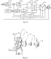
- At present, a semi-closed loop control mode is mainly adopted by a monitoring device to control the motor motion. As shown in the semi-closed loop control shown in
Fig. 1 , the singlechip outputs a subdivision control signal to a driving circuit, which drives a stepping motor and then drives the body of the monitoring device to move. When the body of the monitoring device touches a photoelectric switch, the photoelectric switch feeds back a photoelectric signal to the singlechip, which calibrates the initial position of the stepping motor. In the above-mentioned semi-closed loop control mode, the calibration of the initial position of the stepping motor is started only when the body of the monitoring device touches the photoelectric switch. However, the body of the monitoring device can touch the photoelectric switch only once during one rotation, which leads to the insufficient precision of the initial position calibration of the stepping motor and the insufficient control precision of the monitoring device over the body motion. - In order to improve the control precision of the monitoring device over the motor motion, an embodiment of the present application provides a monitoring device, which may be a device with PT control such as a ball machine, a pan-tilt device.
- The structure of the monitoring device according to an embodiment of the present application is shown in
Fig. 2 , which includes aphysical parameter sensor 21, aplatform chip 22, acontroller 23, asinglechip 24, adriving circuit 25, amotor 26, and amagnetic encoder chip 27. Wherein, thephysical parameter sensor 21 is connected to the first end of theplatform chip 22, the second end of theplatform chip 22 is connected to the first end of thecontroller 23, the second end of thecontroller 23 is connected to the first end of thesinglechip 24, the second end of thesinglechip 24 is connected to the first end of thedriving circuit 25, and the second end of thedriving circuit 25 is connected to the first end of themotor 26. Themotor 26 may be a two-phase motor or a three-phase motor. - In the monitoring device according to an embodiment of the present application, the
platform chip 22 is configured to send a motion command to themotor 26. - Wherein, the motion command may be input by a user to the monitoring device or received by the monitoring device from another electronic device. The motion command is used to indicate the body rotation of the monitoring device. The motion command may include information such as the rotation angle and rotation speed of the body.
- The
motor 26 is configured to rotate according to the motion command and drive the body of the monitoring device to rotate. - The
physical parameter sensor 21 is configured to acquire the first physical parameter of the body of the monitoring device and send the first physical parameter to theplatform chip 22. - In one embodiment, the
physical parameter sensor 21 may include a position sensor and/or a speed sensor; the first physical parameter includes position information and/or speed information. The position sensor is configured to acquire the position information of the body of the monitoring device, and the speed sensor is configured to acquire the speed information of the body of the monitoring device. The position information may also be called position data, and the speed information may also be called motion speed data. - The position information of the body of the monitoring device may include the rotation angle of the body. In one example, the rotation angle of the body is the rotation angle relative to the initial position of the body. Here, the initial position of the body is the position where the body is stationary. The speed information of the body of the monitoring device may include the rotation speed of the body with a unit that may be degrees per second.
- Specifically, if the
physical parameter sensor 21 includes a position sensor, the first physical parameter includes position information. If thephysical parameter sensor 21 includes a speed sensor, the first physical parameter includes speed information. If thephysical parameter sensor 21 includes a position sensor and a speed sensor, the first physical parameter includes position information and speed information. - The
platform chip 22 is further configured to send the first physical parameter to thecontroller 23. - In an embodiment of the present application, the
platform chip 22 may be connected to thecontroller 23 through a serial port. That is to say, data communications between theplatform chip 22 and thecontroller 23 are realized through a serial port, and the level signal may be a TTL (Time To Live) level. Here, the level signal is the level signal between theplatform chip 22 and thecontroller 23. - The
magnetic encoder chip 27 is configured to acquire the second physical parameter of themotor 26 and send the second physical parameter to thecontroller 23. - In an embodiment of the present application, the
magnetic encoder chip 27 may be installed below the steel magnet of themotor 26, so that themagnetic encoder chip 27 can acquire the second physical parameter in real time and feed the signal back to thecontroller 23. - In one embodiment, the second physical parameter includes position information and/or speed information. Specifically, if the
physical parameter sensor 21 includes a position sensor, the first physical parameter includes position information, and the second physical parameter includes position information. If thephysical parameter sensor 21 includes a speed sensor, the first physical parameter includes speed information and the second physical parameter includes speed information. If thephysical parameter sensor 21 includes a position sensor and a speed sensor, the first physical parameter includes position information and speed information, and the second physical parameter includes position information and speed information. - In an embodiment of the present application, the position information of the
motor 26 may include the rotation angle of the motor. In one example, the rotation angle of the motor is the rotation angle relative to the initial position of the motor. The speed information of themotor 26 may include the rotation speed of the motor. The initial position of the motor is the position where the motor is stationary. - The
controller 23 is configured to determine the driving voltage of themotor 26 and generate a control command when the error between the first physical parameter and the second physical parameter is greater than a preset threshold, wherein the control command instructs that themotor 26 should be driven with the driving voltage; and send the control command to thesinglechip 24. - Due to the influence of external factors, the rotation speed of the motor may be different under the same torque. In an embodiment of the present application, the
controller 23 determines the driving voltage of themotor 26 in real time based on the first physical parameter and the second physical parameter, the driving voltages ofdifferent motors 26 may be determined based on different first physical parameters and second physical parameters, the torque input by themotor 26 is different under different driving voltages. Thecontroller 23 drives themotor 26 based on the determined driving voltage, and then calibrates the physical parameter of themotor 26, which may effectively reduce the error between the physical parameter of the body of the monitoring device and the physical parameter of themotor 26 caused by external factors. - The
singlechip 24 is configured to generate a driving signal according to the control command, and send the driving signal to the driving circuit, the driving signal instructs that themotor 26 should be driven with the driving voltage. - The driving
circuit 25 is configured to output the driving voltage according to the driving signal to drive themotor 26. - In the monitoring device according to an embodiment of the present application, the physical parameter sensor can acquire the physical parameter of the body of the monitoring device in real time, and the magnetic encoder chip can acquire the physical parameter of the motor in real time. The controller can determine in real time whether there is a deviation between the physical parameters of the motor and the body of the monitoring device, then calibrate the initial position of the motor in real time to realize the real-time control of the motor motion, thus improving the control precision of the monitoring device over the body motion.
- In an embodiment of the present application, in order to further improve the control precision of the motor motion, the
position sensor 211 and thespeed sensor 212 may be high-precision sensors. The precision of the position fed back by theposition sensor 211 may reach 0.04°. As an auxiliary reference sensor, thespeed sensor 212 feeds back the motion speed state of the body of the monitoring device in real time. Theposition sensor 211 and thespeed sensor 212 may be installed at the position of the synchronous wheel of the monitoring device, acquire the position information and speed information of the body of the monitoring device in real time, and eliminate the pulley error. - The above-mentioned motion speed state of the body may include the speed information of the body.
- In addition, the
position sensor 211 and thespeed sensor 212 may be integrated on one PCB (Printed Circuit Board). As shown inFig. 11 , the structure of the bottom of the monitoring device includes asupport frame 1, arotating shaft 2 of the monitoring device, a bearing 3, amagnet holder 4, asteel magnet 5 and asensor mounting plate 6. The bearing 3 is sleeved outside therotating shaft 2, and thesteel magnet 5 is fixedly installed on themagnet holder 4, one end of which is sleeved within the bearing 3, so that thesteel magnet 5 rotates along with therotating shaft 2, thereby changing the magnetic field at the bottom of the monitoring device. Thesensor mounting plate 6 is installed below themagnet holder 4 and thesteel magnet 5 without contacting with thesteel magnet 5. Theposition sensor 211 and thespeed sensor 212 may be mounted on thesensor mounting plate 6 parallel to the bearing 3. In addition, the magnetic field at the bottom of the monitoring device changes with the rotation of therotating shaft 2, and then theposition sensor 211 and thespeed sensor 212 can determine the relative motion of therotating shaft 2, and the position information and the speed information of the body can be calculated through conversion by detecting the relative motion of therotating shaft 2. - In an embodiment of the present application, the communications structure between the
physical parameter sensor 21 and theplatform chip 22 may be regarded as a closed-loop system, which is called a body closed-loop system. Thephysical parameter sensor 21 may communicate with theplatform chip 22 via a serial port. For example, thephysical parameter sensor 21 may be connected to theplatform chip 22 via an SPI (Serial Peripheral Interface) bus. - In an alternative embodiment, the
physical parameter sensor 21 includes aposition sensor 211 and aspeed sensor 212. Specifically, the communication mode of the closed-loop system of the body is shown inFig. 3 . Theplatform chip 22 is connected to theposition sensor 211 and thespeed sensor 212 through an SPI bus; theplatform chip 22 is connected to theposition sensor 211 through one chip select pin, and theplatform chip 22 is connected to thespeed sensor 212 through another chip select pin. - The communication mode between the
position sensor 211, thespeed sensor 212 and theplatform chip 22 is shown inFig. 3 . SPI1_MOSI (master output slave input) is a signal sent by theplatform chip 22 to theposition sensor 211 and thespeed sensor 212, SPI1_MISO (master input slave output) signal is a signal sent by theposition sensor 211 and thespeed sensor 212 to theplatform chip 22, SPI1_CLK(Clock) signal is a clock signal, and CS_1 signal is a signal to a CS (Chip Select) pin of theposition sensor 211, CS_2 signal is a signal to a CS pin of thespeed sensor 212. The communication mode of SPI bus is adopted, the sensor types and data are distinguished through CS, and the time division multiplexing communications betweenposition sensor 211,speed sensor 212 andplatform chip 22 are realized. - Based on the communications structure shown in
Fig. 3 , the time division multiplexing flowchart of the closed-loop system of the body is shown inFig. 4 . - Step 41: selecting the
platform chip 22 as a master and theposition sensor 211 and thespeed sensor 212 as slaves. - Step 42: providing SPI bus interfaces on the master and two slaves, and connecting the master and the slaves via the SPI bus interfaces.
-
Step 43, providing on the master two chip select control interfaces that are connected to the two slaves respectively, wherein the time division multiplexing communications between the master and the slaves are realized through the chip select control signal sent by the master. - For example, the
platform chip 22 sends a CS_1 signal to theposition sensor 211 when communicated with theposition sensor 211, and sends a CS_2 signal to thespeed sensor 212 when communicated with thespeed sensor 212. - In an alternative embodiment,
Fig. 5 shows another structural schematic diagram of the monitoring device according to an embodiment of the present application, which may further include acurrent sampling circuit 28 and an analog-digital acquisition unit 29 on the basis ofFig. 2 . The first end of thecurrent sampling circuit 28 is connected to the second end of themotor 26, the second end of thecurrent sampling circuit 28 is connected to the first end of the analog-digital acquisition unit 29, and the second end of the analog-digital acquisition unit 29 is connected to the third end of thecontroller 23. - In an embodiment of the present application, the
current sampling circuit 28 is configured to acquire the sampling current output by themotor 26, convert the sampling current into a sampling voltage, and send the sampling voltage to the analog-digital acquisition unit 29. The analog-digital acquisition unit 29 is configured to acquire the sampling voltage output by the current sampling circuit and send the acquired sampling voltage to thecontroller 23. Thecontroller 23 may further be configured to adjust the driving voltage of themotor 26 according to the sampling voltage. - Specifically, the
controller 23 determines the driving voltage of the motor when the error between the first physical parameter and the second physical parameter is greater than a preset threshold, and adjusts the driving voltage of themotor 26 according to the sampling voltage, so as to quickly calibrate the position and speed of themotor 23 to avoid overshoot. In addition, the analog-digital acquisition unit 29 may select a 10-bit sensor to acquire the sampling voltage output by thecurrent sampling circuit 28 with high precision. - In an embodiment of the present application, the communications structure for communications among the
controller 23, thesinglechip 24, the drivingcircuit 25, themotor 26, themagnetic encoder chip 27, thecurrent sampling circuit 28 and the analog-digital acquisition unit 29 may be regarded as a closed-loop system, which is called a motor closed-loop system. - The
controller 23 may be connected to thesinglechip 24 through a serial port, that is to say, thecontroller 23 and thesinglechip 24 communicate with each other via a serial port, and the level signal is a TTL(Time To Live) level. Here, the level signal is the level signal between thecontroller 23 and thesinglechip 24. - The
singlechip 24 may be connected to the drivingcircuit 25 via a PWM(Pulse Width Modulation) line, that is, thesinglechip 24 communicates with the drivingcircuit 25 by PWM pulse control. - The driving
circuit 25 may drive themotor 26 by outputting a voltage. - The
controller 23 may be connected to themagnetic encoder chip 27 via a serial port, that is, data communications between thecontroller 23 and themagnetic encoder chip 27 are realized via a serial port, and the level signal is a TTL level. The level signal here is the level signal between thecontroller 23 and themagnetic encoder chip 27. - The driving
circuit 25 drives themotor 26 by outputting a voltage, and then themotor 26 outputs a corresponding current. As shown inFig. 6 , themotor 26 outputs three-phase currents of la, Ib and Ic. Thecurrent sampling circuit 28 converts the three-phase currents of la, Ib and Ic into three-phase voltages and transmits them to the analog-digital acquisition unit 29. - The analog-
digital acquisition unit 29 may be connected to thecontroller 23 via an I2C (Inter-Integrated Circuit) bus, that is, the data communications between the analog-digital acquisition unit 29 and thecontroller 23 are realized by the communication mode of I2C, and the level signal is a TTL level. The level signal here is the level signal between the analog-digital acquisition unit 29 and thecontroller 23. - In an alternative embodiment, the communication mode of the motor closed-loop system is shown in
Fig. 6 . The USART (Universal Synchronous/Asynchronous Receiver/Transmitter) _TXD (Transmit Data) is data sent by thecontroller 23 to thesinglechip 24 or data sent by thesinglechip 24 to thecontroller 23, USART_RXD (Receive Data) is data received by thecontroller 23 from thesinglechip 24 or data received by thesinglechip 24 from thecontroller 23; PWM A, PWM B and PWM C are pulse signals sent by thesinglechip 24 to the drivingcircuit 25; PHASE A, PHASE B and PHASE C are phase signals sent by thesinglechip 24 to the drivingcircuit 25; OUT A, OUT B and OUT C are three-phase voltages output by the drivingcircuit 25 to themotor 26; SPI2_MOSI is a signal sent by thecontroller 23 to themagnetic encoder chip 27, SPI2_MISO is a signal sent by themagnetic encoder chip 27 to thecontroller 23, SPI2_CLK is a clock signal, and CS is a signal to the CS pin of themagnetic encoder chip 27; la, Ib and Ic are three-phase currents output by themotor 26 to thecurrent sampling circuit 28, and Ua, Ub and Uc are three-phase voltages output by thecurrent sampling circuit 28 to the analog-digital acquisition unit 29; I2C_SDA is serial data and I2C_SCK is a serial clock signal. - Through the above motor closed-loop system, the
controller 23 can acquire the position information and speed information of themotor 26, as well as the output current and voltage of themotor 26 in real time. Thecontroller 23 calibrates the initial position of the motor in real time based on the position information and speed information of themotor 26, the output current and voltage of themotor 26, so as to realize the real-time control of the motor motion, and further improve the control precision of the monitoring device over the body motion. - A schematic diagram illustrating the communications in motor motion control as shown in
Fig. 7 is obtained by combining the communications structures shown inFigs. 3 and6 . Through the communications structure shown inFig. 7 , the control of the motor motion is realized, thus improving the control precision of the monitoring device over the body motion. - In an alternative embodiment, the
controller 23 may be specifically configured to convert the second physical parameter into the third physical parameter of the body of the monitoring device according to a conversion relationship between the physical parameter of the body of the monitoring device and the physical parameter of themotor 26; compare the first physical parameter with the third physical parameter; when the error between the first physical parameter and the third physical parameter is greater than or equal to a preset threshold, determine the driving voltage of themotor 26 and generate a control command; and send the control command to thesinglechip 24. - The above preset threshold may be set according to actual requirements. For example, if the physical parameters include position information and speed information, the preset threshold may include a preset position threshold corresponding to the position information and a preset speed threshold corresponding to the speed information. The preset position threshold may be 0.01°, 0.02°, etc., and the preset speed threshold may be 0.1°/s, 0.2°/s, which are not specifically limited.
- In one embodiment, the
controller 23 may be a PID (Proportion Integration Differentiation) controller. The PID controller consists of a proportional unit, an integral unit and a differential unit. The basis of PID control is proportional control; integral control may eliminate steady-state errors, but may increase overshoot; differential control may accelerate the response speed of an inertial system and reduce the overshoot trend. - In one example, the physical parameters include speed information and position information. Take the preset position threshold of 0.01° and the preset speed threshold of 0.1°/s as an example. The
motor 26 is driven based on the PID controller, and the process of calibrating the physical parameter of themotor 26 is shown inFig. 8 , including the following steps. - In
step 81, the monitoring device is powered on. - In
step 82, it is determined whether the communications between various parts of hardware of the monitoring device is abnormal. If the communications between various parts of hardware is abnormal,step 83 is executed. If the communications between various parts of hardware is normal,step 84 is executed. - In
step 83, themotor 26 is initialized to ensure normal communications between various parts of hardware. - In
step 84, it is determined whether the PID controller normally receives the position information L a1 and speed information v a1 of themotor 26 fed back by themagnetic encoder chip 27, and determined whether the PID controller normally receives the position information L b1 of the body of the monitoring device acquired by theposition sensor 211 and the speed information v b1 of the body of the monitoring device acquired by thespeed sensor 212. If both the results in the above two determinations are positive,step 85 is executed. Otherwise, step 86 is executed. - Wherein, the
magnetic encoder chip 27 acquires the position information L a1 of themotor 26 and sends the position information L a1 to the PID controller. Thecontroller 23 converts the position information L a1 into the position information L c1 of the body of the monitoring device. Theposition sensor 211 acquires the position information L b1 of the body of the monitoring device and sends the position information L b1 to theplatform chip 22, and theplatform chip 22 sends the position information L b1 to the PID controller. - In
step 85, the PID controller compares whether the position information L b1 and the position information L c1 are equal. If yes, step 87 is executed. Otherwise, step 86 is executed. - In
step 86, the PID controller reports an error through an OSD (On Screen Display) interface, and saves the error information, so that the user may handle it in time and eliminate the error. - In
step 87, the PID controller displays that the self-check is successful through the OSD interface. - In
step 88, theplatform chip 22 waits to receive the motion command in real time. If theplatform chip 22 does not receive a motion command,step 89 is executed. If a motion command is received,step 810 is executed. - In
step 89, themotor 26 is locked with high strength, and the body of the monitoring device does not rotate. - In
step 810, when receiving the motion command, theplatform chip 22 controls the body of the monitoring device to rotate. At this time, themagnetic encoder chip 27 acquires the position information L a2 of themotor 26 and sends the position information L a2 to the PID controller, the PID controller converts the position information L a2 into the position information L c2 of the body of the monitoring device. Theposition sensor 211 acquires the position information L b2 of the body of the monitoring device and sends the position information L b2 to theplatform chip 22, theplatform chip 22 sends the position information L b2 to the PID controller. The PID controller compares and determines whether the error between the position information L b2 and the position information L c2 is greater than or equal to 0.01°. If yes, step 811 is executed. Otherwise,step 813 is executed. - In
step 811, the PID controller starts a proportional adjustment algorithm to determine the reference voltage of the driving motor. The error can be eliminated below 0.01° by driving the motor with the reference voltage. - In
step 812, the PID controller compares and determines whether the error between the position information L b3 and the position information L c3 is less than 0.01°. If yes, step 813 is executed. Otherwise, the process returns to step 811. - Wherein, the position information L b3 is the position information the
position sensor 211 acquires the position information of the body of the monitoring device in real time. The position information L c3 is the position information of the body of the monitoring device obtained by converting the position information of themotor 26 acquired by themagnetic encoder chip 27 in real time. - In
step 813, the PID controller starts an integral-differential adjustment algorithm to adjust the reference voltage to obtain the driving voltage. The error can be controlled at 0° by driving the motor with the reference voltage. - After determining the driving voltage, the PID controller generates a control command that instructs that the motor should be driven with the driving voltage, and sends the control command to the
singlechip 24. Thesinglechip 24 generates, according to the control command, a driving signal that instructs that the motor should be driven with the driving voltage, and sends the driving signal to the driving circuit, the driving circuit outputs a driving voltage according to the driving signal to drive themotor 26. - In
step 814, the PID controller acquires the position information of the body of the monitoring device acquired by theposition sensor 211 in real time, and determines whether the body of the monitoring device moves to a designated position. If yes, step 815 is executed. Otherwise, steps 810 and 816 are executed. - The PID controller acquires the position information of the body of the monitoring device acquired by the
position sensor 211 in real time, which is specifically as follows: theposition sensor 211 acquires the position information of the body of the monitoring device in real time, and sends the acquired position information to theplatform chip 22, and theplatform chip 22 sends the acquired position information to the PID controller. - In
step 815, themotor 26 is locked with high strength, and the body of the monitoring device does not rotate. - In step 816: when receiving the motion command, the
platform chip 22 controls the body of the monitoring device to rotate. At this time, themagnetic encoder chip 27 acquires the speed information v a2 of themotor 26 and sends the speed information v a2 to the PID controller; the PID controller converts the speed information v a2 into the speed information v c2 of the body of the monitoring device. Thespeed sensor 212 acquires the speed information v b2 of the body of the monitoring device, and sends the speed information v b2 to theplatform chip 22, and theplatform chip 22 sends the speed information v b2 to the PID controller. The PID controller compares and determines whether the error between the speed information v b2 and the speed information v c2 is greater than or equal to 0.1°/s. If yes, step 817 is executed. Otherwise,step 814 is executed. - In step 817: the PID controller starts the proportional adjustment algorithm to determine the reference voltage of the driving motor. The error can be eliminated below 0.1°/s by driving the motor with the reference voltage.
- In
step 818, the PID controller compares and determines whether the error between the speed information v b3 and the speed information v c3 is less than 0.1°/s. If yes, step 819 is executed. Otherwise, the process returns to step 817. - Wherein the speed information v b3 is the speed information of the body of the monitoring device acquired by the
speed sensor 212 in real time. The speed information v c3 is the speed information of the body of the monitoring device obtained by converting the speed information of themotor 26 acquired by themagnetic encoder chip 27 in real time. - In
step 819, the PID controller starts the integral-differential adjustment algorithm to adjust the reference voltage to obtain the driving voltage. The error can be controlled at 0°/s by driving the motor with the reference voltage. Step 814 is executed again. - After determining the driving voltage, the PID controller generates a control command that instructs that the motor should be driven with the driving voltage, and sends the control command to the
singlechip 24, thesinglechip 24 generates a driving signal according to the control command, and sends the driving signal to the driving circuit, the driving circuit outputs a driving voltage according to the driving signal to drive themotor 26, wherein the driving signal instructs that the motor should be driven with the driving voltage. - In an embodiment of the present application, the high-precision control of the motor motion is realized through the above steps 81-819.
- In an alternative embodiment, the
current sampling circuit 28 shown inFig. 9 may include afirst resistor 281, adifferential amplifier 282, anoperational amplifier 283, asecond resistor 284, athird resistor 285, afirst capacitor 286, asecond capacitor 287, athird capacitor 288, afourth capacitor 289, afifth capacitor 2810, afourth resistor 2811 and afifth resistor 2812; - the first end of the
first resistor 281 is connected to themotor 26, the first end of thefirst resistor 281 is connected to the first end of thedifferential amplifier 282, and the second end of thefirst resistor 281 is connected to the second end of thedifferential amplifier 282; - the first end of the
first capacitor 286 is grounded, the second end of thefirst capacitor 286 is connected to the first end of thedifferential amplifier 282, the first end of thesecond capacitor 287 is connected to the first end of thedifferential amplifier 282, the second end of thesecond capacitor 287 is connected to the second end of thedifferential amplifier 282, the first end of thethird capacitor 288 is grounded, and the second end of thethird capacitor 288 is connected to the second end of thedifferential amplifier 282; - the third end of the
differential amplifier 282 is grounded, the fourth and fifth ends of thedifferential amplifier 282 are connected to the first end of thesecond resistor 284, the second end of thesecond resistor 284 is connected to the first end of thethird resistor 285, and the second end of thethird resistor 285 is connected to the first end of theoperational amplifier 283; - the first end of the
fourth capacitor 289 is connected to the first end of thethird resistor 285, the second end of thefourth capacitor 289 is grounded, the first end of thefifth capacitor 2810 is connected to the first end of theoperational amplifier 283, and the second end of thefifth capacitor 2810 is grounded; - the second end of the
operational amplifier 283 is connected to the first end of thefifth resistor 2812, the third end of theoperational amplifier 283 is connected to the second end of thefifth resistor 2812, the second end of thefifth resistor 2812 is connected to the first end of thefourth resistor 2811, the second end of thefourth resistor 2811 is grounded, and the second end of theoperational amplifier 283 is connected to the analog-digital acquisition unit 29. - Based on the
current sampling circuit 28, the sampling current is converted into a voltage signal through thefirst resistor 281. Thefirst capacitor 286, thesecond capacitor 287 and thethird capacitor 288 perform first-order filtering, that is, filter the voltage signal. Thereafter, the voltage signal is converted into a single-ended signal by thedifferential amplifier 282. Thesecond resistor 284 and thethird resistor 285 are used as balance resistors to protect the precision resistors inside thedifferential amplifier 282. Theoperational amplifier 283 amplifies the voltage value of the single-ended signal to a preset voltage value range to obtain a sampling voltage, so as to improve the conversion resolution. At the same time, thefourth capacitor 289 and thefifth capacitor 2810 perform second-order filtering on the single-ended signal, that is, low-pass filtering on the single-ended signal, so as to remove interference, ensure the voltage measurement range, improve the signal-to-noise ratio, and provide a good voltage input signal for the analog-digital acquisition unit 29. - In an alternative embodiment, the internal circuit of the PID controller is shown in
Fig. 10 . Thesinglechip 24, the drivingcircuit 25, thecurrent sampling circuit 28 and the analog-digital acquisition unit 29 are not shown inFig. 10 , which simply shows the internal circuit of the PID controller, themotor 26 and themagnetic encoder chip 27. The PID controller includes a firstproportional regulator 231, an integral-differential regulator 232, afirst filter circuit 233, a voltage space vectorpulse width modulator 234, afunction generator 235, a secondproportional regulator 236, anintegral regulator 237, asecond filter circuit 238 and acurrent detection circuit 239. Wherein, thefirst filter circuit 233 and thesecond filter circuit 238 may be MT/αβ circuits. - The first end of the first
proportional regulator 231 is connected to themagnetic encoder chip 27, the second end of the firstproportional regulator 231 is connected to the first end of the integral-differential regulator 232, and the second end of the integral-differential regulator 232 is connected to the first end of thefirst filter circuit 233; - the first end of the
function generator 235 is connected to themagnetic encoder chip 27, the second end of thefunction generator 235 is connected to the first end of the secondproportional regulator 236, the second end of the secondproportional regulator 236 is connected to the first end of theintegral regulator 237, and the second end of theintegral regulator 237 is connected to the second end of thefirst filter circuit 238; - the first end of the
current detection circuit 239 is connected to themotor 26, the second end of thecurrent detection circuit 239 is connected to the first end of thesecond filter circuit 238, the second end of thesecond filter circuit 238 is connected to themagnetic encoder chip 27, the third end of thesecond filter circuit 238 is connected to the first end of the integral-differential regulator 232, and the fourth end of thesecond filter circuit 232 is connected to the first end of theintegral regulator 236; - the third end of the
first filter circuit 233 is connected to the first end of the voltage space vectorpulse width modulator 234. Wherein, the voltage space vectorpulse width modulator 234 may be connected to thesinglechip 24. - It may be understood that the first end of the
current detection circuit 239 is connected to themotor 26, which means that the first end of thecurrent detection circuit 239 is connected to the analog-digital acquisition unit 29, the analog-digital acquisition unit 29 is connected to thecurrent sampling circuit 28, and thecurrent sampling circuit 28 is connected to themotor 26, so that the first end of thecurrent detection circuit 239 is connected to themotor 26. - In an embodiment of the present application, when the PID controller adjusts the motor motion, the above internal circuit may be divided into a position control loop and a current control loop.
- Position control loop: the first
proportional regulator 231 and the integral-differential regulator 232 perform proportional, integral and differential operations based on the position information and speed information of themotor 26 fed back by themagnetic encoder chip 27 to determine the driving voltage; thefunction generator 235 compensates for the motion feedback of themotor 26, thefunction generator 235 performs algorithm compensation on the position information of themotor 26 fed back by themagnetic encoder chip 27, and determines the difference between the position information of the motor required by the PID controller and the actual position information of the motor, that is, the compensated position information of the motor, and the secondproportional regulator 236 and theintegral regulator 237 perform proportional and integral operations on the compensated position information of the motor to obtain compensation data; thefirst filter circuit 233 filters the driving voltage and compensation data, and inputs the filtered driving voltage into the voltage space vectorpulse width modulator 234; the voltage space vectorpulse width modulator 234 generates a pulse command based on the filtered driving voltage, and then the driving circuit outputs the driving voltage to themotor 26 based on the pulse command. The pulse command is the above driving signal. The pulse command includes a first pulse command and a second pulse command. The specific uses of the first pulse command and the second pulse command will be described in detail below, and will not be described here. - Current control loop: the
current detection circuit 239 detects the current fed back by themotor 26 and inputs the current to thesecond filter circuit 238; thesecond filter circuit 238 filters the current and sends the filtered current to the integral-differential regulator 232 and the secondproportional regulator 236; the integral-differential regulator 232 and the secondproportional regulator 236 perform proportional, integral and differential operations on the position information of themotor 26 based on the current to accurately determine the driving voltage of themotor 26. - In an embodiment of the present application, the voltage space vector
pulse width modulator 234 adjusts the filtered driving voltage and filtered driving current, and outputs the driving voltage to themotor 26. The phase number of the driving voltage output by the voltage space vectorpulse width modulator 234 to themotor 26 corresponds to the phase number of themotor 26. For example, themotor 26 is a three-phase motor, and the voltage space vectorpulse width modulator 234 outputs a three-phase driving voltage to themotor 26, as shown inFig. 10 . - In addition, in an embodiment of the present application, before the
second filter circuit 238 inputs the filtered current into the integral-differential regulator 232 and the secondproportional regulator 236, proportional and integral operations can be performed on the current, and then the integral-differential regulator 232 and the secondproportional regulator 236 perform proportional, integral and differential operations on the position information of themotor 26 based on the results of the proportional and integral operations to determine the driving voltage of themotor 26. The voltage of the driving motor is adjusted through the current control loop in combination with the position control loop. Therefore, only proportional and integral control can be performed on the current, without differential control, which saves the cost of the PID controller. - Again, the voltage of the driving motor is adjusted and the current fed back by the
motor 26 is monitored in real time through the current control loop in combination with the position control loop, to monitor the current and avoid the overshoot of the voltage output by the position control loop. In addition, in the technical solution according to an embodiment of the present application, the current control loop is provided, and corresponding amount of current may be output as required, so that the motion control efficiency of themotor 26 is greatly improved. - In one example, the first
proportional regulator 231 and the secondproportional regulator 236 may perform a proportional operation on the position information of themotor 26 by using the following formula (1), to determine the first proportional gain, and then adjust the driving voltage of themotor 26 based on the first proportional gain.
- In formula (1), Y_Kp is a first proportional gain, Ts is the switching period of
motor 26, spd_cont is the speed constant of themotor 26, gain_ad is the inertia constant of themotor 26, gain_ad=Rs∗Kad, Rs is the internal resistance of themotor 26, Kad is the current value of themotor 26, and J is the moment of inertia of themotor 26. - In one example, the integral-
differential regulator 232 and theintegral regulator 237 may perform an integral operation on the position information of themotor 26 by using the following formula (2), to determine the first integral gain, and then adjust the driving voltage of the motor based on the first integral gain.
- In the formula (2), Y_Ki represents the first integral gain, s represents the position of the
motor 26, and fz1 and fp1 represent the rotation frequency of themotor 26, where the value range of fz1 is from 0.2Hz to 2Hz, and the value range of fp1 is from 100 to 200∗fz1. - The integral-
differential regulator 232 may perform an differential operation on the position information of themotor 26 by using the following formula (3) to determine a first differential gain, and then adjust the driving voltage of the motor based on the first differential gain.
- In the formula (3), Y_Kd represents the first differential gain, s represents the position of the
motor 26, and fz2 and fp2 represent the rotation frequency of themotor 26, wherein the value range of fz2 is 1/100fp1 and the value range of fp2 is from 200 to 500∗fz2. - In an embodiment of the present application, the PID controller may adjust the parameters in the above formulas (1), (2) and (3) based on the position information and speed information fed back by the
magnetic encoder chip 27, and then adjust the driving voltage of themotor 26, so as to realize high-precision and high-response motor motion control. - In an example, the following formula (4) may be used to perform a proportional operation on the acquired current value of the
motor 26, to determine the second proportional gain, and then adjust the driving current of the motor based on the second proportional gain.
- In formula (4), Current Kp is the second proportional gain, Vin represents the input voltage of the
motor 26, Lp represents the inductance of themotor 26, and gain_ad represents the inertia constant of themotor 26. - The above-mentioned proportional operation on the current value may be implemented by the
current detection circuit 239, and may be implemented by thesecond filter circuit 238, and may be implemented by a PID regulator that may be inserted between thecurrent detection circuit 239 and thesecond filter circuit 238, to which the present application is not particularly limited. - In one example, the following formula (5) may be used to perform an integral operation on the acquired current value of the
motor 26, to determine a second integral gain, and then adjust the driving current of the motor based on the second integral gain.
- In the formula (5), Current Ki is the second integral gain, Vin represents the input voltage of the
motor 26, Rs represents the internal resistance of themotor 26, Ts represents the switching period of themotor 26, and gain_ad is the inertia constant of themotor 26. - The above-mentioned integral operation on the current value may be implemented by the
current detection circuit 239, and may be implemented by thesecond filter circuit 238, and may be implemented by a PID regulator that may be inserted between thecurrent detection circuit 239 and thesecond filter circuit 238, to which the present application is not particularly limited. - In the embodiment of the present application, the signal output by the
motor 26 is fine-tuned based on the parameters in the above formulas (4) and (5), so as to realize high-precision and high-response motor motion control. - In an alternative embodiment, the
magnetic encoder chip 27 may be have a built-in 16-bit high-precision analog-digital sensor. One of these 16 bits is the status bit, and the position control precision can reach 360°/215 = 0.01°. Themagnetic encoder chip 27 may be installed below the steel magnet of the motor, so as to avoid failing to sense the state of the motor in real time due to the transmission error of themotor 26. - In an alternative embodiment, the
motor 26 may be a three-phase DC brushless motor. The three-phase DC brushless motor has characteristics of high efficiency and high response. The application of the three-phase brushless DC motor into the monitoring device can achieve high torque and high torque while taking into account the low-speed stability, and thus realize high-efficiency and high-response control of the motor motion. The introduction of three-phase DC brushless motor improves the torque and the rotating speed of a monitoring device with PT control, and then increases the product competitiveness of the monitoring device. - In one embodiment, the three-phase DC brushless motor has built-in 8 pairs of NS poles and 8 pairs of rotors, and the rotor of the three-phase DC brushless motor is a permanent magnet. The bottom of the motor is equipped with a magnet holder and a steel magnet, which move synchronously along with the motion of the motor and change the magnetic field at the bottom of the motor in real time. The three-phase DC brushless motor generates a magnetic field through the current between coils, and then drives the rotor inside the motor. In addition, the three-phase DC brushless motor rotates the rotor by changing the direction of the magnetic field generated by the surrounding coils, and controls the rotation speed of the rotor by controlling the direction and magnitude of the current to the coils.
- In an embodiment of the present application, the coils of the three-phase DC brushless motor are shown in
Fig. 12 . Based on the coils shown inFig. 12 , there are six energization modes of the three-phase DC brushless motor, including: phase A as an input and phase B as an output; phase A as an input and phase C as an output, phase B as an input and phase A as an output; phase C as an input and phase A as an output; phase C as an input and phase B as an output. - Compared with the three-phase DC brushless motor with the same specification, the torque of the stepping motor can be increased by 1.5 times and the maximum speed can be increased by 2 times.
- In an embodiment of the present application, the driving circuit needs to satisfy the following matrix:

- Wherein, Ua, Ub and Uc represent three-phase voltages; la, Ib and Ic represent three-phase currents; Rs represents the internal resistance of the
motor 26; Lij represents the mutual inductance of the i-phase internal resistance relative to the j-phase internal resistance of themotor 26; La, Lb and Lc represent the three-phase self-inductance of themotor 26; p represents a differential operator; and Ea, Eb and Ec represent the electromotive force of the three-phase stator phase windings. - In an alternative embodiment, the monitoring device may further include a PCB, wherein a
magnetic encoder chip 27 is mounted on the back of the PCB, and the steel magnet of the motor is placed directly above themagnetic encoder chip 27, and there is a gap between themagnetic encoder chip 27 and the steel magnet of the motor, that is, there is no contact between themagnetic encoder chip 27 and the steel magnet of the motor. The distance between themagnetic encoder chip 27 and the steel magnet may be calculated by simulation. When installing themagnetic encoder chip 27, it is necessary to ensure the installation precision and avoid inaccurate motor motion control caused by installation errors. - In an alternative embodiment, the monitoring device may further include a PCB and a heat radiator. A driving
circuit 25 is mounted on the front side of the PCB, and the drivingcircuit 25 is connected to the heat radiator. In practical applications, the drivingcircuit 25 will generate heat, and the drivingcircuit 25 can always work in an optimal environment by being connected to the heat radiator through thermal conductive materials such as thermal pads. - In an embodiment of the present application, the SPI bus may appear in the side direction of the body of the monitoring device to be connected to the
controller 23. - Based on the above monitoring device, an embodiment of the present application also provides a camera. Refer to
Fig. 13 , which is a structural schematic diagram of a camera according to an embodiment of the present application. The camera includes: - a
processor 131 configured to receive a pitching command input from outside and generate a pulse command for controlling the rotation of a motor according to the pitching command; - a
power driving circuit 132 connected to theprocessor 131 via a pulse width modulation line and configured to receive a pulse command from the processor and generate a corresponding three-phase voltage signal according to the pulse command; - a
motor 133 connected to thepower driving circuit 132 and configured to perform a corresponding rotation according to the three-phase voltage signal; - a
magnetic encoder chip 134 arranged at the bottom of themotor 133 and configured to acquire the current position data of themotor 133 during the corresponding rotation of the motor and transmit the current position data of the motor to theprocessor 131; - wherein the
processor 131 is further configured to acquire the current position data of the camera and receive the current position data of the motor from the magnetic encoder chip; calculate a first difference between the current position data of the camera and the current position data of the motor; generate a new first pulse command according to the first difference, wherein the new first pulse command is configured to control the motor to perform a new rotation so that the first difference is smaller than a preset position threshold. - In an embodiment of the present application, the
processor 131 may include aplatform chip 22, acontroller 23 and asinglechip 24, and may also include thecontroller 23 and thesinglechip 24. Theprocessor 131 is not specifically limited in the embodiments of the present application. Here, the functions and uses of theplatform chip 22, thecontroller 23 and thesinglechip 24 may be specifically referred to the description of the above-mentionedFigs. 2-12 . Thepower driving circuit 132 is the same as theabove driving circuit 25, themotor 133 is the same as theabove motor 26, and themagnetic encoder chip 134 is the same as the abovemagnetic encoder chip 27. The pitching command is the same as the above motion command. The current position data of the camera is the current position data of the body of the camera. - In the camera according to an embodiment of the present application, the processor acquires the position data of the motor and the position data of the camera in real time, and then the processor can determine whether there is a deviation between the position data of the motor and the position data of the camera in real time, so as to calibrate the motor in real time, realize the real-time control of the motor motion, and further improve the control precision of the camera over the body motion.
- In an alternative embodiment, the camera may further include:
a position sensor (not shown inFig. 13 ) configured to acquire the current position data of the camera in real time and transmit the current position data of the camera to the processor. - In an alternative embodiment, the
processor 131 may be specifically configured to:
when the first difference exceeds the preset position threshold, perform a proportional operation on the current position data of the motor to obtain a first proportional gain, under which the difference between the position data of the motor and the current position data of the camera is smaller than the preset position threshold; perform differential and integral operations on the current position data of the motor to obtain a first differential-integral gain, wherein the difference between the position data of the motor and the current position data of the camera is zero under the first proportional gain and the first differential-integral gain; generate a new first pulse command according to the first proportional gain and the first differential-integral gain. - In an alternative embodiment, the camera may further include:
- a speed sensor (not shown in
Fig. 13 ), which is configured to acquire current motion speed data of the camera in real time and transmit the current motion speed data of the camera to the processor; - in this case, the
magnetic encoder chip 134 is further configured to acquire the current motion speed data of the motor during the corresponding rotation of the motor, and transmit the current motion speed data of the motor to the processor; - the
processor 131 may be further configured to:
acquire the current motion speed data of the camera and receive the current motion speed data of the motor from the magnetic encoder chip; calculate a second difference between the current motion speed data of the camera and the current motion speed data of the motor; when the second difference exceeds the preset speed threshold, perform a proportional operation on the current motion speed data of the motor to obtain a second proportional gain, under which the difference between the motion speed data of the motor and the current motion speed data of the camera is smaller than the preset speed threshold; perform differential and integral operations on the current motion speed data of the motor to obtain a second differential-integral gain, wherein the difference between the motion speed data of the motor and the current motion speed data of the camera is zero under the second proportional gain and the second differential-integral gain; generate a new second pulse command according to the second proportional gain and the second differential-integral gain, wherein the new second pulse command is configured to control the motor to perform a new rotation so that the second difference is smaller than the preset speed threshold. - In an alternative embodiment, the precision of the position fed back by the position sensor reaches 0.04°, and the position sensor and the speed sensor are integrated on one PCB.
- In an alternative embodiment, the
processor 131 may be specifically configured to:
when the first difference exceeds the preset position threshold, perform proportional, integral and differential operations on the current position data of the motor to obtain data to be filtered; perform algorithm compensation on the current position data of the motor through a function generator, and perform proportional and integral operations on the compensated current position data of the motor to obtain compensation data; filter the data to be filtered and the compensation data to obtain filtered data; perform pulse width modulation on the filtered data to generate a new first pulse command. - In an alternative embodiment, the camera may further include:
a current sampling circuit, which is connected to the motor and the controller, and configured to sample a three-phase current flowing through the motor and send the three-phase current values of the sampled three-phase current to theprocessor 131; - In this case, the
processor 131 may be specifically configured to:
perform proportional and integral operations on the three-phase current values to obtain adjustment auxiliary data; when the first difference exceeds the preset position threshold, perform proportional, integral and differential operations on the current position data of the motor based on the adjustment auxiliary data to obtain data to be filtered; perform algorithm compensation on the current position data of the motor through a function generator, and perform proportional and integral operations on the compensated current position data of the motor based on the adjustment auxiliary data to obtain compensation data; filter the data to be filtered and the compensation data to obtain filtered data; perform pulse width modulation on the filtered data to generate a new first pulse command. - The specific details of the above-mentioned position sensor, speed sensor and current sampling circuit can refer to the description of
Figs. 2-12 . - The above-mentioned first end, second end, third end and fourth end are only for the purpose of distinguishing different ports of the devices, and have no limiting effect.
- It should be noted that in this application, relational terms such as first and second are only used to distinguish one entity or operation from another entity or operation, and do not necessarily require or imply any such actual relationship or sequence between these entities or operations. Moreover, the terms "comprising", "including" or any other variation thereof are intended to cover non-exclusive inclusion, so that a process, method, article or device that includes a series of elements includes not only those elements, but also other elements not explicitly listed, alternatively also elements inherent to such process, method, article or device. Without further restrictions, the element defined by the statement "including a ..." does not exclude the presence of additional identical elements in the process, method, article or device that includes the said element.
- All the embodiments in this specification are described in a related manner, and the same and similar parts of each embodiment may be referred to each other, and each embodiment focuses on the differences from the other embodiments. Especially, for the camera embodiment, since it is basically similar to the monitoring device embodiment, the description is relatively simple, and reference may be made to the partial description of the monitoring device embodiment for the relevant parts.
- The above are only preferred embodiments of the present application, and are not intended to limit the scope of protection of the present application. Any modification, equivalent replacement, improvement, etc. made within the spirit and principle of the present application are included in the scope of protection of the present application.
Claims (34)
- A monitoring device, comprising a physical parameter sensor, a platform chip, a controller, a singlechip, a driving circuit, a motor and a magnetic encoder chip;wherein, the platform chip is configured to send a motion command to the motor;the motor is configured to rotate according to the motion command and drive a body of the monitoring device to rotate;the physical parameter sensor is configured to acquire a first physical parameter of the body of the monitoring device and send the first physical parameter to the platform chip;the platform chip is further configured to send the first physical parameter to the controller;the magnetic encoder chip is configured to acquire a second physical parameter of the motor and send the second physical parameter to the controller;the controller is configured to determine a driving voltage of the motor and generate a control command when an error between the first physical parameter and the second physical parameter is greater than a preset threshold, wherein the control command instructs that the motor should be driven with the driving voltage; and send the control command to the singlechip;the singlechip is configured to generate a driving signal according to the control command and send the driving signal to the driving circuit, wherein the driving signal instructs that the motor should be driven with the driving voltage;the driving circuit is configured to output the driving voltage according to the driving signal to drive the motor.
- The monitoring device according to claim 1, wherein the controller is specifically configured to:convert the second physical parameter into a third physical parameter of the body of the monitoring device according to a conversion relationship between a physical parameter of the body of the monitoring device and a physical parameter of the motor;compare the first physical parameter with the third physical parameter;when an error between the first physical parameter and the third physical parameter is greater than or equal to a preset threshold, determine the driving voltage of the motor and generate a control command, and send the control command to the singlechip.
- The monitoring device according to claim 2, wherein the physical parameter sensor comprises a position sensor and/or a speed sensor; the first physical parameter and the second physical parameter comprise position information and/or speed information;the position sensor is configured to acquire position information of the body of the monitoring device in real time and transmit the position information of the body of the monitoring device to the controller;the speed sensor is configured to acquire speed information of the body of the monitoring device in real time and transmit the speed information of the body of the monitoring device to the controller;the magnetic encoder chip is specifically configured to acquire position information and speed information of the motor during a corresponding rotation of the motor, and transmit the position information and the speed information of the motor to the controller;the controller is specifically configured to calculate a first difference between the position information of the body of the monitoring device and the position information of the motor; calculate a second difference between the speed information of the body of the monitoring device and the speed information of the motor; when the first difference exceeds a preset position threshold or the second difference exceeds a preset speed threshold, perform a proportional operation on the position information and the speed information of the motor to obtain a proportional gain, under which a difference between the position information of the motor and the position information of the body of the monitoring device is smaller than the preset position threshold and a difference between the speed information of the motor and the speed information of the body of the monitoring device is smaller than the preset speed threshold; perform differential and integral operations on the position information and the speed information of the motor to obtain a differential-integral gain, wherein the difference between the position information of the motor and the position information of the body of the monitoring device is zero and the difference between the speed information of the motor and the speed information of the body of the monitoring device is zero under the proportional gain and the differential-integral gain; generate a new control command according to the proportional gain and the differential-integral gain.
- The monitoring device according to claim 3, wherein the platform chip is connected to the position sensor and the speed sensor via a serial peripheral interface bus;
the platform chip is connected to the position sensor through one chip select pin and to the speed sensor through another chip select pin. - The monitoring device according to claim 3, wherein precision of a position fed back by the position sensor reaches 0.04, and the position sensor and the speed sensor are integrated on one PCB (printed circuit board).
- The monitoring device according to claim 1, wherein the controller is a PID (Proportion Integration Differentiation) controller.
- The monitoring device according to claim 6, wherein the PID controller comprises a first proportional regulator, an integral-differential regulator, a first filter circuit, a voltage space vector pulse width modulator, a function generator, a second proportional regulator, an integral regulator, a second filter circuit and a current detection circuit;a first end of the first proportional regulator is connected to the magnetic encoder chip, a second end of the first proportional regulator is connected to a first end of the integral-differential regulator, and a second end of the integral-differential regulator is connected to a first end of the first filter circuit;a first end of the function generator is connected to the magnetic encoder chip, a second end of the function generator is connected to a first end of the second proportional regulator, a second end of the second proportional regulator is connected to a first end of the integral regulator, and a second end of the integral regulator is connected to a second end of the first filter circuit;a first end of the current detection circuit is connected to the motor, a second end of the current detection circuit is connected to a first end of the second filter circuit, a second end of the second filter circuit is connected to the magnetic encoder chip, a third end of the second filter circuit is connected to the first end of the integral-differential regulator, and a fourth end of the second filter circuit is connected to the first end of the integral regulator;a third end of the first filter circuit is connected to a first end of the voltage space vector pulse width modulator, and a second end of the voltage space vector pulse width modulator is connected to the singlechip.
- The monitoring device according to claim 7, wherein the first proportional regulator and the second proportional regulator determine a first proportional gain Y_Kp by using the following formula:
 the integral-differential regulator determines a first differential gain Y_Kd and a first integral gain Y_Ki by using the following formulas:
 wherein, Ts represents a switching period of the motor, spd_cont represents a speed constant of the motor, gain_ad represents an inertia constant of the motor, J represents a moment of inertia of the motor, S represents a position of the motor, fz1, fp1, fz2 and fp2 represent a rotation frequency of the motor, and a value range of fz1 is from 0.2Hz to 2Hz, a value range of fp1 is from 100 to 200∗fz1, a value range of fz2 is 1/100fp1, and a value range of fp2 is from 200 to 500∗fz2.
 - The monitoring device according to claim 7, wherein the current detection circuit determines a second proportional gain Current Kp by using the following formula:
 the current detection circuit determines a second integral gain Current Ki by using the following formula:
 wherein, Vin represents an input voltage of the motor, Lp represents a inductance of the motor, gain_ad represents an inertia constant of the motor, Rs represents an internal resistance of the motor, and Ts represents a switching period of the motor.
 - The monitoring device according to claim 1, wherein the monitoring device further comprises a current sampling circuit and an analog-digital acquisition unit;the current sampling circuit is configured to acquire a sampling current output by the motor, convert the sampling current into a sampling voltage, and send the sampling voltage to the controller;the analog-digital acquisition unit is configured to acquire the sampling voltage output by the current sampling circuit and send the acquired sampling voltage to the controller;the controller is further configured to adjust the driving voltage according to the sampling voltage.
- The monitoring device according to claim 10, wherein the current sampling circuit comprises a first resistor, a differential amplifier, an operational amplifier, a second resistor, a third resistor, a first capacitor, a second capacitor, a third capacitor, a fourth capacitor, a fifth capacitor, a fourth resistor and a fifth resistor;a first end of the first resistor is connected to the motor and is connected to a first end of the differential amplifier, and a second end of the first resistor is connected to a second end of the differential amplifier;a first end of the first capacitor is grounded, a second end of the first capacitor is connected to the first end of the differential amplifier, a first end of the second capacitor is connected to the first end of the differential amplifier, a second end of the second capacitor is connected to the second end of the differential amplifier, a first end of the third capacitor is grounded, and a second end of the third capacitor is connected to the second end of the differential amplifier;a third end of the differential amplifier is grounded, fourth and fifth ends of the differential amplifier are connected to a first end of the second resistor, a second end of the second resistor is connected to a first end of the third resistor, and a second end of the third resistor is connected to a first end of the operational amplifier;a first end of the fourth capacitor is connected to the first end of the third resistor, a second end of the fourth capacitor is grounded, a first end of the fifth capacitor is connected to the first end of the operational amplifier, and a second end of the fifth capacitor is grounded;a second end of the operational amplifier is connected to a first end of the fifth resistor, a third end of the operational amplifier is connected to a second end of the fifth resistor, the second end of the fifth resistor is connected to a first end of the fourth resistor, a second end of the fourth resistor is grounded, and the second end of the operational amplifier is connected to the analog-digital acquisition unit.
- The monitoring device according to any one of claims 1 to 11, wherein the motor is a DC brushless motor.
- The monitoring device according to any one of claims 1 to 11, wherein a rotor of the motor is a permanent magnet, and a magnet holder and a steel magnet are located at a bottom of the motor.
- The monitoring device according to claim 13, wherein the magnetic encoder chip is installed on the PCB with a gap between the magnetic encoder chip and the steel magnet.
- The monitoring device according to any one of claims 1 to 11, wherein the monitoring device further comprises a heat radiator;
the driving circuit is mounted on the PCB and connected to the heat radiator. - A camera, comprising:a processor configured to receive a pitching command input from outside and generate a pulse command for controlling a rotation of a motor according to the pitching command;a power driving circuit connected to the processor via a pulse width modulation line and configured to receive a pulse command from the processor and generate a corresponding three-phase voltage signal according to the pulse command;a motor connected to the power driving circuit and configured to perform a corresponding rotation according to the three-phase voltage signal;a magnetic encoder chip arranged at a bottom of the motor and configured to acquire current position data of the motor during the corresponding rotation of the motor and transmit the current position data of the motor to the processor;wherein the processor is further configured to acquire current position data of the camera and receive the current position data of the motor from the magnetic encoder chip; calculate a first difference between the current position data of the camera and the current position data of the motor; generate a new first pulse command according to the first difference, wherein the new first pulse command is configured to control the motor to perform a new rotation so that the first difference is smaller than a preset position threshold.
- The camera according to claim 16, wherein the camera further comprises:
a position sensor configured to acquire the current position data of the camera in real time and transmit the current position data of the camera to the processor. - The camera according to claim 17, wherein the processor is specifically configured to:
when the first difference exceeds the preset position threshold, perform a proportional operation on the current position data of the motor to obtain a first proportional gain, under which a difference between position data of the motor and the current position data of the camera is smaller than the preset position threshold; perform differential and integral operations on the current position data of the motor to obtain a first differential-integral gain, wherein the difference between the position data of the motor and the current position data of the camera is zero under the first proportional gain and the first differential-integral gain; generate a new first pulse command according to the first proportional gain and the first differential-integral gain. - The camera according to claim 18, wherein the camera further comprises:a speed sensor, which is configured to acquire current motion speed data of the camera in real time and transmit the current motion speed data of the camera to the processor;wherein the magnetic encoder chip is further configured to acquire current motion speed data of the motor during the corresponding rotation of the motor, and transmit the current motion speed data of the motor to the processor;the processor is further configured to:
acquire the current motion speed data of the camera and receive the current motion speed data of the motor from the magnetic encoder chip; calculate a second difference between the current motion speed data of the camera and the current motion speed data of the motor; when the second difference exceeds a preset speed threshold, perform a proportional operation on the current motion speed data of the motor to obtain a second proportional gain, under which a difference between the motion speed data of the motor and the current motion speed data of the camera is smaller than the preset speed threshold; perform differential and integral operations on the current motion speed data of the motor to obtain a second differential-integral gain, wherein the difference between the motion speed data of the motor and the current motion speed data of the camera is zero under the second proportional gain and the second differential-integral gain; generate a new second pulse command according to the second proportional gain and the second differential-integral gain, wherein the new second pulse command is configured to control the motor to perform a new rotation, so that the second difference is smaller than the preset speed threshold. - The camera according to claim 19, wherein precision of a position fed back by the position sensor reaches 0.04°, and the position sensor and the speed sensor are integrated on one PCB (printed circuit board).
- The camera according to claim 16 or 17, wherein the processor is specifically configured to:
when the first difference exceeds the preset position threshold, perform proportional, integral and differential operations on the current position data of the motor to obtain data to be filtered; perform algorithm compensation on the current position data of the motor through a function generator, and perform proportional and integral operations on the compensated current position data of the motor to obtain compensation data; filter the data to be filtered and the compensation data to obtain filtered data; perform pulse width modulation on the filtered data to generate a new first pulse command. - The camera according to claim 21, wherein the camera further comprises:a current sampling circuit connected to the motor and the controller, and configured to sample a three-phase current flowing through the motor, and send three-phase current values of the sampled three-phase current to the processor;the processor is specifically configured to:
perform proportional and integral operations on the three-phase current values to obtain adjustment auxiliary data; when the first difference exceeds the preset position threshold, perform proportional, integral and differential operations on the current position data of the motor based on the adjustment auxiliary data to obtain data to be filtered; perform algorithm compensation on the current position data of the motor through a function generator, and perform proportional and integral operations on the compensated current position data of the motor based on the adjustment auxiliary data to obtain compensation data; filter the data to be filtered and the compensation data to obtain filtered data; perform pulse width modulation on the filtered data to generate a new first pulse command. - The camera according to claim 19, wherein the processor comprises a singlechip, a platform chip and a controller;wherein the platform chip is connected to the controller via a built-in integrated circuit, and configured to acquire the current position data and the current motion speed data of the camera and send the current position data and the current motion speed data of the camera to the controller;the controller is connected to the singlechip via a synchronous/asynchronous serial line, and configured to acquire the current position data and the current motion speed data of the motor received from the magnetic encoder chip; receive a pitching command input from outside; generate a control command for controlling the rotation of the motor according to the pitching command;the singlechip is connected to the power driving circuit by a pulse width modulation line, and configured to receive the control command sent by the controller, and generate a pulse command for controlling the rotation of the motor according to the control command.
- The camera according to claim 23, wherein the platform chip is connected to the position sensor and the speed sensor via a serial peripheral interface bus;
the platform chip is connected to the position sensor through one chip select pin and to the speed sensor through another chip select pin. - The camera according to claim 23, wherein the controller is a PID (Proportion Integration Differentiation) controller.
- The camera according to claim 25, wherein the PID controller comprises a first proportional regulator, an integral-differential regulator, a first filter circuit, a voltage space vector pulse width modulator, a function generator, a second proportional regulator, an integral regulator, a second filter circuit and a current detection circuit;a first end of the first proportional regulator is connected to the magnetic encoder chip, a second end of the first proportional regulator is connected to a first end of the integral-differential regulator, and a second end of the integral-differential regulator is connected to a first end of the first filter circuit;a first end of the function generator is connected to the magnetic encoder chip, a second end of the function generator is connected to a first end of the second proportional regulator, a second end of the second proportional regulator is connected to a first end of the integral regulator, and a second end of the integral regulator is connected to a second end of the first filter circuit;a first end of the current detection circuit is connected to the motor, a second end of the current detection circuit is connected to a first end of the second filter circuit, a second end of the second filter circuit is connected to the magnetic encoder chip, a third end of the second filter circuit is connected to the first end of the integral-differential regulator, and a fourth end of the second filter circuit is connected to the first end of the integral regulator;a third end of the first filter circuit is connected to a first end of the voltage space vector pulse width modulator, and a second end of the voltage space vector pulse width modulator is connected to the singlechip.
- The camera according to claim 26, wherein the first proportional regulator and the second proportional regulator determine a first proportional gain Y_Kp by using the following formula:
 the integral-differential regulator determines a first differential gain Y_Kd and a first integral gain Y_Ki by using the following formulas:
 wherein, Ts represents a switching period of the motor, spd_cont represents a speed constant of the motor, gain_ad represents an inertia constant of the motor, J represents a moment of inertia of the motor, S represents a position of the motor, fz1, fp1, fz2 and fp2 represent a rotation frequency of the motor, and a value range of fz1 is from 0.2Hz to 2Hz, a value range of fp1 is from 100 to 200∗fz1, a value range of fz2 is 1/100fp1, and a value range of fp2 is from 200 to 500∗fz2.
 - The camera according to claim 26, wherein the current detection circuit determines a second proportional gain Current Kp by using the following formula:
 the current detection circuit determines a second integral gain Current Ki by using the following formula:
 wherein, Vin represents an input voltage of the motor, Lp represents a inductance of the motor, gain_ad represents an inertia constant of the motor, Rs represents an internal resistance of the motor, and Ts represents a switching period of the motor.
 - The camera according to claim 23, wherein the monitoring device further comprises a current sampling circuit and an analog-digital acquisition unit;the current sampling circuit is configured to acquire a sampling current output by the motor, convert the sampling current into a sampling voltage, and send the sampling voltage to the controller;the analog-digital acquisition unit is configured to acquire the sampling voltage output by the current sampling circuit and send the acquired sampling voltage to the controller;the controller is further configured to adjust the driving voltage according to the sampling voltage.
- The camera according to claim 29, wherein the current sampling circuit comprises a first resistor, a differential amplifier, an operational amplifier, a second resistor, a third resistor, a first capacitor, a second capacitor, a third capacitor, a fourth capacitor, a fifth capacitor, a fourth resistor and a fifth resistor;a first end of the first resistor is connected to the motor and is connected to a first end of the differential amplifier, and a second end of the first resistor is connected to a second end of the differential amplifier;a first end of the first capacitor is grounded, a second end of the first capacitor is connected to the first end of the differential amplifier, a first end of the second capacitor is connected to the first end of the differential amplifier, a second end of the second capacitor is connected to the second end of the differential amplifier, a first end of the third capacitor is grounded, and a second end of the third capacitor is connected to the second end of the differential amplifier;a third end of the differential amplifier is grounded, fourth and fifth ends of the differential amplifier are connected to a first end of the second resistor, a second end of the second resistor is connected to a first end of the third resistor, and a second end of the third resistor is connected to a first end of the operational amplifier;a first end of the fourth capacitor is connected to the first end of the third resistor, a second end of the fourth capacitor is grounded, a first end of the fifth capacitor is connected to the first end of the operational amplifier, and a second end of the fifth capacitor is grounded;a second end of the operational amplifier is connected to a first end of the fifth resistor, a third end of the operational amplifier is connected to a second end of the fifth resistor, the second end of the fifth resistor is connected to a first end of the fourth resistor, a second end of the fourth resistor is grounded, and the second end of the operational amplifier is connected to the analog-digital acquisition unit.
- The camera according to any one of claims 16 to 30, wherein the motor is a DC brushless motor.
- The camera according to any one of claims 16 to 30, wherein a rotor of the motor is a permanent magnet, and a magnet holder and a steel magnet are located at a bottom of the motor.
- The camera according to claim 30, wherein the magnetic encoder chip is installed on the PCB with a gap between the magnetic encoder chip and the steel magnet.
- The camera according to any one of claims 16 to 30, wherein the monitoring device further comprises a heat radiator;
the driving circuit is mounted on the PCB and connected to the heat radiator.
Applications Claiming Priority (2)
| Application Number | Priority Date | Filing Date | Title |
|---|---|---|---|
| CN202010113707.9A CN113300643B (en) | 2020-02-24 | 2020-02-24 | Monitoring equipment and camera |
| PCT/CN2020/131370 WO2021169442A1 (en) | 2020-02-24 | 2020-11-25 | Monitoring device and camera |
Publications (3)
| Publication Number | Publication Date |
|---|---|
| EP4113824A1 true EP4113824A1 (en) | 2023-01-04 |
| EP4113824A4 EP4113824A4 (en) | 2023-08-23 |
| EP4113824B1 EP4113824B1 (en) | 2024-10-30 |
Family
ID=77318534
Family Applications (1)
| Application Number | Title | Priority Date | Filing Date |
|---|---|---|---|
| EP20921543.3A Active EP4113824B1 (en) | 2020-02-24 | 2020-11-25 | Monitoring device |
Country Status (3)
| Country | Link |
|---|---|
| EP (1) | EP4113824B1 (en) |
| CN (1) | CN113300643B (en) |
| WO (1) | WO2021169442A1 (en) |
Families Citing this family (6)
| Publication number | Priority date | Publication date | Assignee | Title |
|---|---|---|---|---|
| CN113393878B (en) * | 2020-03-11 | 2024-05-14 | 深圳市江波龙电子股份有限公司 | Voltage control circuit, memory bank and electronic equipment of DRAM |
| CN114513603B (en) * | 2021-12-16 | 2024-07-12 | 深圳市睿联技术股份有限公司 | Control circuit, PTZ camera, control method and computer readable storage medium |
| CN114913165B (en) * | 2022-05-26 | 2023-03-24 | 北京瑞祺皓迪技术股份有限公司 | Calibration method and device of stepping motor, electronic equipment and storage medium |
| CN115373259A (en) * | 2022-09-23 | 2022-11-22 | 北京激扬时代健身科技有限公司 | Self-calibration method of motor-driven force instrument capable of correcting errors |
| CN116054659A (en) * | 2023-01-06 | 2023-05-02 | 合肥阳光电动力科技有限公司 | Motor initial position angle calibration method and device |
| CN116995986B (en) * | 2023-09-26 | 2024-02-06 | 中国科学院空天信息创新研究院 | Control method, device and system for double-loop moving mirror |
Family Cites Families (17)
| Publication number | Priority date | Publication date | Assignee | Title |
|---|---|---|---|---|
| JPH11272335A (en) * | 1998-03-25 | 1999-10-08 | Sony Corp | Positioning controlling method and device therefor |
| CN101571723B (en) * | 2008-04-30 | 2010-12-08 | 南京理工大学 | High-precision drive and control integrated motor |
| CA2631299C (en) * | 2008-05-09 | 2017-10-24 | Bosch Security Systems Bv | Brushless motor speed control system |
| CN201247414Y (en) * | 2008-08-18 | 2009-05-27 | 天津市亚安科技电子有限公司 | High precision cloud platform camera positioning system |
| CN101577519A (en) * | 2009-06-12 | 2009-11-11 | 上海微电子装备有限公司 | Linear motor driver |
| JP5773223B2 (en) * | 2012-12-21 | 2015-09-02 | 村田機械株式会社 | Mold clamping device and mold clamping method |
| JP6360388B2 (en) * | 2014-08-22 | 2018-07-18 | 旭化成エレクトロニクス株式会社 | Motor device control circuit |
| CN104469292B (en) * | 2014-11-27 | 2017-09-19 | 国网上海市电力公司 | A kind of posture self-correcting monopod video camera control device and its method |
| CN204256534U (en) * | 2014-12-03 | 2015-04-08 | 成都新舟锐视科技有限公司 | A kind of anti-step-out device of stepper motor of high-velocity cloud billiard ball machine |
| CN105278557B (en) * | 2015-11-20 | 2018-03-09 | 南京杰迈视讯科技有限公司 | A kind of tripod head controlling device actively calibrated automatically in real time and method |
| CN106200692A (en) * | 2016-08-11 | 2016-12-07 | 零度智控(北京)智能科技有限公司 | Ground cloud platform control method, device and ground The Cloud Terrace |
| CN106791417B (en) * | 2016-12-30 | 2019-11-15 | 内蒙古工业大学 | A dual-camera anti-shake system for a wind turbine nacelle |
| CN107040170B (en) * | 2017-03-14 | 2019-10-18 | 中国科学院长春光学精密机械与物理研究所 | A small power permanent magnet synchronous motor control system and control method |
| US11038444B2 (en) * | 2017-08-18 | 2021-06-15 | Infineon Technologies Ag | Generation of motor drive signals with misalignment compensation |
| JP2019097257A (en) * | 2017-11-20 | 2019-06-20 | オムロンオートモーティブエレクトロニクス株式会社 | Magnetic pole direction detection device |
| US10473081B1 (en) * | 2018-04-24 | 2019-11-12 | GM Global Technology Operations LLC | Powertrain with AC brushless starter and sensor/sensorless control method |
| CN109391191B (en) * | 2018-10-25 | 2020-06-23 | 浙江大华技术股份有限公司 | Motor control system and method |
-
2020
- 2020-02-24 CN CN202010113707.9A patent/CN113300643B/en active Active
- 2020-11-25 WO PCT/CN2020/131370 patent/WO2021169442A1/en not_active Ceased
- 2020-11-25 EP EP20921543.3A patent/EP4113824B1/en active Active
Also Published As
| Publication number | Publication date |
|---|---|
| CN113300643B (en) | 2023-02-07 |
| EP4113824A4 (en) | 2023-08-23 |
| EP4113824B1 (en) | 2024-10-30 |
| CN113300643A (en) | 2021-08-24 |
| WO2021169442A1 (en) | 2021-09-02 |
Similar Documents
| Publication | Publication Date | Title |
|---|---|---|
| EP4113824B1 (en) | Monitoring device | |
| KR100440166B1 (en) | Resolver phase cablibration system of electric vehicle and method thereof | |
| EP2238680B1 (en) | Method and system for multiphase current sensing | |
| CN107883990B (en) | Zero calibration method and system for permanent magnet synchronous motor rotary transformer for electric automobile | |
| EP2678940B1 (en) | Method and system for controlling an electric motor with compensation for time delay in position determination | |
| EP3032735A1 (en) | Motor drive system and motor control device | |
| JPH1080188A (en) | Method and apparatus for controlling rotating magnet type polyphase synchronous motor | |
| JP3661864B2 (en) | Stepping motor drive device | |
| Yoo et al. | Novel speed and rotor position estimation strategy using a dual observer for low-resolution position sensors | |
| CN107086835B (en) | Permanent magnet synchronous motor rotation initial zero-potential angle calibration system and calibration method | |
| GB2428144A (en) | Motor Controller | |
| EP2924871A1 (en) | Motor drive system and motor control device | |
| CN108120930B (en) | Test system of alternating current servo system | |
| CN114726281A (en) | Rotation speed and current control system and method of ball screw permanent magnet synchronous motor based on active disturbance rejection control | |
| US20110234147A1 (en) | Controller for spindle with encoder | |
| CN203180813U (en) | A motor controller for a self-balance double-wheel electric bicycle, and the self-balance double-wheel electric bicycle | |
| EP1630949A1 (en) | Position-sensorless control circuit | |
| JP2005102377A (en) | Multi-axis motor control system | |
| TW201720044A (en) | Driving method for AC motor and motor driving apparatus using the same | |
| CN110661469B (en) | Motor control device | |
| KR102146496B1 (en) | Synchronous Generator | |
| JP2003102188A (en) | Motor drive control device | |
| JP5842487B2 (en) | Motor control device | |
| US9413275B2 (en) | Motor control device | |
| EP1463194A1 (en) | Stepping motor driver |
Legal Events
| Date | Code | Title | Description |
|---|---|---|---|
| STAA | Information on the status of an ep patent application or granted ep patent |
Free format text: STATUS: THE INTERNATIONAL PUBLICATION HAS BEEN MADE |
|
| PUAI | Public reference made under article 153(3) epc to a published international application that has entered the european phase |
Free format text: ORIGINAL CODE: 0009012 |
|
| STAA | Information on the status of an ep patent application or granted ep patent |
Free format text: STATUS: REQUEST FOR EXAMINATION WAS MADE |
|
| 17P | Request for examination filed |
Effective date: 20220923 |
|
| AK | Designated contracting states |
Kind code of ref document: A1 Designated state(s): AL AT BE BG CH CY CZ DE DK EE ES FI FR GB GR HR HU IE IS IT LI LT LU LV MC MK MT NL NO PL PT RO RS SE SI SK SM TR |
|
| DAV | Request for validation of the european patent (deleted) | ||
| DAX | Request for extension of the european patent (deleted) | ||
| REG | Reference to a national code |
Ref country code: DE Ref legal event code: R079 Ipc: H02P0006160000 Ref country code: DE Ref legal event code: R079 Ref document number: 602020040593 Country of ref document: DE Free format text: PREVIOUS MAIN CLASS: H02P0021000000 Ipc: H02P0006160000 |
|
| A4 | Supplementary search report drawn up and despatched |
Effective date: 20230720 |
|
| RIC1 | Information provided on ipc code assigned before grant |
Ipc: H04N 23/695 20230101ALI20230714BHEP Ipc: H02P 6/06 20060101ALI20230714BHEP Ipc: H02P 8/08 20060101ALI20230714BHEP Ipc: H02P 6/16 20160101AFI20230714BHEP |
|
| GRAP | Despatch of communication of intention to grant a patent |
Free format text: ORIGINAL CODE: EPIDOSNIGR1 |
|
| STAA | Information on the status of an ep patent application or granted ep patent |
Free format text: STATUS: GRANT OF PATENT IS INTENDED |
|
| INTG | Intention to grant announced |
Effective date: 20240701 |
|
| GRAS | Grant fee paid |
Free format text: ORIGINAL CODE: EPIDOSNIGR3 |
|
| GRAA | (expected) grant |
Free format text: ORIGINAL CODE: 0009210 |
|
| STAA | Information on the status of an ep patent application or granted ep patent |
Free format text: STATUS: THE PATENT HAS BEEN GRANTED |
|
| AK | Designated contracting states |
Kind code of ref document: B1 Designated state(s): AL AT BE BG CH CY CZ DE DK EE ES FI FR GB GR HR HU IE IS IT LI LT LU LV MC MK MT NL NO PL PT RO RS SE SI SK SM TR |
|
| REG | Reference to a national code |
Ref country code: GB Ref legal event code: FG4D |
|
| REG | Reference to a national code |
Ref country code: CH Ref legal event code: EP |
|
| REG | Reference to a national code |
Ref country code: IE Ref legal event code: FG4D |
|
| REG | Reference to a national code |
Ref country code: DE Ref legal event code: R096 Ref document number: 602020040593 Country of ref document: DE |
|
| REG | Reference to a national code |
Ref country code: LT Ref legal event code: MG9D |
|
| REG | Reference to a national code |
Ref country code: NL Ref legal event code: MP Effective date: 20241030 |
|
| PG25 | Lapsed in a contracting state [announced via postgrant information from national office to epo] |
Ref country code: HR Free format text: LAPSE BECAUSE OF FAILURE TO SUBMIT A TRANSLATION OF THE DESCRIPTION OR TO PAY THE FEE WITHIN THE PRESCRIBED TIME-LIMIT Effective date: 20241030 Ref country code: PT Free format text: LAPSE BECAUSE OF FAILURE TO SUBMIT A TRANSLATION OF THE DESCRIPTION OR TO PAY THE FEE WITHIN THE PRESCRIBED TIME-LIMIT Effective date: 20250228 Ref country code: IS Free format text: LAPSE BECAUSE OF FAILURE TO SUBMIT A TRANSLATION OF THE DESCRIPTION OR TO PAY THE FEE WITHIN THE PRESCRIBED TIME-LIMIT Effective date: 20250228 |
|
| PG25 | Lapsed in a contracting state [announced via postgrant information from national office to epo] |
Ref country code: FI Free format text: LAPSE BECAUSE OF FAILURE TO SUBMIT A TRANSLATION OF THE DESCRIPTION OR TO PAY THE FEE WITHIN THE PRESCRIBED TIME-LIMIT Effective date: 20241030 Ref country code: NL Free format text: LAPSE BECAUSE OF FAILURE TO SUBMIT A TRANSLATION OF THE DESCRIPTION OR TO PAY THE FEE WITHIN THE PRESCRIBED TIME-LIMIT Effective date: 20241030 |
|
| REG | Reference to a national code |
Ref country code: AT Ref legal event code: MK05 Ref document number: 1737907 Country of ref document: AT Kind code of ref document: T Effective date: 20241030 |
|
| PG25 | Lapsed in a contracting state [announced via postgrant information from national office to epo] |
Ref country code: BG Free format text: LAPSE BECAUSE OF FAILURE TO SUBMIT A TRANSLATION OF THE DESCRIPTION OR TO PAY THE FEE WITHIN THE PRESCRIBED TIME-LIMIT Effective date: 20241030 |
|
| PG25 | Lapsed in a contracting state [announced via postgrant information from national office to epo] |
Ref country code: ES Free format text: LAPSE BECAUSE OF FAILURE TO SUBMIT A TRANSLATION OF THE DESCRIPTION OR TO PAY THE FEE WITHIN THE PRESCRIBED TIME-LIMIT Effective date: 20241030 |
|
| PG25 | Lapsed in a contracting state [announced via postgrant information from national office to epo] |
Ref country code: NO Free format text: LAPSE BECAUSE OF FAILURE TO SUBMIT A TRANSLATION OF THE DESCRIPTION OR TO PAY THE FEE WITHIN THE PRESCRIBED TIME-LIMIT Effective date: 20250130 |
|
| PG25 | Lapsed in a contracting state [announced via postgrant information from national office to epo] |
Ref country code: GR Free format text: LAPSE BECAUSE OF FAILURE TO SUBMIT A TRANSLATION OF THE DESCRIPTION OR TO PAY THE FEE WITHIN THE PRESCRIBED TIME-LIMIT Effective date: 20250131 Ref country code: LV Free format text: LAPSE BECAUSE OF FAILURE TO SUBMIT A TRANSLATION OF THE DESCRIPTION OR TO PAY THE FEE WITHIN THE PRESCRIBED TIME-LIMIT Effective date: 20241030 Ref country code: AT Free format text: LAPSE BECAUSE OF FAILURE TO SUBMIT A TRANSLATION OF THE DESCRIPTION OR TO PAY THE FEE WITHIN THE PRESCRIBED TIME-LIMIT Effective date: 20241030 |
|
| PG25 | Lapsed in a contracting state [announced via postgrant information from national office to epo] |
Ref country code: PL Free format text: LAPSE BECAUSE OF FAILURE TO SUBMIT A TRANSLATION OF THE DESCRIPTION OR TO PAY THE FEE WITHIN THE PRESCRIBED TIME-LIMIT Effective date: 20241030 |
|
| PG25 | Lapsed in a contracting state [announced via postgrant information from national office to epo] |
Ref country code: RS Free format text: LAPSE BECAUSE OF FAILURE TO SUBMIT A TRANSLATION OF THE DESCRIPTION OR TO PAY THE FEE WITHIN THE PRESCRIBED TIME-LIMIT Effective date: 20250130 |
|
| REG | Reference to a national code |
Ref country code: DE Ref legal event code: R119 Ref document number: 602020040593 Country of ref document: DE |
|
| REG | Reference to a national code |
Ref country code: CH Ref legal event code: PL |
|
| PG25 | Lapsed in a contracting state [announced via postgrant information from national office to epo] |
Ref country code: SM Free format text: LAPSE BECAUSE OF FAILURE TO SUBMIT A TRANSLATION OF THE DESCRIPTION OR TO PAY THE FEE WITHIN THE PRESCRIBED TIME-LIMIT Effective date: 20241030 |
|
| PG25 | Lapsed in a contracting state [announced via postgrant information from national office to epo] |
Ref country code: MC Free format text: LAPSE BECAUSE OF FAILURE TO SUBMIT A TRANSLATION OF THE DESCRIPTION OR TO PAY THE FEE WITHIN THE PRESCRIBED TIME-LIMIT Effective date: 20241030 |
|
| PG25 | Lapsed in a contracting state [announced via postgrant information from national office to epo] |
Ref country code: DK Free format text: LAPSE BECAUSE OF FAILURE TO SUBMIT A TRANSLATION OF THE DESCRIPTION OR TO PAY THE FEE WITHIN THE PRESCRIBED TIME-LIMIT Effective date: 20241030 |
|
| PG25 | Lapsed in a contracting state [announced via postgrant information from national office to epo] |
Ref country code: LU Free format text: LAPSE BECAUSE OF NON-PAYMENT OF DUE FEES Effective date: 20241125 |
|
| REG | Reference to a national code |
Ref country code: CH Ref legal event code: PL |
|
| PG25 | Lapsed in a contracting state [announced via postgrant information from national office to epo] |
Ref country code: EE Free format text: LAPSE BECAUSE OF FAILURE TO SUBMIT A TRANSLATION OF THE DESCRIPTION OR TO PAY THE FEE WITHIN THE PRESCRIBED TIME-LIMIT Effective date: 20241030 |
|
| PG25 | Lapsed in a contracting state [announced via postgrant information from national office to epo] |
Ref country code: CH Free format text: LAPSE BECAUSE OF NON-PAYMENT OF DUE FEES Effective date: 20241130 |
|
| PG25 | Lapsed in a contracting state [announced via postgrant information from national office to epo] |
Ref country code: RO Free format text: LAPSE BECAUSE OF FAILURE TO SUBMIT A TRANSLATION OF THE DESCRIPTION OR TO PAY THE FEE WITHIN THE PRESCRIBED TIME-LIMIT Effective date: 20241030 |
|
| PG25 | Lapsed in a contracting state [announced via postgrant information from national office to epo] |
Ref country code: SK Free format text: LAPSE BECAUSE OF FAILURE TO SUBMIT A TRANSLATION OF THE DESCRIPTION OR TO PAY THE FEE WITHIN THE PRESCRIBED TIME-LIMIT Effective date: 20241030 |
|
| PG25 | Lapsed in a contracting state [announced via postgrant information from national office to epo] |
Ref country code: CZ Free format text: LAPSE BECAUSE OF FAILURE TO SUBMIT A TRANSLATION OF THE DESCRIPTION OR TO PAY THE FEE WITHIN THE PRESCRIBED TIME-LIMIT Effective date: 20241030 |
|
| PG25 | Lapsed in a contracting state [announced via postgrant information from national office to epo] |
Ref country code: IT Free format text: LAPSE BECAUSE OF FAILURE TO SUBMIT A TRANSLATION OF THE DESCRIPTION OR TO PAY THE FEE WITHIN THE PRESCRIBED TIME-LIMIT Effective date: 20241030 |
|
| REG | Reference to a national code |
Ref country code: BE Ref legal event code: MM Effective date: 20241130 |
|
| PLBE | No opposition filed within time limit |
Free format text: ORIGINAL CODE: 0009261 |
|
| STAA | Information on the status of an ep patent application or granted ep patent |
Free format text: STATUS: NO OPPOSITION FILED WITHIN TIME LIMIT |
|
| PG25 | Lapsed in a contracting state [announced via postgrant information from national office to epo] |
Ref country code: SE Free format text: LAPSE BECAUSE OF FAILURE TO SUBMIT A TRANSLATION OF THE DESCRIPTION OR TO PAY THE FEE WITHIN THE PRESCRIBED TIME-LIMIT Effective date: 20241030 |
|
| 26N | No opposition filed |
Effective date: 20250731 |
|
| PG25 | Lapsed in a contracting state [announced via postgrant information from national office to epo] |
Ref country code: DE Free format text: LAPSE BECAUSE OF NON-PAYMENT OF DUE FEES Effective date: 20250603 |
|
| PG25 | Lapsed in a contracting state [announced via postgrant information from national office to epo] |
Ref country code: BE Free format text: LAPSE BECAUSE OF NON-PAYMENT OF DUE FEES Effective date: 20241130 |
|
| PG25 | Lapsed in a contracting state [announced via postgrant information from national office to epo] |
Ref country code: FR Free format text: LAPSE BECAUSE OF NON-PAYMENT OF DUE FEES Effective date: 20241230 |
|
| PG25 | Lapsed in a contracting state [announced via postgrant information from national office to epo] |
Ref country code: IE Free format text: LAPSE BECAUSE OF NON-PAYMENT OF DUE FEES Effective date: 20241125 |
|
| PGFP | Annual fee paid to national office [announced via postgrant information from national office to epo] |
Ref country code: GB Payment date: 20251126 Year of fee payment: 6 |