EP4113739A1 - Glass antenna - Google Patents
Glass antenna Download PDFInfo
- Publication number
- EP4113739A1 EP4113739A1 EP21761651.5A EP21761651A EP4113739A1 EP 4113739 A1 EP4113739 A1 EP 4113739A1 EP 21761651 A EP21761651 A EP 21761651A EP 4113739 A1 EP4113739 A1 EP 4113739A1
- Authority
- EP
- European Patent Office
- Prior art keywords
- glass
- glass antenna
- track
- antenna according
- antenna
- Prior art date
- Legal status (The legal status is an assumption and is not a legal conclusion. Google has not performed a legal analysis and makes no representation as to the accuracy of the status listed.)
- Pending
Links
- 239000011521 glass Substances 0.000 title claims abstract description 149
- 239000005357 flat glass Substances 0.000 claims abstract description 29
- 230000002093 peripheral effect Effects 0.000 claims description 7
- 238000004904 shortening Methods 0.000 claims description 5
- 239000004020 conductor Substances 0.000 description 10
- 230000000052 comparative effect Effects 0.000 description 7
- 230000002349 favourable effect Effects 0.000 description 6
- 239000000203 mixture Substances 0.000 description 5
- UQSXHKLRYXJYBZ-UHFFFAOYSA-N Iron oxide Chemical compound [Fe]=O UQSXHKLRYXJYBZ-UHFFFAOYSA-N 0.000 description 4
- VYPSYNLAJGMNEJ-UHFFFAOYSA-N Silicium dioxide Chemical compound O=[Si]=O VYPSYNLAJGMNEJ-UHFFFAOYSA-N 0.000 description 4
- GWEVSGVZZGPLCZ-UHFFFAOYSA-N Titan oxide Chemical compound O=[Ti]=O GWEVSGVZZGPLCZ-UHFFFAOYSA-N 0.000 description 4
- 238000004891 communication Methods 0.000 description 4
- 239000000463 material Substances 0.000 description 4
- 238000004088 simulation Methods 0.000 description 4
- BQCADISMDOOEFD-UHFFFAOYSA-N Silver Chemical compound [Ag] BQCADISMDOOEFD-UHFFFAOYSA-N 0.000 description 3
- 239000005340 laminated glass Substances 0.000 description 3
- PNEYBMLMFCGWSK-UHFFFAOYSA-N aluminium oxide Inorganic materials [O-2].[O-2].[O-2].[Al+3].[Al+3] PNEYBMLMFCGWSK-UHFFFAOYSA-N 0.000 description 2
- CETPSERCERDGAM-UHFFFAOYSA-N ceric oxide Chemical compound O=[Ce]=O CETPSERCERDGAM-UHFFFAOYSA-N 0.000 description 2
- 229910000422 cerium(IV) oxide Inorganic materials 0.000 description 2
- 229910052681 coesite Inorganic materials 0.000 description 2
- 239000000470 constituent Substances 0.000 description 2
- 229910052593 corundum Inorganic materials 0.000 description 2
- 229910052906 cristobalite Inorganic materials 0.000 description 2
- 239000011888 foil Substances 0.000 description 2
- 239000011229 interlayer Substances 0.000 description 2
- JEIPFZHSYJVQDO-UHFFFAOYSA-N iron(III) oxide Inorganic materials O=[Fe]O[Fe]=O JEIPFZHSYJVQDO-UHFFFAOYSA-N 0.000 description 2
- BASFCYQUMIYNBI-UHFFFAOYSA-N platinum Chemical compound [Pt] BASFCYQUMIYNBI-UHFFFAOYSA-N 0.000 description 2
- 238000007639 printing Methods 0.000 description 2
- 239000011347 resin Substances 0.000 description 2
- 229920005989 resin Polymers 0.000 description 2
- 239000000377 silicon dioxide Substances 0.000 description 2
- 229910052682 stishovite Inorganic materials 0.000 description 2
- 238000002834 transmittance Methods 0.000 description 2
- 229910052905 tridymite Inorganic materials 0.000 description 2
- 229910001845 yogo sapphire Inorganic materials 0.000 description 2
- 239000004925 Acrylic resin Substances 0.000 description 1
- 229920000178 Acrylic resin Polymers 0.000 description 1
- RYGMFSIKBFXOCR-UHFFFAOYSA-N Copper Chemical compound [Cu] RYGMFSIKBFXOCR-UHFFFAOYSA-N 0.000 description 1
- 229910052802 copper Inorganic materials 0.000 description 1
- 239000010949 copper Substances 0.000 description 1
- 230000008021 deposition Effects 0.000 description 1
- 230000000694 effects Effects 0.000 description 1
- 230000005672 electromagnetic field Effects 0.000 description 1
- 238000005516 engineering process Methods 0.000 description 1
- PCHJSUWPFVWCPO-UHFFFAOYSA-N gold Chemical compound [Au] PCHJSUWPFVWCPO-UHFFFAOYSA-N 0.000 description 1
- 229910052737 gold Inorganic materials 0.000 description 1
- 239000010931 gold Substances 0.000 description 1
- AMGQUBHHOARCQH-UHFFFAOYSA-N indium;oxotin Chemical compound [In].[Sn]=O AMGQUBHHOARCQH-UHFFFAOYSA-N 0.000 description 1
- 230000001788 irregular Effects 0.000 description 1
- 238000010030 laminating Methods 0.000 description 1
- 229910052751 metal Inorganic materials 0.000 description 1
- 239000002184 metal Substances 0.000 description 1
- 238000000034 method Methods 0.000 description 1
- 238000012986 modification Methods 0.000 description 1
- 230000004048 modification Effects 0.000 description 1
- 229910052697 platinum Inorganic materials 0.000 description 1
- 229920005668 polycarbonate resin Polymers 0.000 description 1
- 239000004431 polycarbonate resin Substances 0.000 description 1
- 229910052709 silver Inorganic materials 0.000 description 1
- 239000004332 silver Substances 0.000 description 1
Images









Classifications
-
- H—ELECTRICITY
- H01—ELECTRIC ELEMENTS
- H01Q—ANTENNAS, i.e. RADIO AERIALS
- H01Q9/00—Electrically-short antennas having dimensions not more than twice the operating wavelength and consisting of conductive active radiating elements
- H01Q9/04—Resonant antennas
- H01Q9/16—Resonant antennas with feed intermediate between the extremities of the antenna, e.g. centre-fed dipole
-
- H—ELECTRICITY
- H01—ELECTRIC ELEMENTS
- H01Q—ANTENNAS, i.e. RADIO AERIALS
- H01Q1/00—Details of, or arrangements associated with, antennas
- H01Q1/12—Supports; Mounting means
- H01Q1/1271—Supports; Mounting means for mounting on windscreens
-
- H—ELECTRICITY
- H01—ELECTRIC ELEMENTS
- H01Q—ANTENNAS, i.e. RADIO AERIALS
- H01Q1/00—Details of, or arrangements associated with, antennas
- H01Q1/27—Adaptation for use in or on movable bodies
- H01Q1/32—Adaptation for use in or on road or rail vehicles
-
- H—ELECTRICITY
- H01—ELECTRIC ELEMENTS
- H01Q—ANTENNAS, i.e. RADIO AERIALS
- H01Q1/00—Details of, or arrangements associated with, antennas
- H01Q1/27—Adaptation for use in or on movable bodies
- H01Q1/32—Adaptation for use in or on road or rail vehicles
- H01Q1/325—Adaptation for use in or on road or rail vehicles characterised by the location of the antenna on the vehicle
-
- H—ELECTRICITY
- H01—ELECTRIC ELEMENTS
- H01Q—ANTENNAS, i.e. RADIO AERIALS
- H01Q1/00—Details of, or arrangements associated with, antennas
- H01Q1/36—Structural form of radiating elements, e.g. cone, spiral, umbrella; Particular materials used therewith
- H01Q1/38—Structural form of radiating elements, e.g. cone, spiral, umbrella; Particular materials used therewith formed by a conductive layer on an insulating support
-
- H—ELECTRICITY
- H01—ELECTRIC ELEMENTS
- H01Q—ANTENNAS, i.e. RADIO AERIALS
- H01Q15/00—Devices for reflection, refraction, diffraction or polarisation of waves radiated from an antenna, e.g. quasi-optical devices
- H01Q15/0006—Devices acting selectively as reflecting surface, as diffracting or as refracting device, e.g. frequency filtering or angular spatial filtering devices
- H01Q15/0093—Devices acting selectively as reflecting surface, as diffracting or as refracting device, e.g. frequency filtering or angular spatial filtering devices having a fractal shape
-
- H—ELECTRICITY
- H01—ELECTRIC ELEMENTS
- H01Q—ANTENNAS, i.e. RADIO AERIALS
- H01Q5/00—Arrangements for simultaneous operation of antennas on two or more different wavebands, e.g. dual-band or multi-band arrangements
- H01Q5/20—Arrangements for simultaneous operation of antennas on two or more different wavebands, e.g. dual-band or multi-band arrangements characterised by the operating wavebands
- H01Q5/25—Ultra-wideband [UWB] systems, e.g. multiple resonance systems; Pulse systems
-
- H—ELECTRICITY
- H01—ELECTRIC ELEMENTS
- H01Q—ANTENNAS, i.e. RADIO AERIALS
- H01Q9/00—Electrically-short antennas having dimensions not more than twice the operating wavelength and consisting of conductive active radiating elements
- H01Q9/04—Resonant antennas
- H01Q9/06—Details
- H01Q9/065—Microstrip dipole antennas
-
- H—ELECTRICITY
- H01—ELECTRIC ELEMENTS
- H01Q—ANTENNAS, i.e. RADIO AERIALS
- H01Q9/00—Electrically-short antennas having dimensions not more than twice the operating wavelength and consisting of conductive active radiating elements
- H01Q9/04—Resonant antennas
- H01Q9/30—Resonant antennas with feed to end of elongated active element, e.g. unipole
- H01Q9/40—Element having extended radiating surface
Definitions
- the present invention relates to a glass antenna to be provided on a window glass of a vehicle.
- Antennas for transmitting and receiving radio waves over a wide band have a planar shape in order to resonate at various frequencies.
- Patent Literature 1 the current automotive communication technology is shifting from fourth generation communications (4G) to fifth generation communications (5G) .
- 4G fourth generation communications
- 5G fifth generation communications
- automobiles also need to have vehicle glass antennas capable of receiving radio waves in 5G frequency bands.
- Patent Literature 1 WO 2017/018323
- Aspect 2 The glass antenna according to Aspect 1, in which the antenna main body includes:
- Aspect 3 The glass antenna according to Aspect 2, in which an outer edge of at least one of the first portion and the second portion has at least one corner portion.
- Aspect 4 The glass antenna according to Aspect 2, in which at least one of the first portion and the second portion is formed by a polygon having linear sides.
- Aspect 5 The glass antenna according to any one of Aspects 2 to 4, in which the ground portion is arranged in the vicinity of a portion of an outer peripheral edge of the first portion that is located farthest from the second portion.
- Aspect 7 The glass antenna according to Aspect 5 or 6, in which the first portion is larger than the second portion.
- Aspect 8 The glass antenna according to any one of Aspects 5 to 7, in which the first portion and the second portion are formed line symmetrically with respect to a reference line passing through the ground portion and passing through the first portion and the second portion.
- Aspect 9 The glass antenna according to any one of Aspects 2 to 4, in which one vertex of an outer peripheral edge of the first portion and one vertex of an outer peripheral edge of the second portion are arranged so as to face each other.
- Aspect 10 The glass antenna according to Aspect 9, in which the first portion and the second portion have a shape symmetrical with respect to a midpoint between the one vertex of the first portion and the one vertex of the second portion.
- Aspect 11 The glass antenna according to Aspect 9 or 10, in which the hot portion and the ground portion are arranged outside the first portion and the second portion.
- Aspect 12 The glass antenna according to Aspect 11, further including:
- Aspect 13 The glass antenna according to Aspect 12, in which a gap between the first track portion and the second track portion is 1 mm or less.
- a glass antenna according to the present invention is capable of receiving radio waves with frequency bands that are supported in both 4G and 5G.
- FIG. 1 is a plan view showing a window glass of a vehicle on which a first glass antenna is arranged.
- a target window glass there is no particular limitation to a target window glass as long as it is a window glass for a vehicle, and the glass antenna can be arranged on any one of a windshield, a rear glass, a side glass, and the like.
- two types of glass antennas that is, a first glass antenna 10 and a second glass antenna 20, will be described in this embodiment.
- the first glass antenna 10 is shown in FIG. 1
- at least one of the glass antennas 10 and 20 is arranged on a window glass.
- a window glass 80 will be first described, and then the glass antennas 10 and 20 will then be described in detail.
- the window glass 80 on which the glass antennas 10 and 20 are arranged will be described.
- a well-known glass plate for automobiles can be utilized for the window glass 80.
- Heat absorbing glass, ordinary clear glass, dark privacy glass or dark green glass, or UV green glass may be utilized as the glass plate, for example.
- Such a glass plate needs, however, to realize a visible light transmittance that meets safety standards of the country in which the automobile is to be used. Solar absorptivity, visible light transmittance, and the like can be adjusted to meet safety standards, for example.
- an example of the composition of clear glass and an example of the composition of heat absorbing glass will be shown.
- the composition of heat absorbing glass can, for example, be given as a composition, based on the composition of clear glass, including total iron oxide in terms of Fe 2 O 3 (T-Fe 2 O 3 ) at a ratio of 0.4 to 1.3 mass%, CeO 2 at a ratio of 0 to 2 mass%, and TiO 2 at a ratio of 0 to 0.5 mass%, and in which the skeletal component (mainly SiO 2 or Al 2 O 3 ) of the glass is reduced by an amount equivalent to the increase in T-Fe 2 O 3 , CeO 2 and TiO 2 .
- T-Fe 2 O 3 total iron oxide in terms of Fe 2 O 3
- CeO 2 CeO 2 at a ratio of 0 to 2 mass%
- TiO 2 at a ratio of 0 to 0.5 mass%
- the type of glass plate is not limited to clear glass or heat absorbing glass, and can be selected as appropriate according to the embodiment.
- the glass plate may be a resin window made of acrylic resin, polycarbonate resin or the like, for example.
- the window glass 80 has a curved shape as appropriate. Further, such a window glass 80 may be a laminated glass in which an interlayer such as a resin film is sandwiched between multiple glass plates, in addition to being a single glass plate. If the window glass is constituted by a single glass plate, a glass antenna is arranged on a surface of the window glass 80 located on the vehicle interior side. On the other hand, if the window glass 80 is a laminated glass, the glass antennas 10 and 20 can be arranged on a surface on the vehicle interior side of the glass plate located on the vehicle interior side, or the glass antennas 10 and 20 can be arranged between two glass plates.
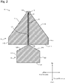
- FIG. 2 is a plan view showing the first glass antenna.
- the first glass antenna 10 includes an antenna main body that is arranged on a surface of the window glass 80 on the vehicle interior side and has a first portion 11 and a second portion 12, and also includes a track portion 13. These constituent elements are made in sheet form with a conductive material. Also, the first portion 11 is provided with a ground portion 5, and the track portion 13 is provided with the hot portion 6. The ground portion 5 and the hot portion 6 are connected to a receiver (not shown) provided inside the vehicle by a coaxial cable (not shown) . Note that, for convenience of description, the following description will be given according to a first direction shown in FIG.
- first direction is a horizontal direction and the second direction is an up-down direction in the example shown in FIG. 2
- present invention is not limited to this. These directions can be changed as appropriate while maintaining the relationship between the first direction and the second direction.
- the first portion 11 has a substantially pentagonal shape that is bilaterally symmetrical, and includes a first side 111 that extends in the first direction, a second side 112 and a third side 113 that extend orthogonally upward from two ends of the first side 111, and a fourth side 114 and a fifth side 115 that respectively extend obliquely from upper ends of the second side 112 and the third side 113.
- the fourth side 114 and the fifth side 115 extend so as to approach each other moving upward, and a rectangular protruding portion 116 is formed at a portion where the upper end portions of the fourth side 114 and the fifth side 115 are joined together.
- a slit 117 is provided that extends in the second direction from inside the protruding portion 116, that is, from a position located slightly below the upper edge of the protruding portion 116, to the first side 111. Further, the above-described track portion 13 is disposed in this slit. The track portion 13 has a linear shape and is arranged with a slight space from the inner edge of the slit 117. Also, a lower end of the track portion 13 is connected to the second portion 12.
- the length of the track portion 13 is preferably ⁇ /20 ( ⁇ represents a wavelength shortening coefficient in the window glass) or more where the wavelength of the radio waves received is ⁇ and a wavelength shortening coefficient ⁇ in a typical window glass is in a range of 0.6 to 0.7, for example.
- ground portion 5 is provided in the protruding portion 116, and the hot portion 6 is provided at the upper end of the track portion 13. Therefore, the ground portion 5 and the hot portion 6 are spaced apart from each other with the slit 117 interposed therebetween.
- the second portion 12 is arranged below the first portion 11.
- the second portion 12 has a substantially pentagonal shape (home base shape) that is bilaterally symmetrical, and includes a first side 121 that extends in the first direction, a second side 122 and a third side 123 that extend orthogonally upward from two ends of the first side 121, and a fourth side 124 and a fifth side 125 that respectively extend obliquely from upper ends of the second side 122 and the third side 123.
- the fourth side 124 and the fifth side 125 extend so as to approach each other moving upward. Further, the upper end portions of the fourth side 124 and the fifth side 125 are in contact with each other, forming an upper vertex 126.
- the lower end of the track portion 13 is connected to the upper vertex 126.
- the second portion 12 is smaller than the first portion 11, and as shown in FIG. 2 , for example, the lengths of the second portion 12 in the first direction and the second direction can be each about half of the length of the first portion 11.
- the antenna main body of the first glass antenna 10 is formed bilaterally symmetrically with respect to the reference line (a line extending along the track portion 13) that passes through the ground portion 5 and extends in the up-down direction.
- the length of the first glass antenna 10 in the first direction preferably ranges from 30 mm to 90 mm, and more preferably ranges from 40 mm to 80 mm, for example.
- the length of the first glass antenna 10 in the second direction preferably ranges from 20 mm to 80 mm, and more preferably ranges from 30 mm to 70 mm. The same applies to the second glass antenna 20.
- FIG. 3 is a plan view showing the second glass antenna.
- the second glass antenna 20 includes an antenna main body that is arranged on a surface of the window glass 80 on the vehicle interior side and has a first portion 21 and a second portion 22, and also includes a first track portion 23, a second track portion 24, and an extension portion 26. These constituent elements are made in sheet form with a conductive material. Also, the first track portion 231 is provided with a ground portion 5, and the second track portion 24 is provided with the hot portion 6. Similarly to the first glass antenna, these ground portion 5 and hot portion 6 are connected to a receiver provided inside the vehicle by a coaxial cable.
- the first portion 21 has a substantially pentagonal shape that is bilaterally symmetrical, and includes a first side 211 that extends in the first direction, a second side 212 and a third side 213 that extend orthogonally downward from two ends of the first side 211, and a fourth side 214 and a fifth side 215 that respectively extend obliquely from lower ends of the second side 212 and the third side 213.
- the fourth side 214 and the fifth side 215 extend so as to approach each other moving downward. Further, the lower end portions of the fourth side 214 and the fifth side 215 are in contact with each other, forming a lower vertex 216.
- the second portion 22 is arranged below the first portion 21, and has a shape vertically symmetrical with the first portion 21. That is, the second portion 22 has a substantially pentagonal shape that is bilaterally symmetrical, and includes a first side 221 that extends in the first direction, a second side 222 and a third side 223 that extend orthogonally upward from two ends of the first side 221, and a fourth side 224 and a fifth side 225 that respectively extend obliquely from upper ends of the second side 222 and the third side 223.
- the fourth side 224 and the fifth side 225 extend so as to approach each other moving upward. Further, the upper end portions of the fourth side 224 and the fifth side 225 are in contact with each other, forming an upper vertex 226.
- the upper vertex 226 and the lower vertex 216 of the first portion 21 are arranged with a slight gap interposed therebetween, and the first track portion 23 and the second track portion 24 are arranged in this gap.
- the first track portion 23 is arranged on the right side of the first portion 21 and has an L-shape. That is, the first track portion 23 includes a first line portion 231 that extends in the up-down direction and a second line portion 232 that extends from the lower end of the first line portion 231 leftward in the horizontal direction.
- the position of the upper end of the first line portion 231 in the up-down direction is substantially the same as the position of the first side 211 of the first portion 21.
- the position of the lower end of the first line portion 231 in the up-down direction is substantially the same as the position of the lower vertex 216 of the first portion 21. Therefore, the left end portion of the second line portion 232 is connected to the lower vertex 216.
- the second track portion 24 is also arranged on the right side of the first portion 21 and has an L-shape. That is, the second track portion 24 includes a first line portion 241 that extends in the up-down direction and a second line portion 242 that extends from the lower end of the first line portion 241 leftward in the horizontal direction.
- the first line portion 241 has substantially the same length as the first line portion 231 of the first track portion 23, and extends in parallel to the first line portion 231 on the right side of the first line portion 231 with a gap interposed therebetween.
- the second line portion 242 has substantially the same length as the second line portion 232 of the first track portion 23, and extends in parallel to the second line portion 232 on the lower side of the second line portion 232 with a gap interposed therebetween. Also, the left end portion of the second line portion 242 is connected to the upper vertex 226 of the second portion 22.
- the length of the gap interposed between the first track portion 23 and the second track portion 24 is 1 mm or less, preferably 0.5 mm or less, and more preferably 0.1 mm or less in order to improve reception performance. Note that, similarly to the first glass antenna 10, the length of the track portions 23 and 24 can be ⁇ /20.
- the upper end of the first line portion 231 of the first track portion 23 is provided with the ground portion 5
- the upper end of the first line portion 241 of the second track portion 24 is provided with the hot portion 6.
- the extension portion 26 is arranged on the left side of the first portion 21, and has an L-shape. That is, the extension portion 26 includes a first line portion 261 that extends in the up-down direction and a second line portion 262 that extends from the lower end of the first line portion 261 rightward in the horizontal direction. The upper end of the first line portion 261 is connected to an intersection of the second side 212 and the fourth side 214 of the first portion 21. Also, the right end portion of the second line portion 262 is connected to the left end portion of the first track portion 23.
- the first glass antenna 10 and the second glass antenna 20 can be formed by laminating a conductive material having conductivity on the surface of the window glass 80, such that a predetermined pattern is formed.
- a conductive material can be adopted as such a material, and examples thereof may include silver, gold, copper, platinum, and ITO (indium tin oxide).
- these antennas can be formed by, for example, printing and baking a conductive silver paste containing silver powder, glass frit and the like on the surface of the window glass 80, for example.
- a conductor that can be formed through direct deposition on the glass surface, such as ITO.
- an antenna can also be formed by cutting the foil into a predetermined shape. If a colored conductor is to be formed, in order to secure the field of view from the inside of the vehicle, an antenna can also be formed by cutting a sheet structure in which the conductor is formed as thin lines into a mesh pattern, or by printing such a sheet structure directly on the surface of the window glass, for example. Also, there is no particular limitation to the thicknesses of the glass antennas 10 and 20, and the glass antennas 10 and 20 each have a thickness of 0.01 to 50 ⁇ m, for example.
- the glass antennas 10 and 20 according to this embodiment includes two planer portions, it is possible to obtain favorable reception performance in frequency bands for both 4G and 5G. A more detailed description is given below.
- the 4G and 5G frequency bands are in a range of 600 MHz to 5 GHz. Because a conventional linear antenna can resonate only in a given range of frequencies corresponding to the segment length of the antenna cable, the receivable band can only be several hundred MHz at its widest. In view of this, by forming an assembly of antenna cables with a certain range of segment lengths, that is, by forming antenna cables in a planar shape, cable segments in which radio waves resonate over a wide band of several GHz occur in several places in the plane. Thus, favorable reception performance can be obtained.
- an outer edge has a corner portion, such as in the first portions 11 and 21 and the second portions 21 and 22 described above, cable segments in which radio waves resonate, such as a cable segment extending diagonally from this corner portion, tend to occur. Also, if the outer edge has a plurality of corner portions, radio waves tend to resonate on a cable segment connecting corner portions. Thus, it is possible to further improve reception performance. Further, because the first portions 11 and 21 and the second portions 21 and 22 have a polygonal shape, radio waves tend to also resonate on the linear sides. Thus, it is possible to further improve reception performance.
- the track portion 23 that has substantially the same length as the track portions 13, 24, and 24 can function as a part of an impedance matching element. Thus, it is possible to further improve reception performance.
- first portion 21 and the second portion 22 are symmetrical with each other, such as in the second glass antenna 20, segments in which radio waves resonate occur symmetrically. Thus, it is possible to further improve reception performance.
- a planar antenna of the present invention is constituted by a colored conductor, for example, light does not pass through the colored portion, obstructing the field of view.
- a planar antenna of the present invention is constituted by a colored conductor, for example, light does not pass through the colored portion, obstructing the field of view.
- light can partially pass through this portion, and obstruction of the field of view can be reduced. It is more preferable to use a transparent conductor because obstruction of the field of view is eliminated.
- the glass antenna can have various shapes, and the shape of the glass antenna is not limited to the above embodiment.
- (1) There is no particular limitation to the shapes of the first portions 11 and 21 and the second portions 12 and 22 of the glass antennas 10 and 20. These portions may have a polygonal shape or a circular shape, and may also have an outer edge in which straight lines and curved lines are mixed with each other.
- a portion of the outer edge of the second portion 12 in the first glass antenna 10 is constituted by a curved line, for example.
- the outer peripheral edge of each portion is constituted by a straight line and has at least one corner portion in order to improve reception performance.
- the shape of the first glass antenna 10 in FIG. 2 is an example, and as shown in FIG. 5 , the width thereof in the first direction can be reduced, and the width of the slit 117 or the track portion 13 can also be increased, for example. Also, as shown in FIG. 6 , the width of the first portion 11 can be set to two times or more the width of the second portion 12, and the width of the protruding portion 16 can be further increased.
- the two portions of the above-described first glass antenna 10 have different sizes, they may have the same size. However, according to the inventors of the present invention, it is preferable that the first portion is larger than the second portion in order to improve reception performance.
- the shape of the first portion 11 is a substantially pentagonal shape in the above-described first glass antenna 10, the shape of the first portion 11 is not limited to this and may have other shapes. As shown in FIG. 7 , the first portion 11 may have a rectangular shape, for example. The first portion 11 in this example is formed in a rectangular shape that is longer in the lateral direction than in the longitudinal direction, and the length of the first portion 11 in the lateral direction is longer than the length of the second portion 12 in the lateral direction.
- the second portion 12 can have the shape shown in FIG. 8 .
- the first portion has the shape shown in FIG. 7
- the second portion 12 has a triangular shape.
- the second portion 12 has a substantially triangular shape, and the track portion 13 is connected to the vertex of the upper portion thereof.
- the second portion 12 is provided with a plurality of triangular through-holes.
- a first triangle 1201 is formed by connecting the midpoints of the sides of the triangle that constitutes the second portion 12, forming a through-hole.
- second triangles 1202 are each formed by connecting the midpoints of the sides of the respective one of the three triangles that are formed above and to the left and right of the first triangle 1201, forming through-holes.
- third triangles 1203 are each formed by connecting the midpoints of the sides of the respective one of the three triangles that are formed above and to the left and right of the second triangle 1202, forming through-holes.
- the second portion 12 is provided with thirteen through-holes having three types of inverted triangular shapes. Note that, although the through-holes have inverted triangular shapes in this example, there is no particular limitation to the shape of the through-holes.
- the through-holes may have various shapes such as polygonal shapes, circular shapes, and irregular shapes. There is also no particular limitation to the positions of the through-holes.
- the second sides 212 and 222 and the third sides 213 and 223 in the portions 21 and 22 may incline obliquely, for example.
- an extension portion need not be provided.
- the track portions 23 and 24 may also be formed in a straight line, and there is no particular limitation to the shapes of the track portions.
- the two portions of the second glass antenna 20 have the same shape, they may have different shapes. However, according to the inventors of the present invention, in order to improve reception performance, it is preferable that the first portion and the second portion have the same size and are arranged point-symmetrically with each other. Although the vertexes of the portions 21 and 22 are preferably arranged facing each other, there is no limitation to this.
- the first portion 11 is provided with the slit 117, and the track portion 13 is arranged in this slit 117. That is, the track portion 13 is arranged inside the first portion 11.
- the track portions 23 and 24 are arranged outside the portions 21 and 22.
- the track portions 23 and 24 in the second glass antenna 20 need not extend in parallel to each other, and may be separated from each other.
- the glass antennas 10 and 20 are arranged on a window glass.
- the glass antennas 10 and 20 need only be arranged in an appropriate orientation, taking reception performance into consideration.
- the glass antenna may be turned upside down from FIG. 1 as shown in FIG. 11A , or may be tilted 90 degrees as shown in FIG. 11B , for example.
- the positions at which the glass antennas 10 and 20 are provided and they can be provided at any position on the window glass 80.
- the second glass antenna 20 shown in FIG. 10 is tilted 90 degrees such that the track portions 23 and 24 are located upward. In this manner, there is no particular limitation to the rotation angle for the second glass antenna 20.
- ground portion 5 is arranged at the vertex of the first portion 11 that is located farthest from the second portion 12 in the first glass antenna 10 of the embodiment, there is no particular limitation to the position of the ground portion 5. That is, the ground portion 5 need not be arranged at the vertex, and need only be arranged in the farthest portion such as on a side, or in the vicinity thereof, depending on the shape of the first portion 11.
- the reception performance of the glass antennas according to the examples 1 to 16 and a comparative example was examined.
- Three-dimensional electromagnetic field simulation software was used for examining reception performance.
- a glass plate was modeled, assuming a typical laminated glass in which an interlayer with a thickness of 0.76 mm was interposed between two pieces of glass with a thickness of 2.1 mm.
- the shapes and sizes of the glass antennas are shown in Table 1 below, and the model was obtained assuming that the shortening coefficient ⁇ of the glass plate was 0.61 and radio waves had a frequency of 500 MHz to 6 GHz.
- the simulation procedure (1) a vehicle, a dielectric body, an antenna, and the like were modeled and the materials were set, (2) appropriate meshes for the vehicle, the dielectric body, the antenna and the like were set, and then simulation was executed.
- the glass antenna according to the comparative example had a rectangular main body portion 71 and a linear track portion 72 that extended upward from the vicinity of an upper side of the upper side of the main body portion 71.
- a gap was formed between the main body portion 71 and the track portion 72.
- the hot portion 6 was arranged at a lower end of the track portion 72, and the ground portion 5 was arranged in a portion facing the track portion 72 on the upper side of the main portion 71.
- the examples 1 to 4 were formed as followed.
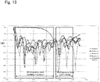
- FIG. 13 is a graph showing reception performance at a frequency of 500 MHz to 6 GHz. According to the inventors of the present invention, if a return loss of -7.4 dB or less is obtained, such antennas can withstand practical use. Based on FIG. 13 , it was found that the comparative example had a favorable return loss in the 5G frequency band, but had a considerably poor return loss in the 4G frequency band. The examples 1 to 4 substantially had favorable return losses in both 4G and 5G frequency bands .
- the length of the example 2 in the second direction was almost the same as the example 1, but the length of the example 2 in the first direction was about 2/3 of the length of the example 1 in the first direction.
- the examples 1 and 3 were different from each other mainly in the positions and the shapes of the track portions.
- the examples 1 and 3 had almost the same overall reception performances, but had high reception performance in different frequencies.
- the example 1 had high reception performance around 4 GHz in the 5G frequency band, whereas the example 3 had high reception performance around 4.5 GHz, for example.
- the examples 5 to 15 were antennas having the shape shown in FIG. 14 , and correspond to the above-described glass antenna shown in FIG. 7 .
- the antenna having the dimension shown in FIG. 14 was the antenna according to the example 5.
- the examples 6 to 15 were obtained by changing the dimensions A to D in FIG. 14 (in units of mm) and the angle E (in units of degrees).
- a B C D E Ex. 5 80 76 140 25 38 Ex. 6 70 76 140 25 38 Ex. 7 90 76 140 25 38 Ex. 8 80 66 140 25 38 Ex. 9 80 86 140 25 38 Ex. 10 80 76 120 25 38 Ex. 11 80 76 160 25 38 Ex. 12
- 80 76 140 15 38 Ex. 13 80 76 140 30 38 Ex. 14 80 76 140 25 30 Ex. 15 80 76 140 25 45
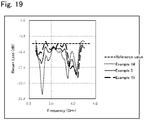
- the reception performance of the antennas was calculated in the same manner as in the examples 1 to 4. The results therefor are shown in FIGS. 15 to 19 . It was found that the glass antennas having the shapes of the examples 5 to 15 substantially had a return loss of -7.4 dB (the reference value in FIGS. 15 to 19 ) or less, and could withstand practical use.
- the example 16 was an antenna having the shape shown in FIG. 20 , and corresponds to the above-described glass antenna (the numerical values in FIG. 20 are in units of mm) shown in FIG. 8 .
- the reception performance of the antennas was calculated in the same manner as in the examples 1 to 4.
- the results therefor are shown in FIG. 21 .
- the frequency (GHz) is shown on the horizontal axis
- the return loss (dB) is shown on the vertical axis.
- the glass antennas having the shape of the example 16 had a return loss of -7.4 dB (the reference value in FIG. 21 ) described above or less in a range of 1.0 to 7.0 GHz, and could withstand practical use.
Landscapes
- Engineering & Computer Science (AREA)
- Remote Sensing (AREA)
- Details Of Aerials (AREA)
Abstract
Description
- The present invention relates to a glass antenna to be provided on a window glass of a vehicle.
- Antennas for transmitting and receiving radio waves over a wide band have a planar shape in order to resonate at various frequencies. (e.g., Patent Literature 1). Incidentally, the current automotive communication technology is shifting from fourth generation communications (4G) to fifth generation communications (5G) . In view of this, automobiles also need to have vehicle glass antennas capable of receiving radio waves in 5G frequency bands.
- Patent Literature 1:
WO 2017/018323 - However, even when 5G is introduced, communication in 4G frequency bands will also be used in combination therewith. Therefore, vehicles, which move around regardless of the 4G and 5G regions, need to be able to receive radio waves in both the 4G and 5G frequency bands. Thus, such vehicles need to be equipped with antennas that support both 4G and 5G. However, so far, glass antennas capable of receiving radio waves corresponding to both 4G and 5G frequency bands are not available, and there is demand for such glass antennas. The present invention was made to resolve this issue, and aims to provide a glass antenna capable of receiving radio waves in frequency bands supported in both 4G and 5G.
-
Aspect 1. A glass antenna to be provided on a window glass of a vehicle, the glass antenna including: - a hot portion;
- a ground portion; and
- an antenna main body connected to the hot portion and the ground portion,
- in which the glass antenna is configured to receive radio waves with a frequency band of 600 MHz to 5 GHz.
-
Aspect 2. The glass antenna according toAspect 1, in which the antenna main body includes: - a first portion that has a planar shape, and
- a second portion that is electrically connected to the first portion and has a planar shape.
-
Aspect 3. The glass antenna according toAspect 2, in which an outer edge of at least one of the first portion and the second portion has at least one corner portion. -
Aspect 4. The glass antenna according toAspect 2, in which at least one of the first portion and the second portion is formed by a polygon having linear sides. -
Aspect 5. The glass antenna according to any one ofAspects 2 to 4,
in which the ground portion is arranged in the vicinity of a portion of an outer peripheral edge of the first portion that is located farthest from the second portion. -
Aspect 6. The glass antenna according to Aspect 5, - in which, when the wavelength of the radio waves is λ and the wavelength shortening coefficient in the window glass is α,
- the distance from the hot portion to the second portion is α×λ/20 or more.
-
Aspect 7. The glass antenna according to Aspect 5 or 6,
in which the first portion is larger than the second portion. -
Aspect 8. The glass antenna according to any one ofAspects 5 to 7,
in which the first portion and the second portion are formed line symmetrically with respect to a reference line passing through the ground portion and passing through the first portion and the second portion. -
Aspect 9. The glass antenna according to any one ofAspects 2 to 4,
in which one vertex of an outer peripheral edge of the first portion and one vertex of an outer peripheral edge of the second portion are arranged so as to face each other. -
Aspect 10. The glass antenna according to Aspect 9,
in which the first portion and the second portion have a shape symmetrical with respect to a midpoint between the one vertex of the first portion and the one vertex of the second portion. -
Aspect 11. The glass antenna according to Aspect 9 or 10,
in which the hot portion and the ground portion are arranged outside the first portion and the second portion. -
Aspect 12. The glass antenna according to Aspect 11, further including: - a first track portion extending so as to connect the ground portion and the first portion to each other; and
- a second track portion extending in parallel to the first track portion so as to connect the hot portion and the second portion to each other.
-
Aspect 13. The glass antenna according to Aspect 12,
in which a gap between the first track portion and the second track portion is 1 mm or less. - A glass antenna according to the present invention is capable of receiving radio waves with frequency bands that are supported in both 4G and 5G.
-
-
FIG. 1 is a plan view of a portion of a window glass on which a glass antenna of the present invention is arranged. -
FIG. 2 is a plan view showing a first glass antenna. -
FIG. 3 is a plan view showing a second glass antenna. -
FIG. 4 is a plan view showing another example of the first glass antenna. -
FIG. 5 is a plan view showing another example of the first glass antenna. -
FIG. 6 is a plan view showing another example of the first glass antenna. -
FIG. 7 is a plan view showing another example of the first glass antenna. -
FIG. 8 is a plan view showing another example of the first glass antenna. -
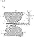
FIG. 9 is a plan view showing another example of the second glass antenna. -
FIG. 10 is a plan view showing another example of the second glass antenna. -
FIG. 11A is a plan view showing another example of the orientation of the first glass antenna. -
FIG. 11B is a plan view showing another example of the orientation of the first glass antenna. -
FIG. 11C is a plan view showing another example of the orientation of the second glass antenna. -
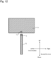
FIG. 12 is a plan view of a glass antenna according to a comparative example. -
FIG. 13 is a graph showing reception performance according to examples 1 to 4 and the comparative example. -
FIG. 14 is a plan view of a glass antenna according to an example 5. -
FIG. 15 is a graph showing reception performance according to examples 5 to 7. -
FIG. 16 is a graph showing reception performance according to examples 5, 8, and 9. -
FIG. 17 is a graph showing reception performance according to examples 5, 10, and 11. -
FIG. 18 is a graph showing reception performance according to examples 5, 12, and 13. -
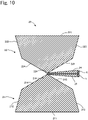
FIG. 19 is a graph showing reception performance according to examples 5, 14, and 15. -
FIG. 20 is a plan view of a glass antenna according to an example 16. -
FIG. 21 is a graph showing reception performance according to the example 16. - Hereinafter, an embodiment of a glass antenna according to the present invention will be described with reference to the drawings.
FIG. 1 is a plan view showing a window glass of a vehicle on which a first glass antenna is arranged. There is no particular limitation to a target window glass as long as it is a window glass for a vehicle, and the glass antenna can be arranged on any one of a windshield, a rear glass, a side glass, and the like. Note that two types of glass antennas, that is, afirst glass antenna 10 and asecond glass antenna 20, will be described in this embodiment. Note that, although thefirst glass antenna 10 is shown inFIG. 1 , at least one of theglass antennas window glass 80 will be first described, and then theglass antennas - First, the
window glass 80 on which theglass antennas window glass 80. Heat absorbing glass, ordinary clear glass, dark privacy glass or dark green glass, or UV green glass may be utilized as the glass plate, for example. Such a glass plate needs, however, to realize a visible light transmittance that meets safety standards of the country in which the automobile is to be used. Solar absorptivity, visible light transmittance, and the like can be adjusted to meet safety standards, for example. Hereinafter, an example of the composition of clear glass and an example of the composition of heat absorbing glass will be shown. -
- SiO2: 70 to 73 mass%
- Al2O3: 0.6 to 2.4 mass%
- CaO: 7 to 12 mass%
- MgO: 1.0 to 4.5 mass%
- R2O: 13 to 15 mass% (R represents an alkaline metal)
- The composition of heat absorbing glass can, for example, be given as a composition, based on the composition of clear glass, including total iron oxide in terms of Fe2O3 (T-Fe2O3) at a ratio of 0.4 to 1.3 mass%, CeO2 at a ratio of 0 to 2 mass%, and TiO2 at a ratio of 0 to 0.5 mass%, and in which the skeletal component (mainly SiO2 or Al2O3) of the glass is reduced by an amount equivalent to the increase in T-Fe2O3, CeO2 and TiO2.
- Note that the type of glass plate is not limited to clear glass or heat absorbing glass, and can be selected as appropriate according to the embodiment. The glass plate may be a resin window made of acrylic resin, polycarbonate resin or the like, for example.
- Also, the
window glass 80 has a curved shape as appropriate. Further, such awindow glass 80 may be a laminated glass in which an interlayer such as a resin film is sandwiched between multiple glass plates, in addition to being a single glass plate. If the window glass is constituted by a single glass plate, a glass antenna is arranged on a surface of thewindow glass 80 located on the vehicle interior side. On the other hand, if thewindow glass 80 is a laminated glass, theglass antennas glass antennas - Next, the
first glass antenna 10 will be described with reference toFIG. 2. FIG. 2 is a plan view showing the first glass antenna. Thefirst glass antenna 10 includes an antenna main body that is arranged on a surface of thewindow glass 80 on the vehicle interior side and has afirst portion 11 and asecond portion 12, and also includes atrack portion 13. These constituent elements are made in sheet form with a conductive material. Also, thefirst portion 11 is provided with aground portion 5, and thetrack portion 13 is provided with thehot portion 6. Theground portion 5 and thehot portion 6 are connected to a receiver (not shown) provided inside the vehicle by a coaxial cable (not shown) . Note that, for convenience of description, the following description will be given according to a first direction shown inFIG. 2 and a second direction that is orthogonal to the first direction. However, although the first direction is a horizontal direction and the second direction is an up-down direction in the example shown inFIG. 2 , the present invention is not limited to this. These directions can be changed as appropriate while maintaining the relationship between the first direction and the second direction. The same applies to thesecond glass antenna 20, which will be described later. - The
first portion 11 has a substantially pentagonal shape that is bilaterally symmetrical, and includes afirst side 111 that extends in the first direction, asecond side 112 and athird side 113 that extend orthogonally upward from two ends of thefirst side 111, and afourth side 114 and afifth side 115 that respectively extend obliquely from upper ends of thesecond side 112 and thethird side 113. Thefourth side 114 and thefifth side 115 extend so as to approach each other moving upward, and a rectangular protrudingportion 116 is formed at a portion where the upper end portions of thefourth side 114 and thefifth side 115 are joined together. - Also, a
slit 117 is provided that extends in the second direction from inside the protrudingportion 116, that is, from a position located slightly below the upper edge of the protrudingportion 116, to thefirst side 111. Further, the above-describedtrack portion 13 is disposed in this slit. Thetrack portion 13 has a linear shape and is arranged with a slight space from the inner edge of theslit 117. Also, a lower end of thetrack portion 13 is connected to thesecond portion 12. Note that, although there is no particular limitation to the length of thetrack portion 13, that is, the distance from thehot portion 6 to thesecond portion 12, in order to improve reception performance, the length of thetrack portion 13 is preferably α×λ/20 (α represents a wavelength shortening coefficient in the window glass) or more where the wavelength of the radio waves received is λ and a wavelength shortening coefficient α in a typical window glass is in a range of 0.6 to 0.7, for example. - The above-described
ground portion 5 is provided in the protrudingportion 116, and thehot portion 6 is provided at the upper end of thetrack portion 13. Therefore, theground portion 5 and thehot portion 6 are spaced apart from each other with theslit 117 interposed therebetween. - Next, the
second portion 12 will be described. Thesecond portion 12 is arranged below thefirst portion 11. Thesecond portion 12 has a substantially pentagonal shape (home base shape) that is bilaterally symmetrical, and includes afirst side 121 that extends in the first direction, asecond side 122 and athird side 123 that extend orthogonally upward from two ends of thefirst side 121, and afourth side 124 and afifth side 125 that respectively extend obliquely from upper ends of thesecond side 122 and thethird side 123. Thefourth side 124 and thefifth side 125 extend so as to approach each other moving upward. Further, the upper end portions of thefourth side 124 and thefifth side 125 are in contact with each other, forming anupper vertex 126. The lower end of thetrack portion 13 is connected to theupper vertex 126. - The
second portion 12 is smaller than thefirst portion 11, and as shown inFIG. 2 , for example, the lengths of thesecond portion 12 in the first direction and the second direction can be each about half of the length of thefirst portion 11. - As described above, the antenna main body of the
first glass antenna 10 is formed bilaterally symmetrically with respect to the reference line (a line extending along the track portion 13) that passes through theground portion 5 and extends in the up-down direction. - There is no particular limitation to the size of the
first glass antenna 10, and the length of thefirst glass antenna 10 in the first direction preferably ranges from 30 mm to 90 mm, and more preferably ranges from 40 mm to 80 mm, for example. On the other hand, the length of thefirst glass antenna 10 in the second direction preferably ranges from 20 mm to 80 mm, and more preferably ranges from 30 mm to 70 mm. The same applies to thesecond glass antenna 20. - Next, the
second glass antenna 20 will be described with reference toFIG. 3. FIG. 3 is a plan view showing the second glass antenna. Thesecond glass antenna 20 includes an antenna main body that is arranged on a surface of thewindow glass 80 on the vehicle interior side and has afirst portion 21 and asecond portion 22, and also includes afirst track portion 23, asecond track portion 24, and anextension portion 26. These constituent elements are made in sheet form with a conductive material. Also, thefirst track portion 231 is provided with aground portion 5, and thesecond track portion 24 is provided with thehot portion 6. Similarly to the first glass antenna, theseground portion 5 andhot portion 6 are connected to a receiver provided inside the vehicle by a coaxial cable. - The
first portion 21 has a substantially pentagonal shape that is bilaterally symmetrical, and includes afirst side 211 that extends in the first direction, asecond side 212 and athird side 213 that extend orthogonally downward from two ends of thefirst side 211, and afourth side 214 and afifth side 215 that respectively extend obliquely from lower ends of thesecond side 212 and thethird side 213. Thefourth side 214 and thefifth side 215 extend so as to approach each other moving downward. Further, the lower end portions of thefourth side 214 and thefifth side 215 are in contact with each other, forming alower vertex 216. - The
second portion 22 is arranged below thefirst portion 21, and has a shape vertically symmetrical with thefirst portion 21. That is, thesecond portion 22 has a substantially pentagonal shape that is bilaterally symmetrical, and includes afirst side 221 that extends in the first direction, asecond side 222 and athird side 223 that extend orthogonally upward from two ends of thefirst side 221, and afourth side 224 and afifth side 225 that respectively extend obliquely from upper ends of thesecond side 222 and thethird side 223. Thefourth side 224 and thefifth side 225 extend so as to approach each other moving upward. Further, the upper end portions of thefourth side 224 and thefifth side 225 are in contact with each other, forming anupper vertex 226. Theupper vertex 226 and thelower vertex 216 of thefirst portion 21 are arranged with a slight gap interposed therebetween, and thefirst track portion 23 and thesecond track portion 24 are arranged in this gap. - The
first track portion 23 is arranged on the right side of thefirst portion 21 and has an L-shape. That is, thefirst track portion 23 includes afirst line portion 231 that extends in the up-down direction and asecond line portion 232 that extends from the lower end of thefirst line portion 231 leftward in the horizontal direction. The position of the upper end of thefirst line portion 231 in the up-down direction is substantially the same as the position of thefirst side 211 of thefirst portion 21. Also, the position of the lower end of thefirst line portion 231 in the up-down direction is substantially the same as the position of thelower vertex 216 of thefirst portion 21. Therefore, the left end portion of thesecond line portion 232 is connected to thelower vertex 216. - The
second track portion 24 is also arranged on the right side of thefirst portion 21 and has an L-shape. That is, thesecond track portion 24 includes afirst line portion 241 that extends in the up-down direction and asecond line portion 242 that extends from the lower end of thefirst line portion 241 leftward in the horizontal direction. Thefirst line portion 241 has substantially the same length as thefirst line portion 231 of thefirst track portion 23, and extends in parallel to thefirst line portion 231 on the right side of thefirst line portion 231 with a gap interposed therebetween. Similarly, thesecond line portion 242 has substantially the same length as thesecond line portion 232 of thefirst track portion 23, and extends in parallel to thesecond line portion 232 on the lower side of thesecond line portion 232 with a gap interposed therebetween. Also, the left end portion of thesecond line portion 242 is connected to theupper vertex 226 of thesecond portion 22. There is no particular limitation to the length of the gap interposed between thefirst track portion 23 and thesecond track portion 24, and according to the inventors of the present invention, the length of the gap is 1 mm or less, preferably 0.5 mm or less, and more preferably 0.1 mm or less in order to improve reception performance. Note that, similarly to thefirst glass antenna 10, the length of thetrack portions - Also, the upper end of the
first line portion 231 of thefirst track portion 23 is provided with theground portion 5, and the upper end of thefirst line portion 241 of thesecond track portion 24 is provided with thehot portion 6. - The
extension portion 26 is arranged on the left side of thefirst portion 21, and has an L-shape. That is, theextension portion 26 includes afirst line portion 261 that extends in the up-down direction and asecond line portion 262 that extends from the lower end of thefirst line portion 261 rightward in the horizontal direction. The upper end of thefirst line portion 261 is connected to an intersection of thesecond side 212 and thefourth side 214 of thefirst portion 21. Also, the right end portion of thesecond line portion 262 is connected to the left end portion of thefirst track portion 23. - The
first glass antenna 10 and thesecond glass antenna 20 such as described above can be formed by laminating a conductive material having conductivity on the surface of thewindow glass 80, such that a predetermined pattern is formed. Any conductive material can be adopted as such a material, and examples thereof may include silver, gold, copper, platinum, and ITO (indium tin oxide). Specifically, these antennas can be formed by, for example, printing and baking a conductive silver paste containing silver powder, glass frit and the like on the surface of thewindow glass 80, for example. In addition, it is also possible to use a conductor that can be formed through direct deposition on the glass surface, such as ITO. If a material can be formed into the form of a foil, an antenna can also be formed by cutting the foil into a predetermined shape. If a colored conductor is to be formed, in order to secure the field of view from the inside of the vehicle, an antenna can also be formed by cutting a sheet structure in which the conductor is formed as thin lines into a mesh pattern, or by printing such a sheet structure directly on the surface of the window glass, for example. Also, there is no particular limitation to the thicknesses of theglass antennas glass antennas - As described above, because the
glass antennas - It is assumed that the 4G and 5G frequency bands are in a range of 600 MHz to 5 GHz. Because a conventional linear antenna can resonate only in a given range of frequencies corresponding to the segment length of the antenna cable, the receivable band can only be several hundred MHz at its widest. In view of this, by forming an assembly of antenna cables with a certain range of segment lengths, that is, by forming antenna cables in a planar shape, cable segments in which radio waves resonate over a wide band of several GHz occur in several places in the plane. Thus, favorable reception performance can be obtained.
- If an outer edge has a corner portion, such as in the
first portions second portions first portions second portions - When the length of the
track portions hot portion 6 is set to α×λ/20 or more, thetrack portion 23 that has substantially the same length as thetrack portions - Also, when the
first portion 21 and thesecond portion 22 are symmetrical with each other, such as in thesecond glass antenna 20, segments in which radio waves resonate occur symmetrically. Thus, it is possible to further improve reception performance. - If a planar antenna of the present invention is constituted by a colored conductor, for example, light does not pass through the colored portion, obstructing the field of view. In view of this, as a result of forming an antenna by a structure in which fine lines of the conductor are formed in a mesh pattern, light can partially pass through this portion, and obstruction of the field of view can be reduced. It is more preferable to use a transparent conductor because obstruction of the field of view is eliminated.
- Although an embodiment of the present invention has been described above, the present invention is not limited to the above embodiment, and various modifications can be made without departing from the spirit of the present invention. Note that the following variations can be combined as appropriate.
- The glass antenna can have various shapes, and the shape of the glass antenna is not limited to the above embodiment. (1) There is no particular limitation to the shapes of the
first portions second portions glass antennas FIG. 4 , a portion of the outer edge of thesecond portion 12 in thefirst glass antenna 10 is constituted by a curved line, for example. However, according to the inventors of the present invention, it is preferable that the outer peripheral edge of each portion is constituted by a straight line and has at least one corner portion in order to improve reception performance. - (2) The shape of the
first glass antenna 10 inFIG. 2 is an example, and as shown inFIG. 5 , the width thereof in the first direction can be reduced, and the width of theslit 117 or thetrack portion 13 can also be increased, for example. Also, as shown inFIG. 6 , the width of thefirst portion 11 can be set to two times or more the width of thesecond portion 12, and the width of the protrudingportion 16 can be further increased. - Although the two portions of the above-described
first glass antenna 10 have different sizes, they may have the same size. However, according to the inventors of the present invention, it is preferable that the first portion is larger than the second portion in order to improve reception performance. - Also, although the shape of the
first portion 11 is a substantially pentagonal shape in the above-describedfirst glass antenna 10, the shape of thefirst portion 11 is not limited to this and may have other shapes. As shown inFIG. 7 , thefirst portion 11 may have a rectangular shape, for example. Thefirst portion 11 in this example is formed in a rectangular shape that is longer in the lateral direction than in the longitudinal direction, and the length of thefirst portion 11 in the lateral direction is longer than the length of thesecond portion 12 in the lateral direction. - Also, there is no particular limitation to the shape of the
second portion 12, and thesecond portion 12 can have the shape shown inFIG. 8 . In this example, the first portion has the shape shown inFIG. 7 , and thesecond portion 12 has a triangular shape. More specifically, in the example shown inFIG. 8 , thesecond portion 12 has a substantially triangular shape, and thetrack portion 13 is connected to the vertex of the upper portion thereof. Also, thesecond portion 12 is provided with a plurality of triangular through-holes. Specifically, afirst triangle 1201 is formed by connecting the midpoints of the sides of the triangle that constitutes thesecond portion 12, forming a through-hole. Further, in thesecond portion 12,second triangles 1202 are each formed by connecting the midpoints of the sides of the respective one of the three triangles that are formed above and to the left and right of thefirst triangle 1201, forming through-holes. Also, in thesecond portion 12,third triangles 1203 are each formed by connecting the midpoints of the sides of the respective one of the three triangles that are formed above and to the left and right of thesecond triangle 1202, forming through-holes. In this manner, thesecond portion 12 is provided with thirteen through-holes having three types of inverted triangular shapes. Note that, although the through-holes have inverted triangular shapes in this example, there is no particular limitation to the shape of the through-holes. The through-holes may have various shapes such as polygonal shapes, circular shapes, and irregular shapes. There is also no particular limitation to the positions of the through-holes. - (3) There is also no particular limitation to the shapes of the portions of the second glass antenna, and as shown in
FIG. 9 , thesecond sides third sides portions FIG. 10 , an extension portion need not be provided. Further, thetrack portions - Although the two portions of the
second glass antenna 20 have the same shape, they may have different shapes. However, according to the inventors of the present invention, in order to improve reception performance, it is preferable that the first portion and the second portion have the same size and are arranged point-symmetrically with each other. Although the vertexes of theportions - (4) As described above, in the
first glass antenna 10, thefirst portion 11 is provided with theslit 117, and thetrack portion 13 is arranged in thisslit 117. That is, thetrack portion 13 is arranged inside thefirst portion 11. On the other hand, in thesecond glass antenna 20, thetrack portions portions track portions second glass antenna 20 need not extend in parallel to each other, and may be separated from each other. Although there is also no particular limitation to the positions of theground portion 5 and thehot portion 6, they are preferably close to each other. - (5) There is no particular limitation to the orientation in which the
glass antennas glass antennas FIG. 1 , the glass antenna may be turned upside down fromFIG. 1 as shown inFIG. 11A , or may be tilted 90 degrees as shown inFIG. 11B , for example. Further, there is no particular limitation to the positions at which theglass antennas window glass 80. Also, inFIG. 11C , thesecond glass antenna 20 shown inFIG. 10 is tilted 90 degrees such that thetrack portions second glass antenna 20. - (6) Although the
ground portion 5 is arranged at the vertex of thefirst portion 11 that is located farthest from thesecond portion 12 in thefirst glass antenna 10 of the embodiment, there is no particular limitation to the position of theground portion 5. That is, theground portion 5 need not be arranged at the vertex, and need only be arranged in the farthest portion such as on a side, or in the vicinity thereof, depending on the shape of thefirst portion 11. - The following describes examples of the present invention. However, the present invention is not limited to the following examples.
- Hereinafter, the reception performance of the glass antennas according to the examples 1 to 16 and a comparative example was examined. Three-dimensional electromagnetic field simulation software was used for examining reception performance. In this simulation, a glass plate was modeled, assuming a typical laminated glass in which an interlayer with a thickness of 0.76 mm was interposed between two pieces of glass with a thickness of 2.1 mm. Also, the shapes and sizes of the glass antennas are shown in Table 1 below, and the model was obtained assuming that the shortening coefficient α of the glass plate was 0.61 and radio waves had a frequency of 500 MHz to 6 GHz. As the simulation procedure, (1) a vehicle, a dielectric body, an antenna, and the like were modeled and the materials were set, (2) appropriate meshes for the vehicle, the dielectric body, the antenna and the like were set, and then simulation was executed.
- As shown in
FIG. 12 , the glass antenna according to the comparative example had a rectangularmain body portion 71 and alinear track portion 72 that extended upward from the vicinity of an upper side of the upper side of themain body portion 71. A gap was formed between themain body portion 71 and thetrack portion 72. Also, thehot portion 6 was arranged at a lower end of thetrack portion 72, and theground portion 5 was arranged in a portion facing thetrack portion 72 on the upper side of themain portion 71. Also, the examples 1 to 4 were formed as followed.[Table 1] Ex. 1 Ex. 2 Ex. 3 Ex. 4 Comp. Ex. Shape similar to that in FIG. 2 similar to that in FIG. 4 similar to that in FIG. 3 similar to that in FIG. 6 similar to that in FIG. 10 Length in First Direction 120 mm 78 mm 85 mm 67 mm 30 mm Length in Second Direction 155 m 141 mm 140 mm 127 mm 33 mm - When simulation was performed using the examples 1 to 4 and the comparative example configured as described above, the results shown in
FIG. 13 were obtained.FIG. 13 is a graph showing reception performance at a frequency of 500 MHz to 6 GHz. According to the inventors of the present invention, if a return loss of -7.4 dB or less is obtained, such antennas can withstand practical use. Based onFIG. 13 , it was found that the comparative example had a favorable return loss in the 5G frequency band, but had a considerably poor return loss in the 4G frequency band. The examples 1 to 4 substantially had favorable return losses in both 4G and 5G frequency bands . Thus, it was found that, when two planar portions are provided as in the examples 1 to 4, a favorable return loss can be obtained in both 4G and 5G frequency bands. On the other hand, with the shape of the comparative example as shown inFIG. 12 , the resonance frequency has a certain peak, and thus favorable resonance characteristics cannot be obtained over a wide band. - Comparing the examples 1 and 2, the length of the example 2 in the second direction was almost the same as the example 1, but the length of the example 2 in the first direction was about 2/3 of the length of the example 1 in the first direction. However, there was little difference in the reception performance due to this difference in size. Also, comparing the example 1 and 3, the examples 1 and 3 were different from each other mainly in the positions and the shapes of the track portions. As a result, the examples 1 and 3 had almost the same overall reception performances, but had high reception performance in different frequencies. The example 1 had high reception performance around 4 GHz in the 5G frequency band, whereas the example 3 had high reception performance around 4.5 GHz, for example. Also, comparing the examples 1 and 4, it was found that the lengths of the example 4 in the first direction and the second direction were shorter than that of the example 1, and thus the overall reception performance of the example 4 was lower than that of the example 1 in both the 4G and 5G frequency bands.
- Next, the examples 5 to 15 were examined. The examples 5 to 15 were antennas having the shape shown in
FIG. 14 , and correspond to the above-described glass antenna shown inFIG. 7 . The antenna having the dimension shown inFIG. 14 was the antenna according to the example 5. As shown in Table 2 below, the examples 6 to 15 were obtained by changing the dimensions A to D inFIG. 14 (in units of mm) and the angle E (in units of degrees).[Table 2] A B C D E Ex. 5 80 76 140 25 38 Ex. 6 70 76 140 25 38 Ex. 7 90 76 140 25 38 Ex. 8 80 66 140 25 38 Ex. 9 80 86 140 25 38 Ex. 10 80 76 120 25 38 Ex. 11 80 76 160 25 38 Ex. 12 80 76 140 15 38 Ex. 13 80 76 140 30 38 Ex. 14 80 76 140 25 30 Ex. 15 80 76 140 25 45 - For the examples 5 to 15, the reception performance of the antennas was calculated in the same manner as in the examples 1 to 4. The results therefor are shown in
FIGS. 15 to 19 . It was found that the glass antennas having the shapes of the examples 5 to 15 substantially had a return loss of -7.4 dB (the reference value inFIGS. 15 to 19 ) or less, and could withstand practical use. - Then, the example 16 was examined. The example 16 was an antenna having the shape shown in
FIG. 20 , and corresponds to the above-described glass antenna (the numerical values inFIG. 20 are in units of mm) shown inFIG. 8 . For the example 16, the reception performance of the antennas was calculated in the same manner as in the examples 1 to 4. The results therefor are shown inFIG. 21 . InFIG. 21 , the frequency (GHz) is shown on the horizontal axis, and the return loss (dB) is shown on the vertical axis. As shown inFIG. 21 , it was found that the glass antennas having the shape of the example 16 had a return loss of -7.4 dB (the reference value inFIG. 21 ) described above or less in a range of 1.0 to 7.0 GHz, and could withstand practical use. -
- 11, 21
- First portion
- 12, 22
- Second portion
- 13
- Track portion
- 23
- First track portion
- 24
- Second track portion
- 5
- Ground portion
- 6
- Hot portion
- 10, 20
- Glass antenna
- 80
- Window glass
Claims (13)
- A glass antenna to be provided on a window glass of a vehicle, the glass antenna comprising:a hot portion;a ground portion; andan antenna main body connected to the hot portion and the ground portion,wherein the glass antenna is configured to receive radio waves with a frequency band of 600 MHz to 5 GHz.
- The glass antenna according to claim 1,
wherein the antenna main body includes:a first portion that has a planar shape and is electrically connected to the ground portion, anda second portion that is electrically connected to the hot portion and has a planar shape. - The glass antenna according to claim 2,
wherein an outer edge of at least one of the first portion and the second portion has at least one corner portion. - The glass antenna according to claim 2,
wherein at least one of the first portion and the second portion is formed by a polygon having linear sides. - The glass antenna according to any one of claims 2 to 4,
wherein the ground portion is arranged in a vicinity of a portion of an outer peripheral edge of the first portion that is located farthest from the second portion. - The glass antenna according to claim 5,wherein, when the wavelength of the radio waves is λ and a wavelength shortening coefficient in the window glass is α,the distance from the hot portion to the second portion is α×λ/20 or more.
- The glass antenna according to claim 5 or 6,
wherein the first portion is larger than the second portion. - The glass antenna according to any one of claims 5 to 7,
wherein the first portion and the second portion are formed line-symmetrically with respect to a reference line passing through the ground portion and passing through the first portion and the second portion. - The glass antenna according to any one of claims 2 to 4,
wherein one vertex of an outer peripheral edge of the first portion and one vertex of an outer peripheral edge of the second portion are arranged so as to face each other. - The glass antenna according to claim 9,
wherein the first portion and the second portion have a shape symmetrical with respect to a midpoint between the one vertex of the first portion and the one vertex of the second portion. - The glass antenna according to claim 9 or 10,
wherein the hot portion and the ground portion are arranged outside the first portion and the second portion. - The glass antenna according to claim 11, further comprising:a first track portion extending so as to connect the ground portion and the first portion to each other; anda second track portion extending in parallel to the first track portion so as to connect the hot portion and the second portion to each other.
- The glass antenna according to claim 12,
wherein a gap between the first track portion and the second track portion is 1 mm or less.
Applications Claiming Priority (2)
| Application Number | Priority Date | Filing Date | Title |
|---|---|---|---|
| JP2020031053 | 2020-02-26 | ||
| PCT/JP2021/007052 WO2021172411A1 (en) | 2020-02-26 | 2021-02-25 | Glass antenna |
Publications (2)
| Publication Number | Publication Date |
|---|---|
| EP4113739A1 true EP4113739A1 (en) | 2023-01-04 |
| EP4113739A4 EP4113739A4 (en) | 2024-03-20 |
Family
ID=77490204
Family Applications (1)
| Application Number | Title | Priority Date | Filing Date |
|---|---|---|---|
| EP21761651.5A Pending EP4113739A4 (en) | 2020-02-26 | 2021-02-25 | Glass antenna |
Country Status (5)
| Country | Link |
|---|---|
| US (1) | US20230098170A1 (en) |
| EP (1) | EP4113739A4 (en) |
| JP (1) | JP7692400B2 (en) |
| CN (1) | CN115152091A (en) |
| WO (1) | WO2021172411A1 (en) |
Families Citing this family (4)
| Publication number | Priority date | Publication date | Assignee | Title |
|---|---|---|---|---|
| EP3900195A1 (en) * | 2018-12-18 | 2021-10-27 | Snap Inc. | Adaptive eyewear antenna |
| WO2021148051A1 (en) * | 2020-01-20 | 2021-07-29 | 展讯通信(上海)有限公司 | Broadband external antenna and wireless communication device |
| WO2024184053A1 (en) | 2023-03-03 | 2024-09-12 | Agc Glass Europe | An antenna glazing comprising multiple antennas |
| CN118783094A (en) * | 2023-04-03 | 2024-10-15 | 华为技术有限公司 | Antenna device, antenna assembly and vehicle |
Family Cites Families (19)
| Publication number | Priority date | Publication date | Assignee | Title |
|---|---|---|---|---|
| JPH08213820A (en) * | 1995-02-06 | 1996-08-20 | Nippon Sheet Glass Co Ltd | Glass antenna device for car phone |
| JP3273463B2 (en) * | 1995-09-27 | 2002-04-08 | 株式会社エヌ・ティ・ティ・ドコモ | Broadband antenna device using semicircular radiating plate |
| KR100669262B1 (en) * | 2004-03-31 | 2007-01-15 | 학교법인 한국정보통신학원 | Wideband CPU Antenna Using Impedance Conversion |
| JP2007174513A (en) * | 2005-12-26 | 2007-07-05 | Asahi Glass Co Ltd | High frequency glass antenna for automobile |
| CN101188324A (en) * | 2006-10-20 | 2008-05-28 | 株式会社藤仓 | transparent antenna |
| US7498993B1 (en) * | 2007-10-18 | 2009-03-03 | Agc Automotive Americas R&D Inc. | Multi-band cellular antenna |
| JP4281023B1 (en) | 2008-02-18 | 2009-06-17 | 日本電気株式会社 | Wideband antenna and wear and belongings using it |
| JP5115359B2 (en) * | 2008-06-25 | 2013-01-09 | 旭硝子株式会社 | Glass antenna for vehicle and window glass plate for vehicle |
| CN101834343B (en) * | 2009-03-13 | 2014-03-05 | 深圳富泰宏精密工业有限公司 | Ultra-wide band antenna and wireless communication device using same |
| JP5499810B2 (en) * | 2010-03-19 | 2014-05-21 | 旭硝子株式会社 | Glass antenna for vehicle and window glass for vehicle |
| JP5631238B2 (en) * | 2011-02-23 | 2014-11-26 | 旭硝子株式会社 | Glass antenna and window glass, and antenna device including them |
| JP6251476B2 (en) * | 2012-12-20 | 2017-12-20 | セントラル硝子株式会社 | Glass antenna for vehicles |
| AU2015353606B2 (en) * | 2014-11-25 | 2020-05-21 | View, Inc. | Window antennas |
| EP3327861B1 (en) | 2015-07-24 | 2021-10-13 | AGC Inc. | Glass antenna and vehicle window glass provided with glass antenna |
| JP6601312B2 (en) * | 2015-10-30 | 2019-11-06 | Agc株式会社 | GLASS ANTENNA FOR VEHICLE AND BACK WINDOW GLASS HAVING THE GLASS ANTENNA FOR VEHICLE |
| US10530036B2 (en) * | 2016-05-06 | 2020-01-07 | Gm Global Technology Operations, Llc | Dualband flexible antenna with segmented surface treatment |
| US10707554B2 (en) * | 2016-05-06 | 2020-07-07 | GM Global Technology Operations LLC | Wideband transparent elliptical antenna applique for attachment to glass |
| DE112019000636B4 (en) * | 2018-02-02 | 2025-10-16 | AGC Inc. | Antenna device, window pane for a vehicle and window pane structure |
| US11721880B2 (en) * | 2018-03-30 | 2023-08-08 | Agc Glass Europe | Laminated glazing panel having an antenna |
-
2021
- 2021-02-25 WO PCT/JP2021/007052 patent/WO2021172411A1/en not_active Ceased
- 2021-02-25 JP JP2022503679A patent/JP7692400B2/en active Active
- 2021-02-25 US US17/802,204 patent/US20230098170A1/en not_active Abandoned
- 2021-02-25 CN CN202180017201.0A patent/CN115152091A/en active Pending
- 2021-02-25 EP EP21761651.5A patent/EP4113739A4/en active Pending
Also Published As
| Publication number | Publication date |
|---|---|
| JP7692400B2 (en) | 2025-06-13 |
| CN115152091A (en) | 2022-10-04 |
| EP4113739A4 (en) | 2024-03-20 |
| JPWO2021172411A1 (en) | 2021-09-02 |
| US20230098170A1 (en) | 2023-03-30 |
| WO2021172411A1 (en) | 2021-09-02 |
Similar Documents
| Publication | Publication Date | Title |
|---|---|---|
| US20230098170A1 (en) | Glass antenna | |
| CN112771719B (en) | Antenna system | |
| US7106256B2 (en) | Antenna device | |
| EP1616368B1 (en) | Antenna system for a motor vehicle | |
| US20050116873A1 (en) | Notched-fed antenna | |
| KR20070103689A (en) | High Frequency Glass Antenna for Automobile and Rear Window Panel for Automobile | |
| US20080158075A1 (en) | Multi-Band Loop Antenna | |
| JP2022130499A (en) | Window glass for vehicles and glass antenna for DAB | |
| WO2004051869A2 (en) | Radio transmission region in metallic panel | |
| JP2011501567A (en) | Multiband cellular antenna | |
| EP4730564A1 (en) | Artificial dielectric material, lens unit and manufacturing method therefor, and lens antenna | |
| CN111541018B (en) | High-gain steep filtering fusion duplex integrated antenna | |
| CN209822857U (en) | Novel tightly-fed broadband dual-polarization butterfly-shaped oscillator | |
| KR20050056871A (en) | Planar antenna | |
| EP3570370B1 (en) | Window glass | |
| CN119495930A (en) | A wide-band common-aperture base station antenna array based on a composite wave-transmitting structure | |
| EP3767746A1 (en) | Rear glass | |
| CN116799498A (en) | Butterfly balun fed dual polarization crossed dipole antenna | |
| CN116034518B (en) | Antenna structure and electronic equipment | |
| JP2022117929A (en) | Vehicle window glass and vehicle window glass device | |
| JP2620456B2 (en) | Radio wave transmitting heat reflecting glass for vehicles | |
| CN119275555B (en) | Low profile dual polarized magneto-electric dipole antenna implemented in standard multilayer PCB technology | |
| CN209249706U (en) | Broadband dual-frequency common reflector array | |
| CN118539165A (en) | Glass Antenna and Vehicle | |
| JP2021064942A (en) | Glass antenna |
Legal Events
| Date | Code | Title | Description |
|---|---|---|---|
| STAA | Information on the status of an ep patent application or granted ep patent |
Free format text: STATUS: THE INTERNATIONAL PUBLICATION HAS BEEN MADE |
|
| PUAI | Public reference made under article 153(3) epc to a published international application that has entered the european phase |
Free format text: ORIGINAL CODE: 0009012 |
|
| STAA | Information on the status of an ep patent application or granted ep patent |
Free format text: STATUS: REQUEST FOR EXAMINATION WAS MADE |
|
| 17P | Request for examination filed |
Effective date: 20220831 |
|
| AK | Designated contracting states |
Kind code of ref document: A1 Designated state(s): AL AT BE BG CH CY CZ DE DK EE ES FI FR GB GR HR HU IE IS IT LI LT LU LV MC MK MT NL NO PL PT RO RS SE SI SK SM TR |
|
| DAV | Request for validation of the european patent (deleted) | ||
| DAX | Request for extension of the european patent (deleted) | ||
| REG | Reference to a national code |
Ref country code: DE Ref legal event code: R079 Free format text: PREVIOUS MAIN CLASS: H01Q0001320000 Ipc: H01Q0001120000 |
|
| A4 | Supplementary search report drawn up and despatched |
Effective date: 20240220 |
|
| RIC1 | Information provided on ipc code assigned before grant |
Ipc: H01Q 9/40 20060101ALI20240214BHEP Ipc: H01Q 9/06 20060101ALI20240214BHEP Ipc: H01Q 5/25 20150101ALI20240214BHEP Ipc: H01Q 1/38 20060101ALI20240214BHEP Ipc: H01Q 1/32 20060101ALI20240214BHEP Ipc: H01Q 1/12 20060101AFI20240214BHEP |