EP4113715A1 - Battery module - Google Patents
Battery module Download PDFInfo
- Publication number
- EP4113715A1 EP4113715A1 EP21759716.0A EP21759716A EP4113715A1 EP 4113715 A1 EP4113715 A1 EP 4113715A1 EP 21759716 A EP21759716 A EP 21759716A EP 4113715 A1 EP4113715 A1 EP 4113715A1
- Authority
- EP
- European Patent Office
- Prior art keywords
- battery cells
- battery
- portions
- stacked
- pair
- Prior art date
- Legal status (The legal status is an assumption and is not a legal conclusion. Google has not performed a legal analysis and makes no representation as to the accuracy of the status listed.)
- Pending
Links
- 239000011347 resin Substances 0.000 claims description 5
- 229920005989 resin Polymers 0.000 claims description 5
- 238000005192 partition Methods 0.000 description 24
- 239000008151 electrolyte solution Substances 0.000 description 8
- 238000005516 engineering process Methods 0.000 description 8
- 239000000463 material Substances 0.000 description 6
- 125000006850 spacer group Chemical group 0.000 description 6
- 230000015556 catabolic process Effects 0.000 description 4
- 210000000078 claw Anatomy 0.000 description 4
- 238000006731 degradation reaction Methods 0.000 description 4
- 238000006073 displacement reaction Methods 0.000 description 4
- 229910001416 lithium ion Inorganic materials 0.000 description 4
- HBBGRARXTFLTSG-UHFFFAOYSA-N Lithium ion Chemical compound [Li+] HBBGRARXTFLTSG-UHFFFAOYSA-N 0.000 description 3
- 229910052782 aluminium Inorganic materials 0.000 description 3
- XAGFODPZIPBFFR-UHFFFAOYSA-N aluminium Chemical compound [Al] XAGFODPZIPBFFR-UHFFFAOYSA-N 0.000 description 3
- 230000008878 coupling Effects 0.000 description 3
- 238000010168 coupling process Methods 0.000 description 3
- 238000005859 coupling reaction Methods 0.000 description 3
- 238000010586 diagram Methods 0.000 description 3
- 229910000838 Al alloy Inorganic materials 0.000 description 2
- 238000005452 bending Methods 0.000 description 2
- 230000005540 biological transmission Effects 0.000 description 2
- 238000000034 method Methods 0.000 description 2
- -1 polypropylene Polymers 0.000 description 2
- 230000005483 Hooke's law Effects 0.000 description 1
- 239000004743 Polypropylene Substances 0.000 description 1
- 239000011247 coating layer Substances 0.000 description 1
- 230000000994 depressogenic effect Effects 0.000 description 1
- 230000000694 effects Effects 0.000 description 1
- 239000000945 filler Substances 0.000 description 1
- 239000006260 foam Substances 0.000 description 1
- 230000012447 hatching Effects 0.000 description 1
- 239000012212 insulator Substances 0.000 description 1
- 229910052751 metal Inorganic materials 0.000 description 1
- 239000002184 metal Substances 0.000 description 1
- 229920001707 polybutylene terephthalate Polymers 0.000 description 1
- 229920000515 polycarbonate Polymers 0.000 description 1
- 239000004417 polycarbonate Substances 0.000 description 1
- 229920001155 polypropylene Polymers 0.000 description 1
- 239000000243 solution Substances 0.000 description 1
- 238000000638 solvent extraction Methods 0.000 description 1
- 238000004804 winding Methods 0.000 description 1
Images


Classifications
-
- H—ELECTRICITY
- H01—ELECTRIC ELEMENTS
- H01M—PROCESSES OR MEANS, e.g. BATTERIES, FOR THE DIRECT CONVERSION OF CHEMICAL ENERGY INTO ELECTRICAL ENERGY
- H01M50/00—Constructional details or processes of manufacture of the non-active parts of electrochemical cells other than fuel cells, e.g. hybrid cells
- H01M50/20—Mountings; Secondary casings or frames; Racks, modules or packs; Suspension devices; Shock absorbers; Transport or carrying devices; Holders
- H01M50/289—Mountings; Secondary casings or frames; Racks, modules or packs; Suspension devices; Shock absorbers; Transport or carrying devices; Holders characterised by spacing elements or positioning means within frames, racks or packs
- H01M50/291—Mountings; Secondary casings or frames; Racks, modules or packs; Suspension devices; Shock absorbers; Transport or carrying devices; Holders characterised by spacing elements or positioning means within frames, racks or packs characterised by their shape
-
- H—ELECTRICITY
- H01—ELECTRIC ELEMENTS
- H01M—PROCESSES OR MEANS, e.g. BATTERIES, FOR THE DIRECT CONVERSION OF CHEMICAL ENERGY INTO ELECTRICAL ENERGY
- H01M50/00—Constructional details or processes of manufacture of the non-active parts of electrochemical cells other than fuel cells, e.g. hybrid cells
- H01M50/10—Primary casings; Jackets or wrappings
- H01M50/102—Primary casings; Jackets or wrappings characterised by their shape or physical structure
- H01M50/103—Primary casings; Jackets or wrappings characterised by their shape or physical structure prismatic or rectangular
-
- H—ELECTRICITY
- H01—ELECTRIC ELEMENTS
- H01M—PROCESSES OR MEANS, e.g. BATTERIES, FOR THE DIRECT CONVERSION OF CHEMICAL ENERGY INTO ELECTRICAL ENERGY
- H01M50/00—Constructional details or processes of manufacture of the non-active parts of electrochemical cells other than fuel cells, e.g. hybrid cells
- H01M50/20—Mountings; Secondary casings or frames; Racks, modules or packs; Suspension devices; Shock absorbers; Transport or carrying devices; Holders
- H01M50/204—Racks, modules or packs for multiple batteries or multiple cells
- H01M50/207—Racks, modules or packs for multiple batteries or multiple cells characterised by their shape
- H01M50/209—Racks, modules or packs for multiple batteries or multiple cells characterised by their shape adapted for prismatic or rectangular cells
-
- H—ELECTRICITY
- H01—ELECTRIC ELEMENTS
- H01M—PROCESSES OR MEANS, e.g. BATTERIES, FOR THE DIRECT CONVERSION OF CHEMICAL ENERGY INTO ELECTRICAL ENERGY
- H01M50/00—Constructional details or processes of manufacture of the non-active parts of electrochemical cells other than fuel cells, e.g. hybrid cells
- H01M50/20—Mountings; Secondary casings or frames; Racks, modules or packs; Suspension devices; Shock absorbers; Transport or carrying devices; Holders
- H01M50/218—Mountings; Secondary casings or frames; Racks, modules or packs; Suspension devices; Shock absorbers; Transport or carrying devices; Holders characterised by the material
- H01M50/22—Mountings; Secondary casings or frames; Racks, modules or packs; Suspension devices; Shock absorbers; Transport or carrying devices; Holders characterised by the material of the casings or racks
- H01M50/227—Organic material
-
- H—ELECTRICITY
- H01—ELECTRIC ELEMENTS
- H01M—PROCESSES OR MEANS, e.g. BATTERIES, FOR THE DIRECT CONVERSION OF CHEMICAL ENERGY INTO ELECTRICAL ENERGY
- H01M50/00—Constructional details or processes of manufacture of the non-active parts of electrochemical cells other than fuel cells, e.g. hybrid cells
- H01M50/20—Mountings; Secondary casings or frames; Racks, modules or packs; Suspension devices; Shock absorbers; Transport or carrying devices; Holders
- H01M50/233—Mountings; Secondary casings or frames; Racks, modules or packs; Suspension devices; Shock absorbers; Transport or carrying devices; Holders characterised by physical properties of casings or racks, e.g. dimensions
- H01M50/242—Mountings; Secondary casings or frames; Racks, modules or packs; Suspension devices; Shock absorbers; Transport or carrying devices; Holders characterised by physical properties of casings or racks, e.g. dimensions adapted for protecting batteries against vibrations, collision impact or swelling
-
- H—ELECTRICITY
- H01—ELECTRIC ELEMENTS
- H01M—PROCESSES OR MEANS, e.g. BATTERIES, FOR THE DIRECT CONVERSION OF CHEMICAL ENERGY INTO ELECTRICAL ENERGY
- H01M50/00—Constructional details or processes of manufacture of the non-active parts of electrochemical cells other than fuel cells, e.g. hybrid cells
- H01M50/20—Mountings; Secondary casings or frames; Racks, modules or packs; Suspension devices; Shock absorbers; Transport or carrying devices; Holders
- H01M50/249—Mountings; Secondary casings or frames; Racks, modules or packs; Suspension devices; Shock absorbers; Transport or carrying devices; Holders specially adapted for aircraft or vehicles, e.g. cars or trains
-
- H—ELECTRICITY
- H01—ELECTRIC ELEMENTS
- H01M—PROCESSES OR MEANS, e.g. BATTERIES, FOR THE DIRECT CONVERSION OF CHEMICAL ENERGY INTO ELECTRICAL ENERGY
- H01M50/00—Constructional details or processes of manufacture of the non-active parts of electrochemical cells other than fuel cells, e.g. hybrid cells
- H01M50/20—Mountings; Secondary casings or frames; Racks, modules or packs; Suspension devices; Shock absorbers; Transport or carrying devices; Holders
- H01M50/262—Mountings; Secondary casings or frames; Racks, modules or packs; Suspension devices; Shock absorbers; Transport or carrying devices; Holders with fastening means, e.g. locks
- H01M50/264—Mountings; Secondary casings or frames; Racks, modules or packs; Suspension devices; Shock absorbers; Transport or carrying devices; Holders with fastening means, e.g. locks for cells or batteries, e.g. straps, tie rods or peripheral frames
-
- H—ELECTRICITY
- H01—ELECTRIC ELEMENTS
- H01M—PROCESSES OR MEANS, e.g. BATTERIES, FOR THE DIRECT CONVERSION OF CHEMICAL ENERGY INTO ELECTRICAL ENERGY
- H01M50/00—Constructional details or processes of manufacture of the non-active parts of electrochemical cells other than fuel cells, e.g. hybrid cells
- H01M50/20—Mountings; Secondary casings or frames; Racks, modules or packs; Suspension devices; Shock absorbers; Transport or carrying devices; Holders
- H01M50/289—Mountings; Secondary casings or frames; Racks, modules or packs; Suspension devices; Shock absorbers; Transport or carrying devices; Holders characterised by spacing elements or positioning means within frames, racks or packs
- H01M50/293—Mountings; Secondary casings or frames; Racks, modules or packs; Suspension devices; Shock absorbers; Transport or carrying devices; Holders characterised by spacing elements or positioning means within frames, racks or packs characterised by the material
-
- B—PERFORMING OPERATIONS; TRANSPORTING
- B60—VEHICLES IN GENERAL
- B60L—PROPULSION OF ELECTRICALLY-PROPELLED VEHICLES; SUPPLYING ELECTRIC POWER FOR AUXILIARY EQUIPMENT OF ELECTRICALLY-PROPELLED VEHICLES; ELECTRODYNAMIC BRAKE SYSTEMS FOR VEHICLES IN GENERAL; MAGNETIC SUSPENSION OR LEVITATION FOR VEHICLES; MONITORING OPERATING VARIABLES OF ELECTRICALLY-PROPELLED VEHICLES; ELECTRIC SAFETY DEVICES FOR ELECTRICALLY-PROPELLED VEHICLES
- B60L50/00—Electric propulsion with power supplied within the vehicle
- B60L50/50—Electric propulsion with power supplied within the vehicle using propulsion power supplied by batteries or fuel cells
- B60L50/60—Electric propulsion with power supplied within the vehicle using propulsion power supplied by batteries or fuel cells using power supplied by batteries
- B60L50/64—Constructional details of batteries specially adapted for electric vehicles
-
- H—ELECTRICITY
- H01—ELECTRIC ELEMENTS
- H01M—PROCESSES OR MEANS, e.g. BATTERIES, FOR THE DIRECT CONVERSION OF CHEMICAL ENERGY INTO ELECTRICAL ENERGY
- H01M2220/00—Batteries for particular applications
- H01M2220/20—Batteries in motive systems, e.g. vehicle, ship, plane
-
- Y—GENERAL TAGGING OF NEW TECHNOLOGICAL DEVELOPMENTS; GENERAL TAGGING OF CROSS-SECTIONAL TECHNOLOGIES SPANNING OVER SEVERAL SECTIONS OF THE IPC; TECHNICAL SUBJECTS COVERED BY FORMER USPC CROSS-REFERENCE ART COLLECTIONS [XRACs] AND DIGESTS
- Y02—TECHNOLOGIES OR APPLICATIONS FOR MITIGATION OR ADAPTATION AGAINST CLIMATE CHANGE
- Y02E—REDUCTION OF GREENHOUSE GAS [GHG] EMISSIONS, RELATED TO ENERGY GENERATION, TRANSMISSION OR DISTRIBUTION
- Y02E60/00—Enabling technologies; Technologies with a potential or indirect contribution to GHG emissions mitigation
- Y02E60/10—Energy storage using batteries
Definitions
- the technology disclosed herein belongs to a technical field regarding a battery module.
- Such a vehicle has a battery module that stores electric power to be supplied to a motor.
- Many of battery modules provided in vehicles are formed by stacking a plurality of rectangular parallelepiped battery cells.
- the battery module described in patent document 1 includes a cell stacked body in which a plurality of battery cells are stacked in a first direction with insulators sandwiched therebetween, a pair of end plates disposed on both side surfaces in the first direction of the cell stacked body, and a pair of side frames disposed on both side surfaces in the second direction orthogonal to the first direction of the cell stacked body, in which each of the side frames has a front flange portion that extends along the front end plate so as to close to each other and a rear flange portion that extends along the rear end plate so as to close to each other, the front flange portion is fastened to the front end plate and the rear flange portion is fastened to the rear end plate, and the battery cells are allowed to expand in the first direction due to degradation according to changes in the angles of the front flange portion and the rear flange portion.
- the battery module described in patent document 2 includes battery cells, a case that houses the battery cells, a foamed coating layer sandwiched between the outer surface of the battery cells and the inner surface of the case, in which partition plates extending from the case are disposed at the positions corresponding to the outer circumference portions of the surface portions in the stacking direction of the battery cells and clearances are present in the portions corresponding to the centers of the surface portions of the battery cells.
- the spring force of the flange becomes strong particularly when the battery cells expand, and the constraint force in the stacking direction becomes high.
- the constraint force in the stacking direction is strong, the electrolyte solution repeatedly sinks into and exudes from the electrodes, thereby increasing the uneven concentration of the electrolyte solution. This locally increases the internal resistance and degrades the battery cells.
- the constraint force in the stacking direction is substantially zero in the central portions of the battery cells when there is a clearance between battery cells as in the battery module described in patent document 2.
- the constraint force in the stacking direction is too weak, the distance between electrodes becomes uneven. This locally increases the internal resistance.
- connection portions between the electrode body and the terminals are loaded and damaged, thereby reducing the service life of the battery cell.
- the technology disclosed herein easily extends the service life of the battery cells by setting the constraint force in the stacking direction on the battery cells to an appropriate value in a battery module in which a plurality of battery cells are stacked.
- the inventors of the present application have disposed soft members in a portion in the battery cells that are likely to expand and constrained the battery cells with a low load.
- the technology disclosed herein has a structure including battery cells, each of the battery cells including a pair of first surface portions facing each other in the first direction, a pair of second surface portions facing each other in a second direction orthogonal to the first direction, a pair of third surface portions facing each other in a third direction orthogonal to the first direction and the second direction, and an electrode body in which a positive electrode plate and a negative electrode plate are arranged in the first direction in a space formed by the first surface portions, the second surface portions, and the third surface portions; an outer shell portion that houses the stacked battery cells; elastic members, each of which is provided between the battery cells adjacent to each other in the first direction; and fixed portions that fix the battery cells to the outer shell portion, in which the elastic members are disposed so as to cover central portions of the first surface portions, and the fixed portions are disposed so as to cover outer circumference portions of the first surface portions.
- the central portions of the first surface portions of the battery cells are likely to expand and this expansion makes the constraint force in the stacking direction on the battery cells high.
- the elastic members are disposed between the adjacent battery cells in the first direction, so the elastic members deform so as to shrink according to the expansion of the central portions of the first surface portions. This can suppress an increase in loads on the battery cells due to the expansion as compared with the case in which, for example, the central portions of the first surface portions of the battery cells are covered with non-elastic members. As a result, the battery cells remain constrained with a low load.
- the fixed portions By disposing the fixed portions in the outer circumference portions of the battery cells, which are less likely to expand, it is possible to suppress an increase in displacement of the battery cells due to vibration and the fixed portions can also prevent an increase in the constraint force in the stacking direction on the battery cells. Since this prevents uneven distance between the electrodes and uneven concentration of the electrolyte solution while fixing the battery cells, an increase in the internal resistance of the battery cells is suppressed, thereby extending the service life of the battery cells.
- the elastic members may have a size that covers the entire electrode body as seen in the first direction.
- the elastic members has a size that covers the entire electrode body, so the elastic members can appropriately constrain the portion in which the electrode body is provided. Since a load is applied to the entire electrode body evenly, a rise of the internal resistance of the battery cell can be more effectively suppressed and the service life of the battery cells can be further extended.
- the fixed portions may include resin frames formed so as to cover outer circumference portions of the battery cells, and the battery cells may be fixed to the outer shell portion by fixing the frames to the outer shell portion with the battery cells put in the frames.
- the fixed portions include the frames that cover the outer circumference portions of the battery cells, the frames can support the entire battery cell.
- the outer circumference portions of the battery cells are less likely to expand, the internal resistance does not easily rise even when a rigid body is disposed. Accordingly, the service life of the battery cells can be further extended.
- the outer shell portion includes a pair of end plates disposed so as to sandwich the entire stacked battery cells from both sides in the first direction and a pair of side plates disposed so as to sandwich the entire stacked battery cells from both sides in the second direction, the side plates extending in the first direction, and the fixed portions are located between the side plates and the battery cells and are fixed to the pair of side plates.
- the fixed portions are fixed to the side plates, the fixed portions do not easily move in the first direction and do not cause the battery cells to generate a constraint force in the first direction. Since the fixed portions do not apply a constraint force to the battery cells, the constraint force on the battery cells are given by the elastic member. This easily sets the constraint force in the first direction on the battery cells to an appropriate value, thereby easily extending the service life of the battery cells.
- each of the side plates may have flange portions provided in both end portions in the first direction, the side plates extending in the first direction and then being bent toward the battery cells in the second direction, and the end plates may be coupled to the flange portion via a bolt.
- connection portions between the end plates and the side plates are separated from the battery cells in this structure, the connections between the end plates and the side plates hardly affect the constraint force in the first direction on the battery cells. This easily sets the constraint force in the first direction on the battery cells to an appropriate value, thereby easily extending the service life of the battery cells.
- the battery module may further include a cabinet to which a battery stacked body having the plurality of battery cells housed in the outer shell portion is mounted, in which each of the side plate may have a bracket that extends toward an opposite side of the battery cells in the second direction, the bracket being fixed to the cabinet, and the cabinet may have a support portion coupled to the bracket, the support portion supporting the battery stacked body.
- the side plates are less likely to deform in the first direction. This causes the side plates not to easily generate a constraint force in the first direction on the battery cells. As a result, the constraint force in the first direction on the battery cells is kept at an appropriate value, thereby further extending the service life of the battery cells.
- a plurality of battery stacked bodies may be mounted to the cabinet with the battery stacked bodies arranged in the second direction, the battery stacked body being one of the plurality of battery stacked bodies, a plurality of brackets may be present and may be mounted to the support portion with the brackets placed on the support portion in a third direction, the bracket being one of the plurality of brackets, and the brackets provided on one side of the side plate in the second direction may be staggered with the brackets provided on the other side of the side plate in the second direction.
- the brackets of adjacent battery stacked bodies can be alternately arranged in the support portions. This reduces the distance between the mounting portions with respect to the support portions. Since the resonance frequency of the battery module increases when the distance between the mounting portions is reduced, the vibration of the battery module can be easily suppressed. In addition, since adjacent battery stacked bodies can be disposed as close as possible to each other, the entire battery module can be compact.
- portions of the battery stacked bodies excluding the brackets may be separated from the cabinet with the battery stacked bodies supported by the support portion.
- a force used by each of the elastic members to press an adjacent one of the battery cells is preferably set to 1 kN to 10 kN.
- the inventors of the present application have found that when the constraint force in the first direction on the battery cells is set to approximately 1 kN to 10 kN, even if the battery cells expand due to aged degradation, the internal resistance is nearly unchanged, which depends on the internal electrode specifications and the size of the battery cells. Accordingly, the structure described above can further extend the service life of the battery cells.
- a length in the first direction of the battery stacked body having the plurality of battery cells housed in the outer shell portion may be equal to a length between a pair of side flames.
- the battery cells since the battery cells only need to be constrained with a low constraint force in the first direction, the constraint force can be easily uniformed and the number of stacked battery cells can be as large as possible. Then, the battery capacity can be considerably increased by making the length in the first direction of the battery stacked body nearly equal to the length between the side frames. Accordingly, the battery capacity can be increased while the service life thereof can be extended.
- the technology disclosed herein can extend the service life of the battery cells by setting the constraint force in the stacking direction on the battery cells to an appropriate value.
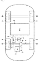
- Fig. 1 schematically illustrates the structure of an electric vehicle in which a battery module according to the embodiment has been installed.
- the vehicle is an electric vehicle driven by only electrical energy.
- the vehicle has an electric motor 2 as a driving source that performs rotational driving using electric power stored in a battery pack 1 having a battery module.
- An inverter 3 is provided between the battery pack 1 and the electric motor 2 to convert DC electric power stored in the battery pack 1 into AC electric power and supplies the AC electric power to the electric motor 2.
- the inverter 3 is controlled by a controller 4 provided in the vehicle.
- the electric motor 2 is ganged and coupled to a pair of left and right drive shafts 7 via a gear train 5 and a differential 6.
- Front wheels 8 are coupled to the outer end portions in the vehicle width direction of the drive shafts 7. That is, this vehicle is a so-called FF vehicle, in which the two left and right front wheels 8 are driving wheels and the two left and right rear wheels 9 are driven wheels.
- the electric motor 2 is driven by electric power supplied by the battery pack 1 when the vehicle is travelling with the accelerator of the vehicle (not illustrated) depressed, and turns the front wheels 8. That is, when the vehicle is powered, the electric motor 2 is driven by the electric power supplied by the battery pack 1 via the inverter 3, and the driving force by the electric motor 2 is transmitted to the front wheels 8 via the gear train 5, the differential 6, and the drive shafts 7.
- each of the front wheel 8 and the rear wheel 9 has a brake device B that applies a braking force by friction.
- the brake system B may be hydraulic or electric.
- the battery pack 1 has a battery stacked body 100 in which a plurality of battery cells 10 are stacked.
- the number of the stacked battery cells 10 is, for example, 36 to 40.
- the battery stacked body 100 is disposed in the vehicle so that the left-right direction (that is, the vehicle width direction) is aligned with the stacking direction of the battery cells 10.
- the length in the stacking direction of the battery stacked body 100 is equal to the length between a pair of left and right side frames.
- the stacking direction is often referred to as the left-right direction simply and the direction orthogonal to the left-right direction and the vertical direction is often referred to as the front-rear direction.
- the left-right direction is equivalent to a first direction
- the front-rear direction is equivalent to a second direction
- the vertical direction is equivalent to a third direction.
- the stacking direction of the battery cells 10 is not limited to the left-right direction.
- the stacking direction of the battery cells 10 may be the front-rear direction.
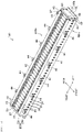
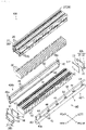
- the battery stacked body 100 has an outer shell portion 80 (see particularly Fig. 3 ) that houses the stacked battery cells 10.
- the outer shell portion 80 includes a pair of end plates 30 disposed so as to sandwich the entire stacked battery cells 10 from both sides in the left-right direction and a pair of side plates 40 disposed so as to sandwich the entire stacked battery cells 10 extending in the left-right direction from both sides in the front-rear direction.
- the battery stacked body 100 has a plurality of frames 20 that fix the battery cells 10 to the outer shell portion 80.
- the end plate 30 on the left side is referred to as a left end plate 30L
- the end plate 30 on the right side is referred to as a right end plate 30R
- the side plate 40 on the front side is referred to as a front side plate 40Fr
- the side plate on the rear side is referred to as a rear side plate 40Rr.
- the left and right end plates 30L and 30R are not distinguished from each other, the left and right end plates 30L and 30R are simply referred to as the end plates 30.
- the front and rear side plates 40Fr and 40Rr are simply referred to as the side plates 40.
- the battery cells 10 are lithium-ion batteries. As illustrated in Fig. 4 , each of the battery cells 10 has a rectangular parallelepiped shape flattened in the left-right direction.
- the battery cell 10 has a pair of first face portions 11 facing each other in the left-right direction, a pair of second face portions 12 facing each other in the front-rear direction, and a pair of third face portions 13 facing each other in the vertical direction.
- the area of the first face portions 11 is much larger than the area of the second face portions 12 and the area of the third face portions 13.
- the first face portions 11, the second face portions 12, and the third face portions 13 are made of, for example, aluminum or aluminum alloy.
- each of the battery cells 10 houses an electrolyte solution and an electrode body 14 immersed in the electrolyte solution in the space formed by the first face portions 11, the second face portions 12, and the third face portions 13.
- the electrode body 14 is formed as a flat circle by spiraling a positive electrode plate 14a and a negative electrode plate 14b and compressing these electrode plates radially. This arranges the positive electrode plates 14a and the negative electrode plates 14b alternately in the left-right direction.
- the upper third face portion 13 of each of the battery cells 10 has a pair of electrode terminals 15.
- the electrode terminals 15 include a positive terminal 15a connected to the positive electrode plate 14a and a negative terminal 15b connected to the negative electrode plate 14b.
- the electrode terminals 15 project upward from the upper third face portion 13.
- the electrode terminals 15 of the adjacent battery cells 10 are connected in series to each other by a busbar. One end portion of the busbar is joined to the positive terminal 15a of the battery cell 10 and the other end portion of the busbar is joined to the negative terminal 15b of the adjacent battery cell 10.
- the frames 20 house the battery cells 10 individually.
- the frames 20 are made of a resin material such as polypropylene, polycarbonate, or polybutylene terephthalate.
- Each of the frames 20 has a pair of front and rear frame bodies 21 that fix the battery cell 10.
- the pair of frame bodies 21 are U-shaped and disposed with the U-shaped openings facing each other.
- the frame bodies 21 cover the entire second face portions 12 of the battery cell 10 and the end portions in the front-rear direction of the third face portions 13 with the two adjacent frames 20 coupled to each other.
- the distance between the middle portions in the vertical direction of the pair of frame bodies 21 is substantially the same as the length (the length in the front-rear direction) of the long sides of the first face portions 11 of the battery cell 10.
- the distance between the upper end portion and the lower end portion of each of the frame bodies 21 is substantially the same as the length (the length in the vertical direction) of the short sides of the first face portions 11 of the battery cell 10.
- first partition walls 22 for partitioning the adjacent battery cells 10 in the left-right direction are provided on the inner side of the frame bodies 21.
- Each of the first partition walls 22 is located in the middle in the width direction of the frame body 21 and extends in the vertical direction.
- the lower end portions of the first partition walls 22 are coupled to each other and the upper end portions of the first partition walls 22 are coupled to each other by second partition walls 23 that extend in the front-rear direction and partition the adjacent battery cells 10 from each other in the left-right direction. That is, the pair frame bodies 21 are coupled to each other by the second partition walls 23.
- the first and second partition walls 22 and 23 are disposed so as to cover the outer circumference portions of the first face portions 11 (see particularly Fig. 4 ).
- the first and second partition walls 22 and 23 have the same thickness, which is approximately 2 to 3 mm.
- Each of the frame bodies 21 has, in the upper end portion and the lower end portion, coupling portions 25 for coupling to an adjacent frame 20.
- the coupling portion 25 has a male-female structure.
- the male portions are formed on the left side and the female portions (not illustrated) are formed on the left side. The male portions are inserted into the female portions of the adjacent frame 20, thereby joining the adjacent frames 20 to each other, as illustrated in Fig. 3 .
- the distance between the second partition walls 23 adjacent to each other in the left-right direction is substantially the same as the width in the left-right direction of the battery cell 10. Accordingly, the battery cell 10 sandwiched between the two frames 20 cannot easily move in the left-right direction. That is, the battery cell 10 is fixed to the outer shell portion by the second partition walls 23.
- the second partition walls 23 are disposed adjacent in the vertical direction to the elastic member 60, which will be described later.
- each of the frame bodies 21 is provided with claw portions 26.
- the claw portions 26 fix the frame 20 to the side plate 40.
- the claw portions 26 are inserted into the engagement holes 45 provided in the side plate 40 and caught by a main surface portion 41 of the side plate 40.
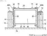
- the frames 20 are located between the side plates 40 and the battery cells 10 and are fixed to the pair of side plates 40, as illustrated in Fig. 5 .
- the method of fixing the frames 20 to the side plates 40 is not limited to the method using the claw portions 26 as described above.
- the frames 20 may be fixed to the side plates 40 by bolts or adhesion.
- end frames 27 are used for the battery cells 10 located at both ends in the left-right direction.
- the end frame 27 has the same basic structure as the normal frame 20 except that the frame body 21 is interrupted in the first and second partition walls 22 and 23.
- Fig. 6 illustrates the end frame 27 on the right side.
- the end frame 27 on the left side is symmetrical with respect to the end frame 27 on the right side.
- the end plate 30 is formed by bending a metal plate made of, for example, aluminum or aluminum alloy into an L-shape, as illustrated in Figs. 2 and 3 .
- the end plate 30 includes a main surface portion 31 extending in the vertical direction and a bottom surface portion 32 extending in the left-right direction from the lower end portion of the main surface portion 31.
- the bottom surface portion 32 of the left end plate 30L extends from the lower end portion of the main surface portion 31 to the left side and the bottom surface portion 32 of the right end plate 30R extends from the lower end portion of the main surface portion 31 to the right side.
- the main surface portion 31 of each of the end plates 30 has two bolt holes 33 in each of the both end portions in the front-rear direction.
- the bolt holes 33 are formed separately from each other in the vertical direction.
- Each of the side plates 40 has a rectangular main surface portion 41 extending in the front-rear direction.
- Each of the side plates 40 has first flange portions 42 extending from the both end portions in the vertical direction of the main surface portion 41 toward the battery cells 10.
- the first flange portions 42 of the front side plate 40Fr extend from both end portions in the vertical direction of the main surface portion 41 toward the rear
- the first flange portions 42 of the rear side plate 40Rr extend from the both end portions in the vertical direction of the main surface portion 41 toward the front.
- the main surface portion 41 and the first flange portions 42 cover the frame bodies 21 of the frames 20 from outside.
- Each of the side plates 40 has second flange portions 43 that extend from the both end portions in the left-right direction of the main surface portion 41 to the left and the right and then bend and extend toward the battery cells 10.
- the second flange portions 43 of the front side plate 40Fr extend from the both end portions in the left-right direction of the main surface portion 41 to the left and right and then extend toward the rear.
- the second flange portions 43 of the rear side plate 40Rr extend from the both end portions in the left-right direction of the main surface portion 41 to the left and the right and then extend toward the front.
- Each of the second flange portions 43 has two bolt holes 43a.
- the two bolt holes 43a are formed separately from each other in the vertical direction so as to correspond to the bolt holes 33 of the end plate 30.
- the end plate 30 and the side plate 40 are coupled to each other, the end plate 30 is first brought into contact with the second flange portion 43 so that the bolt holes 33 of the end plate 30 communicate with the bolt holes 43a of the second flange portion 43. Then, bolts 101 are tightened into the bolt holes 33 and 43a.
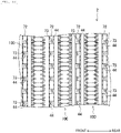
- each of the side plates 40 has a plurality (six in Fig. 7 ) of brackets 44 that extend toward the opposite side of the battery cells 10 in the front-rear direction.
- Each of the brackets 44 is formed by bending an aluminum plate into an L-shape.
- One surface portion of the bracket 44 is welded to the main surface portion 41 of the side plate 40 and the other surface portion of the bracket 44 has a hole.
- the brackets 44 provided in the front side plate 40Fr are staggered with the brackets 44 provided in the rear side plate 40Rr.
- the bracket 44 of the rear side plate 40Rr is disposed in a staggered manner in the portion corresponding to the middle of two adjacent brackets 44 of the front side plate 40Fr.
- the brackets 44 are used to mount the battery stacked body 100 to the cabinet 70 described later.
- a spacer 50 is provided between the end plate 30 on the right side and the end frame 27 on the right side.
- the spacer 50 has approximately the same area as the first surface portion 11 of the battery cell 10.
- step portions 51 onto which the second flange portions 43 of the side plates 40 are fitted are formed in the both end portions in the front-rear direction of the spacer 50.
- the spacer 50 on the left side also has the same structure.
- the inventors of the present application have found that there is a correlation between the constraint force (that is, the force for pressing the battery cells 10 in the stacking direction) in the stacking direction (here, the left-right direction) of the battery cells 10 on the battery cells 10 and the degradation of the battery cells 10.
- Fig. 8 illustrates the relationship between the constraint force in the stacking direction on the battery cells 10 and the internal resistance of the battery cells 10.
- the horizontal axis represents the constraint force in the stacking direction on the battery cells 10 and the vertical axis represents the internal resistance generated in the battery cells 10.
- the solid line represents unused battery cells 10 and the dashed line represents used battery cells 10.
- the relationship between the constraint force in the stacking direction on the battery cells 10 and the internal resistance of the battery cells 10 is like a so-called bathtub curve regardless of whether the battery cells 10 are unused or used to some extent.
- the internal resistance rises in the region in which the constraint force in the stacking direction on the battery cells 10 is excessively large and the region in which the constraint force in the stacking direction on the battery cells 10 is excessively small.
- the constraint force in the stacking direction is excessively large, the electrolyte solution repeatedly sinks into and exudes from the electrode body 14 in the battery cell 10, thereby increasing the uneven concentration of the electrolyte solution. This locally increases the internal resistance.
- the connection portions between the electrode body 14 and the electrode terminals 15 may be overloaded and damaged because the electrode body 14 is easily displaced by vibration of the vehicle.
- the constraint force when the constraint force is excessively large, the internal resistance markedly increases for the battery cell 10 used to some extent.
- a Li-ion battery such as the battery cells 10 continues to be charged, lithium ions are accumulated on the negative electrode plate 14b.
- the electrode body 14 becomes larger by the lithium ions and the battery cells 10 expand in the stacking direction. This further increases the constraint force in the stacking direction and sharply raises the internal resistance as illustrated in Fig. 8 .
- the internal resistance of the battery cells 10 can be maintained at a low level by setting the constraint force in the stacking direction on the battery cells 10 to a value from 1 kN to 10 kN.
- the elastic member 60 is provided between the battery cells 10 that are adjacent to each other in the left-right direction (stacking direction).
- This elastic member 60 is formed by, for example, a foam filler, a gel member, a rubber member, a resin material, or the like.
- the elastic member 60 is disposed so as to cover the central portion of the first surface portion 11 as seen in the left-right direction.
- the elastic member 60 has a size that covers the entire electrode body 14 as seen in the left-right direction.
- the elastic member 60 when the elastic member 60 is sandwiched between the battery cells 10, the elastic member 60 has a rectangular shape as seen in the left-right direction and has a long side that is larger than or equal to the length in the direction (front-rear direction) of the winding axis of the electrode body 14 and a short side that is larger than or equal to the length in the vertical direction of the electrode body 14.
- the elastic member 60 is located at the same position in the left-right direction as the first and second partition walls 22 and 23.
- the elastic member 60 is disposed in the region surrounded by the first and the second partition walls 22 and 23.
- the elastic member 60 has a thickness larger than that of the first and second partition walls 22 and 23 in an unloaded state.
- the elastic member 60 has the same thickness as that of the first and second partition walls 22 and 23 when sandwiched and pressed by the battery cells 10 from both sides in the left-right direction.
- the elastic member 60 presses the battery cells 10 located on the left and right sides with a repulsive force caused when pressed by the battery cells 10 on both sides in the left-right direction.
- the pressing force with which the elastic member 60 presses the adjacent battery cells 10 at this time is set to a value from 1 kN to 10 kN. This can set the constraint force in the stacking direction on the battery cell 10 to a value from 1 kN to 10 kN.
- Each of the elastic members 60 disposed at the left and right ends of the battery stacked body 100 is sandwiched by the spacer 50 and the battery cell 10 in the left-right direction.
- the elastic members 60 need to apply, to the battery cells 10 at the ends, the same repulsive force as when the elastic members 60 are sandwiched between the battery cells 10. This can be done by, for example, causing the spacer 50 to have a hollow box shape similar to the battery cell 10 and the surface portions in the left-right direction to have the same material and thickness as the first surface portions 11 of the battery cell 10.
- the constraint force of the elastic members 60 on the battery cells 10 can be adjusted by changing the material of the elastic members 60 and the thickness of the elastic members 60 relative to the thickness of the first and second partition walls 22 and 23. That is, an increase in the thickness of the elastic member 60 under no load increases a repulsive force of the elastic member 60 when the elastic member 60 is sandwiched between the battery cells 10 so as to have the same thickness as the first and second partition walls 22 and 23. This can adjust the constraint force of the elastic members 60 on the battery cells 10.
- the thickness of the elastic member 60 only needs to be adjusted to a thickness that allows the constraint force in the stacking direction on the battery cells 10 to be set to a value from 1 kN to 10 kN according to Hooke's law depending on the spring constant of the material of the elastic member 60.
- the battery cells 10 expand in the stacking direction.
- the constraint force of the elastic members 60 on the battery cells 10 changes.
- the material and thickness of the elastic members 60 are preferably selected so that the constraint force of the elastic members 60 on the battery cells 10 becomes a value from 1 kN to 10 kN even when the battery cells 10 expand in the stacking direction.
- the internal resistance of the battery cells 10 can be as low as possible by setting the constraint force on the battery cells 10 to an appropriate value. This can extend the service life of the battery cells 10.
- the battery stacked body 100 constructed as described above is mounted to the cabinet 70 made of a resin.
- the cabinet 70 is box-shaped and a plurality (five in Fig. 9 ) of cross members 72 that extend so as to couple side wall portions 71 arranged in the left-right direction are provided in parallel to the front-rear direction.
- the battery pack 1 is mounted to the cabinet 70 with the plurality of battery stacked bodies 100 arranged in the front-rear direction.
- the cabinet 70 has a lid member that covers the battery stacked bodies 100 from above with the battery stacked bodies 100 mounted to the cabinet 70.
- the brackets 44 of the side plates 40 are placed on the cross members 72 from above.
- the battery stacked bodies 100 are supported by the cross members 72 by passing bolts 73 through the holes of the brackets 44 and tightening the bolts 73 to the cross members 72. That is, the cross members 72 correspond to the support portions that are coupled to the brackets 44 of the side plates 40 and support the battery stacked bodies 100.
- brackets 44 provided in the front side plate 40Fr are staggered with the brackets 44 provided in the rear side plate 40Fr as illustrated in Fig. 10 , a bracket 44 of one battery stacked body 100 can be disposed between brackets 44 of an adjacent battery stacked body 100. Accordingly, the width of the cross member 72 can be as small as possible and the cabinet 70 can be compact. As a result, the entire battery pack 1 can be compact. In addition, the distance between the mounting portions of the battery stacked body 100 with respect to the cross members 72 is reduced. Since the resonance frequency of the battery stacked body 100 becomes high when the distance between the mounting portions is reduced, the vibration of the battery stacked body 100 can be easily suppressed.
- the battery stacked body 100 when the battery stacked body 100 is supported by the cross members 72, the battery stacked body 100 is separated from a bottom wall portion 74 of the cabinet 70. This can make the contact points between the cabinet 70 and the battery stacked body 100 as few as possible. As a result, the transmission of vibration of the vehicle to the battery cells 10 can be suppressed as much as possible.
- the battery pack 1 includes the plurality of battery cells 10 stacked in the left-right direction, each of the battery cells 10 including the pair of first surface portions 11 facing each other in the left-right direction (stacking direction), the pair of second surface portions 12 facing each other in the front-rear direction, the pair of third surface portions 13 facing each other in the vertical direction, and the electrode body 14 in which the positive electrode plate 14a and the negative electrode plate 14b are arranged in the left-right direction in the space formed by the first surface portions 11, the second surface portions 12, and the third surface portions 13; the outer shell portion 80 that houses the stacked battery cells 10; the elastic members 60, each of which is provided between the battery cells 10 adjacent to each other in the left-right direction (stacking direction); and the plurality of frames 20 that fix the battery cells 10 to the outer shell portion 80, in which the elastic members 60 are disposed so as to cover the central portions of the first surface portions 11.
- the central portions of the first surface portions 11 of the battery cells 10 are likely to expand and this expansion increases the constraint force in the stacking direction on the battery cells 10.
- the elastic members 60 deform so as to shrink according to the expansion of the central portions of the first surface portions 11. This can suppress an increase in loads on the battery cells 10 due to the expansion as compared with the case in which, for example, the central portions of the first surface portions 11 of the battery cells 10 are covered with non-elastic members. As a result, the battery cells 10 remain constrained with a low load.
- the battery cells 10 are supported by the outer shell portion 80 via the frames 20, the displacement of the battery cells 10 due to vibration is also suppressed.
- the displacement in the left-right direction (stacking direction) of the battery cells 10 can be effectively suppressed by disposing the first and second partition walls 22 and 23 of the frames 20 in the outer circumference portions of the first surface portions 11 of each of the battery cells 10, which is less likely to expand.
- uneven concentration of the electrolyte solution and uneven distance between the electrode plates 14a and 14b are suppressed while the battery cells 10 are fixed. Accordingly, an increase in the internal resistances of the battery cells 10 are suppressed, thereby extending the service life of the battery cells 10.
- first and second partition walls 22 and 23 are disposed in the outer circumference portions of the first surface portions 11 of each of the battery cells 10, which is less likely to expand, the first and second partition walls 22 and 23 are also prevented from being damaged by the expansion of the battery cells 10.
- the battery module can be compact.
- the length in the left-right direction of the battery pack 1 does not change. Accordingly, a displacement-absorbing mechanism, which is generally disposed in the fixed portion of the battery pack 1, does not need to be installed, so the battery pack 1 can be compact.
- the elastic members 60 have a size that covers the entire electrode body 14 as seen in the left-right direction. This can appropriately constrain the portions of the battery cells 10 in which the electrode bodies 14 are provided. As a result, a rise of the internal resistance of the battery cells 10 can be more effectively suppressed and the service life of the battery cells 10 can be further extended.
- the frames 20 are formed so as to cover the outer circumference portions of the battery cells 10 and the battery cells 10 are fixed to the outer shell portion 80 by fixing the frames 20 to the outer shell portion 80 with the battery cells 10 put in the frames 20. Accordingly, the entire battery cells 10 can be supported by the frames 20. As a result, the battery cells 10 can be prevented from being moved and broken due to vibration of the vehicle or the like. In addition, since the outer circumference portions of the battery cells 10 are less likely to expand, the internal resistance does not easily rise even when a rigid body is disposed. Accordingly, the service life of the battery cells 10 can be further extended.
- the outer shell portion 80 includes the pair of end plates 30 disposed so as to sandwich the entire stacked battery cells 10 from both sides in the left-right direction and the pair of side plates 40, extending in the left-right direction, that is disposed so as to sandwich the entire stacked battery cells 10 from both sides in the front-rear direction, and the frames 20 are located between the side plates 40 and the battery cells 10 and are fixed to the pair of side plates 40. Since the frames 20 are fixed to the side plates 40, the frames 20 does not easily move in the left-right direction and does not generate a constraint force in the left-right direction on the battery cells 10. Since the frames 20 do not apply a constraint force to the battery cells 10, the constraint force on the battery cells 10 are given by the elastic members 60. Accordingly, the constraint force in the left-right direction on the battery cells 10 can be easily set to an appropriate value and the service life of the battery cells 10 can be easily extended.
- each of the side plates 40 has the second flange portions 43 that are provided in both end portions in the left-right direction, extend in the left-right direction, and are bent toward the battery cells 10 in the front-rear direction, and the end plates 30 are coupled to the second flange portions 43 via bolts. Since the connection portions between the end plates 30 and the side plates 40 are separated from the battery cells 10, the connections between the end plates 30 and the side plates 40 hardly affect the constraint force in the left-right direction on the battery cells 10. Accordingly, the constraint force in the left-right direction on the battery cells 10 can be easily set to an appropriate value and the service life of the battery cells 10 can be easily extended.
- the elastic member 60 has a size that covers the entire electrode body 14 as seen in the stacking direction (left-right direction).
- the technology is not limited to the embodiment and the size of the elastic member 60 may be slightly smaller than that of the electrode body 14 as seen in the stacking direction.
- the length in the stacking direction of the battery stacked body 100 is equal to the length between the pair of side frames.
- the technology is not limited to this embodiment and the length in the stacking direction of the battery stacked body 100 may be smaller than the length between the pair of side frames.
- the technology disclosed herein is useful for a battery module including a plurality of battery cells stacked in a first direction, each of the battery cells including a pair of first surface portions facing each other in the first direction, a pair of second surface portions facing each other in a second direction orthogonal to the first direction, a pair of third surface portions facing each other in a third direction orthogonal to the first direction and the second direction, and an electrode body in which a positive electrode plate and a negative electrode plate are disposed in the first direction in a space formed by the first surface portions, the second surface portions, and the third surface portions.
Landscapes
- Chemical & Material Sciences (AREA)
- Chemical Kinetics & Catalysis (AREA)
- Electrochemistry (AREA)
- General Chemical & Material Sciences (AREA)
- Engineering & Computer Science (AREA)
- Aviation & Aerospace Engineering (AREA)
- Battery Mounting, Suspending (AREA)
Abstract
Description
- The technology disclosed herein belongs to a technical field regarding a battery module.
- In recent years, vehicles that move using a motor torque generated by a motor, such as electric vehicles and hybrid vehicles have become popular. Such a vehicle has a battery module that stores electric power to be supplied to a motor. Many of battery modules provided in vehicles are formed by stacking a plurality of rectangular parallelepiped battery cells.
- For example, the battery module described in
patent document 1 includes a cell stacked body in which a plurality of battery cells are stacked in a first direction with insulators sandwiched therebetween, a pair of end plates disposed on both side surfaces in the first direction of the cell stacked body, and a pair of side frames disposed on both side surfaces in the second direction orthogonal to the first direction of the cell stacked body, in which each of the side frames has a front flange portion that extends along the front end plate so as to close to each other and a rear flange portion that extends along the rear end plate so as to close to each other, the front flange portion is fastened to the front end plate and the rear flange portion is fastened to the rear end plate, and the battery cells are allowed to expand in the first direction due to degradation according to changes in the angles of the front flange portion and the rear flange portion. - In addition, the battery module described in
patent document 2 includes battery cells, a case that houses the battery cells, a foamed coating layer sandwiched between the outer surface of the battery cells and the inner surface of the case, in which partition plates extending from the case are disposed at the positions corresponding to the outer circumference portions of the surface portions in the stacking direction of the battery cells and clearances are present in the portions corresponding to the centers of the surface portions of the battery cells. -
- Patent Literature 1:
JP-A-2019-75281 - Patent Literature 2:
JP-A-2013-191440 - By the way, as a result of diligent study, the inventors of the present application have found that there is a correlation between the constraint force applied to the battery cells in the stacking direction and degradation of the battery cells.
- Specifically, in the structure that absorbs the expansion of the battery cells using the warp of the flanges provided in the side flames as in the battery module described in
patent document 1, the spring force of the flange becomes strong particularly when the battery cells expand, and the constraint force in the stacking direction becomes high. When the constraint force in the stacking direction is strong, the electrolyte solution repeatedly sinks into and exudes from the electrodes, thereby increasing the uneven concentration of the electrolyte solution. This locally increases the internal resistance and degrades the battery cells. - In contrast, the constraint force in the stacking direction is substantially zero in the central portions of the battery cells when there is a clearance between battery cells as in the battery module described in
patent document 2. When the constraint force in the stacking direction is too weak, the distance between electrodes becomes uneven. This locally increases the internal resistance. In addition, in the case of an in-vehicle battery module, since vibration of a vehicle easily displaces the electrodes, connection portions between the electrode body and the terminals are loaded and damaged, thereby reducing the service life of the battery cell. - The technology disclosed herein easily extends the service life of the battery cells by setting the constraint force in the stacking direction on the battery cells to an appropriate value in a battery module in which a plurality of battery cells are stacked.
- The inventors of the present application have disposed soft members in a portion in the battery cells that are likely to expand and constrained the battery cells with a low load.
- Specifically, the technology disclosed herein has a structure including battery cells, each of the battery cells including a pair of first surface portions facing each other in the first direction, a pair of second surface portions facing each other in a second direction orthogonal to the first direction, a pair of third surface portions facing each other in a third direction orthogonal to the first direction and the second direction, and an electrode body in which a positive electrode plate and a negative electrode plate are arranged in the first direction in a space formed by the first surface portions, the second surface portions, and the third surface portions; an outer shell portion that houses the stacked battery cells; elastic members, each of which is provided between the battery cells adjacent to each other in the first direction; and fixed portions that fix the battery cells to the outer shell portion, in which the elastic members are disposed so as to cover central portions of the first surface portions, and the fixed portions are disposed so as to cover outer circumference portions of the first surface portions.
- That is, the central portions of the first surface portions of the battery cells are likely to expand and this expansion makes the constraint force in the stacking direction on the battery cells high. In contrast, in the structure described above, the elastic members are disposed between the adjacent battery cells in the first direction, so the elastic members deform so as to shrink according to the expansion of the central portions of the first surface portions. This can suppress an increase in loads on the battery cells due to the expansion as compared with the case in which, for example, the central portions of the first surface portions of the battery cells are covered with non-elastic members. As a result, the battery cells remain constrained with a low load. By disposing the fixed portions in the outer circumference portions of the battery cells, which are less likely to expand, it is possible to suppress an increase in displacement of the battery cells due to vibration and the fixed portions can also prevent an increase in the constraint force in the stacking direction on the battery cells. Since this prevents uneven distance between the electrodes and uneven concentration of the electrolyte solution while fixing the battery cells, an increase in the internal resistance of the battery cells is suppressed, thereby extending the service life of the battery cells.
- In the battery module, the elastic members may have a size that covers the entire electrode body as seen in the first direction.
- In this structure, the elastic members has a size that covers the entire electrode body, so the elastic members can appropriately constrain the portion in which the electrode body is provided. Since a load is applied to the entire electrode body evenly, a rise of the internal resistance of the battery cell can be more effectively suppressed and the service life of the battery cells can be further extended.
- In the battery module, the fixed portions may include resin frames formed so as to cover outer circumference portions of the battery cells, and the battery cells may be fixed to the outer shell portion by fixing the frames to the outer shell portion with the battery cells put in the frames.
- In this structure, since the fixed portions include the frames that cover the outer circumference portions of the battery cells, the frames can support the entire battery cell. In addition, since the outer circumference portions of the battery cells are less likely to expand, the internal resistance does not easily rise even when a rigid body is disposed. Accordingly, the service life of the battery cells can be further extended.
- In an embodiment of the battery module, the outer shell portion includes a pair of end plates disposed so as to sandwich the entire stacked battery cells from both sides in the first direction and a pair of side plates disposed so as to sandwich the entire stacked battery cells from both sides in the second direction, the side plates extending in the first direction, and the fixed portions are located between the side plates and the battery cells and are fixed to the pair of side plates.
- In this structure, since the fixed portions are fixed to the side plates, the fixed portions do not easily move in the first direction and do not cause the battery cells to generate a constraint force in the first direction. Since the fixed portions do not apply a constraint force to the battery cells, the constraint force on the battery cells are given by the elastic member. This easily sets the constraint force in the first direction on the battery cells to an appropriate value, thereby easily extending the service life of the battery cells.
- In the embodiment, each of the side plates may have flange portions provided in both end portions in the first direction, the side plates extending in the first direction and then being bent toward the battery cells in the second direction, and the end plates may be coupled to the flange portion via a bolt.
- Since the connection portions between the end plates and the side plates are separated from the battery cells in this structure, the connections between the end plates and the side plates hardly affect the constraint force in the first direction on the battery cells. This easily sets the constraint force in the first direction on the battery cells to an appropriate value, thereby easily extending the service life of the battery cells.
- In the embodiment, the battery module may further include a cabinet to which a battery stacked body having the plurality of battery cells housed in the outer shell portion is mounted, in which each of the side plate may have a bracket that extends toward an opposite side of the battery cells in the second direction, the bracket being fixed to the cabinet, and the cabinet may have a support portion coupled to the bracket, the support portion supporting the battery stacked body.
- In this structure, the side plates are less likely to deform in the first direction. This causes the side plates not to easily generate a constraint force in the first direction on the battery cells. As a result, the constraint force in the first direction on the battery cells is kept at an appropriate value, thereby further extending the service life of the battery cells.
- In the embodiment in which the battery stacked body is mounted to the cabinet, a plurality of battery stacked bodies may be mounted to the cabinet with the battery stacked bodies arranged in the second direction, the battery stacked body being one of the plurality of battery stacked bodies, a plurality of brackets may be present and may be mounted to the support portion with the brackets placed on the support portion in a third direction, the bracket being one of the plurality of brackets, and the brackets provided on one side of the side plate in the second direction may be staggered with the brackets provided on the other side of the side plate in the second direction.
- In this structure, the brackets of adjacent battery stacked bodies can be alternately arranged in the support portions. This reduces the distance between the mounting portions with respect to the support portions. Since the resonance frequency of the battery module increases when the distance between the mounting portions is reduced, the vibration of the battery module can be easily suppressed. In addition, since adjacent battery stacked bodies can be disposed as close as possible to each other, the entire battery module can be compact.
- In the embodiment in which the battery stacked body is mounted to the cabinet, portions of the battery stacked bodies excluding the brackets may be separated from the cabinet with the battery stacked bodies supported by the support portion.
- In this structure, transmission of vibration applied to the cabinet to the battery stacked body can be suppressed. This can suppress the displacement of the electrodes due to vibration, thereby further extending the service life of the battery cells.
- In the battery module, a force used by each of the elastic members to press an adjacent one of the battery cells is preferably set to 1 kN to 10 kN.
- As a result of study, the inventors of the present application have found that when the constraint force in the first direction on the battery cells is set to approximately 1 kN to 10 kN, even if the battery cells expand due to aged degradation, the internal resistance is nearly unchanged, which depends on the internal electrode specifications and the size of the battery cells. Accordingly, the structure described above can further extend the service life of the battery cells.
- In the battery module, a length in the first direction of the battery stacked body having the plurality of battery cells housed in the outer shell portion may be equal to a length between a pair of side flames.
- That is, since the battery cells only need to be constrained with a low constraint force in the first direction, the constraint force can be easily uniformed and the number of stacked battery cells can be as large as possible. Then, the battery capacity can be considerably increased by making the length in the first direction of the battery stacked body nearly equal to the length between the side frames. Accordingly, the battery capacity can be increased while the service life thereof can be extended.
- As described above, the technology disclosed herein can extend the service life of the battery cells by setting the constraint force in the stacking direction on the battery cells to an appropriate value.
-
- [
Fig. 1] Fig. 1 is a schematic diagram illustrating the structure of a vehicle in which a battery pack according to an exemplary embodiment is disposed. - [
Fig. 2] Fig. 2 is a perspective view of a battery stacked body. - [
Fig. 3] Fig. 3 is an exploded perspective view of the battery stacked body. - [
Fig. 4] Fig. 4 is an exploded perspective view illustrating the structure of one of battery cells. - [
Fig. 5] Fig. 5 is a front view of the battery cell as seen in the stacking direction. - [
Fig. 6] Fig. 6 is a sectional view of the right end portion in the stacking direction of the battery stacked body, taken along a plane parallel to the stacking direction and the vertical direction. - [
Fig. 7] Fig. 7 is a plan view of the battery stacked body as seen from above. - [
Fig. 8] Fig. 8 is a graph illustrating the relationship between the constraint force in the stacking direction and the internal resistance of the battery stacked body. - [
Fig. 9] Fig. 9 is a perspective view illustrating the relationship between the battery stacked body and a cabinet. - [
Fig. 10] Fig. 10 is an enlarged plan view, as seen from above, illustrating a mounting portion of the battery stacked body to the cabinet. - [
Fig. 11] Fig. 11 illustrates a sectional view illustrating the mounting portion of the battery stacked body to the cabinet. - An exemplary embodiment will be described in detail below with reference to the drawings.
-
Fig. 1 schematically illustrates the structure of an electric vehicle in which a battery module according to the embodiment has been installed. The vehicle is an electric vehicle driven by only electrical energy. The vehicle has anelectric motor 2 as a driving source that performs rotational driving using electric power stored in abattery pack 1 having a battery module. Aninverter 3 is provided between thebattery pack 1 and theelectric motor 2 to convert DC electric power stored in thebattery pack 1 into AC electric power and supplies the AC electric power to theelectric motor 2. Theinverter 3 is controlled by acontroller 4 provided in the vehicle. - The
electric motor 2 is ganged and coupled to a pair of left andright drive shafts 7 via a gear train 5 and a differential 6.Front wheels 8 are coupled to the outer end portions in the vehicle width direction of thedrive shafts 7. That is, this vehicle is a so-called FF vehicle, in which the two left and rightfront wheels 8 are driving wheels and the two left and rightrear wheels 9 are driven wheels. - The
electric motor 2 is driven by electric power supplied by thebattery pack 1 when the vehicle is travelling with the accelerator of the vehicle (not illustrated) depressed, and turns thefront wheels 8. That is, when the vehicle is powered, theelectric motor 2 is driven by the electric power supplied by thebattery pack 1 via theinverter 3, and the driving force by theelectric motor 2 is transmitted to thefront wheels 8 via the gear train 5, the differential 6, and thedrive shafts 7. - In the vehicle, each of the
front wheel 8 and therear wheel 9 has a brake device B that applies a braking force by friction. The brake system B may be hydraulic or electric. - As illustrated in
Figs. 2 and3 , thebattery pack 1 has a battery stackedbody 100 in which a plurality ofbattery cells 10 are stacked. The number of the stackedbattery cells 10 is, for example, 36 to 40. In the embodiment, the battery stackedbody 100 is disposed in the vehicle so that the left-right direction (that is, the vehicle width direction) is aligned with the stacking direction of thebattery cells 10. The length in the stacking direction of the battery stackedbody 100 is equal to the length between a pair of left and right side frames. In the following description, the stacking direction is often referred to as the left-right direction simply and the direction orthogonal to the left-right direction and the vertical direction is often referred to as the front-rear direction. In this case, the left-right direction is equivalent to a first direction, the front-rear direction is equivalent to a second direction, and the vertical direction is equivalent to a third direction. It should be noted that the stacking direction of thebattery cells 10 is not limited to the left-right direction. The stacking direction of thebattery cells 10 may be the front-rear direction. - The battery stacked
body 100 has an outer shell portion 80 (see particularlyFig. 3 ) that houses the stackedbattery cells 10. Theouter shell portion 80 includes a pair of end plates 30 disposed so as to sandwich the entirestacked battery cells 10 from both sides in the left-right direction and a pair of side plates 40 disposed so as to sandwich the entirestacked battery cells 10 extending in the left-right direction from both sides in the front-rear direction. The battery stackedbody 100 has a plurality offrames 20 that fix thebattery cells 10 to theouter shell portion 80. In the following description, the end plate 30 on the left side is referred to as aleft end plate 30L, the end plate 30 on the right side is referred to as aright end plate 30R, the side plate 40 on the front side is referred to as a front side plate 40Fr, and the side plate on the rear side is referred to as a rear side plate 40Rr. When the left andright end plates right end plates - The
battery cells 10 are lithium-ion batteries. As illustrated inFig. 4 , each of thebattery cells 10 has a rectangular parallelepiped shape flattened in the left-right direction. Thebattery cell 10 has a pair offirst face portions 11 facing each other in the left-right direction, a pair ofsecond face portions 12 facing each other in the front-rear direction, and a pair ofthird face portions 13 facing each other in the vertical direction. The area of thefirst face portions 11 is much larger than the area of thesecond face portions 12 and the area of thethird face portions 13. Thefirst face portions 11, thesecond face portions 12, and thethird face portions 13 are made of, for example, aluminum or aluminum alloy. - As illustrated in
Fig. 6 , each of thebattery cells 10 houses an electrolyte solution and anelectrode body 14 immersed in the electrolyte solution in the space formed by thefirst face portions 11, thesecond face portions 12, and thethird face portions 13. Theelectrode body 14 is formed as a flat circle by spiraling apositive electrode plate 14a and anegative electrode plate 14b and compressing these electrode plates radially. This arranges thepositive electrode plates 14a and thenegative electrode plates 14b alternately in the left-right direction. - The upper
third face portion 13 of each of thebattery cells 10 has a pair ofelectrode terminals 15. Theelectrode terminals 15 include apositive terminal 15a connected to thepositive electrode plate 14a and anegative terminal 15b connected to thenegative electrode plate 14b. Theelectrode terminals 15 project upward from the upperthird face portion 13. Although not illustrated in the diagram, theelectrode terminals 15 of theadjacent battery cells 10 are connected in series to each other by a busbar. One end portion of the busbar is joined to thepositive terminal 15a of thebattery cell 10 and the other end portion of the busbar is joined to thenegative terminal 15b of theadjacent battery cell 10. - As illustrated in
Figs. 3 and4 , theframes 20 house thebattery cells 10 individually. Theframes 20 are made of a resin material such as polypropylene, polycarbonate, or polybutylene terephthalate. Each of theframes 20 has a pair of front andrear frame bodies 21 that fix thebattery cell 10. The pair offrame bodies 21 are U-shaped and disposed with the U-shaped openings facing each other. As illustrated inFigs. 2 and5 , theframe bodies 21 cover the entiresecond face portions 12 of thebattery cell 10 and the end portions in the front-rear direction of thethird face portions 13 with the twoadjacent frames 20 coupled to each other. The distance between the middle portions in the vertical direction of the pair offrame bodies 21 is substantially the same as the length (the length in the front-rear direction) of the long sides of thefirst face portions 11 of thebattery cell 10. In addition, the distance between the upper end portion and the lower end portion of each of theframe bodies 21 is substantially the same as the length (the length in the vertical direction) of the short sides of thefirst face portions 11 of thebattery cell 10. - As illustrated in
Figs. 4 and5 ,first partition walls 22 for partitioning theadjacent battery cells 10 in the left-right direction are provided on the inner side of theframe bodies 21. Each of thefirst partition walls 22 is located in the middle in the width direction of theframe body 21 and extends in the vertical direction. The lower end portions of thefirst partition walls 22 are coupled to each other and the upper end portions of thefirst partition walls 22 are coupled to each other bysecond partition walls 23 that extend in the front-rear direction and partition theadjacent battery cells 10 from each other in the left-right direction. That is, thepair frame bodies 21 are coupled to each other by thesecond partition walls 23. The first andsecond partition walls Fig. 4 ). The first andsecond partition walls - Each of the
frame bodies 21 has, in the upper end portion and the lower end portion,coupling portions 25 for coupling to anadjacent frame 20. Thecoupling portion 25 has a male-female structure. In the example illustrated inFig. 4 , the male portions are formed on the left side and the female portions (not illustrated) are formed on the left side. The male portions are inserted into the female portions of theadjacent frame 20, thereby joining theadjacent frames 20 to each other, as illustrated inFig. 3 . - As illustrated in
Fig. 6 , when theadjacent frames 20 are coupled to each other, the distance between thesecond partition walls 23 adjacent to each other in the left-right direction is substantially the same as the width in the left-right direction of thebattery cell 10. Accordingly, thebattery cell 10 sandwiched between the twoframes 20 cannot easily move in the left-right direction. That is, thebattery cell 10 is fixed to the outer shell portion by thesecond partition walls 23. Thesecond partition walls 23 are disposed adjacent in the vertical direction to theelastic member 60, which will be described later. - The outer surface of each of the
frame bodies 21 is provided withclaw portions 26. Theclaw portions 26 fix theframe 20 to the side plate 40. Theclaw portions 26 are inserted into the engagement holes 45 provided in the side plate 40 and caught by amain surface portion 41 of the side plate 40. Accordingly, theframes 20 are located between the side plates 40 and thebattery cells 10 and are fixed to the pair of side plates 40, as illustrated inFig. 5 . It should be noted that that the method of fixing theframes 20 to the side plates 40 is not limited to the method using theclaw portions 26 as described above. Theframes 20 may be fixed to the side plates 40 by bolts or adhesion. - As illustrated in
Fig. 6 , end frames 27 are used for thebattery cells 10 located at both ends in the left-right direction. Theend frame 27 has the same basic structure as thenormal frame 20 except that theframe body 21 is interrupted in the first andsecond partition walls Fig. 6 illustrates theend frame 27 on the right side. Theend frame 27 on the left side is symmetrical with respect to theend frame 27 on the right side. - The end plate 30 is formed by bending a metal plate made of, for example, aluminum or aluminum alloy into an L-shape, as illustrated in
Figs. 2 and3 . Specifically, the end plate 30 includes amain surface portion 31 extending in the vertical direction and abottom surface portion 32 extending in the left-right direction from the lower end portion of themain surface portion 31. Thebottom surface portion 32 of theleft end plate 30L extends from the lower end portion of themain surface portion 31 to the left side and thebottom surface portion 32 of theright end plate 30R extends from the lower end portion of themain surface portion 31 to the right side. As illustrated inFig. 3 , themain surface portion 31 of each of the end plates 30 has twobolt holes 33 in each of the both end portions in the front-rear direction. The bolt holes 33 are formed separately from each other in the vertical direction. - Each of the side plates 40 has a rectangular
main surface portion 41 extending in the front-rear direction. Each of the side plates 40 hasfirst flange portions 42 extending from the both end portions in the vertical direction of themain surface portion 41 toward thebattery cells 10. Specifically, thefirst flange portions 42 of the front side plate 40Fr extend from both end portions in the vertical direction of themain surface portion 41 toward the rear, and thefirst flange portions 42 of the rear side plate 40Rr extend from the both end portions in the vertical direction of themain surface portion 41 toward the front. As illustrated inFig. 5 , themain surface portion 41 and thefirst flange portions 42 cover theframe bodies 21 of theframes 20 from outside. - Each of the side plates 40 has
second flange portions 43 that extend from the both end portions in the left-right direction of themain surface portion 41 to the left and the right and then bend and extend toward thebattery cells 10. Specifically, thesecond flange portions 43 of the front side plate 40Fr extend from the both end portions in the left-right direction of themain surface portion 41 to the left and right and then extend toward the rear. On the other hand, thesecond flange portions 43 of the rear side plate 40Rr extend from the both end portions in the left-right direction of themain surface portion 41 to the left and the right and then extend toward the front. Each of thesecond flange portions 43 has twobolt holes 43a. The twobolt holes 43a are formed separately from each other in the vertical direction so as to correspond to the bolt holes 33 of the end plate 30. When the end plate 30 and the side plate 40 are coupled to each other, the end plate 30 is first brought into contact with thesecond flange portion 43 so that the bolt holes 33 of the end plate 30 communicate with the bolt holes 43a of thesecond flange portion 43. Then,bolts 101 are tightened into the bolt holes 33 and 43a. - As illustrated in
Figs. 5 and7 , each of the side plates 40 has a plurality (six inFig. 7 ) ofbrackets 44 that extend toward the opposite side of thebattery cells 10 in the front-rear direction. Each of thebrackets 44 is formed by bending an aluminum plate into an L-shape. One surface portion of thebracket 44 is welded to themain surface portion 41 of the side plate 40 and the other surface portion of thebracket 44 has a hole. Thebrackets 44 provided in the front side plate 40Fr are staggered with thebrackets 44 provided in the rear side plate 40Rr. Specifically, thebracket 44 of the rear side plate 40Rr is disposed in a staggered manner in the portion corresponding to the middle of twoadjacent brackets 44 of the front side plate 40Fr. Although described in more detail later, thebrackets 44 are used to mount the battery stackedbody 100 to thecabinet 70 described later. - As illustrated in
Fig. 6 , aspacer 50 is provided between the end plate 30 on the right side and theend frame 27 on the right side. Thespacer 50 has approximately the same area as thefirst surface portion 11 of thebattery cell 10. As illustrated inFig. 7 ,step portions 51 onto which thesecond flange portions 43 of the side plates 40 are fitted are formed in the both end portions in the front-rear direction of thespacer 50. Thespacer 50 on the left side also has the same structure. - As a result of diligent study, the inventors of the present application have found that there is a correlation between the constraint force (that is, the force for pressing the
battery cells 10 in the stacking direction) in the stacking direction (here, the left-right direction) of thebattery cells 10 on thebattery cells 10 and the degradation of thebattery cells 10. -
Fig. 8 illustrates the relationship between the constraint force in the stacking direction on thebattery cells 10 and the internal resistance of thebattery cells 10. The horizontal axis represents the constraint force in the stacking direction on thebattery cells 10 and the vertical axis represents the internal resistance generated in thebattery cells 10. The solid line representsunused battery cells 10 and the dashed line represents usedbattery cells 10. - It can be seen from
Fig. 8 that the relationship between the constraint force in the stacking direction on thebattery cells 10 and the internal resistance of thebattery cells 10 is like a so-called bathtub curve regardless of whether thebattery cells 10 are unused or used to some extent. Specifically, it can be seen that the internal resistance rises in the region in which the constraint force in the stacking direction on thebattery cells 10 is excessively large and the region in which the constraint force in the stacking direction on thebattery cells 10 is excessively small. When the constraint force in the stacking direction is excessively large, the electrolyte solution repeatedly sinks into and exudes from theelectrode body 14 in thebattery cell 10, thereby increasing the uneven concentration of the electrolyte solution. This locally increases the internal resistance. In contrast, when the constraint force in the stacking direction is too small, the distance between thepositive electrode plate 14a and thenegative electrode plate 14b becomes uneven. This locally increases the internal resistance. When thebattery pack 1 is installed in a vehicle as in the embodiment, the connection portions between theelectrode body 14 and theelectrode terminals 15 may be overloaded and damaged because theelectrode body 14 is easily displaced by vibration of the vehicle. - In particular, when the constraint force is excessively large, the internal resistance markedly increases for the
battery cell 10 used to some extent. When a Li-ion battery such as thebattery cells 10 continues to be charged, lithium ions are accumulated on thenegative electrode plate 14b. Theelectrode body 14 becomes larger by the lithium ions and thebattery cells 10 expand in the stacking direction. This further increases the constraint force in the stacking direction and sharply raises the internal resistance as illustrated inFig. 8 . - In contrast, as illustrated by hatching in
Fig. 8 , when the constraint force in the stacking direction on thebattery cells 10 is set to an appropriate value, the internal resistance can be maintained at a low level even if thebattery cell 10 degrades to some extent. As a result of study, the inventors of the present application have found that the internal resistance of thebattery cells 10 can be maintained at a low level by setting the constraint force in the stacking direction on thebattery cells 10 to a value from 1 kN to 10 kN. - Accordingly, in the embodiment, the
elastic member 60 is provided between thebattery cells 10 that are adjacent to each other in the left-right direction (stacking direction). Thiselastic member 60 is formed by, for example, a foam filler, a gel member, a rubber member, a resin material, or the like. As illustrated inFig. 5 , theelastic member 60 is disposed so as to cover the central portion of thefirst surface portion 11 as seen in the left-right direction. Theelastic member 60 has a size that covers theentire electrode body 14 as seen in the left-right direction. Specifically, when theelastic member 60 is sandwiched between thebattery cells 10, theelastic member 60 has a rectangular shape as seen in the left-right direction and has a long side that is larger than or equal to the length in the direction (front-rear direction) of the winding axis of theelectrode body 14 and a short side that is larger than or equal to the length in the vertical direction of theelectrode body 14. - As illustrated in
Fig. 5 and6 , theelastic member 60 is located at the same position in the left-right direction as the first andsecond partition walls elastic member 60 is disposed in the region surrounded by the first and thesecond partition walls elastic member 60 has a thickness larger than that of the first andsecond partition walls elastic member 60 has the same thickness as that of the first andsecond partition walls battery cells 10 from both sides in the left-right direction. Theelastic member 60 presses thebattery cells 10 located on the left and right sides with a repulsive force caused when pressed by thebattery cells 10 on both sides in the left-right direction. The pressing force with which theelastic member 60 presses theadjacent battery cells 10 at this time is set to a value from 1 kN to 10 kN. This can set the constraint force in the stacking direction on thebattery cell 10 to a value from 1 kN to 10 kN. - Each of the
elastic members 60 disposed at the left and right ends of the battery stackedbody 100 is sandwiched by thespacer 50 and thebattery cell 10 in the left-right direction. At this time, theelastic members 60 need to apply, to thebattery cells 10 at the ends, the same repulsive force as when theelastic members 60 are sandwiched between thebattery cells 10. This can be done by, for example, causing thespacer 50 to have a hollow box shape similar to thebattery cell 10 and the surface portions in the left-right direction to have the same material and thickness as thefirst surface portions 11 of thebattery cell 10. - The constraint force of the
elastic members 60 on thebattery cells 10 can be adjusted by changing the material of theelastic members 60 and the thickness of theelastic members 60 relative to the thickness of the first andsecond partition walls elastic member 60 under no load increases a repulsive force of theelastic member 60 when theelastic member 60 is sandwiched between thebattery cells 10 so as to have the same thickness as the first andsecond partition walls elastic members 60 on thebattery cells 10. The thickness of theelastic member 60 only needs to be adjusted to a thickness that allows the constraint force in the stacking direction on thebattery cells 10 to be set to a value from 1 kN to 10 kN according to Hooke's law depending on the spring constant of the material of theelastic member 60. - As described above, when the
battery pack 1 continues to be charged, thebattery cells 10 expand in the stacking direction. When thebattery cells 10 expand in the stacking direction, the constraint force of theelastic members 60 on thebattery cells 10 changes. Accordingly, the material and thickness of theelastic members 60 are preferably selected so that the constraint force of theelastic members 60 on thebattery cells 10 becomes a value from 1 kN to 10 kN even when thebattery cells 10 expand in the stacking direction. - As described above, the internal resistance of the
battery cells 10 can be as low as possible by setting the constraint force on thebattery cells 10 to an appropriate value. This can extend the service life of thebattery cells 10. - In the
battery pack 1, the battery stackedbody 100 constructed as described above is mounted to thecabinet 70 made of a resin. As illustrated inFig. 9 , thecabinet 70 is box-shaped and a plurality (five inFig. 9 ) ofcross members 72 that extend so as to coupleside wall portions 71 arranged in the left-right direction are provided in parallel to the front-rear direction. As illustrated inFig. 10 , thebattery pack 1 is mounted to thecabinet 70 with the plurality of battery stackedbodies 100 arranged in the front-rear direction. It should be noted that, although not illustrated in the diagram, thecabinet 70 has a lid member that covers the battery stackedbodies 100 from above with the battery stackedbodies 100 mounted to thecabinet 70. - As illustrated in
Fig. 11 , thebrackets 44 of the side plates 40 are placed on thecross members 72 from above. In addition, the battery stackedbodies 100 are supported by thecross members 72 by passingbolts 73 through the holes of thebrackets 44 and tightening thebolts 73 to thecross members 72. That is, thecross members 72 correspond to the support portions that are coupled to thebrackets 44 of the side plates 40 and support the battery stackedbodies 100. - Since the
brackets 44 provided in the front side plate 40Fr are staggered with thebrackets 44 provided in the rear side plate 40Fr as illustrated inFig. 10 , abracket 44 of one battery stackedbody 100 can be disposed betweenbrackets 44 of an adjacent battery stackedbody 100. Accordingly, the width of thecross member 72 can be as small as possible and thecabinet 70 can be compact. As a result, theentire battery pack 1 can be compact. In addition, the distance between the mounting portions of the battery stackedbody 100 with respect to thecross members 72 is reduced. Since the resonance frequency of the battery stackedbody 100 becomes high when the distance between the mounting portions is reduced, the vibration of the battery stackedbody 100 can be easily suppressed. - In addition, as illustrated in
Fig. 11 , when the battery stackedbody 100 is supported by thecross members 72, the battery stackedbody 100 is separated from abottom wall portion 74 of thecabinet 70. This can make the contact points between thecabinet 70 and the battery stackedbody 100 as few as possible. As a result, the transmission of vibration of the vehicle to thebattery cells 10 can be suppressed as much as possible. - Accordingly, in the embodiment, the
battery pack 1 includes the plurality ofbattery cells 10 stacked in the left-right direction, each of thebattery cells 10 including the pair offirst surface portions 11 facing each other in the left-right direction (stacking direction), the pair ofsecond surface portions 12 facing each other in the front-rear direction, the pair ofthird surface portions 13 facing each other in the vertical direction, and theelectrode body 14 in which thepositive electrode plate 14a and thenegative electrode plate 14b are arranged in the left-right direction in the space formed by thefirst surface portions 11, thesecond surface portions 12, and thethird surface portions 13; theouter shell portion 80 that houses the stackedbattery cells 10; theelastic members 60, each of which is provided between thebattery cells 10 adjacent to each other in the left-right direction (stacking direction); and the plurality offrames 20 that fix thebattery cells 10 to theouter shell portion 80, in which theelastic members 60 are disposed so as to cover the central portions of thefirst surface portions 11. In this structure, the central portions of thefirst surface portions 11 of thebattery cells 10 are likely to expand and this expansion increases the constraint force in the stacking direction on thebattery cells 10. In contrast, in the embodiment, theelastic members 60 deform so as to shrink according to the expansion of the central portions of thefirst surface portions 11. This can suppress an increase in loads on thebattery cells 10 due to the expansion as compared with the case in which, for example, the central portions of thefirst surface portions 11 of thebattery cells 10 are covered with non-elastic members. As a result, thebattery cells 10 remain constrained with a low load. In addition, since thebattery cells 10 are supported by theouter shell portion 80 via theframes 20, the displacement of thebattery cells 10 due to vibration is also suppressed. In particular, the displacement in the left-right direction (stacking direction) of thebattery cells 10 can be effectively suppressed by disposing the first andsecond partition walls frames 20 in the outer circumference portions of thefirst surface portions 11 of each of thebattery cells 10, which is less likely to expand. As a result, uneven concentration of the electrolyte solution and uneven distance between theelectrode plates battery cells 10 are fixed. Accordingly, an increase in the internal resistances of thebattery cells 10 are suppressed, thereby extending the service life of thebattery cells 10. - In addition, since the first and
second partition walls first surface portions 11 of each of thebattery cells 10, which is less likely to expand, the first andsecond partition walls battery cells 10. - In addition, since the
second partition walls 23 are disposed adjacent to theelastic member 60 in the vertical direction, the battery module can be compact. In addition, since the expansion of thebattery cells 10 in thebattery pack 1 is absorbed by theelastic members 60 in the embodiment, the length in the left-right direction of thebattery pack 1 does not change. Accordingly, a displacement-absorbing mechanism, which is generally disposed in the fixed portion of thebattery pack 1, does not need to be installed, so thebattery pack 1 can be compact. - In particular, in the embodiment, the
elastic members 60 have a size that covers theentire electrode body 14 as seen in the left-right direction. This can appropriately constrain the portions of thebattery cells 10 in which theelectrode bodies 14 are provided. As a result, a rise of the internal resistance of thebattery cells 10 can be more effectively suppressed and the service life of thebattery cells 10 can be further extended. - In addition, in the embodiment, the
frames 20 are formed so as to cover the outer circumference portions of thebattery cells 10 and thebattery cells 10 are fixed to theouter shell portion 80 by fixing theframes 20 to theouter shell portion 80 with thebattery cells 10 put in theframes 20. Accordingly, theentire battery cells 10 can be supported by theframes 20. As a result, thebattery cells 10 can be prevented from being moved and broken due to vibration of the vehicle or the like. In addition, since the outer circumference portions of thebattery cells 10 are less likely to expand, the internal resistance does not easily rise even when a rigid body is disposed. Accordingly, the service life of thebattery cells 10 can be further extended. - In addition, in the embodiment, the
outer shell portion 80 includes the pair of end plates 30 disposed so as to sandwich the entirestacked battery cells 10 from both sides in the left-right direction and the pair of side plates 40, extending in the left-right direction, that is disposed so as to sandwich the entirestacked battery cells 10 from both sides in the front-rear direction, and theframes 20 are located between the side plates 40 and thebattery cells 10 and are fixed to the pair of side plates 40. Since theframes 20 are fixed to the side plates 40, theframes 20 does not easily move in the left-right direction and does not generate a constraint force in the left-right direction on thebattery cells 10. Since theframes 20 do not apply a constraint force to thebattery cells 10, the constraint force on thebattery cells 10 are given by theelastic members 60. Accordingly, the constraint force in the left-right direction on thebattery cells 10 can be easily set to an appropriate value and the service life of thebattery cells 10 can be easily extended. - In addition, in the embodiment, each of the side plates 40 has the
second flange portions 43 that are provided in both end portions in the left-right direction, extend in the left-right direction, and are bent toward thebattery cells 10 in the front-rear direction, and the end plates 30 are coupled to thesecond flange portions 43 via bolts. Since the connection portions between the end plates 30 and the side plates 40 are separated from thebattery cells 10, the connections between the end plates 30 and the side plates 40 hardly affect the constraint force in the left-right direction on thebattery cells 10. Accordingly, the constraint force in the left-right direction on thebattery cells 10 can be easily set to an appropriate value and the service life of thebattery cells 10 can be easily extended. - The technology disclosed herein is not limited to the embodiment described above and may be another embodiment without departing from the scope of the claims.
- For example, in the embodiment described above, the
elastic member 60 has a size that covers theentire electrode body 14 as seen in the stacking direction (left-right direction). The technology is not limited to the embodiment and the size of theelastic member 60 may be slightly smaller than that of theelectrode body 14 as seen in the stacking direction. - In the embodiment described above, the length in the stacking direction of the battery stacked
body 100 is equal to the length between the pair of side frames. The technology is not limited to this embodiment and the length in the stacking direction of the battery stackedbody 100 may be smaller than the length between the pair of side frames. - The embodiment described above is only an example and the scope of the present disclosure should not be interpreted in a limited manner. The scope of the present disclosure is defined by the claims, and any variations or changes that fall within the equivalent scope of the claims fall within the scope of the present disclosure.
- The technology disclosed herein is useful for a battery module including a plurality of battery cells stacked in a first direction, each of the battery cells including a pair of first surface portions facing each other in the first direction, a pair of second surface portions facing each other in a second direction orthogonal to the first direction, a pair of third surface portions facing each other in a third direction orthogonal to the first direction and the second direction, and an electrode body in which a positive electrode plate and a negative electrode plate are disposed in the first direction in a space formed by the first surface portions, the second surface portions, and the third surface portions.
-
- 1:
- battery pack
- 10:
- battery cell
- 11:
- first surface portion
- 12:
- second face portion
- 13:
- third surface portion
- 14:
- electrode body
- 14a:
- positive electrode plate
- 14b:
- negative electrode plate
- 20:
- frame (fixed portion)
- 30:
- end plate
- 40:
- side plate
- 43:
- second flange portion
- 44:
- bracket
- 70:
- cabinet
- 72:
- cross member (support portion)
- 80:
- outer shell portion
- 100:
- battery stacked body
- 101:
- bolt
Claims (10)
- A battery module comprising:a plurality of battery cells stacked in a first direction, each of the battery cells including a pair of first surface portions facing each other in the first direction, a pair of second surface portions facing each other in a second direction orthogonal to the first direction, a pair of third surface portions facing each other in a third direction orthogonal to the first direction and the second direction, and an electrode body in which a positive electrode plate and a negative electrode plate are arranged in the first direction in a space formed by the first surface portions, the second surface portions, and the third surface portions;an outer shell portion that houses the stacked battery cells;elastic members, each of which is provided between the battery cells adjacent to each other in the first direction; andfixed portions that fix the battery cells to the outer shell portion,wherein the elastic members are disposed so as to cover central portions of the first surface portions, andthe fixed portions are disposed so as to cover outer circumference portions of the first surface portions.
- The battery module according to claim 1,
wherein the elastic members have a size that covers the entire electrode body as seen in the first direction. - The battery module according to claim 1 or 2,wherein the fixed portions include resin frames formed so as to cover outer circumference portions of the battery cells, andthe battery cells are fixed to the outer shell portion by fixing the frames to the outer shell portion with the battery cells put in the frames.
- The battery module according to any one of claims 1 to 3,wherein the outer shell portion includes a pair of end plates disposed so as to sandwich the entire stacked battery cells from both sides in the first direction anda pair of side plates disposed so as to sandwich the entire stacked battery cells from both sides in the second direction, the side plates extending in the first direction, andwherein the fixed portions are located between the side plates and the battery cells and are fixed to the pair of side plates.
- The battery module according to claim 4,wherein each of the side plates has flange portions provided in both end portions in the first direction, the flange portions extending in the first direction and then being bent toward the battery cells in the second direction, andwherein the end plates are coupled to the flange portions via bolts.
- The battery module according to claim 4 or 5, further comprising:a cabinet to which a battery stacked body having the plurality of battery cells housed in the outer shell portion is mounted,wherein each of the side plates has a bracket that extends toward an opposite side of the battery cells in the second direction, the bracket being fixed to the cabinet, andthe cabinet has a support portion coupled to the bracket, the support portion supporting the battery stacked body.
- The battery module according to claim 6,wherein a plurality of battery stacked bodies are mounted to the cabinet with the battery stacked bodies arranged in the second direction, the battery stacked body being one of the plurality of battery stacked bodies,a plurality of brackets are present and are mounted to the support portion with the brackets placed on the support portion in a third direction, the bracket being one of the plurality of brackets, andthe brackets provided on one side of the side plate in the second direction are staggered with the brackets provided on the other side of the side plate in the second direction.
- The battery module according to claim 6 or 7,
wherein portions of the battery stacked bodies excluding the brackets are separated from the cabinet with the battery stacked bodies supported by the support portion. - The battery module according to any one of claims 1 to 8,
wherein a force used by each of the elastic member to press an adjacent one of the battery cells is set to 1 kN to 10 kN. - The battery module according to any one of claims 1 to 9,
wherein the battery module is installed in a vehicle, and a length in the first direction of the battery stacked body having the plurality of battery cells housed in the outer shell portion is equal to a length between a pair of side flames.
Applications Claiming Priority (2)
| Application Number | Priority Date | Filing Date | Title |
|---|---|---|---|
| JP2020029959A JP7616825B2 (en) | 2020-02-26 | 2020-02-26 | Battery Module |
| PCT/JP2021/002441 WO2021171861A1 (en) | 2020-02-26 | 2021-01-25 | Battery module |
Publications (2)
| Publication Number | Publication Date |
|---|---|
| EP4113715A1 true EP4113715A1 (en) | 2023-01-04 |
| EP4113715A4 EP4113715A4 (en) | 2024-09-18 |
Family
ID=77490451
Family Applications (1)
| Application Number | Title | Priority Date | Filing Date |
|---|---|---|---|
| EP21759716.0A Pending EP4113715A4 (en) | 2020-02-26 | 2021-01-25 | BATTERY MODULE |
Country Status (5)
| Country | Link |
|---|---|
| US (1) | US20230078192A1 (en) |
| EP (1) | EP4113715A4 (en) |
| JP (1) | JP7616825B2 (en) |
| CN (1) | CN115104217A (en) |
| WO (1) | WO2021171861A1 (en) |
Families Citing this family (7)
| Publication number | Priority date | Publication date | Assignee | Title |
|---|---|---|---|---|
| US11945294B2 (en) * | 2019-04-11 | 2024-04-02 | Volvo Truck Corporation | Modular battery pack for mounting to a vehicle frame |
| DE102020130835A1 (en) * | 2020-11-23 | 2022-05-25 | Audi Aktiengesellschaft | Energy storage device for storing electrical energy, method for producing an energy storage device and motor vehicle |
| JP7857959B2 (en) * | 2021-10-26 | 2026-05-13 | アイシン軽金属株式会社 | Vehicle battery frame structure |
| EP4500629A1 (en) * | 2022-03-24 | 2025-02-05 | Northvolt AB | Modular battery pack for electric vehicles |
| CN114927818B (en) * | 2022-05-16 | 2024-04-19 | 北京科易动力科技有限公司 | Battery module and battery pack |
| CN219740398U (en) * | 2022-07-29 | 2023-09-22 | 深圳市安卫普科技有限公司 | Portable frequency interference instrument |
| JP2025187348A (en) * | 2024-06-13 | 2025-12-25 | トヨタ自動車株式会社 | Power storage device |
Family Cites Families (20)
| Publication number | Priority date | Publication date | Assignee | Title |
|---|---|---|---|---|
| JP2003346745A (en) * | 2002-05-30 | 2003-12-05 | Japan Storage Battery Co Ltd | Battery pack and side plate for the battery pack |
| WO2013080338A1 (en) * | 2011-11-30 | 2013-06-06 | 日立ビークルエナジー株式会社 | Cell block and cell module having same |
| JP6049276B2 (en) | 2012-03-14 | 2016-12-21 | 株式会社東芝 | Secondary battery device |
| CN105190934B (en) * | 2012-12-28 | 2017-10-13 | 日立汽车系统株式会社 | Battery pack |
| JP6171925B2 (en) * | 2013-12-25 | 2017-08-02 | 株式会社豊田自動織機 | Battery module manufacturing method |
| JP6233244B2 (en) * | 2014-08-27 | 2017-11-22 | 株式会社豊田自動織機 | Battery module |
| JP6609989B2 (en) * | 2015-05-20 | 2019-11-27 | 株式会社豊田自動織機 | Battery module |
| CN107851757B (en) * | 2015-07-30 | 2020-11-13 | 三洋电机株式会社 | Power supply unit, power supply system including the same, and separator for battery unit |
| JP6759571B2 (en) * | 2015-12-15 | 2020-09-23 | 株式会社豊田自動織機 | Battery pack |
| KR102223514B1 (en) * | 2015-12-29 | 2021-03-05 | 에스케이이노베이션 주식회사 | Battery module |
| JP6571577B2 (en) * | 2016-03-30 | 2019-09-04 | トヨタ自動車株式会社 | Assembled battery |
| CN109643833B (en) * | 2016-09-27 | 2022-07-12 | 松下知识产权经营株式会社 | Battery module |
| CN116207408A (en) * | 2016-09-27 | 2023-06-02 | 松下知识产权经营株式会社 | battery module |
| JP6853947B2 (en) * | 2016-11-15 | 2021-04-07 | 株式会社Gsユアサ | Power storage device |
| JP6948626B2 (en) * | 2017-03-07 | 2021-10-13 | パナソニックIpマネジメント株式会社 | Separator, battery module and battery module manufacturing method |
| WO2019003772A1 (en) * | 2017-06-26 | 2019-01-03 | パナソニックIpマネジメント株式会社 | Power storage device |
| JP6564829B2 (en) | 2017-10-16 | 2019-08-21 | 本田技研工業株式会社 | Battery module |
| WO2019142645A1 (en) * | 2018-01-17 | 2019-07-25 | パナソニックIpマネジメント株式会社 | Power storage device |
| US20200365853A1 (en) * | 2018-02-09 | 2020-11-19 | Sanyo Electric Co., Ltd. | Power supply device, and electric vehicle and power storage device provided with said power supply device |
| JP7187793B2 (en) * | 2018-03-23 | 2022-12-13 | 株式会社Gsユアサ | power storage device |
-
2020
- 2020-02-26 JP JP2020029959A patent/JP7616825B2/en active Active
-
2021
- 2021-01-25 WO PCT/JP2021/002441 patent/WO2021171861A1/en not_active Ceased
- 2021-01-25 EP EP21759716.0A patent/EP4113715A4/en active Pending
- 2021-01-25 US US17/800,542 patent/US20230078192A1/en active Pending
- 2021-01-25 CN CN202180014830.8A patent/CN115104217A/en active Pending
Also Published As
| Publication number | Publication date |
|---|---|
| JP2021136101A (en) | 2021-09-13 |
| WO2021171861A1 (en) | 2021-09-02 |
| JP7616825B2 (en) | 2025-01-17 |
| US20230078192A1 (en) | 2023-03-16 |
| CN115104217A (en) | 2022-09-23 |
| EP4113715A4 (en) | 2024-09-18 |
Similar Documents
| Publication | Publication Date | Title |
|---|---|---|
| US20230078192A1 (en) | Battery module | |
| RU2684972C1 (en) | Battery installation structure | |
| US10625589B2 (en) | Battery mounting structure for vehicle | |
| US8968912B2 (en) | Method and apparatus for manufacturing a battery for a vehicle | |
| US11251490B2 (en) | Battery module and vehicle equipped with same | |
| JP5208951B2 (en) | Battery system and electric vehicle or hybrid electric vehicle including the same | |
| EP2808922A1 (en) | Battery module | |
| EP3883007A1 (en) | A battery module, a method for assembling a battery module and a vehicle including a battery pack comprising at least one battery module | |
| KR101799565B1 (en) | Battery Pack of Improved Safety | |
| JP7725509B2 (en) | Battery pack and automobile including same | |
| CN110998904A (en) | Battery module and vehicle equipped with the same | |
| US20210151829A1 (en) | Battery module, and vehicle equipped with same | |
| KR101302357B1 (en) | Battery Pack Having Novel Structure | |
| US20200243811A1 (en) | Battery assembly module | |
| JP4998451B2 (en) | Secondary battery, its assembled battery, vehicle mounted with secondary battery, and battery-equipped device | |
| US8197960B2 (en) | Battery module | |
| WO2014010439A1 (en) | Battery system, vehicle provided with battery system, and storage device | |
| US20250192316A1 (en) | Cross-member and compression end plate interfaces for traction battery cell stacks | |
| EP2416433A1 (en) | Secondary cell and cell system | |
| CN114447489A (en) | Electric power storage system for a vehicle having at least one electric motor | |
| KR20060085775A (en) | Secondary battery module | |
| CN100369295C (en) | Secondary battery assembly and end plate used in the assembly | |
| KR102353836B1 (en) | Battery pack with asymmetric arrangement | |
| KR100709262B1 (en) | Secondary battery module | |
| CN115023849A (en) | Power supply device, and electrically powered vehicle and power storage device using same |
Legal Events
| Date | Code | Title | Description |
|---|---|---|---|
| STAA | Information on the status of an ep patent application or granted ep patent |
Free format text: STATUS: THE INTERNATIONAL PUBLICATION HAS BEEN MADE |
|
| PUAI | Public reference made under article 153(3) epc to a published international application that has entered the european phase |
Free format text: ORIGINAL CODE: 0009012 |
|
| STAA | Information on the status of an ep patent application or granted ep patent |
Free format text: STATUS: REQUEST FOR EXAMINATION WAS MADE |
|
| 17P | Request for examination filed |
Effective date: 20220818 |
|
| AK | Designated contracting states |
Kind code of ref document: A1 Designated state(s): AL AT BE BG CH CY CZ DE DK EE ES FI FR GB GR HR HU IE IS IT LI LT LU LV MC MK MT NL NO PL PT RO RS SE SI SK SM TR |
|
| DAV | Request for validation of the european patent (deleted) | ||
| DAX | Request for extension of the european patent (deleted) | ||
| A4 | Supplementary search report drawn up and despatched |
Effective date: 20240820 |
|
| RIC1 | Information provided on ipc code assigned before grant |
Ipc: H01M 50/20 20210101AFI20240813BHEP |