EP4113173A2 - Verfahren und vorrichtung zur fremdkörpererkennung und drahtloses ladesystem - Google Patents
Verfahren und vorrichtung zur fremdkörpererkennung und drahtloses ladesystem Download PDFInfo
- Publication number
- EP4113173A2 EP4113173A2 EP22181417.1A EP22181417A EP4113173A2 EP 4113173 A2 EP4113173 A2 EP 4113173A2 EP 22181417 A EP22181417 A EP 22181417A EP 4113173 A2 EP4113173 A2 EP 4113173A2
- Authority
- EP
- European Patent Office
- Prior art keywords
- coil
- coil group
- detection
- foreign object
- signal
- Prior art date
- Legal status (The legal status is an assumption and is not a legal conclusion. Google has not performed a legal analysis and makes no representation as to the accuracy of the status listed.)
- Pending
Links
- 238000001514 detection method Methods 0.000 title claims abstract description 524
- 230000006698 induction Effects 0.000 claims abstract description 226
- 230000002159 abnormal effect Effects 0.000 claims abstract description 152
- 238000000034 method Methods 0.000 claims description 105
- 230000005284 excitation Effects 0.000 claims description 59
- 238000012545 processing Methods 0.000 claims description 34
- 238000012935 Averaging Methods 0.000 claims description 9
- 239000011159 matrix material Substances 0.000 claims description 7
- 230000008569 process Effects 0.000 description 23
- 238000004590 computer program Methods 0.000 description 17
- 238000010586 diagram Methods 0.000 description 16
- 230000007613 environmental effect Effects 0.000 description 12
- 238000004891 communication Methods 0.000 description 8
- 229910052751 metal Inorganic materials 0.000 description 8
- 239000002184 metal Substances 0.000 description 8
- 230000035945 sensitivity Effects 0.000 description 8
- 230000005540 biological transmission Effects 0.000 description 7
- 238000002485 combustion reaction Methods 0.000 description 6
- 208000027418 Wounds and injury Diseases 0.000 description 4
- 230000008859 change Effects 0.000 description 4
- 230000000694 effects Effects 0.000 description 4
- 230000001681 protective effect Effects 0.000 description 4
- 230000004044 response Effects 0.000 description 4
- 238000004804 winding Methods 0.000 description 4
- 238000003491 array Methods 0.000 description 3
- 230000008878 coupling Effects 0.000 description 3
- 238000010168 coupling process Methods 0.000 description 3
- 238000005859 coupling reaction Methods 0.000 description 3
- 238000011895 specific detection Methods 0.000 description 3
- 230000002269 spontaneous effect Effects 0.000 description 3
- 229920001621 AMOLED Polymers 0.000 description 2
- 230000009286 beneficial effect Effects 0.000 description 2
- 230000005674 electromagnetic induction Effects 0.000 description 2
- 230000006870 function Effects 0.000 description 2
- 238000005070 sampling Methods 0.000 description 2
- 230000001360 synchronised effect Effects 0.000 description 2
- 206010014357 Electric shock Diseases 0.000 description 1
- ATJFFYVFTNAWJD-UHFFFAOYSA-N Tin Chemical compound [Sn] ATJFFYVFTNAWJD-UHFFFAOYSA-N 0.000 description 1
- 230000009471 action Effects 0.000 description 1
- 229910052782 aluminium Inorganic materials 0.000 description 1
- XAGFODPZIPBFFR-UHFFFAOYSA-N aluminium Chemical compound [Al] XAGFODPZIPBFFR-UHFFFAOYSA-N 0.000 description 1
- 230000003321 amplification Effects 0.000 description 1
- 230000001174 ascending effect Effects 0.000 description 1
- 239000003990 capacitor Substances 0.000 description 1
- 238000013500 data storage Methods 0.000 description 1
- 230000007423 decrease Effects 0.000 description 1
- 238000005265 energy consumption Methods 0.000 description 1
- 238000005516 engineering process Methods 0.000 description 1
- 238000003912 environmental pollution Methods 0.000 description 1
- 238000001914 filtration Methods 0.000 description 1
- 230000036541 health Effects 0.000 description 1
- 238000010438 heat treatment Methods 0.000 description 1
- 239000004973 liquid crystal related substance Substances 0.000 description 1
- 239000000463 material Substances 0.000 description 1
- 238000012986 modification Methods 0.000 description 1
- 230000004048 modification Effects 0.000 description 1
- 238000003199 nucleic acid amplification method Methods 0.000 description 1
- 230000003287 optical effect Effects 0.000 description 1
- 239000013307 optical fiber Substances 0.000 description 1
- 230000003071 parasitic effect Effects 0.000 description 1
- 230000002085 persistent effect Effects 0.000 description 1
- 239000002096 quantum dot Substances 0.000 description 1
- 239000004065 semiconductor Substances 0.000 description 1
- 230000005236 sound signal Effects 0.000 description 1
- 230000003068 static effect Effects 0.000 description 1
- 230000001052 transient effect Effects 0.000 description 1
Images


Classifications
-
- H—ELECTRICITY
- H02—GENERATION; CONVERSION OR DISTRIBUTION OF ELECTRIC POWER
- H02J—CIRCUIT ARRANGEMENTS OR SYSTEMS FOR SUPPLYING OR DISTRIBUTING ELECTRIC POWER; SYSTEMS FOR STORING ELECTRIC ENERGY
- H02J50/00—Circuit arrangements or systems for wireless supply or distribution of electric power
- H02J50/60—Circuit arrangements or systems for wireless supply or distribution of electric power responsive to the presence of foreign objects, e.g. detection of living beings
-
- G—PHYSICS
- G01—MEASURING; TESTING
- G01V—GEOPHYSICS; GRAVITATIONAL MEASUREMENTS; DETECTING MASSES OR OBJECTS; TAGS
- G01V3/00—Electric or magnetic prospecting or detecting; Measuring magnetic field characteristics of the earth, e.g. declination, deviation
- G01V3/08—Electric or magnetic prospecting or detecting; Measuring magnetic field characteristics of the earth, e.g. declination, deviation operating with magnetic or electric fields produced or modified by objects or geological structures or by detecting devices
- G01V3/10—Electric or magnetic prospecting or detecting; Measuring magnetic field characteristics of the earth, e.g. declination, deviation operating with magnetic or electric fields produced or modified by objects or geological structures or by detecting devices using induction coils
- G01V3/104—Electric or magnetic prospecting or detecting; Measuring magnetic field characteristics of the earth, e.g. declination, deviation operating with magnetic or electric fields produced or modified by objects or geological structures or by detecting devices using induction coils using several coupled or uncoupled coils
-
- B—PERFORMING OPERATIONS; TRANSPORTING
- B60—VEHICLES IN GENERAL
- B60L—PROPULSION OF ELECTRICALLY-PROPELLED VEHICLES; SUPPLYING ELECTRIC POWER FOR AUXILIARY EQUIPMENT OF ELECTRICALLY-PROPELLED VEHICLES; ELECTRODYNAMIC BRAKE SYSTEMS FOR VEHICLES IN GENERAL; MAGNETIC SUSPENSION OR LEVITATION FOR VEHICLES; MONITORING OPERATING VARIABLES OF ELECTRICALLY-PROPELLED VEHICLES; ELECTRIC SAFETY DEVICES FOR ELECTRICALLY-PROPELLED VEHICLES
- B60L53/00—Methods of charging batteries, specially adapted for electric vehicles; Charging stations or on-board charging equipment therefor; Exchange of energy storage elements in electric vehicles
- B60L53/10—Methods of charging batteries, specially adapted for electric vehicles; Charging stations or on-board charging equipment therefor; Exchange of energy storage elements in electric vehicles characterised by the energy transfer between the charging station and the vehicle
- B60L53/12—Inductive energy transfer
- B60L53/124—Detection or removal of foreign bodies
-
- B—PERFORMING OPERATIONS; TRANSPORTING
- B60—VEHICLES IN GENERAL
- B60L—PROPULSION OF ELECTRICALLY-PROPELLED VEHICLES; SUPPLYING ELECTRIC POWER FOR AUXILIARY EQUIPMENT OF ELECTRICALLY-PROPELLED VEHICLES; ELECTRODYNAMIC BRAKE SYSTEMS FOR VEHICLES IN GENERAL; MAGNETIC SUSPENSION OR LEVITATION FOR VEHICLES; MONITORING OPERATING VARIABLES OF ELECTRICALLY-PROPELLED VEHICLES; ELECTRIC SAFETY DEVICES FOR ELECTRICALLY-PROPELLED VEHICLES
- B60L53/00—Methods of charging batteries, specially adapted for electric vehicles; Charging stations or on-board charging equipment therefor; Exchange of energy storage elements in electric vehicles
- B60L53/60—Monitoring or controlling charging stations
- B60L53/66—Data transfer between charging stations and vehicles
- B60L53/665—Methods related to measuring, billing or payment
-
- G—PHYSICS
- G01—MEASURING; TESTING
- G01V—GEOPHYSICS; GRAVITATIONAL MEASUREMENTS; DETECTING MASSES OR OBJECTS; TAGS
- G01V3/00—Electric or magnetic prospecting or detecting; Measuring magnetic field characteristics of the earth, e.g. declination, deviation
- G01V3/08—Electric or magnetic prospecting or detecting; Measuring magnetic field characteristics of the earth, e.g. declination, deviation operating with magnetic or electric fields produced or modified by objects or geological structures or by detecting devices
- G01V3/10—Electric or magnetic prospecting or detecting; Measuring magnetic field characteristics of the earth, e.g. declination, deviation operating with magnetic or electric fields produced or modified by objects or geological structures or by detecting devices using induction coils
-
- H—ELECTRICITY
- H02—GENERATION; CONVERSION OR DISTRIBUTION OF ELECTRIC POWER
- H02J—CIRCUIT ARRANGEMENTS OR SYSTEMS FOR SUPPLYING OR DISTRIBUTING ELECTRIC POWER; SYSTEMS FOR STORING ELECTRIC ENERGY
- H02J50/00—Circuit arrangements or systems for wireless supply or distribution of electric power
- H02J50/005—Mechanical details of housing or structure aiming to accommodate the power transfer means, e.g. mechanical integration of coils, antennas or transducers into emitting or receiving devices
-
- H—ELECTRICITY
- H02—GENERATION; CONVERSION OR DISTRIBUTION OF ELECTRIC POWER
- H02J—CIRCUIT ARRANGEMENTS OR SYSTEMS FOR SUPPLYING OR DISTRIBUTING ELECTRIC POWER; SYSTEMS FOR STORING ELECTRIC ENERGY
- H02J50/00—Circuit arrangements or systems for wireless supply or distribution of electric power
- H02J50/10—Circuit arrangements or systems for wireless supply or distribution of electric power using inductive coupling
- H02J50/12—Circuit arrangements or systems for wireless supply or distribution of electric power using inductive coupling of the resonant type
-
- H—ELECTRICITY
- H02—GENERATION; CONVERSION OR DISTRIBUTION OF ELECTRIC POWER
- H02J—CIRCUIT ARRANGEMENTS OR SYSTEMS FOR SUPPLYING OR DISTRIBUTING ELECTRIC POWER; SYSTEMS FOR STORING ELECTRIC ENERGY
- H02J50/00—Circuit arrangements or systems for wireless supply or distribution of electric power
- H02J50/40—Circuit arrangements or systems for wireless supply or distribution of electric power using two or more transmitting or receiving devices
- H02J50/402—Circuit arrangements or systems for wireless supply or distribution of electric power using two or more transmitting or receiving devices the two or more transmitting or the two or more receiving devices being integrated in the same unit, e.g. power mats with several coils or antennas with several sub-antennas
-
- H—ELECTRICITY
- H02—GENERATION; CONVERSION OR DISTRIBUTION OF ELECTRIC POWER
- H02J—CIRCUIT ARRANGEMENTS OR SYSTEMS FOR SUPPLYING OR DISTRIBUTING ELECTRIC POWER; SYSTEMS FOR STORING ELECTRIC ENERGY
- H02J50/00—Circuit arrangements or systems for wireless supply or distribution of electric power
- H02J50/80—Circuit arrangements or systems for wireless supply or distribution of electric power involving the exchange of data, concerning supply or distribution of electric power, between transmitting devices and receiving devices
-
- H—ELECTRICITY
- H02—GENERATION; CONVERSION OR DISTRIBUTION OF ELECTRIC POWER
- H02J—CIRCUIT ARRANGEMENTS OR SYSTEMS FOR SUPPLYING OR DISTRIBUTING ELECTRIC POWER; SYSTEMS FOR STORING ELECTRIC ENERGY
- H02J7/00—Circuit arrangements for charging or depolarising batteries or for supplying loads from batteries
- H02J7/00032—Circuit arrangements for charging or depolarising batteries or for supplying loads from batteries characterised by data exchange
- H02J7/00036—Charger exchanging data with battery
-
- Y—GENERAL TAGGING OF NEW TECHNOLOGICAL DEVELOPMENTS; GENERAL TAGGING OF CROSS-SECTIONAL TECHNOLOGIES SPANNING OVER SEVERAL SECTIONS OF THE IPC; TECHNICAL SUBJECTS COVERED BY FORMER USPC CROSS-REFERENCE ART COLLECTIONS [XRACs] AND DIGESTS
- Y02—TECHNOLOGIES OR APPLICATIONS FOR MITIGATION OR ADAPTATION AGAINST CLIMATE CHANGE
- Y02T—CLIMATE CHANGE MITIGATION TECHNOLOGIES RELATED TO TRANSPORTATION
- Y02T10/00—Road transport of goods or passengers
- Y02T10/60—Other road transportation technologies with climate change mitigation effect
- Y02T10/70—Energy storage systems for electromobility, e.g. batteries
-
- Y—GENERAL TAGGING OF NEW TECHNOLOGICAL DEVELOPMENTS; GENERAL TAGGING OF CROSS-SECTIONAL TECHNOLOGIES SPANNING OVER SEVERAL SECTIONS OF THE IPC; TECHNICAL SUBJECTS COVERED BY FORMER USPC CROSS-REFERENCE ART COLLECTIONS [XRACs] AND DIGESTS
- Y02—TECHNOLOGIES OR APPLICATIONS FOR MITIGATION OR ADAPTATION AGAINST CLIMATE CHANGE
- Y02T—CLIMATE CHANGE MITIGATION TECHNOLOGIES RELATED TO TRANSPORTATION
- Y02T10/00—Road transport of goods or passengers
- Y02T10/60—Other road transportation technologies with climate change mitigation effect
- Y02T10/7072—Electromobility specific charging systems or methods for batteries, ultracapacitors, supercapacitors or double-layer capacitors
-
- Y—GENERAL TAGGING OF NEW TECHNOLOGICAL DEVELOPMENTS; GENERAL TAGGING OF CROSS-SECTIONAL TECHNOLOGIES SPANNING OVER SEVERAL SECTIONS OF THE IPC; TECHNICAL SUBJECTS COVERED BY FORMER USPC CROSS-REFERENCE ART COLLECTIONS [XRACs] AND DIGESTS
- Y02—TECHNOLOGIES OR APPLICATIONS FOR MITIGATION OR ADAPTATION AGAINST CLIMATE CHANGE
- Y02T—CLIMATE CHANGE MITIGATION TECHNOLOGIES RELATED TO TRANSPORTATION
- Y02T90/00—Enabling technologies or technologies with a potential or indirect contribution to GHG emissions mitigation
- Y02T90/10—Technologies relating to charging of electric vehicles
- Y02T90/12—Electric charging stations
-
- Y—GENERAL TAGGING OF NEW TECHNOLOGICAL DEVELOPMENTS; GENERAL TAGGING OF CROSS-SECTIONAL TECHNOLOGIES SPANNING OVER SEVERAL SECTIONS OF THE IPC; TECHNICAL SUBJECTS COVERED BY FORMER USPC CROSS-REFERENCE ART COLLECTIONS [XRACs] AND DIGESTS
- Y02—TECHNOLOGIES OR APPLICATIONS FOR MITIGATION OR ADAPTATION AGAINST CLIMATE CHANGE
- Y02T—CLIMATE CHANGE MITIGATION TECHNOLOGIES RELATED TO TRANSPORTATION
- Y02T90/00—Enabling technologies or technologies with a potential or indirect contribution to GHG emissions mitigation
- Y02T90/10—Technologies relating to charging of electric vehicles
- Y02T90/14—Plug-in electric vehicles
-
- Y—GENERAL TAGGING OF NEW TECHNOLOGICAL DEVELOPMENTS; GENERAL TAGGING OF CROSS-SECTIONAL TECHNOLOGIES SPANNING OVER SEVERAL SECTIONS OF THE IPC; TECHNICAL SUBJECTS COVERED BY FORMER USPC CROSS-REFERENCE ART COLLECTIONS [XRACs] AND DIGESTS
- Y02—TECHNOLOGIES OR APPLICATIONS FOR MITIGATION OR ADAPTATION AGAINST CLIMATE CHANGE
- Y02T—CLIMATE CHANGE MITIGATION TECHNOLOGIES RELATED TO TRANSPORTATION
- Y02T90/00—Enabling technologies or technologies with a potential or indirect contribution to GHG emissions mitigation
- Y02T90/10—Technologies relating to charging of electric vehicles
- Y02T90/16—Information or communication technologies improving the operation of electric vehicles
Definitions
- This application relates to the field of wireless power transmission technologies, and in particular, to a foreign object detection method and apparatus, and a wireless charging system.
- An electric vehicle is powered by a vehicle-mounted power supply, and charging methods of the electric vehicle usually include contact charging and wireless charging.
- wireless charging has advantages such as ease to use, no spark and risk of electric shock, no mechanical wear, and convenience in implementing automatic charging and mobile charging, and may become a mainstream charging mode for electric vehicles in the future.
- a wireless power transmission (WPT) system mainly includes a power transmitting apparatus connected to a power source and a power receiving apparatus connected to a load.
- a transmit coil in the power transmitting apparatus and a receive coil in the power receiving apparatus may transmit energy through electromagnetic induction.
- There is an air gap between the transmit coil and the receive coil and a foreign object may enter the air gap.
- the metal foreign object may heat due to an eddy effect. Consequently, a safety problem such as spontaneous combustion or combustion of another article may occur. Therefore, to ensure safety, it is necessary to perform foreign object detection.
- this application provides a foreign object detection method and apparatus, and a wireless charging system, to improve wireless charging safety.
- an embodiment of this application provides a foreign object detection method.
- the method is applied to a foreign object detection circuit in a foreign object detection apparatus.
- the foreign object detection apparatus is applied to a wireless charging system, and the foreign object detection apparatus further includes a coil array.
- the coil array includes at least one coil group, and each coil group includes four detection coils separately wound into a rectangle.
- the detection coils in the coil array are arranged in a matrix with even quantities of rows and columns. Four detection coils in the coil array whose locations are symmetrical to each other are located in one coil group, and each detection coil is electrically connected to the foreign object detection circuit.
- the method includes:
- the foreign object detection apparatus is disposed in the wireless charging system. After charging starts, the induction signal generated by each detection coil is obtained. Then, the abnormal-value threshold of each coil group is determined based on the induction signals that are of each coil group and that are obtained in the first time period. The first time period is the preset time period after the induction signals start to be obtained. Afterwards, it is detected, based on the abnormal-value threshold and the induction signals of each coil group, whether there is a foreign object in the detection region corresponding to the coil array. In this way, when a foreign object is detected, the foreign object can be removed in time, thereby improving wireless charging safety and charging efficiency.
- the abnormal-value threshold is dynamically determined based on the obtained induction signals, and foreign object detection is performed based on the abnormal-value threshold.
- an inherent error for example, an error caused by an interference factor such as a power adjustment, a concrete layer, or a protective housing
- an anti-interference capability and environment adaptability of foreign object detection can be improved.
- foreign object detection is performed based on symmetry of the detection coils in a unit of a coil group. This can reduce algorithm complexity.
- the determining an abnormal-value threshold of each coil group based on induction signals that are of each coil group and that are obtained in a first time period includes: determining the abnormal-value threshold of each coil group by using an interquartile range method based on signal values of the induction signals that are of each coil group and that are obtained in the first time period.
- the abnormal-value threshold is determined by using the interquartile range method. This can reduce algorithm complexity and improve accuracy of the abnormal-value threshold.
- the detecting, based on the abnormal-value threshold and the induction signals of each coil group, whether there is a foreign object in a detection region corresponding to the coil array includes:
- an environment exception occurs, for example, when a charging power fluctuates at an initial charging stage, a magnetic field in which the coil array is located may be affected.
- an environment exception case is considered during foreign object detection.
- the induction signals of each coil group each have an abnormal value, it is considered that an environment exception instead of a foreign object occurs, that is, there is no foreign object in the detection region corresponding to the coil array. In this way, a determined foreign object detection result is more accurate.
- the abnormal-value threshold includes a first threshold and a second threshold greater than the first threshold
- the determining, based on the abnormal-value threshold of the coil group, whether the induction signals of the coil group have an abnormal value includes:
- abnormal-value determining is performed based on the first threshold and the second threshold. Algorithm complexity is low.
- the method further includes:
- the signal threshold is determined based on the induction signals obtained in the first time period, and subsequent foreign object detection is performed based on the signal threshold, thereby increasing a processing speed.
- the method further includes: if it is determined that there is no foreign object in the detection region corresponding to the coil array in the second time period, determining a signal threshold of each coil group based on the induction signals that are of each coil group and that are obtained in the second time period.
- the signal threshold may be updated in a subsequent detection process, so that environment adaptability of foreign object detection can be further improved.
- a signal threshold of each coil group is determined based on the induction signals that are of each coil group and that are obtained in the first time period. In this way, a determined signal threshold is more accurate, so that accuracy of a subsequent foreign object detection result can be improved.
- each type of signal value has a corresponding signal threshold.
- the signal values of the obtained induction signals of the coil group include: an amplitude of each detection coil in the coil group and a phase difference between the detection coils in the coil group.
- the signal threshold of the coil group includes an amplitude threshold and a phase difference threshold.
- An amplitude and a phase of an induction signal of a detection coil can clearly reflect a change status of the induction signal.
- foreign object detection is performed by using amplitudes and a phase difference of induction signals of detection coils. This can improve detection sensitivity, and can also facilitate signal obtaining.
- the determining a signal threshold of the coil group based on the induction signals that are of the coil group and that are obtained in the first time period includes: determining the signal threshold of the coil group by using an averaging method based on the induction signals that are of the coil group and that are obtained in the first time period.
- signal thresholds of various types of signal values are determined by using the averaging method. Algorithm complexity is low.
- the detecting based on the signal threshold of each coil group and induction signals that are of each coil group and that are obtained in the second time period, whether there is a foreign object in the detection region corresponding to the coil array includes:
- an environment exception occurs, for example, when a parking deviation occurs or a charging power changes, the magnetic field in which the coil array is located may be affected.
- an environment exception case is considered during foreign object detection.
- the induction signals of each coil group each have an abnormal value, it is considered that an environment exception instead of a foreign object occurs, that is, there is no foreign object in the detection region corresponding to the coil array. In this way, a determined foreign object detection result is more accurate.
- the determining, based on the signal threshold of the coil group and the induction signals that are of the coil group and that are obtained in the second time period, whether the induction signals of the coil group have an abnormal value includes:
- abnormal-value determining is performed based on the absolute value of the difference between the average value of the signal values of the induction signal of the detection coil and the corresponding signal threshold, so that algorithm complexity is low, and accuracy of a determining result is relatively high.
- the method further includes: outputting an alternating current excitation signal to each detection coil.
- the foreign object detection circuit may provide the alternating current excitation signal to each detection coil, that is, use excitation source-based detection.
- strength of the induction signal of each detection coil is mainly subject to an excitation source. This can reduce impact of the environmental magnetic field on detection accuracy, and further improve accuracy of foreign object detection.
- the alternating current excitation signal is successively output to all the coil groups; and/or the alternating current excitation signal is successively output to all the detection coils in each coil group.
- the detection coils in each coil group are successively selected to obtain the induction signals. This can reduce energy consumption.
- the method further includes:
- foreign object detection is performed before charging, and charging is performed when it is determined that there is no foreign object. In this way, wireless charging safety can be further improved.
- an embodiment of this application provides a foreign object detection apparatus, applied to a wireless charging system.
- the foreign object detection apparatus includes a coil array and a foreign object detection circuit.
- the coil array includes at least one coil group, and each coil group includes four detection coils separately wound into a rectangle.
- the detection coils in the coil array are arranged in a matrix with even quantities of rows and columns.
- Four detection coils in the coil array whose locations are symmetrical to each other are located in one coil group, and each detection coil is electrically connected to the foreign object detection circuit.
- the foreign object detection circuit is configured to detect, based on an induction signal generated by each detection coil, whether there is a foreign object in a detection region corresponding to the coil array.
- the foreign object detection apparatus is disposed in the wireless charging system.
- the foreign object detection apparatus includes the coil array and the foreign object detection circuit.
- the foreign object detection circuit may detect, based on the induction signal generated by each detection coil, whether there is a foreign object in the detection region corresponding to the coil array. In this way, when a foreign object is detected, the foreign object can be removed in time, thereby improving wireless charging safety and charging efficiency.
- the coil array includes at least one coil group, and four detection coils in the coil array whose locations are symmetrical to each other are located in one coil group. In this way, foreign object detection can be performed based on symmetry of the detection coils in a unit of a coil group. This can reduce algorithm complexity.
- the foreign object detection circuit includes an excitation source configured to provide an alternating current excitation signal for the detection coils, and the detection coils are correspondingly connected to the excitation source one by one. In this way, a requirement of the circuit on power supply performance of the excitation source can be reduced.
- turn spacings between the detection coils gradually increase in a direction from an outside to an inner center.
- a turnthat is in the detection coil and that is closed to an edge corresponds to a relatively large detection region, and a probability that a foreign object is located in an edge region of the detection coil is relatively high.
- a turn spacing in the edge region of the detection coil is greater than a turn spacing in a middle region thereof. In this way, detection sensitivity in the edge region of the detection coil can be improved, thereby improving efficiency of foreign object detection.
- a turn in the edge region of the detection coil has greater impact on magnetic field strength than a coil in the middle region. Magnetic field strength increased by adding one turn of coil in the edge region of the detection coil is equivalent to that increased by adding a plurality of turns of coil in the middle region.
- an increase of a quantity of turns of coil may increase an impedance of the detection coil.
- increasing a quantity of turns of coil in the middle region causes a higher impedance. Therefore, a smaller turn spacing is used in the edge region of the detection coil, and a larger turn spacing is used in the middle region. This not only can improve detection sensitivity of the detection coil, but also can reduce the impedance of the detection coil, thereby reducing power consumption of the detection coil.
- the foreign object detection circuit is configured to perform the method according to any one of the first aspect or the implementations of the first aspect.
- an embodiment of this application provides a wireless charging system, including a power transmitting apparatus and a foreign object detection apparatus.
- the foreign object detection apparatus includes a coil array and a foreign object detection circuit.
- the coil array includes at least one coil group, and each coil group includes four detection coils separately wound into a rectangle.
- the detection coils in the coil array are arranged in a matrix with even quantities of rows and columns.
- Four detection coils in the coil array whose locations are symmetrical to each other are located in one coil group, and each detection coil is electrically connected to the foreign object detection circuit.
- the foreign object detection circuit includes a signal obtaining unit and a signal processing unit, and the signal processing unit is electrically connected to the signal obtaining unit.
- the signal obtaining unit is configured to obtain, under control by the signal processing unit, an induction signal generated by each detection coil in each coil group.
- the signal processing unit is configured to: determine an abnormal-value threshold of each coil group based on induction signals that are of each coil group and that are obtained in a first time period, and detect, based on the abnormal-value threshold and the induction signals of each coil group, whether there is a foreign object in a detection region corresponding to the coil array, where the first time period is a preset time period after the induction signals start to be obtained.
- the signal processing unit is specifically configured to: determine, for each coil group, the abnormal-value threshold of the coil group by using an interquartile range method based on signal values of the induction signals that are of the coil group and that are obtained in the first time period.
- the signal processing unit is specifically configured to:
- the abnormal-value threshold includes a first threshold and a second threshold greater than the first threshold
- the signal processing unit is specifically configured to:
- the signal processing unit is further configured to:
- the signal processing unit is further configured to: if it is determined that there is no foreign object in the detection region corresponding to the coil array in the second time period, determine a signal threshold of each coil group based on the induction signals that are of each coil group and that are obtained in the second time period.
- the signal processing unit is specifically configured to: if there is no foreign object in the detection region corresponding to the coil array, and the induction signals of each coil group each have no abnormal value, determine a signal threshold of each coil group based on the induction signals that are of each coil group and that are obtained in the first time period.
- each type of signal value has a corresponding signal threshold.
- the signal values of the obtained induction signals of the coil group include: an amplitude of each detection coil in the coil group and a phase difference between the detection coils in the coil group.
- the signal threshold of the coil group includes an amplitude threshold and a phase difference threshold.
- the signal processing unit is specifically configured to: determine the signal threshold of the coil group by using an averaging method based on the induction signals that are of the coil group and that are obtained in the first time period.
- the signal processing unit is specifically configured to:
- the signal processing unit is specifically configured to:
- the foreign object detection circuit further includes an excitation source, and the excitation source is electrically connected to the signal processing unit.
- the signal processing unit is further configured to: after the wireless charging system starts to transmit power, control the excitation source to output an alternating current excitation signal to each detection coil.
- the signal processing unit is specifically configured to: control the excitation source to successively output the alternating current excitation signal to all the coil groups; and/or successively output the alternating current excitation signal to all the detection coils in each coil group.
- the signal processing unit is further configured to:
- an embodiment of this application provides a foreign object detection device, including a memory and a processor.
- the memory is configured to store a computer program.
- the processor is configured to perform the method according to any one of the first aspect or the implementations of the first aspect when invoking the computer program.
- an embodiment of this application provides a computer-readable storage medium.
- a computer program is stored on the computer-readable storage medium.
- the computer program is executed by a processor, the method according to any one of the first aspect or the implementations of the first aspect is implemented.
- an embodiment of this application provides a computer program product.
- the computer program product runs on an electronic device, the electronic device is enabled to perform the method according to any one of the first aspect or the implementations of the first aspect.
- an embodiment of this application provides a chip system, including a processor.
- the processor is coupled to a memory, and the processor executes a computer program stored in the memory, so as to implement the method according to any one of the first aspect or the implementations of the first aspect.
- the chip system may be a single chip or a chip module including a plurality of chips.
- a metal foreign object or a creature may enter between a transmit coil and a receive coil.
- the metal foreign object may heat due to an eddy effect. Consequently, a safety problem such as spontaneous combustion (for example, spontaneous combustion of tin foil may occur due to a specific high enough temperature) or combustion of another article (heating of a metal causes combustion of a leaf or a scrap of paper on the metal) may occur.
- a safety problem such as spontaneous combustion (for example, spontaneous combustion of tin foil may occur due to a specific high enough temperature) or combustion of another article (heating of a metal causes combustion of a leaf or a scrap of paper on the metal) may occur.
- a high-frequency alternating magnetic field between the transmit coil and the receive coil may cause a certain degree of harm to health of the creature.
- presence of the foreign object also affects charging efficiency.
- the embodiments provide a foreign object detection method and apparatus, and a wireless charging system, to improve wireless charging safety and charging efficiency.
- a foreign object detection method and apparatus and a wireless charging system, to improve wireless charging safety and charging efficiency.
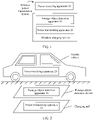
- FIG. 1 is a schematic diagram of an architecture of a wireless power transmission system according to an embodiment of this application.
- the wireless power transmission system may include a power transmitting apparatus 10, a power receiving apparatus 20, and a foreign object detection apparatus 30.
- the power receiving apparatus 20 may be disposed in a powered device.
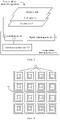
- FIG. 2 and FIG. 3 show schematic diagrams of two application scenarios of the wireless power transmission system.
- the powered device may be an electrically driven vehicle shown in FIG. 2 , or may be a mobile terminal shown in FIG. 3 .
- the electrically driven vehicle may be an electric vehicle, an electric bicycle, or the like.
- an electric vehicle is used as an example for illustrative description.
- the mobile terminal may be a mobile phone, a tablet computer, an intelligent wearable device, or the like.
- a mobile phone is used as an example for illustrative description.
- the power transmitting apparatus 10 is disposed in a charging device.
- the charging device may be a non-portable charging pad shown in FIG. 2 , or may be a portable charger shown in FIG. 3 .
- the charging pad may be disposed in a region such as a wireless charging station, a wireless charging parking space, or a wireless charging road.
- the charging pad may be disposed on a ground, or may be buried underground. In FIG. 2 , an example in which the charging pad is buried underground is used for illustrative description.
- the powered device is not limited to the electrically driven vehicle and the mobile terminal described above, and may be another electronic device supporting wireless charging, for an example, an electric robot.
- the charging device is not limited to the charging pad and the charger described above. Types of the powered device and the charging device are not specifically limited in this embodiment.
- the power transmitting apparatus 10 and the power receiving apparatus 20 may transmit energy to each other in an electromagnetic induction manner.
- the power transmitting apparatus 10 may be connected to a power source, and the power receiving apparatus 20 may be connected to a power supply of a to-be-charged device. After the to-be-charged device enters a wireless charging range of the power transmitting apparatus 10, a wireless charging system is enabled, and the power source may charge the power supply of the to-be-charged device by using the power transmitting apparatus 10 and the power receiving apparatus 20.
- the power transmitting apparatus 10 may include a transmit coil and a transmit control circuit connected to the transmit coil.
- the transmit coil and resonance elements such as an inductor and a capacitor may constitute a resonance circuit, to improve transmission efficiency.
- the transmit control circuit may provide a high-frequency alternating current for the transmit coil, so that the transmit coil generates an alternating magnetic field, and transmits energy through the alternating magnetic field.
- the transmit control circuit is connected to the power source, and the power source may be an alternating current power supply to reduce complexity of a circuit structure, or may be a direct current power supply to reduce costs.
- the transmit control circuit may convert a direct current generated by the power source into a high-frequency alternating current by using an inverter circuit.
- the power receiving apparatus 20 may include a receive coil and a receive control circuit connected to the receive coil.
- the receive coil is coupled to the transmit coil, and may receive energy through the alternating magnetic field generated by the transmit coil, so as to generate an induced current or voltage.
- the receive control circuit may convert, by using a rectifier circuit or the like, the induced current or voltage generated by the transmit coil into a direct current or voltage, so as to charge the power supply of the to-be-charged device.
- the power transmitting apparatus 10 and the power receiving apparatus 20 may further include other modules, such as a communication module and a storage module. Specific structures of the power transmitting apparatus 10 and the power receiving apparatus 20 are not specifically limited in this embodiment.
- the foreign object detection apparatus 30 is disposed between the power transmitting apparatus 10 and the power receiving apparatus 20.
- the foreign object detection apparatus 30 may be disposed on a power receiving side.
- the foreign object detection apparatus 30 may alternatively be disposed on a charging side, to form the wireless charging system jointly with the power transmitting apparatus 10.
- the power transmitting apparatus 10 and the foreign object detection apparatus 30 may be disposed in different devices.
- the power transmitting apparatus 10 is disposed in the charging pad, and the foreign object detection apparatus 30 is disposed in a foreign object detection device above the charging pad.
- the power transmitting apparatus 10 and the foreign object detection apparatus 30 may be disposed in a same device.
- the power transmitting apparatus 10 and the foreign object detection apparatus 30 both are disposed in the charger.
- the power transmitting apparatus 10 and the foreign object detection apparatus 30 may be disposed in a same device, that is, both may be disposed in the charging pad.
- FIG. 2 an example in which the power transmitting apparatus 10 and the foreign object detection apparatus 30 are disposed in different devices is used only for illustrative description instead of limiting this application.
- FIG. 4 is a schematic diagram of a structure of a foreign object detection apparatus according to an embodiment of this application.
- the foreign object detection apparatus 30 may include a coil array 31 and a foreign object detection circuit 32.
- the coil array 31 may be laid between the transmit coil and the receive coil.
- a laying plane of the coil array 31 may be parallel to a laying plane of the transmit coil, and a projection of a center of the coil array 31 on the laying plane of the transmit coil may overlap a center of the transmit coil.
- a coverage area of the coil array 31 may be greater than or equal to a coverage area of the transmit coil, so that foreign object detection can be performed on a detection region corresponding to the entire transmit coil (that is, a projection region of the transmit coil in a direction toward the receive coil).
- the coil array 31 may be disposed on a ground, or may be buried underground.
- FIG. 5 is a schematic diagram of a structure of a coil array according to an embodiment of this application.
- the coil array 31 may include a plurality of detection coils 311 arranged in a matrix, and the detection coils 311 may have a same material, a same quantity of turns, and a same winding manner.
- the detection coil 311 may be specifically wound into a rectangular structure, to eliminate a star-shaped coverage hole between circular coils.
- the detection coil 311 may be formed by winding a wire, or may be formed by using a printed circuit board (PCB) coil, to reduce an error generated in a coil winding process.
- PCB printed circuit board
- FIG. 6 is a schematic diagram of a structure of a detection coil according to an embodiment of this application.
- the detection coil 311 may be a coil structure with uniform turn density, that is, turns are arranged at an equal spacing. This winding manner is relatively simple.
- a turn spacing in the edge region of the detection coil 311 may be greater than a turn spacing in a middle region thereof.
- a turn spacing of the detection coil 311 increases progressively outside in. In this way, detection sensitivity in the edge region of the detection coil 311 can be improved.
- a turn in the edge region of the detection coil 311 has greater impact on magnetic field strength than a turn in the middle region.
- Magnetic field strength increased by adding one turn of coil in the edge region of the detection coil 311 is equivalent to that increased by adding a plurality of turns of coil in the middle region.
- an increase of a quantity of turns of coil may increase an impedance of the detection coil 311.
- increasing a quantity of turns of coil in the middle region causes a higher impedance. Therefore, a smaller turn spacing is used in the edge region of the detection coil 311, and a larger turn spacing is used in the middle region. This not only can improve detection sensitivity of the detection coil 311, but also can reduce the impedance of the detection coil 311, thereby reducing power consumption of the detection coil 311. It can be understood that, FIG. 6 is merely an example, and is not used to limit this application.
- the detection coil 311 may be divided into two parts outside in: an edge region with a first width and a middle region with a second width. Turns in the edge region are arranged at an equal spacing (a first turn spacing), and turns in the middle region are arranged at an equal spacing (a second turn spacing).
- an arrangement manner of the detection coil 311 may be selected based on a requirement, and is not specifically limited in this embodiment.
- each detection coil 311 is electrically connected to a foreign object detection circuit 32.
- the detection coil 311 in the coil array 31 may generate an induction signal due to action of an environmental magnetic field (that is, the magnetic field between the transmit coil and the receive coil).
- an environmental magnetic field that is, the magnetic field between the transmit coil and the receive coil.
- the induction signal of the detection coil 311 changes due to the foreign object.
- the foreign object detection circuit 32 may detect, based on the induction signals generated by the detection coils 311, whether there is a foreign object in a detection region corresponding to the coil array 31.
- the detection coils 311 in the coil array 31 that are symmetrical to each other relative to a row center line or a column center line are subject to basically same strength and distribution that are of an environmental magnetic field.
- induction signals generated by these detection coils 311 symmetrical to each other are also basically the same.
- Foreign object detection may be performed by using this feature, to reduce algorithm complexity.
- a quantity of rows and a quantity of columns of the detection coils 311 in the coil array 31 each may be specifically an even number.
- at least one of the quantity of rows in the coil array 31 and the quantity of columns in the coil array 31 may be a multiple of four, to improve sensitivity of foreign object detection.
- FIG. 5 an example in which the quantity of rows and the quantity of columns each are four is used for illustrative description.
- the detection coils 311 originate from the environmental magnetic field, that is, a magnetic field generated by charging coils (including the transmit coil and the receive coil) is a unique excitation source, when there is no excitation, the foreign object detection apparatus 30 cannot detect an existing foreign object.
- detection accuracy is mainly determined by the environmental magnetic field.
- the strength and the distribution of the environmental magnetic field are non-linear and non-uniform, and may change. These factors may affect accuracy of a detection result.
- excitation source-based detection may be used, that is, the foreign object detection circuit 32 may provide an alternating current excitation signal to each detection coil 311, so that strength of the induction signal of each detection coil 311 is mainly subject to the excitation signal provided by the foreign object detection circuit 32.
- a main difference between the excitation source-based detection and excitation source-free detection lies in that the induction signal of each detection coil 311 in the excitation source-based detection has stronger strength. Processes of foreign object detection in these two manners are similar.
- the excitation source-based detection is used as an example for subsequent illustrative description.
- each detection coil 311 in the coil array 31 is affected by a magnetic field of a surrounding detection coil.
- foreign object detection is performed based on the symmetry of the detection coils.
- a wiring structure used by the detection coil 311 in the coil array 31 may include but is not limited to the following two manners.
- the detection coils 311 in the array have a same wiring structure.
- each detection coil 311 is wound clockwise, and an outer terminal faces upward.
- the coil array 31 may be divided into four quadrants based on the row center line and the column center line of the coil array 31.
- Detection coils 311 in a same quadrant have a same wiring structure, and wiring structures of the detection coils 311 in adjacent quadrants are symmetrical to each other relative to a center line between the adjacent quadrants.
- each detection coil 311 in a second quadrant in an upper left corner is wound clockwise, and an outer terminal faces upward.
- a wiring structure of a detection coil 311 in a first quadrant in an upper right corner is symmetrical to that of the detection coil 311 in the second quadrant relative to the column center line of the coil array 31, each detection coil 311 in the first quadrant is wound counterclockwise, and an outer terminal faces upward.
- a wiring structure of a detection coil 311 in a third quadrant in a lower left corner is symmetrical to that of the detection coil 311 in the second quadrant relative to the row center line of the coil array 31, each detection coil 311 in the third quadrant is wound counterclockwise, and an outer terminal faces downward.
- a wiring structure of a detection coil 311 in a fourth quadrant in a lower right corner is symmetrical to that of the detection coil 311 in the third quadrant relative to the column center line of the coil array 31, each detection coil 311 in the fourth quadrant is wound clockwise, and an outer terminal faces downward.
- the wiring structure of the detection coil 311 in the fourth quadrant is further symmetrical to that of the detection coil 311 in the first quadrant relative to the row center line of the coil array 31.
- the wiring structure in the first manner can enable two detection coils 311 in the coil array 31 that are symmetrical to each other relative to the row center line or the column center line of the coil array 31 to be subject to a same environmental magnetic field, and this structure is relatively simple and easy to prepare.
- the wiring structure in the second manner can enable two detection coils 311 in the coil array 31 that are symmetrical to each other relative to the row center line or the column center line of the coil array 31 to be subject to a same magnetic field of a surrounding detection coil.
- a wiring structure of each detection coil 311 in the coil array 31 may be selected based on a requirement, and is not specifically limited in this embodiment.
- the foreign object detection circuit 32 may include an excitation source 321, a signal obtaining unit 322, and a signal processing unit 323.
- a power source of the excitation source 321 is similar to that of the power transmitting apparatus 10.
- An alternating current power supply may be directly used to provide an alternating current (that is, an excitation signal) to the detection coil 311.
- a direct current power supply and an inverter circuit are used, and a direct current generated by the direct current power supply is converted into a high-frequency alternating current by using the inverter circuit, so as to reduce costs.
- a voltage of the excitation source 321 may be selected based on a requirement, for example, may be 4 V or 12 V.
- the detection coils 311 may not be connected in series, so as to avoid impact of a parasitic parameter caused by the serial connection on a detection result.
- the detection coils 311 may not be connected in parallel, that is, each detection coil 311 provides an excitation signal by using an independent excitation source, so as to reduce a requirement of the circuit on the excitation source.
- a signal value of the induction signal, of the detection coil 311, that is obtained by the signal obtaining unit 322 may include at least one of the following: a voltage (which may be a valid value, a transient value, a peak value, or an amplitude), a current, an impedance, a phase, or the like.
- the signal obtaining unit 322 may collect the induction signal of each detection coil 311, or may obtain the induction signal of each detection coil 311 through another circuit. In this embodiment, an example in which the signal obtaining unit 322 actively collects the induction signal of each detection coil 311 is used for subsequent illustrative description.
- the signal processing unit 323 may control the excitation source 321 to provide an excitation signal, and may obtain the induction signal obtained by the signal obtaining unit 322, to perform foreign object detection based on the obtained induction signal
- a structure of the foreign object detection circuit 32 is not limited to the structure shown in FIG. 4 .
- the induction signal obtained by the signal obtaining unit 322 may further be amplified, filtered, and then output to the signal processing unit 323, so that the signal processing unit 323 performs foreign object detection by using the induction signal.
- the foreign object detection circuit 32 may further include other circuit modules such as a signal amplification circuit and a signal filtering circuit.
- a specific circuit structure of the foreign object detection circuit 32 is not specifically limited in this embodiment.
- Each circuit structure included in the foreign object detection circuit 32 may be implemented in a manner of hardware, software, or a combination of software and hardware, and a plurality of circuit structures may also be integrated in a same component.
- a signal value of the obtained induction signal of the detection coil 311 may be compared with a preset signal threshold, to determine whether the induction signal of the detection coil 311 is abnormal, and further determine whether there is a foreign object in the detection region corresponding to the detection coil 311.
- a system parameter may change, for example, charging power is adjusted.
- the foreign object detection apparatus 30 may also be interfered with by an environment. For example, when the foreign object detection apparatus 30 is buried underground, the coil array 31 may be interfered with by a concrete layer and a protective housing. Consequently, validity of the preset signal threshold decreases, and the signal threshold needs to be changed. However, after the foreign object detection apparatus 30 is packaged and buried underground, the internal preset signal threshold is hard to correct. Based on this, in this embodiment, when foreign object detection is performed, an abnormal-value threshold may be dynamically determined based on the obtained induction signal.
- an inherent error for example, an error caused by an interference factor such as the power adjustment, the concrete layer, or the protective housing described above
- foreign object detection is performed based on the abnormal-value threshold, so that an anti-interference capability and environment adaptability of foreign object detection can be improved.
- a signal threshold may be determined based on the obtained induction signal, and foreign object detection may be performed based on the signal threshold subsequently. The following describes a foreign object detection process.
- foreign object detection is performed based on the symmetry of the detection coils.
- the detection coils in the coil array 31 that are symmetrical to each other relative to the row center line or the column center line are subject to substantially same strength and distribution of the environmental magnetic field. Therefore, in specific implementation, four detection coils in the coil array 31 whose locations are symmetrical to each other (that is, two detection coils in the coil array 31 that are symmetrical to each other relative to the row center line and two detection coils that are symmetrical to the foregoing two detection coils relative to the column center line) may serve as one coil group, and foreign object detection is performed in a unit of a coil group. In other words, the four detection coils in each coil group are arranged in a 2 ⁇ 2 array. Two detection coils in a same row of one coil group are symmetrically distributed relative to the column center line of the coil array 31, and two detection coils in a same column of one coil group are symmetrically distributed relative to the row center line of the coil array 31.
- a coil group A includes detection coils A1, A2, A3, and A4
- a coil group B includes detection coils B1, B2, B3, and B4
- a coil group C includes detection coils C1, C2, C3, and C4
- a coil group D includes detection coils D1, D2, D3, and D4.
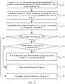
- FIG. 9 is a schematic flowchart of a foreign object detection method according to an embodiment of this application. As shown in FIG. 9 , the method may include the following steps.
- a foreign object detection circuit may output a same alternating current excitation signal to each detection coil in the coil array.
- a signal value of the obtained induction signal of the detection coil may include at least one type of the foregoing signal values, such as a voltage, a current, an impedance, and a phase.
- the signal value of the obtained induction signal of the detection coil includes an amplitude and a phase of the detection coil.
- a phase difference between the detection coils in the coil group may be obtained during specific obtaining to perform foreign object detection. For example, phase differences between each detection coil in the coil group and the other detection coils in the coil group may be collected, or a phase difference between adjacent detection coils in the coil group may be collected.
- the signal value of the obtained detection signal may include: an amplitude of each detection coil in the coil group and a phase difference of each pair of adjacent detection coils in the coil group. This is used as an example in this embodiment for subsequent illustrative description of a foreign object detection process.
- an induction signal in a preset time period (referred to as a first time period herein) may be obtained.
- the first time period there may be a plurality of signal values for the obtained induction signal of each detection coil, so as to improve accuracy of a detection result.
- the first time period may be preset duration, or may be determined in advance based on a quantity of to-be-obtained signal values of the induction signal, that is, may be duration required for obtaining a preset quantity (for example, 100) of signal values.
- the alternating current excitation signal may be continuously output in parallel to each detection coil.
- induction signals generated by the detection coils are collected in parallel, or detection coils in each coil group may be successively selected to collect induction signals.
- a manner of collecting the induction signals in parallel has higher real-time performance, and a manner of successively collecting the induction signals can reduce power consumption.
- the manners may be selected based on a requirement in actual application. This is not specifically limited in this embodiment.
- the manner of successively collecting the induction signals is used as an example for subsequent illustrative description of a technical solution in this application.
- coil groups may be successively selected in a preset sequence (referred to as a first preset sequence herein) in the first time period, so that the alternating current excitation signal is output to a selected coil group, and induction signals are collected.
- a first preset sequence referred to as a first preset sequence herein
- excitation signal output and induction signal collection may be successively performed on the coil groups according to a sequence of A ⁇ B ⁇ C ⁇ D.
- detection coils in the coil group may be successively selected according to a preset sequence (referred to as a second preset sequence herein), so that the alternating current excitation signal is output to a selected detection coil, and an induction signal is collected.
- a preset sequence referred to as a second preset sequence herein
- pairs of detection coils may be successively selected according to a sequence of A1A2 ⁇ A2A3 ⁇ A3A4 ⁇ A4A1, so that excitation signal output and induction signal collection are performed on selected detection coils.
- S120 Determine an abnormal-value threshold of each coil group based on induction signals that are of each coil group and that are obtained in the first time period, and detect, based on the abnormal-value threshold of each coil group and the induction signals that are of each coil group and that are obtained in the first time period, whether there is a foreign object in a detection region corresponding to the coil array.
- each detection coil there may be a plurality of signal values for the induction signal that is of the detection coil and that is obtained in the first time period.
- the coil group A is used as an example.
- amplitudes and phase differences in k periods may be obtained, and stored in an array A 12 (step S1).
- the array A 12 includes k groups of data, and each group of data includes an amplitude of A1, an amplitude of A2, and a phase difference between A1 and A2.
- the phase difference between A1 and A2 may be a difference obtained by subtracting a phase of one of A1 and A2 from a phase of the other of A1 and A2, or may be an absolute value of the phase difference between A1 and A2.
- Each signal value in the array A 12 may be labeled, and a corresponding detection coil is identified by using a label.
- the signal value may alternatively be determined based on a plurality of sampled values in one sampling period. For example, for the amplitude of A1, sampling may be performed for a plurality of times in each of the k periods, and an average of sampled values is used as the amplitude of A1 that is obtained in the period. In this manner, impact of a circuit signal fluctuation on an obtained result can be reduced.
- a data obtaining manner of detection coils in the coil group A that are selected at another time is similar to that of the detection coils A1 and A2, and detection coils selected each time correspond to one array.
- the detection coils A2 and A3 correspond to an array A 23
- the detection coils A3 and A4 correspond to an array A 34
- the detection coils A4 and A1 correspond to an array A 41 (step S2).
- detection coils in one coil group receive a same alternating current excitation signal, and are subject to substantially same strength and distribution of an environmental magnetic field.
- induction signals generated by the detection coils are substantially the same.
- An abnormal-value detection algorithm for example, an interquartile range method
- the abnormal-value detection algorithm may alternatively be an algorithm other than the interquartile range method, for example, a median method, an averaging method, or a clustering method.
- the interquartile range method is simple and effective. The following uses this algorithm as an example to describe an abnormal-value detection process for the coil group A.
- each array corresponding to the coil group A includes: 8 ⁇ k (namely, 8k) amplitudes (amplitudes in 2 ⁇ k (namely, 2k) periods are obtained for each detection coil in the coil group A) and 4 ⁇ k (namely, 4k) phase differences.
- the amplitude is used as an example.
- the 8k amplitudes may be sorted in ascending order. Then, an obtained sequence may be divided into four equal parts.
- a value at a location of a division point is a quartile, and three quartiles may be obtained: a first quartile (Q1), a second quartile (Q2, that is, a median), and a third quartile (Q3).
- An interquartile range (IQR) is: Q3-Q1.
- a normal data range is [Q1-n ⁇ IQR, Q3+n ⁇ IQR]. It may be determined, based on the range, whether there is an abnormal value in the 8k amplitudes (step S4). An amplitude that falls outside the range is an abnormal value.
- the abnormal-value threshold may include a first threshold (Q1-n ⁇ IQR) and a second threshold (Q3+n ⁇ IQR), and a signal value that is less than the first threshold or greater than the second threshold is an abnormal value.
- n may be set based on a sensitivity requirement, for example, may be 1.5.
- An abnormal-value determining process for the phase differences is similar to that for the amplitudes, and an abnormal-value determining process for another coil group is similar to that for the coil group A. Details are not described herein.
- foreign object determining for each coil group, if the induction signals of the coil group have no abnormal value, it can be considered that there is no foreign object in a detection region corresponding to the coil group, or if the induction signals of the coil group have an abnormal value, it can be considered that there is a foreign object in the detection region corresponding to the coil group.
- a case of an environment exception may exist, for example, when a charging power fluctuates at an initial stage after charging starts, a magnetic field in which the coil array is located may be affected by such a case, and consequently, the induction signal of each detection coil in the coil array is affected. Therefore, to improve accuracy of a detection result, in another optional implementation in this embodiment, for each coil group, if the induction signals of the coil group have an abnormal value, a working status of another coil group may be checked, that is, whether induction signals of the another coil group also have an abnormal value may be checked (step S5).
- all the induction signals of the coil group each have an abnormal value, it can be considered that an environment exception occurs; or otherwise, it can be considered that there is a foreign object in a detection region corresponding to the coil group.
- the induction signals of each coil group each have an abnormal value, it can be considered that an environment exception occurs, and there is no foreign object in the detection region corresponding to the coil array.
- the induction signals of each coil group each have no abnormal value, it can be considered that there is no foreign object in the detection region corresponding to the coil array, and no environment exception occurs.
- induction signals of at least one of the coil groups have an abnormal value
- induction signals of at least one of the coil groups have no abnormal value, it can be considered that there is a foreign object in the detection region corresponding to the coil array.
- foreign object determining manner is only an example, and is not used to limit this application.
- another manner may alternatively be used, for example, foreign object determining is performed with reference to an abnormal-value proportion. This is not specifically limited in this embodiment.
- a subsequent detection process may continue. If an environment exception occurs, that is, the induction signals of all the coil groups each have an abnormal value, induction signals in one another first time period (that is, a next first time period) may be obtained. Abnormal-value detection is performed based on the induction signals obtained in the next first time period (step S6). If no environment exception occurs, that is, the induction signals of each coil group each have no abnormal value, a subsequent step may be performed to determine a signal threshold of each coil group (step S8).
- an alarm may be reported and charging may be stopped (step S7). Further, it can be determined, based on a detection coil corresponding to the abnormal value, a specific detection coil whose corresponding detection region has a foreign object. During alarm reporting, a location of the foreign object may be indicated in a voice manner and/or an image display manner. For example, if the abnormal value is an amplitude of the detection coil A1, it indicates that there is a foreign object in a detection region corresponding to the detection coil A1.
- the abnormal value includes the phase difference between the detection coils A1 and A2 and a phase difference between A2 and A3, and both a phase difference between A3 and A4 and a phase difference between A4 and A1 are normal values, it indicates that there is a foreign object in a detection region corresponding to the detection coil A2.
- a signal threshold of the coil group may be determined. The following still uses the coil group A as an example for description.
- signal values of the induction signals that are of the coil group A and that are obtained in the first time period include an amplitude and a phase difference.
- a signal threshold of this type of signal value may be determined by using an averaging method. For example, all of this type of signal values that are of the coil group A and that are obtained in the first time period may be averaged, and an average value may be used as the signal threshold of this type of signal values. The foregoing example is still used.
- An amplitude threshold of the coil group A is an average value of the 8k amplitudes included in the arrays corresponding to the coil group A
- a phase difference threshold of the coil group A is an average value of the 4k phase differences included in the arrays corresponding to the coil group A.
- the foregoing signal threshold determining method is only a relatively simple method.
- another method such as a weighted averaging method or a median method may alternatively be used to determine the signal threshold. This is not specifically limited in this embodiment.
- a signal threshold determining manner of another coil group is similar to that of the coil group A, and details are not described herein. It can be understood that, for each coil group, the signal threshold may be determined when it is determined that the induction signals of the coil group have no abnormal value, or when it is determined that the induction signals of each coil group each have no abnormal value. In this way, if induction signals of another coil group have an abnormal value, there is no need to determine a signal threshold again, thereby saving a processing resource.
- S140 Detect, for at least one second time period after the first time period based on the signal threshold of each coil group and induction signals that are of each coil group and that are obtained in the second time period, whether there is a foreign object in the detection region corresponding to the coil array.
- subsequent foreign object detection may be performed based on the signal threshold.
- induction signals generated by the detection coils may be collected in parallel, or detection coils in each coil group may be successively selected to collect induction signals.
- detection coils in each coil group may be successively selected to collect induction signals.
- there may be a plurality of signal values for the induction signal that is of the detection coil and that is obtained in the second time period.
- the coil group A is still used as an example.
- amplitudes and phase differences in k' periods may be obtained.
- 8k' amplitudes (amplitudes in 2k' periods are obtained for each detection coil in the coil group A) and 4k' phase differences can be obtained.
- a signal value in each period may be an average value of a plurality of corresponding sampled values.
- k' may be equal to k, or may be less than k, so as to improve detection real-time performance.
- each obtained amplitude may be compared with the amplitude threshold of the coil group A, and each obtained phase difference may be compared with the phase difference threshold of the coil group A, so as to determine whether each amplitude and each phase difference are abnormal, and further determine whether the coil group A works abnormally.
- the 2k' amplitudes of each detection coil or the amplitudes in the k' periods that are obtained in one selection process may be averaged to obtain an average value, which is then compared with the amplitude threshold of the coil group A, and the k' phase differences of each pair of adjacent detection coils may be averaged to obtain an average value, which is then compared with the phase difference threshold of the coil group A, so as to determine whether each average amplitude value and each average phase difference value are abnormal, and further determine whether the coil group A works abnormally. In this way, processing efficiency can be improved, and impact of a circuit signal fluctuation on a detection result can be reduced.
- determining on whether an average value of each type of signal values is abnormal in an example of amplitudes, it may be determined whether an absolute value of a difference between an average amplitude value and the amplitude threshold exceeds a preset value (referred to as a first preset value herein). If the absolute value exceeds the preset value, it is considered that the average amplitude value is abnormal, that is, there is an abnormal value in the amplitudes corresponding to the average amplitude value. If the average amplitude value does not exceed the preset value, it is considered that the average amplitude value is normal, that is, there is no abnormal value in the amplitudes corresponding to the average amplitude value.
- the first preset value may be determined based on required detection precision. An exception determining manner for a phase difference is similar to that for an amplitude, and details are not described herein. It can be understood that, exception determining may alternatively be performed in another manner. This is not specifically limited in this embodiment.
- each average amplitude value and each average phase difference value of the coil group A are both normal, it can be considered that the coil group A works normally; or otherwise, it can be considered that the coil group A works abnormally.
- a case of an environment exception may exist, for example, when a parking deviation occurs or a charging power changes, a magnetic field in which the coil array is located may be affected by such a case. Therefore, to improve accuracy of a detection result, in another optional implementation in this embodiment, for each coil group, if the coil group works abnormally, a working status of another coil group may be checked. If all coil groups work abnormally, it can be considered that an environment exception occurs; or otherwise, it can be considered that there is a foreign object in the detection region corresponding to the coil group.
- each coil group works normally or works abnormally, that is, the induction signals of each coil group each have no abnormal value or each have an abnormal value, it can be considered that there is no foreign object in the detection region corresponding to the coil array. If at least one of the coil groups works normally, and at least one of the coil groups works abnormally, that is, induction signals of at least one of the coil groups have an abnormal value, and induction signals of at least one of the coil groups have no abnormal value, it can be considered that there is a foreign object in the detection region corresponding to the coil array.
- the foregoing foreign object determining manner is only an example, and is not used to limit this application.
- another manner may alternatively be used, for example, foreign object determining is performed with reference to an abnormal-value proportion. This is not specifically limited in this embodiment.
- induction signals in a next second time period may be further obtained, to perform foreign object detection. If it is determined that there is a foreign object in the detection region corresponding to the coil array, an alarm may be reported and charging may be stopped. Further, it can be determined, based on a detection coil corresponding to the abnormal value, a specific detection coil whose corresponding detection region has a foreign object. During alarm reporting, a location of the foreign object may be indicated in a voice manner and/or an image display manner.
- the foreign object detection method used in step S120 may be further used.
- the algorithm is simpler, and a case in which there is a foreign object in a center location of the coil array may be effectively detected.
- the abnormal-value detection algorithm such as the interquartile range method is still used to perform foreign object detection, an exception cannot be detected.
- foreign object detection is performed by using the signal threshold, it can be effectively determined that each detection coil in the middle coil group works abnormally, so that it is determined that there is a foreign object in the center location of the coil array.
- an amplitude may be replaced with an amplitude difference.
- the amplitude threshold of the coil group in step S130 is correspondingly replaced with an amplitude difference threshold.
- the signal threshold may also be updated in a subsequent detection process, to further improve environment adaptability of foreign object detection.
- the signal threshold of each coil group may be updated, or the signal threshold of each coil group may be updated only when an environment exception occurs. In other words, for a second time period, if it is determined that there is no foreign object in the detection region corresponding to the coil array and no environment exception occurs, the signal threshold of each coil group does not need to be updated, so as to save a processing resource.
- averaging or weighted averaging may be performed on amplitudes that are of the coil group A and that are obtained in the second time period and the amplitude threshold, and an obtained result is used as an updated amplitude threshold.
- a method for updating a phase difference threshold and a signal threshold of another coil group is similar to the foregoing method for updating the amplitude threshold, and details are not described herein. It can be understood that, the method for updating a signal threshold is not limited to the foregoing method. The foregoing updating method is merely an example, and is not used to limit this application. The method for updating a signal threshold in this embodiment is not specifically limited.
- the transmit coil before the transmit coil transmits power to the receive coil, whether there is a foreign object in the detection region corresponding to the coil array may be detected. When it is determined that there is no foreign object in the detection region corresponding to the coil array, the transmit coil is then controlled to transmit power to the receive coil.
- a foreign object detection method used before charging may be similar to the foreign object detection method used in the first time period, that is, foreign object detection may be performed by using a method such as the interquartile range method.
- a method such as the interquartile range method.
- a difference lies in that an environment exception may be not considered when foreign object detection is performed.
- the induction signals of the coil group each have no abnormal value, it can be considered that there is no foreign object in the detection region corresponding to the coil group, or if the induction signals of the coil group have an abnormal value, it can be considered that there is a foreign object in the detection region corresponding to the coil group.
- the foreign object detection circuit may also pre-store a set of signal values (referred to initial values herein) of induction signals of each coil group in an ideal case (that is, a case that charging has not started and there is no foreign object in the environment).
- signal values of the induction signals of the coil group may be compared with the corresponding initial values, to determine whether the induction signals of the coil group have an abnormal value. If the induction signals of the coil group each have no abnormal value, it can be determined that there is no foreign object in the detection region corresponding to the coil group.
- each type of signal values of the induction signals of each coil group have a corresponding initial value.
- Specific determining on whether the induction signals of the coil group have an abnormal value is similar to the determining, based on the signal threshold, whether the induction signals have an abnormal value in step S140.
- the second preset value may be greater than the first preset value.
- a foreign object detection apparatus is disposed in the wireless charging system. After charging starts, the induction signal generated by each detection coil is obtained. Then, the abnormal-value threshold of each coil group is determined based on the induction signals that are of each coil group and that are obtained in the first time period. The first time period is a preset time period after the induction signals start to be obtained. Afterwards, it is detected, based on the abnormal-value threshold and the induction signals of each coil group, whether there is a foreign object in the detection region corresponding to the coil array. In this way, when a foreign object is detected, the foreign object can be removed in time, thereby improving wireless charging safety and charging efficiency.
- the abnormal-value threshold is dynamically determined based on the obtained induction signals, and foreign object detection is performed based on the abnormal-value threshold.
- an inherent error for example, an error caused by an interference factor such as a power adjustment, a concrete layer, or a protective housing
- an anti-interference capability and environment adaptability of foreign object detection can be improved.
- foreign object detection is performed based on symmetry of the detection coils in a unit of a coil group. This can reduce algorithm complexity.
- the foreign object detection circuit may provide the alternating current excitation signal to each detection coil, that is, use excitation source-based detection.
- strength of the induction signal of each detection coil is mainly subject to an excitation source. This can reduce impact of the environmental magnetic field on detection accuracy, and further improve accuracy of foreign object detection.
- the signal threshold is determined based on the induction signals obtained in the first time period, and subsequent foreign object detection is performed based on the signal threshold, thereby increasing a processing speed.
- the signal threshold may be updated in a subsequent detection process, so that environment adaptability of foreign object detection can be further improved.
- FIG. 11 is a schematic diagram of a structure of a foreign object detection device according to an embodiment of this application.
- the foreign object detection device may include a coil array 110, a processor 120, a memory 130, a communication module 140, an audio module 150, and a display 160.
- the foreign object detection device may include more or fewer components than those shown in the figure, or combine some components, or split some components, or have different component arrangements.
- the components shown in the figure may be implemented by using hardware, software, or a combination of software and hardware.
- the processor 120 may be a central processing unit (CPU), or may be another general-purpose processor 120, a digital signal processor (DSP) 120, an application-specific integrated circuit (ASIC), a field programmable gate array (FPGA), or another programmable logic device, a discrete gate or a transistor logic device, a discrete hardware component, or the like.
- the general-purpose processor 120 may be a microprocessor 120, or the processor 120 may be any conventional processor 120. Some or all of the foregoing circuit modules of the foreign object detection circuit may be integrated into the processor 120.
- the memory 130 is configured to store instructions and data (for example, induction signals collected by a signal collection unit).
- the memory 130 may include a non-persistent memory 130, a random access memory 130 (RAM), a non-volatile memory, and/or another form in a computer-readable medium, for example, a read-only memory 130 (ROM) or a flash memory (flash RAM).
- the memory 130 may include a volatile memory and/or a non-volatile memory.
- the non-volatile memory may be a read-only memory (ROM), a programmable read-only memory (PROM), an erasable programmable read-only memory 130 (EPROM), an electrically erasable programmable read-only memory (EEPROM), or a flash memory (flash).
- the volatile memory may be a random access memory (RAM) that is used as an external cache.
- RAM random access memory
- various forms of RAMs may be used, such as a static random access memory (SRAM), a dynamic random access memory (DRAM), a synchronous dynamic random access memory (SDRAM), and a double data rate synchronous dynamic random access memory (DDR SDRAM).
- the foreign object detection device may communicate with a power transmitting apparatus, a power receiving apparatus, and/or another device by using the communication module 140.
- the communication module 140 may provide wireless communication solutions that are applied to a foreign object detection apparatus, including a wireless local area network (WLAN) (for example, a wireless fidelity (Wi-Fi) network), Bluetooth (BT), a global navigation satellite system (GNSS), frequency modulation (FM), near field communication (NFC), and infrared (IR).
- WLAN wireless local area network
- Wi-Fi wireless fidelity
- BT Bluetooth
- GNSS global navigation satellite system
- FM frequency modulation
- NFC near field communication
- IR infrared
- the audio module 150 may provide a sound signal, and the foreign object detection device may report an alarm in a voice manner in the foregoing method embodiments by using the audio module 150.
- the display 160 is configured to display an image, a video, and the like.
- the foreign object detection device may display a location of a foreign object in a coil array by using the display 160.
- the display 160 includes a display panel.
- the display panel may be a liquid crystal display (LCD), an organic light-emitting diode (OLED), an active-matrix organic light-emitting diode (AMOLED), a flexible light-emitting diode (FLED), a mini LED, a micro LED, a quantum dot light-emitting diode (QLED), or the like.
- LCD liquid crystal display
- OLED organic light-emitting diode
- AMOLED active-matrix organic light-emitting diode
- FLED flexible light-emitting diode
- mini LED a micro LED
- QLED quantum dot light-emitting diode
- the foreign object detection device provided in this embodiment may perform the foregoing method embodiments.
- An implementation principle and a technical effect thereof are similar to those of the foregoing method embodiments, and details are not described herein.
- An embodiment of this application further provides a computer-readable storage medium.
- a computer program is stored on the computer-readable storage medium.
- the computer program is executed by a processor, the method in the foregoing method embodiments is implemented.
- An embodiment of this application further provides a computer program product.
- the computer program product runs on an electronic device, the electronic device is enabled to perform the method in the foregoing method embodiments when executing the computer program product.
- An embodiment of this application further provides a chip system, including a processor.
- the processor is coupled to a memory, and the processor executes a computer program stored in the memory, to implement the method in the foregoing method embodiments.
- the chip system may be a single chip or a chip module including a plurality of chips.
- All or some of the foregoing embodiments may be implemented by using software, hardware, firmware, or any combination thereof.
- software is used to implement the embodiments, all or some of the embodiments may be implemented in a form of a computer program product.
- the computer program product includes one or more computer instructions. When the computer program instructions are loaded and executed on the computer, the procedure or functions according to embodiments of this application are all or partially generated.
- the computer may be a general-purpose computer, a dedicated computer, a computer network, or another programmable apparatus.
- the computer instructions may be stored in a computer-readable storage medium, or may be transmitted through the computer-readable storage medium.
- the computer instructions may be transmitted from a website, computer, server, or data center to another website, computer, server, or data center in a wired (for example, a coaxial cable, an optical fiber, or a digital subscriber line) or wireless (for example, infrared, radio, or microwave) manner.
- the computer-readable storage medium may be any usable medium accessible by the computer, or a data storage device, such as a server or a data center, integrating one or more usable media.
- the usable medium may be a magnetic medium (for example, a floppy disk, a hard disk, or a magnetic tape), an optical medium (for example, a DVD), a semiconductor medium (for example, a solid-state disk (SSD)), or the like.
- the program may be stored in the computer-readable storage medium.
- the storage medium may include any medium that can store program code, such as a ROM or a random access memory RAM, a magnetic disk, or a compact disc.
- Names or numbers of steps in this application do not mean that the steps in the method procedure need to be performed in a time/logical sequence indicated by the names or numbers.
- An execution sequence of the steps in the procedure that have been named or numbered can be changed based on a technical objective to be achieved, provided that same or similar technical effects can be achieved.
- the disclosed apparatus/device and method may be implemented in other manners.
- division into the module or unit is merely logical function division and may be other division in an actual implementation.
- a plurality of units or components may be combined or integrated into another system, or some features may be ignored or not performed.
- the displayed or discussed mutual couplings or direct couplings or communication connections may be implemented through some interfaces.
- the indirect couplings or communication connections between the apparatuses or units may be implemented in electronic, mechanical, or other forms.
- A/B may represent A or B.
- the term "and/or” in this application represents only an association relationship for describing associated objects and represents that three relationships may exist.
- a and/or B may represent the following three cases: Only A exists, both A and B exist, and only B exists, where A and B may be singular or plural.
- a plurality of' means two or more than two.
- At least one of the following or a similar expression thereof means any combination of these items, including any combination of a single item or a plurality of items.
- at least one of a, b, or c may represent a, b, c, a and b, a and c, b and c, or a and b and c.
- a, b, and c may be singular or plural.
- the term “if” may be interpreted as “when”, “once”, “in response to determining”, or “in response to detecting” depending on the context.
- the phrase “if it is determined” or “if the [described condition or event] is detected” may be interpreted as meaning “once determined” or “in response to determining” or “once the [described condition or event] is detected” or “in response to detecting the [described condition or event]” depending on the context.
- an embodiment or “some embodiments” or the like in the specification of this application means that one or more embodiments of this application include a specific feature, structure, or characteristic described with reference to the embodiment. Therefore, statements such as “in an embodiment”, “in some embodiments”, “in some other embodiments”, and “in other embodiments” that appear at different places in this specification do not necessarily mean referring to a same embodiment, instead, they mean “one or more but not all of the embodiments", unless otherwise specifically emphasized.
Landscapes
- Engineering & Computer Science (AREA)
- Power Engineering (AREA)
- Computer Networks & Wireless Communication (AREA)
- Transportation (AREA)
- Mechanical Engineering (AREA)
- Life Sciences & Earth Sciences (AREA)
- Remote Sensing (AREA)
- Physics & Mathematics (AREA)
- Electromagnetism (AREA)
- Environmental & Geological Engineering (AREA)
- Geology (AREA)
- General Life Sciences & Earth Sciences (AREA)
- General Physics & Mathematics (AREA)
- Geophysics (AREA)
- Geophysics And Detection Of Objects (AREA)
- Charge And Discharge Circuits For Batteries Or The Like (AREA)
Applications Claiming Priority (1)
| Application Number | Priority Date | Filing Date | Title |
|---|---|---|---|
| CN202110721532.4A CN113629890A (zh) | 2021-06-28 | 2021-06-28 | 异物检测方法、装置和无线充电系统 |
Publications (2)
| Publication Number | Publication Date |
|---|---|
| EP4113173A2 true EP4113173A2 (de) | 2023-01-04 |
| EP4113173A3 EP4113173A3 (de) | 2023-03-29 |
Family
ID=78378540
Family Applications (1)
| Application Number | Title | Priority Date | Filing Date |
|---|---|---|---|
| EP22181417.1A Pending EP4113173A3 (de) | 2021-06-28 | 2022-06-28 | Verfahren und vorrichtung zur fremdkörpererkennung und drahtloses ladesystem |
Country Status (3)
| Country | Link |
|---|---|
| US (1) | US11909228B2 (de) |
| EP (1) | EP4113173A3 (de) |
| CN (1) | CN113629890A (de) |
Family Cites Families (27)
| Publication number | Priority date | Publication date | Assignee | Title |
|---|---|---|---|---|
| US9270342B2 (en) * | 2011-12-16 | 2016-02-23 | Qualcomm Incorporated | System and method for low loss wireless power transmission |
| CN109969007A (zh) | 2012-10-19 | 2019-07-05 | 韦特里西提公司 | 无线能量传输系统中的外来物检测 |
| EP3086440B1 (de) * | 2013-12-05 | 2021-02-03 | Panasonic Intellectual Property Management Co., Ltd. | Arrayspulensystem |
| JP2015159690A (ja) | 2014-02-25 | 2015-09-03 | 株式会社東芝 | 異物検出装置、無線電力伝送装置、及び無線電力伝送システム |
| JP2015216828A (ja) | 2014-04-24 | 2015-12-03 | パナソニック株式会社 | 異物検出装置、無線送電装置、及び無線電力伝送システム |
| JP6248785B2 (ja) * | 2014-04-25 | 2017-12-20 | トヨタ自動車株式会社 | 送電装置および受電装置 |
| US10608477B2 (en) * | 2015-01-19 | 2020-03-31 | Ihi Corporation | Power transmission system, foreign object detection device, and coil device |
| US9829599B2 (en) * | 2015-03-23 | 2017-11-28 | Schneider Electric USA, Inc. | Sensor and method for foreign object detection in induction electric charger |
| CN106160268B (zh) | 2015-05-15 | 2020-11-06 | 松下知识产权经营株式会社 | 异物检测装置、无线送电装置以及无线电力传送系统 |
| EP3093957B1 (de) * | 2015-05-15 | 2022-05-18 | Panasonic Intellectual Property Management Co., Ltd. | Fremdkörperdetektionsvorrichtung, vorrichtung zur drahtlosen stromübertragung und system zur drahtlosen stromübertragung |
| US20200406860A1 (en) | 2015-07-17 | 2020-12-31 | Chao-Lun Mai | Method, apparatus, and system for vehicle wireless monitoring |
| DE102016103044A1 (de) * | 2016-02-22 | 2017-08-24 | Ipt Technology Gmbh | Verfahren zur Erkennung eines elektrisch leitfähigen Fremdkörpers |
| CN107306054B (zh) | 2016-04-25 | 2020-11-10 | 财团法人车辆研究测试中心 | 无线电力传输装置及其金属异物检测线圈的结构 |
| JP6784170B2 (ja) * | 2016-12-27 | 2020-11-11 | Tdk株式会社 | 金属異物検出装置、ワイヤレス給電装置、ワイヤレス受電装置、及びワイヤレス電力伝送システム |
| CN107070003B (zh) | 2017-04-07 | 2019-06-28 | 湖南大学 | 用于无线电能传输的金属异物检测装置、方法及传输系统 |
| US10348139B2 (en) * | 2017-09-29 | 2019-07-09 | Witricity Corporation | Configurable wireless charging transmit and receive monitoring device |
| US10714985B2 (en) * | 2017-10-11 | 2020-07-14 | Spark Connected LLC | Wireless power transfer system and method |
| CN109001821B (zh) | 2018-04-16 | 2020-11-17 | 上海交通大学 | 无线电能传输系统中的高精度异物检测系统及方法 |
| US10855117B2 (en) * | 2018-05-22 | 2020-12-01 | WitTricity Corporation | Extended foreign object detection signal processing |
| CN109361271B (zh) | 2018-09-28 | 2022-03-01 | 河南师范大学 | 一种增强型电子产品无线充电装置及其设计方法 |
| EP3734801A1 (de) | 2019-05-03 | 2020-11-04 | Delta Electronics (Thailand) Public Co., Ltd. | Sensoranordnung für eine fremdkörperdetektionsvorrichtung |
| CN112311108B (zh) | 2019-07-26 | 2024-02-09 | 华为技术有限公司 | 金属异物检测方法及装置、无线充电系统、电动车辆 |
| CN116545135A (zh) | 2019-08-01 | 2023-08-04 | 华为技术有限公司 | 无线充电系统的异物检测装置、方法及无线充电系统 |
| US20210265871A1 (en) * | 2020-02-20 | 2021-08-26 | Hyundai Motor Company | Object detection for wireless charging system |
| EP3902085B1 (de) * | 2020-04-23 | 2023-03-08 | Ningbo Geely Automobile Research & Development Co. Ltd. | Drahtloses leistungsübertragungspad |
| CN111682654B (zh) | 2020-05-11 | 2023-03-24 | 哈尔滨工业大学 | 无线电能传输智能化异物检测系统设计方法 |
| CN111917196B (zh) | 2020-07-09 | 2022-02-01 | 中国电力科学研究院有限公司 | 一种无线充电异物检测系统、无线充电系统及充电方法 |
-
2021
- 2021-06-28 CN CN202110721532.4A patent/CN113629890A/zh active Pending
-
2022
- 2022-06-27 US US17/850,325 patent/US11909228B2/en active Active
- 2022-06-28 EP EP22181417.1A patent/EP4113173A3/de active Pending
Also Published As
| Publication number | Publication date |
|---|---|
| US20220416586A1 (en) | 2022-12-29 |
| CN113629890A (zh) | 2021-11-09 |
| US11909228B2 (en) | 2024-02-20 |
| EP4113173A3 (de) | 2023-03-29 |
Similar Documents
| Publication | Publication Date | Title |
|---|---|---|
| US20220368157A1 (en) | Wireless charging method and apparatus therefor | |
| US11381121B2 (en) | Apparatus and method for controlling power transmission coverage of wireless power transmission network | |
| US10505401B2 (en) | Wireless charging system with receiver locating circuitry and foreign object detection | |
| CN105914800B (zh) | 用于产生磁场的方法和装置 | |
| KR101579644B1 (ko) | 무선 전력 송신기의 필드 분포 제어 | |
| JP5737450B2 (ja) | 送電装置、および受電装置 | |
| CN103988391A (zh) | 无线能量传输建模工具 | |
| US10326316B2 (en) | Wireless charging system with inductance imaging | |
| TW202002459A (zh) | 無線充電的電源管理系統及其方法 | |
| CN105720638A (zh) | 用于电子装置的电力管理 | |
| CN104885327A (zh) | 无线能量传输系统中的外来物检测 | |
| US20220337099A1 (en) | Apparatus and method for controlling power transmission coverage of wireless power transmission network | |
| TW201720001A (zh) | 全球緊急事故及災難傳輸 | |
| CN107219441A (zh) | 基于手机app的高压输电线路故障定位系统 | |
| US11855477B2 (en) | Method, device for charging control, wireless charging base and storage device | |
| WO2021213244A1 (en) | A wireless power transfer pad | |
| US11881724B2 (en) | Device and method for wireless charging | |
| KR20180007117A (ko) | 무선 전력 송신기 및 무선 전력 수신기와 그 동작 방법 | |
| EP4113173A2 (de) | Verfahren und vorrichtung zur fremdkörpererkennung und drahtloses ladesystem | |
| US20140192791A1 (en) | Real time analytics driven decisioning of edge devices in a wireless sensor network | |
| US11641134B2 (en) | Wireless charging device and a method for detecting a receiver device | |
| KR101234995B1 (ko) | 위치 기반 서비스 시스템 | |
| US20220247239A1 (en) | Electronic device for transmitting wireless power and method for wireless charging thereof | |
| US20210152030A1 (en) | Electronic device for wirelessly transmitting power and method of operating the same | |
| CN105572483A (zh) | 基于移动互联网的电磁辐射检测预警方法、服务器及系统 |
Legal Events
| Date | Code | Title | Description |
|---|---|---|---|
| PUAI | Public reference made under article 153(3) epc to a published international application that has entered the european phase |
Free format text: ORIGINAL CODE: 0009012 |
|
| STAA | Information on the status of an ep patent application or granted ep patent |
Free format text: STATUS: REQUEST FOR EXAMINATION WAS MADE |
|
| 17P | Request for examination filed |
Effective date: 20220628 |
|
| AK | Designated contracting states |
Kind code of ref document: A2 Designated state(s): AL AT BE BG CH CY CZ DE DK EE ES FI FR GB GR HR HU IE IS IT LI LT LU LV MC MK MT NL NO PL PT RO RS SE SI SK SM TR |
|
| PUAL | Search report despatched |
Free format text: ORIGINAL CODE: 0009013 |
|
| AK | Designated contracting states |
Kind code of ref document: A3 Designated state(s): AL AT BE BG CH CY CZ DE DK EE ES FI FR GB GR HR HU IE IS IT LI LT LU LV MC MK MT NL NO PL PT RO RS SE SI SK SM TR |
|
| RIC1 | Information provided on ipc code assigned before grant |
Ipc: H02J 50/60 20160101ALI20230221BHEP Ipc: G01V 3/10 20060101AFI20230221BHEP |
|
| STAA | Information on the status of an ep patent application or granted ep patent |
Free format text: STATUS: EXAMINATION IS IN PROGRESS |
|
| 17Q | First examination report despatched |
Effective date: 20231106 |