EP4112973A1 - Antriebsanordnung einer mit einer variabel einstellbaren drehzahl anzutreibenden arbeitsmaschine und verfahren zum betreiben der antriebsanordnung - Google Patents
Antriebsanordnung einer mit einer variabel einstellbaren drehzahl anzutreibenden arbeitsmaschine und verfahren zum betreiben der antriebsanordnung Download PDFInfo
- Publication number
- EP4112973A1 EP4112973A1 EP22181129.2A EP22181129A EP4112973A1 EP 4112973 A1 EP4112973 A1 EP 4112973A1 EP 22181129 A EP22181129 A EP 22181129A EP 4112973 A1 EP4112973 A1 EP 4112973A1
- Authority
- EP
- European Patent Office
- Prior art keywords
- drive unit
- planetary
- gear stage
- drive
- coupled
- Prior art date
- Legal status (The legal status is an assumption and is not a legal conclusion. Google has not performed a legal analysis and makes no representation as to the accuracy of the status listed.)
- Granted
Links
Images


Classifications
-
- F—MECHANICAL ENGINEERING; LIGHTING; HEATING; WEAPONS; BLASTING
- F16—ENGINEERING ELEMENTS AND UNITS; GENERAL MEASURES FOR PRODUCING AND MAINTAINING EFFECTIVE FUNCTIONING OF MACHINES OR INSTALLATIONS; THERMAL INSULATION IN GENERAL
- F16H—GEARING
- F16H3/00—Toothed gearings for conveying rotary motion with variable gear ratio or for reversing rotary motion
- F16H3/44—Toothed gearings for conveying rotary motion with variable gear ratio or for reversing rotary motion using gears having orbital motion
- F16H3/72—Toothed gearings for conveying rotary motion with variable gear ratio or for reversing rotary motion using gears having orbital motion with a secondary drive, e.g. regulating motor, in order to vary speed continuously
- F16H3/724—Toothed gearings for conveying rotary motion with variable gear ratio or for reversing rotary motion using gears having orbital motion with a secondary drive, e.g. regulating motor, in order to vary speed continuously using externally powered electric machines
- F16H3/725—Toothed gearings for conveying rotary motion with variable gear ratio or for reversing rotary motion using gears having orbital motion with a secondary drive, e.g. regulating motor, in order to vary speed continuously using externally powered electric machines with means to change ratio in the mechanical gearing
-
- F—MECHANICAL ENGINEERING; LIGHTING; HEATING; WEAPONS; BLASTING
- F16—ENGINEERING ELEMENTS AND UNITS; GENERAL MEASURES FOR PRODUCING AND MAINTAINING EFFECTIVE FUNCTIONING OF MACHINES OR INSTALLATIONS; THERMAL INSULATION IN GENERAL
- F16H—GEARING
- F16H37/00—Combinations of mechanical gearings, not provided for in groups F16H1/00 - F16H35/00
- F16H37/02—Combinations of mechanical gearings, not provided for in groups F16H1/00 - F16H35/00 comprising essentially only toothed or friction gearings
- F16H37/06—Combinations of mechanical gearings, not provided for in groups F16H1/00 - F16H35/00 comprising essentially only toothed or friction gearings with a plurality of driving or driven shafts; with arrangements for dividing torque between two or more intermediate shafts
- F16H37/08—Combinations of mechanical gearings, not provided for in groups F16H1/00 - F16H35/00 comprising essentially only toothed or friction gearings with a plurality of driving or driven shafts; with arrangements for dividing torque between two or more intermediate shafts with differential gearing
- F16H37/0806—Combinations of mechanical gearings, not provided for in groups F16H1/00 - F16H35/00 comprising essentially only toothed or friction gearings with a plurality of driving or driven shafts; with arrangements for dividing torque between two or more intermediate shafts with differential gearing with a plurality of driving or driven shafts
-
- B—PERFORMING OPERATIONS; TRANSPORTING
- B60—VEHICLES IN GENERAL
- B60K—ARRANGEMENT OR MOUNTING OF PROPULSION UNITS OR OF TRANSMISSIONS IN VEHICLES; ARRANGEMENT OR MOUNTING OF PLURAL DIVERSE PRIME-MOVERS IN VEHICLES; AUXILIARY DRIVES FOR VEHICLES; INSTRUMENTATION OR DASHBOARDS FOR VEHICLES; ARRANGEMENTS IN CONNECTION WITH COOLING, AIR INTAKE, GAS EXHAUST OR FUEL SUPPLY OF PROPULSION UNITS IN VEHICLES
- B60K1/00—Arrangement or mounting of electrical propulsion units
- B60K1/02—Arrangement or mounting of electrical propulsion units comprising more than one electric motor
-
- B—PERFORMING OPERATIONS; TRANSPORTING
- B60—VEHICLES IN GENERAL
- B60K—ARRANGEMENT OR MOUNTING OF PROPULSION UNITS OR OF TRANSMISSIONS IN VEHICLES; ARRANGEMENT OR MOUNTING OF PLURAL DIVERSE PRIME-MOVERS IN VEHICLES; AUXILIARY DRIVES FOR VEHICLES; INSTRUMENTATION OR DASHBOARDS FOR VEHICLES; ARRANGEMENTS IN CONNECTION WITH COOLING, AIR INTAKE, GAS EXHAUST OR FUEL SUPPLY OF PROPULSION UNITS IN VEHICLES
- B60K17/00—Arrangement or mounting of transmissions in vehicles
- B60K17/04—Arrangement or mounting of transmissions in vehicles characterised by arrangement, location or kind of gearing
-
- B—PERFORMING OPERATIONS; TRANSPORTING
- B60—VEHICLES IN GENERAL
- B60K—ARRANGEMENT OR MOUNTING OF PROPULSION UNITS OR OF TRANSMISSIONS IN VEHICLES; ARRANGEMENT OR MOUNTING OF PLURAL DIVERSE PRIME-MOVERS IN VEHICLES; AUXILIARY DRIVES FOR VEHICLES; INSTRUMENTATION OR DASHBOARDS FOR VEHICLES; ARRANGEMENTS IN CONNECTION WITH COOLING, AIR INTAKE, GAS EXHAUST OR FUEL SUPPLY OF PROPULSION UNITS IN VEHICLES
- B60K17/00—Arrangement or mounting of transmissions in vehicles
- B60K17/04—Arrangement or mounting of transmissions in vehicles characterised by arrangement, location or kind of gearing
- B60K17/06—Arrangement or mounting of transmissions in vehicles characterised by arrangement, location or kind of gearing of change-speed gearing
- B60K17/08—Arrangement or mounting of transmissions in vehicles characterised by arrangement, location or kind of gearing of change-speed gearing of mechanical type
-
- F—MECHANICAL ENGINEERING; LIGHTING; HEATING; WEAPONS; BLASTING
- F16—ENGINEERING ELEMENTS AND UNITS; GENERAL MEASURES FOR PRODUCING AND MAINTAINING EFFECTIVE FUNCTIONING OF MACHINES OR INSTALLATIONS; THERMAL INSULATION IN GENERAL
- F16H—GEARING
- F16H3/00—Toothed gearings for conveying rotary motion with variable gear ratio or for reversing rotary motion
- F16H3/44—Toothed gearings for conveying rotary motion with variable gear ratio or for reversing rotary motion using gears having orbital motion
- F16H3/72—Toothed gearings for conveying rotary motion with variable gear ratio or for reversing rotary motion using gears having orbital motion with a secondary drive, e.g. regulating motor, in order to vary speed continuously
-
- F—MECHANICAL ENGINEERING; LIGHTING; HEATING; WEAPONS; BLASTING
- F16—ENGINEERING ELEMENTS AND UNITS; GENERAL MEASURES FOR PRODUCING AND MAINTAINING EFFECTIVE FUNCTIONING OF MACHINES OR INSTALLATIONS; THERMAL INSULATION IN GENERAL
- F16H—GEARING
- F16H37/00—Combinations of mechanical gearings, not provided for in groups F16H1/00 - F16H35/00
- F16H37/02—Combinations of mechanical gearings, not provided for in groups F16H1/00 - F16H35/00 comprising essentially only toothed or friction gearings
- F16H37/06—Combinations of mechanical gearings, not provided for in groups F16H1/00 - F16H35/00 comprising essentially only toothed or friction gearings with a plurality of driving or driven shafts; with arrangements for dividing torque between two or more intermediate shafts
- F16H37/08—Combinations of mechanical gearings, not provided for in groups F16H1/00 - F16H35/00 comprising essentially only toothed or friction gearings with a plurality of driving or driven shafts; with arrangements for dividing torque between two or more intermediate shafts with differential gearing
-
- F—MECHANICAL ENGINEERING; LIGHTING; HEATING; WEAPONS; BLASTING
- F16—ENGINEERING ELEMENTS AND UNITS; GENERAL MEASURES FOR PRODUCING AND MAINTAINING EFFECTIVE FUNCTIONING OF MACHINES OR INSTALLATIONS; THERMAL INSULATION IN GENERAL
- F16H—GEARING
- F16H3/00—Toothed gearings for conveying rotary motion with variable gear ratio or for reversing rotary motion
- F16H3/44—Toothed gearings for conveying rotary motion with variable gear ratio or for reversing rotary motion using gears having orbital motion
- F16H3/72—Toothed gearings for conveying rotary motion with variable gear ratio or for reversing rotary motion using gears having orbital motion with a secondary drive, e.g. regulating motor, in order to vary speed continuously
- F16H3/724—Toothed gearings for conveying rotary motion with variable gear ratio or for reversing rotary motion using gears having orbital motion with a secondary drive, e.g. regulating motor, in order to vary speed continuously using externally powered electric machines
-
- F—MECHANICAL ENGINEERING; LIGHTING; HEATING; WEAPONS; BLASTING
- F16—ENGINEERING ELEMENTS AND UNITS; GENERAL MEASURES FOR PRODUCING AND MAINTAINING EFFECTIVE FUNCTIONING OF MACHINES OR INSTALLATIONS; THERMAL INSULATION IN GENERAL
- F16H—GEARING
- F16H3/00—Toothed gearings for conveying rotary motion with variable gear ratio or for reversing rotary motion
- F16H3/44—Toothed gearings for conveying rotary motion with variable gear ratio or for reversing rotary motion using gears having orbital motion
- F16H3/72—Toothed gearings for conveying rotary motion with variable gear ratio or for reversing rotary motion using gears having orbital motion with a secondary drive, e.g. regulating motor, in order to vary speed continuously
- F16H3/727—Toothed gearings for conveying rotary motion with variable gear ratio or for reversing rotary motion using gears having orbital motion with a secondary drive, e.g. regulating motor, in order to vary speed continuously with at least two dynamo electric machines for creating an electric power path inside the gearing, e.g. using generator and motor for a variable power torque path
Definitions
- the invention relates to a drive arrangement of a working machine for driving the working machine with a variably adjustable speed. Furthermore, the invention relates to a method for operating the drive arrangement.
- DE 10 2015 006 084 A1 discloses a drive arrangement of a work machine for driving the work machine at a variably adjustable speed, the drive arrangement comprising a differential gear and two drive units in addition to the work machine.
- a first power plant is coupled to a first element of the differential gear.
- the work machine is coupled to a second element of the differential gear.
- a second drive unit is coupled to a third element of the differential gear, the speed of which can be superimposed on a speed dependent on the speed of the first drive unit.
- the first drive unit or the second drive unit can be driven at a variably adjustable speed.
- This drive arrangement makes it possible to drive a working machine with a variable speed using simple and inexpensive means.
- the object of the present invention is to create a novel drive arrangement and a method for operating the drive arrangement.
- This object is achieved by a drive arrangement of a work machine to be driven at a variably adjustable speed according to claim 1 .
- the method of operating the drive assembly is defined in claim 17.
- the drive arrangement has a differential gear, a first drive unit coupled to a first element of the differential gear, a working machine coupled to a second element of the differential gear, and a second drive unit coupled to a third element of the differential gear, the speed of which is dependent on the speed of the first drive unit Speed can be superimposed.
- the first drive unit or the second drive unit can be driven at a variably adjustable speed.
- the drive arrangement also has an auxiliary gear stage and a shift element that interacts with the auxiliary gear stage, with the shift element being closed the auxiliary gear stage is load-transmitting and the speeds of the first drive unit and second drive unit are coupled depending on at least one translation of the auxiliary gear stage, and wherein when the switching element is open, the auxiliary gear stage is load-free and decouples the speeds of the first drive unit and the second drive unit.
- the drive arrangement can advantageously be used easily and reliably via the auxiliary gear stage the speed variability of the second drive unit can be ramped up to nominal speed.
- the shifting element is preferably an automatically shifting, namely automatically closing and automatically opening, shifting element such as a freewheel or a synchronous clutch.
- shifting element such as a freewheel or a synchronous clutch.
- the shifting element can also be an actively shifting shifting element such as a multi-plate clutch.
- the auxiliary gear stage can be designed as an auxiliary planetary gear set. This is structurally simple and preferred.
- the switching element couples either the second drive assembly to an element of the auxiliary gear stage in a torque-proof manner or another element of the auxiliary gear stage to the first element or the second element of the differential gear in a torque-proof manner.
- the differential gear can no longer be operated as such; the differential gear then has a fixed gear ratio.
- the switching element preferably couples the second drive unit to an element of the auxiliary gear stage in a torque-proof manner, with another element of the auxiliary gear stage being permanently coupled in a torque-proof manner together with the first drive unit to the first element of the differential gear.
- Another preferred embodiment provides that the second drive unit is permanently coupled in a torque-proof manner to an element of the auxiliary gear stage, with the switching element in the closed state coupling another element of the auxiliary gear stage in a torque-proof manner to the first element of the differential gear.
- the speed of the first drive unit which is to be run up to the nominal speed using the second drive unit, depends exclusively on the translation of the auxiliary gear stage in addition to the speed of the second drive unit.
- the translation of the auxiliary gear stage is preferably chosen so that the first drive unit reaches its rated speed at maximum speed of the second drive unit.
- the invention relates to a drive arrangement for a working machine to be driven at a variably adjustable speed, the working machine being able to be, for example, a compressor or a pump.
- the differential gear 1 shows a first preferred embodiment of such a drive arrangement with a differential gear 1, a first drive unit 2, a second drive unit 3 and a working machine 4.
- the first drive unit 2 is also referred to as the main drive unit and the second drive unit 3 is also referred to as a superimposed drive unit.
- These drive units 2, 3 are each preferably electrical machines.
- the differential gear 1 has a first planetary gear set 5 with a sun gear 5a and at least two planetary gears 5b, the planetary gears 5b meshing with the sun gear 5a of the first planetary gear set 5 .
- the differential gear 1 also has a second planetary gear set 6 with a sun gear 6a and at least two planetary gears 6b, the planetary gears 6b meshing with the sun gear 6a.
- Two planetary gears 5b, 6b of each of the two planetary gear sets 5, 6 are arranged on a respective common planetary shaft 7, so that each of the planetary shafts 7 is non-rotatably coupled to a planetary gear 5b of the first planetary gear set 5 and a planetary gear 6b of the second planetary gear set 6.
- the planet shafts 7 are rotatably mounted in a planet carrier 8, the planet carrier 8 being rotatably mounted in a non-rotatable housing 9, not shown in detail, preferably via plain bearings, not shown.
- the first drive unit 2 which is referred to as the main motor, is coupled to a first element of the differential gear 1 in such a way that the first drive unit 2 is permanently, directly and non-rotatably connected via a shaft 10 to the first element of the differential gear 1 is coupled, which is in the embodiment of 1 this first element of the differential gear 1, to which the first drive assembly 2 is coupled, is the sun gear 5a of the first planetary gear set 5.
- first planetary gear set 5 can also have a ring gear instead of the sun gear 5a, in which case the first drive unit 2 is coupled via the shaft 10 to the ring gear of the first planetary gear set 5, which then meshes radially on the outside with the planetary gears 5b.
- the working machine 4 is coupled to a second element of the differential gear 1, according to FIG 1 such that the work machine 4 is coupled via a shaft 11 permanently, directly and in a torque-proof manner to the sun gear 6a of the second planetary gear set 6 .
- the second drive assembly 3 acts on a third element of the differential gear 1, this third element of the differential gear 1, on which the second drive assembly 3 engages, being the planet carrier 8 of the differential gear 1 in the exemplary embodiment shown.
- the planetary carrier 8 is therefore driven via the second drive unit 3 , the speed or drive power of which is superimposed on the speed or drive power of the first drive unit 2 .
- the first drive unit 2 is preferably driven at a fixed or constant speed, whereas the second drive unit 3 is preferably driven at a variable speed. When the first drive unit 2 is running at a constant speed, a speed can be continuously superimposed on the speed dependent on the speed of the first drive unit 2, starting from the second drive unit 3, in order to set a variable speed on the working machine 4.
- the drive arrangement according to the invention has an auxiliary gear stage 12 and a gear stage 12 that interacts with the auxiliary gear stage Shift element 13.
- the shift element 13 When the shift element 13 is closed, the auxiliary gear stage 12 is load-transmitting and the speeds of the first drive assembly 2 and the second drive assembly 3 are coupled, depending on the translation of the auxiliary gear stage 12.
- the speeds of the two drive units 2 and 3 are in a fixed ratio.
- the working machine 4 then also assumes a speed which is also dependent on the speed of the drive units 2, 3. If only the second drive unit 3 is supplied with electricity, then the speed of the second drive unit 3 is decisive for all other speeds of the drive arrangement - the second drive unit 3 then drives the drive arrangement alone.
- the switching element 13 is open, the auxiliary gear stage 12 is load-free and the speeds of the first drive unit 2 and the second drive unit 3 are decoupled.
- the second drive assembly 3 then only provides the superimposed portion of power and speed.
- the switching element 13 therefore acts as a lock for the differential gear 1 in order to lock a degree of freedom of the differential gear 1 .
- This is used in particular for starting up the drive arrangement, starting from a stationary, first drive unit 2, in order to bring the first drive unit 2, starting from the second drive unit 3, to its rated speed.
- the first drive unit 2 When the first drive unit 2 is started up in this way, starting from the second drive unit 3 with the switching element 13 closed, the first drive unit 2 is de-energized, only after the nominal speed of the first drive unit 2 has been reached is the first drive unit 2 first supplied with current and then the switching element 13 is then opened.
- the auxiliary gear stage 12 has a sun gear 12a, planet gears 12b and a ring gear 12c.
- the planet gears 12b are rotatably mounted on a planetary carrier 14 .
- an element of the auxiliary gear stage 12 namely the sun gear 12a, engages together with the first drive unit 2 permanently, directly and in a rotationally fixed manner on the shaft 10 and thus on the first element of the differential gear 1 1 on the sun gear 5a of the first planetary gear set 5 of the differential gear 1.
- the first drive assembly 2 drives the sun gear 6a via the sun gear 5a and the planetary shafts 7 and the working machine 4 via the sun gear 6a.
- a speed can be superimposed on the shaft 11 via the rotatably mounted planetary carrier 8 of the differential gear 1, starting from the second drive unit 3 and dependent on the speed of the first drive unit 2, in order to set a variable speed on the driven machine 4.
- the switching element 13 In regular operation, namely when the first drive assembly 2 is being operated at its rated speed, the switching element 13 is open. However, in order to start up the drive arrangement, in particular starting from a state in which the first drive unit 2 is stationary, the switching element 13 is closed and the second drive unit 3 is coupled or non-rotatably connected via the switching element 13 to the auxiliary gear stage 12 and to the shaft 10 . This blocks one degree of freedom of the differential gear 1 and the booting of the drive arrangement up to the nominal speed of the first drive assembly, which is de-energized when booting 2 made possible by the second drive unit 3.
- the transmission ratio of the auxiliary gear stage 12 is selected such that the first drive unit 2 reaches its rated speed at the maximum speed of the second drive unit 3 .
- the shifting element 13 can be a frictional shifting element in the form of a friction clutch, such as a multi-plate clutch, or a positive shifting element in the form of a claw clutch. If the switching element 13 is designed as a friction clutch, it can assume the function of a brake for the second drive unit 3 if the latter should fail during operation.
- shifting element 13 is designed as an automatically closing and automatically opening shifting element 13, in particular as a freewheel or synchronous clutch, in which torque can only be transmitted in one direction of rotation.
- shifting element 13 closes automatically when the drive arrangement 1 is started up, as well as in the event of a safety-critical failure of the second drive unit 3 during operation. If the speed of the first drive unit 2 is greater than the speed of the second drive unit 3, the switching element 13 opens automatically and the regular superimposed operation can begin.
- the switching element 13 can be opened.
- the switching element 13 remains open throughout normal operation, ie when the first drive assembly 2 is running at rated speed. When using a self-switching switching element 13, no safety-related control unit is required. Safety-critical functions can be provided by mechanical components, namely by the automatically closing switching element 13. No actuator is required to lock the differential gear 1. The blocking of the differential gear 1 takes place automatically. No actuator is required for unlocking the differential gear 1 either. Then, when the speed of the first drive unit 2 is greater than the speed of the second drive unit 3, the switching element 13 is opened automatically. The auxiliary planetary gear set 12 always rotates at the speed of the first drive unit 2.
- the second drive unit 3 is permanently and non-rotatably coupled to an element of the auxiliary gear stage 12, namely to the planet carrier 14.
- the sun gear 12a of the planetary gear set 12 rotatably connected to the first element of the differential gear 1, namely in 2 to the sun gear 5a of the first planetary gear set 5 of the differential gear 1.
- the switching element 13 is connected between the sun wheel 12a and the shaft 10.
- the auxiliary planetary gear set 12 always rotates at the speed of the second drive unit 3.
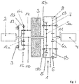
- a further exemplary embodiment of a drive arrangement according to the invention is shown 3 . while in 1 and 2 the ring gear 12c of the auxiliary gear stage 12 is permanently connected to the housing 9 in a manner fixed to the housing, is in 3 provided that the switching element 13 is connected between the housing 9 and the ring gear 12c of the auxiliary gear stage 12 .
- the sun gear 12a of the auxiliary gear stage 12 is permanently non-rotatably connected to the shaft 10 and the electric machine 3 permanently rotatably coupled to the planetary carrier 14 of the auxiliary gear stage 12.
- the speeds of the components of the auxiliary planetary gear set 12 assume speeds that are determined by those of the two drive units 2, 3.
- the ring gear 12c of the auxiliary gear stage 12 is coupled to the housing 9 in order to restrict a degree of freedom of the differential gear 1 and to use the second drive assembly 3 to run up the first drive unit 2, with the load then being transferred via the auxiliary gear stage 12, starting from the second drive unit 3 in the direction of the first drive unit 2 is transmitted.
- the exemplary embodiments Figures 1 to 3 have in common that an element of the auxiliary gear stage 12 is either permanently (see 1 , 3 ) or switchable (see 2 ) is coupled to the second drive unit 3.
- auxiliary gear stage 12 it is also possible for the auxiliary gear stage 12 to interact with the shaft 11 on which the working machine 4 engages, either in such a way that an element of the auxiliary gear stage 12 is either permanently non-rotatably coupled to the shaft 11 or is coupled in a switchable manner is.
- the second drive unit 3 can be shifted together with the auxiliary gear stage to the other side of the differential gear 1 on which the shaft 11 runs.
- the second drive unit 3 and the auxiliary gear stage 12 can also be arranged on different sides of the differential gear 1 .
- the invention allows the drive arrangement to be run up via the second drive unit 3, specifically until the first drive unit 2 has reached its rated speed. So only the second drive unit 3 requires a converter. A starting aid on the first drive unit 2 is not required. If the switching element 13 closes automatically, a safety-relevant control device for activating the switching element 13 can be dispensed with.
- the invention also relates to a method for operating the drive arrangement according to the invention.
- the switching element 13 is closed, preferably automatically, in which case the still de-energized, first drive unit 2 is then run up to its nominal speed via the second drive unit 3 with the switching element 13 closed, and the auxiliary gear stage 12 speed in the direction of the first drive unit 2 transmits.
- the rated speed of the first drive unit 2 is reached, first the first drive unit 1 is energized and then the switching element 13 is opened. The speed of the second drive unit 3 is reduced and the switching element 13 is opened, preferably automatically.
Landscapes
- Engineering & Computer Science (AREA)
- General Engineering & Computer Science (AREA)
- Mechanical Engineering (AREA)
- Chemical & Material Sciences (AREA)
- Combustion & Propulsion (AREA)
- Transportation (AREA)
- Structure Of Transmissions (AREA)
- Retarders (AREA)
- Harvester Elements (AREA)
- Transmission Devices (AREA)
Abstract
Description
- Die Erfindung betrifft eine Antriebsanordnung einer Arbeitsmaschine zum Antreiben der Arbeitsmaschine mit variabel einstellbarer Drehzahl. Des Weiteren betrifft die Erfindung ein Verfahren zum Betreiben der Antriebsanordnung.
- Aus der Praxis sind Anwendungen bekannt, in welchen eine Arbeitsmaschine, wie zum Beispiel ein Verdichter oder eine Pumpe, mit einer variabel einstellbaren Drehzahl betrieben werden müssen. Hierfür werden nach der Praxis entweder als Antriebsaggregate Elektromotoren mit Frequenzumrichter eingesetzt, oder es kommt ein Getriebe mit einem hydraulisch oder elektrisch angetriebenen Überlagerungszweig zum Einsatz, mit welchem eine im benötigten Bereich variable Übersetzung bereitgestellt werden kann. Beide aus der Praxis bekannten Möglichkeiten zum Antreiben einer Arbeitsmaschine mit variabel einstellbarer Drehzahl sind aufwendig und teuer, wegen der für die Antriebsaufgabe benötigten hohen Leistungen sind Mittelspannung-Frequenzumrichter notwendig.
-
DE 10 2015 006 084 A1 offenbart eine Antriebsanordnung einer Arbeitsmaschine zum Antreiben der Arbeitsmaschine mit einer variabel einstellbaren Drehzahl, wobei die Antriebsanordnung neben der Arbeitsmaschine ein Differentialgetriebe und zwei Antriebsaggregate umfasst. Ein erstes Antriebsaggregat ist an ein erstes Element des Differentialgetriebes gekoppelt. Die Arbeitsmaschine ist an ein zweites Element des Differentialgetriebes gekoppelt. An ein drittes Element des Differentialgetriebes ist ein zweites Antriebsaggregat gekoppelt, dessen Drehzahl eine von der Drehzahl des ersten Antriebsaggregats abhängigen Drehzahl überlagerbar ist. Das erste Antriebsaggregat oder das zweite Antriebsaggregat sind mit einer variabel einstellbaren Drehzahl antreibbar. Diese Antriebsanordnung erlaubt es mit einfachen und kostengünstigen Mitteln eine Arbeitmaschine mit variabel einstellbarer Drehzahl anzutreiben. - Es besteht Bedarf daran, eine Antriebsanordnung einer mit einer variabel einstellbaren Drehzahl anzutreibenden Arbeitsmaschine zu schaffen, vorzugsweise eine Antriebsanordnung, bei welcher die Antriebsanordnung einfach und sicher auf eine Nenndrehzahl hochgefahren werden kann. Vorzugsweise soll vermieden werden, dass beim Verbinden eines nicht-drehzahlregelbaren Antriebsaggregats mit dem Stromnetz ein zu hoher Einschaltstrom verursacht wird, der entweder zu Netzstörungen oder zur Überhitzung beim Hochlauf führen kann.
- Hiervon ausgehend liegt der vorliegenden Erfindung die Aufgabe zugrunde, eine neuartiges Antriebsanordnung und ein Verfahren zum Betreiben der Antriebsanordnung schaffen. Diese Aufgabe wird durch eine Antriebsanordnung einer mit einer variabel einstellbaren Drehzahl anzutreibenden Arbeitsmaschine nach Anspruch 1 gelöst. Das Verfahren zum Betreiben der Antriebsanordnung ist in Anspruch 17 definiert.
- Die Antriebsanordnung weist ein Differentialgetriebe, ein an einem ersten Element des Differentialgetriebes gekoppeltes ersten Antriebsaggregat, eine an ein zweites Element des Differentialgetriebes gekoppelte Arbeitsmaschine, und ein an ein drittes Element des Differentialgetriebes gekoppeltes zweiten Antriebsaggregat auf, dessen Drehzahl einer von der Drehzahl des ersten Antriebsaggregat abhängigen Drehzahl überlagerbar ist. Das erste Antriebsaggregat oder das zweite Antriebsaggregat sind mit variabel einstellbarer Drehzahl antreibbar.
- Die Antriebsanordnung weist ferner eine Hilfs-Getriebestufe und ein mit der Hilfs-Getriebestufe zusammenwirkendes Schaltelement auf, wobei bei geschlossenem Schaltelement die Hilfs-Getriebestufe lastübertragend ist und die Drehzahlen von erstem Antriebsaggregat und zweitem Antriebsaggregat abhängig von zumindest einer Übersetzung der Hilfs-Getriebestufe gekoppelt sind, und wobei bei geöffnetem Schaltelement die Hilfs-Getriebestufe lastfrei ist und die Drehzahlen von erstem Antriebsaggregat und zweitem Antriebsaggregat entkoppelt. Über die Hilfs-Getriebestufe kann die Antriebsanordnung vorteilhafterweise einfach und zuverlässig unter Nutzung der Drehzahl-Variabilität des zweiten Antriebsaggregates auf Nenndrehzahl hochgefahren werden.
- Vorzugsweise ist das Schaltelement ein selbststätig schaltendes, nämlich selbststätig schließendes und selbsttätig öffnendes, Schaltelement wie ein Freilauf oder eine Synchronkupplung. So kann dann, wenn das erste Antriebsaggregat beim Hochfahren auf Nenndrehzahl gebracht wird, und dann, wenn die Drehzahl des zweiten Antriebsaggregats eine sicherheitsrelevante Überdrehzahl erreicht, das Schaltelement selbsttätig schließen und einen sicherheitskritischen Ausfall der Antriebsanordnung vermeiden. Ist die Drehzahl des ersten Antriebsaggregats größer als die Drehzahl des zweiten Antriebsaggregats, so öffnet das Schaltelement selbsttätig. Wird bei Ausfall einer Kontrolleinrichtung des zweiten Antriebsaggregates dessen Drehzahl unter Berücksichtigung der Übersetzung des Hilfs-Getriebestufe höher als die des ersten Antriebsaggregats, so schließt das Schaltelement selbsttätig. Durch Verwendung eines selbststätig schaltenden Schaltelements kann auf eine Steuerungseinheit verzichtet werden und ein sicherheitskritischer Schutz durch Nutzung mechanischer Komponenten einfach und zuverlässig gewährleistet werden.
- Alternativ kann das Schaltelement auch ein aktiv schaltendes Schaltelement wie eine Lamellenkupplung sein.
- Die Hilfs-Getriebestufe kann als Hilfs-Planetenradsatz ausgebildet sein. Die ist konstruktiv einfach und bevorzugt.
- Das Schaltelement koppelt in einer Ausführung in geschlossenem Zustand entweder das zweite Antriebsaggregat drehfest mit einem Element der Hilfs-Getriebestufe oder ein anderes Element des Hilfs-Getriebestufe drehfest an das erste Element oder das zweite Element des Differentialgetriebes.
- Wenn das Schaltelement geschlossen ist, sind kann das Differentialgetriebe nicht mehr als solches betrieben werden, das Differentialgetriebe hat dann eine feste Übersetzung.
- Vorzugsweise koppelt das Schaltelement in geschlossenem Zustand das zweite Antriebsaggregat drehfest mit einem Element der Hilfs-Getriebestufe, wobei ein anderes Element der Hilfs-Getriebestufe zusammen mit dem ersten Antriebsaggregat permanent drehfest an das erste Element des Differentialgetriebes gekoppelt ist.
- In einer anderen bevorzugten Ausführungsform ist vorgesehen, dass das zweite Antriebsaggregat permanent drehfest mit einem Element der Hilfs-Getriebestufe koppelt ist, wobei das Schaltelement in geschlossenem Zustand ein anderes Element der Hilfs-Getriebestufe drehfest an das erste Element des Differentialgetriebes koppelt.
- Diese beiden vorteilhaften Ausführungsformen der Erfindung sind besonders bevorzugt. Bei geschlossenem Schaltelement ist die Drehzahl des mithilfe des zweiten Antriebsaggregats auf Nenndrehzahl hochzufahrenden ersten Antriebsaggregats neben der Drehzahl des zweiten Antriebsaggregats ausschließlich von der Übersetzung der HilfsGetriebestufe abhängig.
- Die Übersetzung der Hilfs-Getriebestufe ist dabei vorzugsweise so gewählt, dass bei Maximaldrehzahl des zweiten Antriebsaggregats das erste Antriebsaggregat seine Nenndrehzahl erreicht.
- Bevorzugte Weiterbildungen der Erfindung ergeben sich aus den Unteransprüchen und der nachfolgenden Beschreibung. Ausführungsbeispiele der Erfindung werden, ohne hierauf beschränkt zu sein, an Hand der Zeichnung näher erläutert. Dabei zeigt:
- Fig. 1:
- ein Blockschaltbild einer ersten erfindungsgemäßen Antriebsanordnung;
- Fig. 2:
- ein Blockschaltbild einer zweiten erfindungsgemäßen Antriebsanordnung;
- Fig. 3:
- ein Blockschaltbild einer dritten erfindungsgemäßen Antriebsanordnung.
- Die Erfindung betrifft eine Antriebsanordnung einer mit einer variabel einstellbaren Drehzahl anzutreibenden Arbeitsmaschine, wobei es sich bei der Arbeitsmaschine zum Beispiel um einen Verdichter oder eine Pumpe handeln kann.
-
Fig. 1 zeigt ein erstes bevorzugtes Ausführungsbeispiel einer solchen Antriebsanordnung mit einem Differentialgetriebe 1, einem ersten Antriebsaggregat 2, einem zweiten Antriebsaggregat 3 und einer Arbeitsmaschine 4. Das erste Antriebsaggregat 2 wird auch als Hauptantriebsaggregat und das zweite Antriebsaggregat 3 auch als Überlagerungsantriebsaggregat bezeichnet. Bei diesen Antriebsaggregaten 2, 3 handelt es sich jeweils vorzugsweise um elektrische Maschinen. Das Differentialgetriebe 1 verfügt im gezeigten, bevorzugten Ausführungsbeispiel über einen ersten Planetenradsatz 5 mit einem Sonnenrad 5a und mindestens zwei Planetenrädern 5b, wobei die Planetenräder 5b in das Sonnenrad 5a des ersten Planetenradsatzes 5 kämmen. Das Differentialgetriebe 1 verfügt weiterhin über einen zweiten Planetenradsatz 6 mit einem Sonnenrad 6a und mindestens zwei Planetenrädern 6b, wobei die Planetenräder 6b in das Sonnenrad 6a kämmen. Jeweils zwei Planetenräder 5b, 6b der beiden Planetenradsätze 5, 6 sind an einer jeweiligen gemeinsamen Planetenwelle 7 angeordnet, sodass demnach jede der Planetenwellen 7 mit einem Planetenrad 5b des ersten Planetenradsatzes 5 und einem Planetenrad 6b des zweiten Planetenradsatzes 6 drehfest gekoppelt ist. Bei dem Differentialgetriebe 1 derFig. 1 sind die Planetenwellen 7 in einem Planetenträger 8 drehbar gelagert, wobei der Planetenträger 8 in einem im Detail nicht gezeigten, drehfesten Gehäuse 9 drehbar gelagert ist, vorzugsweise über nicht gezeigte Gleitlager. - Bei der erfindungsgemäßen Antriebsanordnung ist das erste Antriebsaggregat 2, welches als Hauptmotor bezeichnet wird, an ein erstes Element des Differentialgetriebes 1 gekoppelt, und zwar derart, dass das erste Antriebsaggregat 2 über eine Welle 10 permanent, direkt und drehfest mit dem ersten Element des Differentialgetriebes 1 gekoppelt ist, wobei es sich im Ausführungsbeispiel der
Fig. 1 bei diesem ersten Element des Differentialgetriebes 1, an welches das erste Antriebsaggregat 2 gekoppelt ist, um das Sonnenrad 5a des ersten Planetenradsatzes 5 handelt. - Es sei darauf hingewiesen, dass der erste Planetenradsatz 5 anstelle des Sonnenrads 5a auch ein Hohlrad aufweisen kann, wobei dann das erste Antriebsaggregat 2 über die Welle 10 an das Hohlrad des ersten Planetenradsatzes 5 gekoppelt ist, welches dann radial außen in die Planetenräder 5b kämmt.
- Die Arbeitsmaschine 4 ist an ein zweites Element des Differentialgetriebes 1 gekoppelt, und zwar gemäß
Fig. 1 derart, dass die Arbeitsmaschine 4 über eine Welle 11 permanent, direkt und drehfest an das Sonnenrad 6a des zweiten Planetenradsatzes 6 gekoppelt ist. - Das zweite Antriebsaggregat 3 greift an einem dritten Element des Differentialgetriebes 1 an, wobei es sich bei diesem dritten Element des Differentialgetriebes 1, an welchem das zweite Antriebsaggregat 3 angreift, im gezeigten Ausführungsbeispiel um den Planetenträger 8 des Differentialgetriebes 1 handelt. Der Antrieb des Planetenträgers 8 erfolgt demnach über das zweite Antriebsaggregat 3, dessen Drehzahl bzw. Antriebsleistung der Drehzahl bzw. Antriebsleistung des ersten Antriebsaggregats 2 überlagert wird. Dabei wird das erste Antriebsaggregat 2 vorzugsweise mit fester bzw. konstanter Drehzahl antrieben, wohingegen das zweite Antriebsaggregat 3 vorzugsweise mit variabler Drehzahl angetrieben wird. So kann dann, wenn das erste Antriebsaggregat 2 mit der konstanten Drehzahl läuft, ausgehend von dem zweiten Antriebsaggregat 3 der von der Drehzahl des ersten Antriebsaggregats 2 abhängigen Drehzahl eine Drehzahl stufenlos überlagert werden, um an der Arbeitsmaschine 4 eine variable Drehzahl einzustellen.
- Die erfindungsgemäße Antriebsanordnung verfügt zusätzlich zum Differentialgetriebe 1, den beiden Antriebsaggregaten 2, 3 und der Arbeitsmaschine 4 über eine Hilfs-Getriebestufe 12 sowie über ein mit der Hilfs-Getriebestufe 12 zusammenwirkendes Schaltelement 13. Dann, wenn das Schaltelement 13 geschlossen ist, ist die Hilfs-Getriebestufe 12 lastübertragend und die Drehzahlen von erstem Antriebsaggregat 2 und zweitem Antriebsaggregat 3 sind gekoppelt, und zwar abhängig von der Übersetzung der Hilfs-Getriebestufe 12.
- Dann, wenn das Schaltelement 13 geschlossen ist, stehen die Drehzahlen der beiden Antriebsaggregate 2 und 3 in einem festen Verhältnis. Auch die Arbeitsmaschine 4 nimmt dann eine Drehzahl an, die noch von der Drehzahl der Antriebsaggregate 2, 3 abhängt. Wird nur das zweite Antriebsaggregat 3 mit elektrischem Strom versorgt, so ist die Drehzahl des zweiten Antriebsaggregats 3 maßgebend für alle anderen Drehzahlen der Antriebsanordnung - das zweite Antriebsaggregat 3 treibt dann die Antriebsanordnung alleine an.
- Ist hingegen das Schaltelement 13 geöffnet, so ist die Hilfs-Getriebestufe 12 lastfrei und die Drehzahlen von erstem Antriebsaggregat 2 und zweitem Antriebsaggregat 3 sind entkoppelt. Das zweite Antriebsaggregat 3 stellt dann nur den Überlagerungsanteil von Leistung und Drehzahl bereit.
- Im geschlossenen Zustand wirkt das Schaltelement 13 demnach im Sinne einer Sperre für das Differentialgetriebe 1, um einen Freiheitsgrad des Differentialgetriebes 1 zu sperren. Dies wird insbesondere für das Hochfahren der Antriebsanordnung, ausgehend von einem stillstehenden, ersten Antriebsaggregat 2 genutzt, um so das erste Antriebsaggregat 2 ausgehend vom zweiten Antriebsaggregat 3 auf seine Nenndrehzahl zu bringen.
- Bei einem solchen Hochfahren des ersten Antriebsaggregats 2, ausgehend vom zweiten Antriebsaggregat 3 bei geschlossenem Schaltelement 13 ist das erste Antriebsaggregat 2 stromlos, erst nach Erreichen der Nenndrehzahl des ersten Antriebsaggregats 2 wird dann zunächst das erste Antriebsaggregat 2 bestromt und dann anschließend das Schaltelement 13 geöffnet.
- Die Hilfs-Getriebestufe 12 verfügt über ein Sonnenrad 12a, Planetenräder 12b und ein Hohlrad 12c. Die Planetenräder 12b sind auf einem Planetenträger 14 drehbar gelagert.
- In
Fig. 1 greift ein Element der Hilfs-Getriebestufe 12, nämlich das Sonnenrad 12a, zusammen mit dem ersten Antriebsaggregat 2 permanent, direkt und drehfest an der Welle 10 und so am ersten Element des Differentialgetriebes 1, inFig. 1 am Sonnenrad 5a des ersten Planetenradsatzes 5 des Differentialgetriebes 1, an. - Dann, wenn das Schaltelement 13 geschlossen ist, koppelt dasselbe in
Fig. 1 das zweite Antriebsaggregat 3 drehfest an ein zweites Element der Hilfs-Getriebestufe 12, und zwar inFig. 1 an den Planetenträger 14. - Im Ausführungsbeispiel der
Fig. 1 treibt demnach das erste Antriebsaggregat 2 über das Sonnenrad 5a und die Planetenwellen 7 das Sonnenrad 6a und über das Sonnenrad 6a die Arbeitsmaschine 4 an. Über den drehbar gelagerten Planetenträger 8 des Differentialgetriebes 1 kann im regulären Betrieb ausgehend von dem zweiten Antriebsaggregat 3 der von der Drehzahl des ersten Antriebsaggregats 2 abhängigen Drehzahl an der Welle 11 eine Drehzahl überlagert werden, um an der Arbeitsmaschine 4 eine variable Drehzahl einzustellen. - Im regulären Betrieb, nämlich dann, wenn das erste Antriebsaggregat 2 mit seiner Nenndrehzahl betrieben wird, ist das Schaltelement 13 geöffnet. Um jedoch die Antriebsanordnung hochzufahren, insbesondere ausgehend von einem Zustand, in welchem das erste Antriebsaggregat 2 stillsteht, wird das Schaltelement 13 geschlossen und das zweite Antriebsaggregat 3 über das Schaltelement 13 an die Hilfs-Getriebestufe 12 und an die Welle 10 gekoppelt bzw. drehfest angebunden. Hiermit wird ein Freiheitsgrad des Differentialgetriebes 1 gesperrt und das Hochfahren der Antriebsanordnung bis zur Nenndrehzahl des beim Hochfahren stromlosen ersten Antriebsaggregats 2 durch das zweite Antriebsaggregat 3 ermöglicht. Die Übersetzung der Hilfs-Getriebestufe 12 ist so gewählt, dass bei Maximaldrehzahl des zweiten Antriebsaggregats 3 das erste Antriebsaggregat 2 seine Nenndrehzahl erreicht.
- Bei dem Schaltelement 13 kann es sich um ein reibschlüssiges Schaltelement in Form einer Reibkupplung, wie zum Beispiel einer Lamellenkupplung oder auch um ein formschlüssiges Schaltelement in Form einer Klauenkupplung handeln. Dann, wenn das Schaltelement 13 als Reibkupplung ausgebildet ist, kann diese die Funktion einer Bremse für das zweite Antriebsaggregat 3 übernehmen, wenn dieses im Betrieb ausfallen sollte.
- Besonders bevorzugt ist eine Ausführung, in welcher das Schaltelement 13 als selbsttätig schließendes und selbsttätig öffnendes Schaltelement 13, insbesondere als Freilauf oder Synchronkupplung, ausgeführt ist, bei welchem Drehmoment ausschließlich in einer Drehrichtung übertragbar ist. Hierdurch kann erreicht werden, dass das Schaltelement 13 beim Hochfahren der Antriebsanordnung 1 selbsttätig schließt, ebenso bei einem sicherheitskritischen Ausfall des zweiten Antriebsaggregats 3 im Betrieb. Ist die Drehzahl des ersten Antriebsaggregats 2 größer als die Drehzahl des zweiten Antriebsaggregats 3, so öffnet das Schaltelement 13 selbsttätig und der reguläre Überlagerungsbetrieb kann beginnen.
- Sobald die Drehzahl des ersten Antriebsaggregats 2 seine Nenndrehzahl erreicht, welches angeschleppt durch das zweite Antriebsaggregat 3 beim Anschalten ohne Spannungsspitze bereits auf seiner Nenndrehzahl läuft, kann das Schaltelement 13 geöffnet werden.
- Das erfolgt bei einer vorzugsweise verwendeten selbstschaltenden Ausführung des Schaltelements 13 dadurch, dass die Drehzahl des zweiten Antriebsaggregates 3 - unter Berücksichtigung der Übersetzung der vorzugsweise als Hilfs-Planetenradsatz ausgebildeten Hilfs-Gertriebstufe12 - gegenüber der des ersten Antriebsaggregates 2 gesenkt wird, bei einer Schaltkupplung durch Öffnen der Kupplung. Die selbstschaltende Ausführung des Schaltelements 13 als Synchronkupplung oder Freilauf ist jedoch bevorzugt.
- Das Schaltelement 13 bleibt im gesamten Normalbetrieb, also dann, wenn das erste Antriebsaggregat 2 mit Nenndrehzahl läuft, geöffnet. Bei Verwendung eines selbstschaltenden Schaltelements 13 ist keine sicherheitsrelevante Steuereinheit erforderlich. Sicherheitskritische Funktionen können durch mechanische Komponenten bereitgestellt werden, nämlich durch das selbsttätig schließende Schaltelement 13. Für die Verblockung des Differentialgetriebes 1 ist kein Aktuator erforderlich. Die Verblockung des Differentialgetriebes 1 erfolgt selbsttätig. Auch für das Entblocken des Differentialgetriebes 1 ist kein Aktuator erforderlich. Dann, wenn die Drehzahl des ersten Antriebsaggregats 2 größer als die Drehzahl des zweiten Antriebsaggregats 3, ist das Schaltelement 13 selbsttätig geöffnet. Der Hilfs-Planetensatz 12 dreht immer mit der Drehzahl des ersten Antriebsaggregates 2.
-
Fig. 2 zeigt eine Abwandlung der erfindungsgemäßen Antriebsanordnung, bei welcher das zweite Antriebsaggregat 3 permanent und drehfest an ein Element der Hilfs-Getriebestufe 12 gekoppelt ist, nämlich an den Planetenträger 14. Über das Schaltelement 13 kann inFig. 2 das Sonnenrad 12a des Planetenradsatzes 12 drehfest an das erste Element des Differentialgetriebes 1, nämlich inFig. 2 an das Sonnenrad 5a des ersten Planetenradsatzes 5 des Differentialgetriebes 1, gekoppelt werden. InFig. 2 ist demnach das Schaltelement 13 zwischen das Sonnenrad 12a und die Welle 10 geschaltet. Der Hilfs-Planetensatz 12 dreht immer mit der Drehzahl des zweiten Antriebsaggregates 3. - Ein weiteres Ausführungsbeispiel einer erfindungsgemäßen Antriebsanordnung zeigt
Fig. 3 . Während inFig. 1 und2 das Hohlrad 12c der Hilfs-Getriebestufe 12 jeweils permanent gehäusefest an das Gehäuse 9 angebunden ist, ist inFig. 3 vorgesehen, dass das Schaltelement 13 zwischen das Gehäuse 9 und das Hohlrad 12c der Hilfs-Getriebestufe 12 geschaltet ist. InFig. 3 ist das Sonnenrad 12a der Hilfs-Getriebestufe 12 permanent drehfest an die Welle 10 und die elektrische Maschine 3 permanent drehfest an den Planetenträger 14 der Hilfs-Getriebestufe 12 gekoppelt. Die Drehzahlen der Komponenten des Hilfs-Planetensatzes 12 nehmen Drehzahlen an, die von denen der beiden Antriebsaggregate 2, 3 bestimmt sind. - Durch Schließen des Schaltelements 13 wird das Hohlrad 12c der Hilfs-Getriebestufe 12 an das Gehäuse 9 gekoppelt, um einen Freiheitsgrad des Differentialgetriebes 1 einzuschränken und zum Hochfahren des ersten Antriebsaggregats 2 das zweite Antriebsaggregat 3 zu nutzen, wobei hierzu dann Last über die Hilfs-Getriebestufe 12, ausgehend von dem zweiten Antriebsaggregat 3 in Richtung auf das erste Antriebsaggregat 2 übertragen wird.
- Den Ausführungsbeispielen der
Fig. 1 bis 3 ist gemeinsam, dass ein Element der Hilfs-Getriebestufe 12 entweder permanent (sieheFig. 1 ,3 ) oder schaltbar (sieheFig. 2 ) an das zweite Antriebsaggregat 3 gekoppelt ist. - Im Unterschied hierzu ist es auch möglich, dass die Hilfs-Getriebestufe 12 mit der Welle 11 zusammenwirkt, an welcher die Arbeitsmaschine 4 angreift, und zwar entweder derart, dass ein Element der Hilfs-Getriebestufe 12 entweder permanent drehfest oder schaltbar an die Welle 11 gekoppelt ist. Dabei kann das zweite Antriebsaggregat 3 zusammen mit der Hilfs-Getriebestufe auf die andere Seite Differentialgetriebes 1 verlagert sein, an welcher die Welle 11 verläuft. Das zweite Antriebsaggregat 3 und die Hilfs-Getriebestufe 12 könne auch auf unterschiedlichen Seiten des Differentialgetriebes 1 angeordnet sein.
- Die Erfindung erlaubt es, die Antriebsanordnung über das zweite Antriebsaggregat 3 hochzufahren, und zwar bis das erste Antriebsaggregat 2 seine Nenndrehzahl erreicht hat. So benötigt lediglich das zweite Antriebsaggregat 3 einen Umrichter. Eine Anfahrhilfe am ersten Antriebsaggregat 2 entfällt. Dann, wenn das Schaltelement 13 selbsttätig schließt, kann auf eine sicherheitsrelevante Steuerungseinrichtung zum Ansteuern des Schaltelements 13 verzichtet werden.
- Dies wird durch Nutzen vorzugsweise einer Synchronkupplung oder eines Freilaufs erreicht, die oder der zum Hochfahren der Antriebsanordnung selbsttätig schließt und selbsttätig öffnet.
- Die Erfindung betrifft weiterhin ein Verfahren zum Betreiben der erfindungsgemäßen Antriebsanordnung. Zum Starten derselben wird das Schaltelement 13 geschlossen, vorzugsweise selbsttätig, wobei dann das noch stromlose, erste Antriebsaggregat 2 über das zweite Antriebsaggregat 3 bei geschlossenem Schaltelement 13 bis zu seiner Nenndrehzahl hochgefahren wird und hierbei die Hilfs-Getriebestufe 12 Drehzahl in Richtung auf das erste Antriebsaggregat 2 überträgt. Mit Erreichen der Nenndrehzahl am ersten Antriebsaggregat 2 wird zunächst das erste Antriebsaggregat 1 bestromt und anschließend das Schaltelement 13 geöffnet. Die Drehzahl des zweiten Antriebsaggregats 3 wird reduziert und das das Schaltelement 13 wird geöffnet, vorzugsweise selbsttätig.
- Bei der Auslegung des zweiten Antriebsaggregats 3 sollte darauf geachtet werden, dass die Arbeitsmaschine 4 ein anwendungsspezifisches Hochlaufmoment entwickelt, das sich zu seiner Drehzahl in einer bekannten Funktion verhält. Dieses Drehmoment bzw. die erforderliche Leistung muss vom zweiten Antriebsaggregat 3 zwar nur kurzzeitig bis zum Bestromen des ersten Antriebsaggregates 2 aber zuverlässig bereitgestellt werden.
-
- 1
- Differentialgetriebe
- 2
- erstes Antriebsaggregat
- 3
- zweites Antriebsaggregat
- 4
- Arbeitsmaschine
- 5
- erster Planetenradsatz
- 5a
- Sonnenrad
- 5b
- Planetenrad
- 6
- zweiter Planetenradsatz
- 6a
- Sonnenrad
- 6b
- Planetenrad
- 7
- Planetenwelle
- 8
- Planetenträger
- 9
- Gehäuse
- 10
- Welle
- 11
- Welle
- 12
- Hilfs-Getriebestufe
- 12a
- Sonnenrad
- 12b
- Planetenrad
- 12c
- Hohlrad
- 13
- Schaltelement
- 14
- Planetenträger
Claims (17)
- Antriebsanordnung einer mit einer variabel einstellbaren Drehzahl anzutreibenden Arbeitsmaschine (4),mit einem Differentialgetriebe (1),mit einem an ein erstes Element des Differentialgetriebes (1) gekoppelten ersten Antriebsaggregat (2),mit einer an ein zweites Element des Differentialgetriebes (1) gekoppelten Arbeitsmaschine (4),mit einem an ein drittes Element des Differentialgetriebes (1) gekoppelten zweiten Antriebsaggregat (3), dessen Drehzahl einer von der Drehzahl des ersten Antriebsaggregats (2) abhängigen Drehzahl überlagerbar ist,wobei das erste Antriebsaggregat (2) oder das zweite Antriebsaggregat (2) mit variabel einstellbarer Drehzahl antreibbar sind,gekennzeichnet durcheine Hilfs-Getriebestufe (12) und ein mit der Hilfs-Getriebestufe (12) zusammenwirkendes Schaltelement (13),wobei bei geschlossenem Schaltelement (13) die Hilfs-Getriebestufe (12) lastübertragend ist und die Drehzahlen von erstem Antriebsaggregat (2) und zweitem Antriebsaggregat (3) abhängig von zumindest einer Übersetzung der HilfsGetriebestufe (12) gekoppelt sind, undwobei bei geöffnetem Schaltelement (13) die Hilfs-Getriebestufe (12) lastfrei ist und die Drehzahlen von erstem Antriebsaggregat (2) und zweitem Antriebsaggregat (3) entkoppelt sind.
- Antriebsanordnung nach Anspruch 1, dadurch gekennzeichnet, dass die Hilfs-Getriebestufe (12) als Hilfs-Planetenradsatz ausgebildet ist.
- Antriebsanordnung nach Anspruch 1 oder 2, dadurch gekennzeichnet, dass das Schaltelement (13) ein Freilauf oder eine Synchronkupplung ist.
- Antriebsanordnung nach einem der Ansprüche 1 bis 3, dadurch gekennzeichnet, dass das Schaltelement (13) selbststätig schaltet, also selbststätig schließt und selbststätig öffnet.
- Antriebsanordnung nach Anspruch 1 oder 2, dadurch gekennzeichnet, dass das Schaltelement (13) eine reibschlüssige Kupplung ist.
- Antriebsanordnung nach einem der Ansprüche 1 bis 5, dadurch gekennzeichnet, dass das Schaltelement (13) in geschlossenem Zustand entweder das zweite Antriebsaggregat (3) drehfest mit einem Element der Hilfs-Getriebestufe (12) oder ein anderes Element des Hilfs-Getriebestufe (12) drehfest an das erste Element oder das zweite Element des Differentialgetriebes (1) koppelt.
- Antriebsanordnung nach einem der Ansprüche 1 bis 6, dadurch gekennzeichnet, dassdas Schaltelement (13) in geschlossenem Zustand das zweite Antriebsaggregat (3) drehfest mit einem Element der Hilfs-Getriebestufe (12) koppelt,ein anderes Element der Hilfs-Getriebestufe (12) zusammen mit dem ersten Antriebsaggregat (2) permanent drehfest an das erste Element des Differentialgetriebes (1) gekoppelt ist.
- Antriebsanordnung nach einem der Ansprüche 1 bis 6, dadurch gekennzeichnet, dassdas Schaltelement (13) in geschlossenem Zustand das zweite Antriebsaggregat (3) drehfest mit einem Element der Hilfs-Getriebestufe (12) koppelt, wobeiein anderes Element der Hilfs-Getriebestufe (12) zusammen mit der Arbeitsmaschine (4) permanent drehfest an das zweite Element des Differentialgetriebes (1) gekoppelt ist.
- Antriebsanordnung nach einem der Ansprüche 1 bis 6, dadurch gekennzeichnet, dassdas zweite Antriebsaggregat (3) permanent drehfest mit einem Element der Hilfs-Getriebestufe (12) gekoppelt ist,das Schaltelement (13) in geschlossenem Zustand ein anderes Element der Hilfs-Getriebestufe (12) drehfest an das erste Element des Differentialgetriebes (1) koppelt.
- Antriebsanordnung nach einem der Ansprüche 1 bis 6, dadurch gekennzeichnet, dassdas zweite Antriebsaggregat (3) permanent drehfest mit einem Element der Hilfs-Getriebestufe (12) gekoppelt ist,das Schaltelement (13) in geschlossenem Zustand ein anderes Element der Hilfs-Getriebestufe (12) drehfest an das zweite Element des Differentialgetriebes (1) koppelt.
- Antriebsanordnung nach einem der Ansprüche 1 bis 6, dadurch gekennzeichnet, dassdas zweite Antriebsaggregat (3) permanent drehfest mit einem Element der Hilfs-Getriebestufe (12) gekoppelt ist,ein anderes Element der Hilfs-Getriebestufe (12) zusammen mit dem ersten Antriebsaggregat (2) permanent drehfest an das erste Element des Differentialgetriebes (1) gekoppelt ist,das Schaltelement (13) in geschlossenem Zustand ein anderes Element der Hilfs-Getriebestufe (12) an ein Gehäuse koppelt.
- Antriebsanordnung nach einem der Ansprüche 1 bis 6, dadurch gekennzeichnet, dassdas zweite Antriebsaggregat (3) permanent drehfest mit einem Element der Hilfs-Getriebestufe (12) gekoppelt ist,ein anderes Element der Hilfs-Getriebestufe (12) zusammen mit der Arbeitsmaschine (4) permanent drehfest an das zweite Element des Differentialgetriebes (1) gekoppelt ist,das Schaltelement (13) in geschlossenem Zustand ein anderes Element der Hilfs-Getriebestufe (12) an ein Gehäuse koppelt.
- Antriebsanordnung nach einem der Ansprüche 1 bis 12, dadurch gekennzeichnet, dassdas Differentialgetriebe (1) einen ersten Planetenradsatz (5) aufweist, an den das erste Antriebsaggregat (2) gekoppelt ist,das Differentialgetriebe (1) einen zweiten Planetenradsatz (6) aufweist, an den die Arbeitsmaschine (4) gekoppelt ist,der erste Planetenradsatz (5) und der zweite Planetenradsatz (6) jeweils Planetenräder (5b, 6b) aufweisen, die auf mindestens zwei gemeinsamen Planetenwellen (7), die in einem Planetenträger (8) gelagert sind, angeordnet sind;der Planetenträger (8) in einem Gehäuse (9) drehbar gelagert und von dem zweiten Antriebsaggregat (3) antreibbar ist.
- Antriebsanordnung nach Anspruch 13, dadurch gekennzeichnet, dassder erste Planetenradsatz (5) ein Sonnenrad (5a) aufweist, an welches das erste Antriebsaggregat (2) gekoppelt ist, wobei das Sonnenrad (5a) des ersten Planetenradsatzes (5) in die auf den Planetenwellen (7) angeordneten Planetenräder (5b) des ersten Planetenradsatzes (5) kämmt, oderder erste Planetenradsatz (5) ein Hohlrad aufweist, an welches das erste Antriebsaggregat (3) gekoppelt ist, wobei das Hohlrad des ersten Planetenradsatzes (5) in die auf den Planetenwellen (7) angeordneten Planetenräder (5b) des ersten Planetenradsatzes (5) kämmt.
- Antriebsanordnung nach Anspruch 13 oder 14, dadurch gekennzeichnet, dass
der zweite Planetenradsatz (6) ein Sonnenrad (6a) aufweist, an welches die Arbeitsmaschine (5) gekoppelt ist, wobei das Sonnenrad (6a) des zweiten Planetenradsatzes (6) in die auf den Planetenwellen (7) angeordneten Planetenräder (6b) des zweiten Planetenradsatzes (6) kämmt. - Antriebsanordnung nach einem der Ansprüche 1 bis 15, dadurch gekennzeichnet, dass das erste Antriebsaggregat (2) mit konstanter Drehzahl und das zweite Antriebsaggregat (3) mit variabler Drehzahl antreibbar ist.
- Verfahren zum Betreiben einer Antriebsanordnung nach einem der Ansprüche 1 bis 16, mit folgenden Schritten:zum Starten der Antriebsanordnung wird das Schaltelement (13) geschlossen und das noch stromlose, erste Antriebsaggregat (2) wird über das zweite Antriebsaggregat (3) bis zu seiner Nenndrehzahl hochgefahren,mit Erreichen der Nenndrehzahl am ersten Antriebsaggregat (2) wird das erste Antriebsaggregat (2) bestromt und das Schaltelement (13) geöffnet.
Applications Claiming Priority (1)
| Application Number | Priority Date | Filing Date | Title |
|---|---|---|---|
| DE102021206701.8A DE102021206701B3 (de) | 2021-06-28 | 2021-06-28 | Antriebsanordnung einer mit einer variabel einstellbaren Drehzahl anzutreibenden Arbeitsmaschine und Verfahren zum Betreiben der Antriebsanordnung |
Publications (3)
| Publication Number | Publication Date |
|---|---|
| EP4112973A1 true EP4112973A1 (de) | 2023-01-04 |
| EP4112973C0 EP4112973C0 (de) | 2025-10-08 |
| EP4112973B1 EP4112973B1 (de) | 2025-10-08 |
Family
ID=82321349
Family Applications (1)
| Application Number | Title | Priority Date | Filing Date |
|---|---|---|---|
| EP22181129.2A Active EP4112973B1 (de) | 2021-06-28 | 2022-06-27 | Antriebsanordnung einer mit einer variabel einstellbaren drehzahl anzutreibenden arbeitsmaschine und verfahren zum betreiben der antriebsanordnung |
Country Status (6)
| Country | Link |
|---|---|
| US (1) | US11852223B2 (de) |
| EP (1) | EP4112973B1 (de) |
| JP (1) | JP7509827B2 (de) |
| CN (1) | CN115596820A (de) |
| DE (1) | DE102021206701B3 (de) |
| ES (1) | ES3053670T3 (de) |
Citations (4)
| Publication number | Priority date | Publication date | Assignee | Title |
|---|---|---|---|---|
| DE102012219125A1 (de) * | 2012-10-19 | 2014-04-24 | Zf Friedrichshafen Ag | Planetengetriebe für einen Hybridantrieb eines Kraftfahrzeugs |
| WO2016172742A1 (de) * | 2015-04-27 | 2016-11-03 | Set Sustainable Energy Technologies Gmbh | Triebstrang für pumpen, energieerzeugungsanlagen oder dergleichen und verfahren zum anfahren eines solchen triebstranges |
| DE102015006084A1 (de) | 2015-05-09 | 2016-11-10 | Renk Aktiengesellschaft | Getriebe und Antriebsanordnung mit einem Getriebe |
| DE102015212736A1 (de) * | 2015-07-08 | 2017-01-12 | Schaeffler Technologies AG & Co. KG | Antriebsanordnung für ein Fahrzeug sowie Fahrzeug mit der Antriebsanordnung |
Family Cites Families (6)
| Publication number | Priority date | Publication date | Assignee | Title |
|---|---|---|---|---|
| JP5924140B2 (ja) | 2012-06-05 | 2016-05-25 | 日本精工株式会社 | 電気自動車用駆動装置 |
| AT514281A3 (de) * | 2013-05-17 | 2015-10-15 | Gerald Dipl Ing Hehenberger | Verfahren zum Betreiben eines Triebstranges und Triebstrang |
| WO2017216888A1 (ja) | 2016-06-15 | 2017-12-21 | 三菱重工コンプレッサ株式会社 | 可変速増速機及び可変速増速機の始動方法 |
| DE102016213639A1 (de) * | 2016-07-26 | 2018-02-01 | Voith Patent Gmbh | Antriebsvorrichtung und Verfahren zur Drehzahllimitierung |
| US10316946B2 (en) * | 2017-10-13 | 2019-06-11 | E-Aam Driveline Systems Ab | Two mode electric drive module with Ravigneaux gearset |
| DE102020215133A1 (de) * | 2020-12-01 | 2022-06-02 | Dana Belgium N.V. | Elektrischer antriebsstrang und verfahren zum betrieb eines elektrischen antriebsstrangs |
-
2021
- 2021-06-28 DE DE102021206701.8A patent/DE102021206701B3/de active Active
-
2022
- 2022-06-27 ES ES22181129T patent/ES3053670T3/es active Active
- 2022-06-27 EP EP22181129.2A patent/EP4112973B1/de active Active
- 2022-06-27 JP JP2022102593A patent/JP7509827B2/ja active Active
- 2022-06-28 CN CN202210738505.2A patent/CN115596820A/zh active Pending
- 2022-06-28 US US17/851,703 patent/US11852223B2/en active Active
Patent Citations (4)
| Publication number | Priority date | Publication date | Assignee | Title |
|---|---|---|---|---|
| DE102012219125A1 (de) * | 2012-10-19 | 2014-04-24 | Zf Friedrichshafen Ag | Planetengetriebe für einen Hybridantrieb eines Kraftfahrzeugs |
| WO2016172742A1 (de) * | 2015-04-27 | 2016-11-03 | Set Sustainable Energy Technologies Gmbh | Triebstrang für pumpen, energieerzeugungsanlagen oder dergleichen und verfahren zum anfahren eines solchen triebstranges |
| DE102015006084A1 (de) | 2015-05-09 | 2016-11-10 | Renk Aktiengesellschaft | Getriebe und Antriebsanordnung mit einem Getriebe |
| DE102015212736A1 (de) * | 2015-07-08 | 2017-01-12 | Schaeffler Technologies AG & Co. KG | Antriebsanordnung für ein Fahrzeug sowie Fahrzeug mit der Antriebsanordnung |
Also Published As
| Publication number | Publication date |
|---|---|
| EP4112973C0 (de) | 2025-10-08 |
| CN115596820A (zh) | 2023-01-13 |
| DE102021206701B3 (de) | 2022-09-01 |
| BR102022012765A2 (pt) | 2023-03-07 |
| EP4112973B1 (de) | 2025-10-08 |
| ES3053670T3 (en) | 2026-01-23 |
| US11852223B2 (en) | 2023-12-26 |
| JP2023007489A (ja) | 2023-01-18 |
| JP7509827B2 (ja) | 2024-07-02 |
| US20220412442A1 (en) | 2022-12-29 |
Similar Documents
| Publication | Publication Date | Title |
|---|---|---|
| DE102010001259B4 (de) | Getriebeölpumpe für ein Automatgetriebe | |
| AT517170B1 (de) | Verfahren zum Anfahren eines Triebstranges | |
| EP3574232B1 (de) | Getriebe, antriebsanordnung mit einem getriebe und verfahren zum betreiben der antriebsanordnung | |
| WO2020078640A1 (de) | Getriebe und antriebssystem eines kraftfahrzeugs | |
| WO2020078628A1 (de) | Getriebe und antriebssystem eines kraftfahrzeugs | |
| DE102016222440B3 (de) | Antriebsvorrichtung für ein Kraftfahrzeug | |
| WO2018010934A1 (de) | Getriebe für ein kraftfahrzeug, hybridantrieb und kraftfahrzeug | |
| EP1499513A1 (de) | Hybridantriebssystem mit hydrodynamischer kupplung, insbesondere fuer kraftfahrzeuge | |
| WO2019141561A1 (de) | Getriebe für ein kraftfahrzeug, kraftfahrzeugantriebsstrang und verfahren zu dessen betreiben | |
| EP3810449B1 (de) | Antriebseinheit für einen antriebsstrang eines elektrisch antreibbaren kraftfahrzeugs und antriebsanordnung | |
| DE102018116613A1 (de) | Überlagerungsgetriebe | |
| DE102017222711B4 (de) | Getriebe für ein Kraftfahrzeug | |
| DE102017222717B4 (de) | Getriebe für ein Kraftfahrzeug | |
| DE102021206701B3 (de) | Antriebsanordnung einer mit einer variabel einstellbaren Drehzahl anzutreibenden Arbeitsmaschine und Verfahren zum Betreiben der Antriebsanordnung | |
| WO2020048711A1 (de) | Getriebe für ein kraftfahrzeug, kraftfahrzeuganstriebsstrang und verfahren zum betreiben eines getriebes | |
| WO2019091685A1 (de) | Verfahren zum betreiben eines hybridantriebsstrangs | |
| DE102017222710B4 (de) | Getriebe für ein Kraftfahrzeug | |
| DE102017222723B4 (de) | Getriebe für ein Kraftfahrzeug | |
| DE10312391A1 (de) | Hybridantrieb für Fahrzeuge | |
| DE102014208795B4 (de) | Getriebevorrichtung mit wenigstens einer Getriebeeingangswelle, mindestens einer Getriebeausgangswelle und mehreren Planetenradsätzen | |
| DE102017222724B4 (de) | Getriebe für ein Kraftfahrzeug | |
| DE102018200295B4 (de) | Getriebe für ein Kraftfahrzeug | |
| DE102017222722B4 (de) | Getriebe für ein Kraftfahrzeug | |
| DE102017222709B4 (de) | Getriebe für ein Kraftfahrzeug | |
| DE102018200296A1 (de) | Getriebe für ein Kraftfahrzeug |
Legal Events
| Date | Code | Title | Description |
|---|---|---|---|
| PUAI | Public reference made under article 153(3) epc to a published international application that has entered the european phase |
Free format text: ORIGINAL CODE: 0009012 |
|
| STAA | Information on the status of an ep patent application or granted ep patent |
Free format text: STATUS: THE APPLICATION HAS BEEN PUBLISHED |
|
| AK | Designated contracting states |
Kind code of ref document: A1 Designated state(s): AL AT BE BG CH CY CZ DE DK EE ES FI FR GB GR HR HU IE IS IT LI LT LU LV MC MK MT NL NO PL PT RO RS SE SI SK SM TR |
|
| STAA | Information on the status of an ep patent application or granted ep patent |
Free format text: STATUS: REQUEST FOR EXAMINATION WAS MADE |
|
| 17P | Request for examination filed |
Effective date: 20230703 |
|
| RBV | Designated contracting states (corrected) |
Designated state(s): AL AT BE BG CH CY CZ DE DK EE ES FI FR GB GR HR HU IE IS IT LI LT LU LV MC MK MT NL NO PL PT RO RS SE SI SK SM TR |
|
| STAA | Information on the status of an ep patent application or granted ep patent |
Free format text: STATUS: EXAMINATION IS IN PROGRESS |
|
| 17Q | First examination report despatched |
Effective date: 20240722 |
|
| GRAP | Despatch of communication of intention to grant a patent |
Free format text: ORIGINAL CODE: EPIDOSNIGR1 |
|
| STAA | Information on the status of an ep patent application or granted ep patent |
Free format text: STATUS: GRANT OF PATENT IS INTENDED |
|
| INTG | Intention to grant announced |
Effective date: 20250508 |
|
| GRAS | Grant fee paid |
Free format text: ORIGINAL CODE: EPIDOSNIGR3 |
|
| GRAA | (expected) grant |
Free format text: ORIGINAL CODE: 0009210 |
|
| STAA | Information on the status of an ep patent application or granted ep patent |
Free format text: STATUS: THE PATENT HAS BEEN GRANTED |
|
| AK | Designated contracting states |
Kind code of ref document: B1 Designated state(s): AL AT BE BG CH CY CZ DE DK EE ES FI FR GB GR HR HU IE IS IT LI LT LU LV MC MK MT NL NO PL PT RO RS SE SI SK SM TR |
|
| REG | Reference to a national code |
Ref country code: GB Ref legal event code: FG4D Free format text: NOT ENGLISH Ref country code: CH Ref legal event code: F10 Free format text: ST27 STATUS EVENT CODE: U-0-0-F10-F00 (AS PROVIDED BY THE NATIONAL OFFICE) Effective date: 20251008 |
|
| REG | Reference to a national code |
Ref country code: DE Ref legal event code: R096 Ref document number: 502022005684 Country of ref document: DE |
|
| REG | Reference to a national code |
Ref country code: IE Ref legal event code: FG4D Free format text: LANGUAGE OF EP DOCUMENT: GERMAN |
|
| U01 | Request for unitary effect filed |
Effective date: 20251107 |
|
| U07 | Unitary effect registered |
Designated state(s): AT BE BG DE DK EE FI FR IT LT LU LV MT NL PT RO SE SI Effective date: 20251117 |
|
| REG | Reference to a national code |
Ref country code: ES Ref legal event code: FG2A Ref document number: 3053670 Country of ref document: ES Kind code of ref document: T3 Effective date: 20260123 |
|
| PG25 | Lapsed in a contracting state [announced via postgrant information from national office to epo] |
Ref country code: HR Free format text: LAPSE BECAUSE OF FAILURE TO SUBMIT A TRANSLATION OF THE DESCRIPTION OR TO PAY THE FEE WITHIN THE PRESCRIBED TIME-LIMIT Effective date: 20251008 |
|
| PG25 | Lapsed in a contracting state [announced via postgrant information from national office to epo] |
Ref country code: RS Free format text: LAPSE BECAUSE OF FAILURE TO SUBMIT A TRANSLATION OF THE DESCRIPTION OR TO PAY THE FEE WITHIN THE PRESCRIBED TIME-LIMIT Effective date: 20260108 |
|
| PG25 | Lapsed in a contracting state [announced via postgrant information from national office to epo] |
Ref country code: IS Free format text: LAPSE BECAUSE OF FAILURE TO SUBMIT A TRANSLATION OF THE DESCRIPTION OR TO PAY THE FEE WITHIN THE PRESCRIBED TIME-LIMIT Effective date: 20260208 |
|
| PG25 | Lapsed in a contracting state [announced via postgrant information from national office to epo] |
Ref country code: PL Free format text: LAPSE BECAUSE OF FAILURE TO SUBMIT A TRANSLATION OF THE DESCRIPTION OR TO PAY THE FEE WITHIN THE PRESCRIBED TIME-LIMIT Effective date: 20251008 |