EP4112838A1 - Construction profile for dry construction of walls, partition walls, suspended ceilings and for fixing sanitary devices - Google Patents
Construction profile for dry construction of walls, partition walls, suspended ceilings and for fixing sanitary devices Download PDFInfo
- Publication number
- EP4112838A1 EP4112838A1 EP22181273.8A EP22181273A EP4112838A1 EP 4112838 A1 EP4112838 A1 EP 4112838A1 EP 22181273 A EP22181273 A EP 22181273A EP 4112838 A1 EP4112838 A1 EP 4112838A1
- Authority
- EP
- European Patent Office
- Prior art keywords
- construction profile
- longitudinal
- construction
- embossed
- walls
- Prior art date
- Legal status (The legal status is an assumption and is not a legal conclusion. Google has not performed a legal analysis and makes no representation as to the accuracy of the status listed.)
- Granted
Links
Images

Classifications
-
- E—FIXED CONSTRUCTIONS
- E04—BUILDING
- E04C—STRUCTURAL ELEMENTS; BUILDING MATERIALS
- E04C3/00—Structural elongated elements designed for load-supporting
- E04C3/02—Joists; Girders, trusses, or trusslike structures, e.g. prefabricated; Lintels; Transoms; Braces
- E04C3/04—Joists; Girders, trusses, or trusslike structures, e.g. prefabricated; Lintels; Transoms; Braces of metal
- E04C3/06—Joists; Girders, trusses, or trusslike structures, e.g. prefabricated; Lintels; Transoms; Braces of metal with substantially solid, i.e. unapertured, web
- E04C3/07—Joists; Girders, trusses, or trusslike structures, e.g. prefabricated; Lintels; Transoms; Braces of metal with substantially solid, i.e. unapertured, web at least partly of bent or otherwise deformed strip- or sheet-like material
-
- E—FIXED CONSTRUCTIONS
- E04—BUILDING
- E04B—GENERAL BUILDING CONSTRUCTIONS; WALLS, e.g. PARTITIONS; ROOFS; FLOORS; CEILINGS; INSULATION OR OTHER PROTECTION OF BUILDINGS
- E04B1/00—Constructions in general; Structures which are not restricted either to walls, e.g. partitions, or floors or ceilings or roofs
- E04B1/18—Structures comprising elongated load-supporting parts, e.g. columns, girders, skeletons
- E04B1/24—Structures comprising elongated load-supporting parts, e.g. columns, girders, skeletons the supporting parts consisting of metal
- E04B1/2403—Connection details of the elongated load-supporting parts
-
- E—FIXED CONSTRUCTIONS
- E04—BUILDING
- E04C—STRUCTURAL ELEMENTS; BUILDING MATERIALS
- E04C3/00—Structural elongated elements designed for load-supporting
- E04C3/02—Joists; Girders, trusses, or trusslike structures, e.g. prefabricated; Lintels; Transoms; Braces
- E04C3/04—Joists; Girders, trusses, or trusslike structures, e.g. prefabricated; Lintels; Transoms; Braces of metal
- E04C2003/0404—Joists; Girders, trusses, or trusslike structures, e.g. prefabricated; Lintels; Transoms; Braces of metal beams, girders, or joists characterised by cross-sectional aspects
- E04C2003/0408—Joists; Girders, trusses, or trusslike structures, e.g. prefabricated; Lintels; Transoms; Braces of metal beams, girders, or joists characterised by cross-sectional aspects characterised by assembly or the cross-section
- E04C2003/0421—Joists; Girders, trusses, or trusslike structures, e.g. prefabricated; Lintels; Transoms; Braces of metal beams, girders, or joists characterised by cross-sectional aspects characterised by assembly or the cross-section comprising one single unitary part
-
- E—FIXED CONSTRUCTIONS
- E04—BUILDING
- E04C—STRUCTURAL ELEMENTS; BUILDING MATERIALS
- E04C3/00—Structural elongated elements designed for load-supporting
- E04C3/02—Joists; Girders, trusses, or trusslike structures, e.g. prefabricated; Lintels; Transoms; Braces
- E04C3/04—Joists; Girders, trusses, or trusslike structures, e.g. prefabricated; Lintels; Transoms; Braces of metal
- E04C2003/0404—Joists; Girders, trusses, or trusslike structures, e.g. prefabricated; Lintels; Transoms; Braces of metal beams, girders, or joists characterised by cross-sectional aspects
- E04C2003/0426—Joists; Girders, trusses, or trusslike structures, e.g. prefabricated; Lintels; Transoms; Braces of metal beams, girders, or joists characterised by cross-sectional aspects characterised by material distribution in cross section
- E04C2003/043—Joists; Girders, trusses, or trusslike structures, e.g. prefabricated; Lintels; Transoms; Braces of metal beams, girders, or joists characterised by cross-sectional aspects characterised by material distribution in cross section the hollow cross-section comprising at least one enclosed cavity
-
- E—FIXED CONSTRUCTIONS
- E04—BUILDING
- E04C—STRUCTURAL ELEMENTS; BUILDING MATERIALS
- E04C3/00—Structural elongated elements designed for load-supporting
- E04C3/02—Joists; Girders, trusses, or trusslike structures, e.g. prefabricated; Lintels; Transoms; Braces
- E04C3/04—Joists; Girders, trusses, or trusslike structures, e.g. prefabricated; Lintels; Transoms; Braces of metal
- E04C2003/0404—Joists; Girders, trusses, or trusslike structures, e.g. prefabricated; Lintels; Transoms; Braces of metal beams, girders, or joists characterised by cross-sectional aspects
- E04C2003/0443—Joists; Girders, trusses, or trusslike structures, e.g. prefabricated; Lintels; Transoms; Braces of metal beams, girders, or joists characterised by cross-sectional aspects characterised by substantial shape of the cross-section
- E04C2003/0465—Joists; Girders, trusses, or trusslike structures, e.g. prefabricated; Lintels; Transoms; Braces of metal beams, girders, or joists characterised by cross-sectional aspects characterised by substantial shape of the cross-section square- or rectangular-shaped
Definitions
- the present invention relates to a construction profile for dry construction of walls, partition walls, suspended ceilings and for fixing sanitary appliances, which comprises a hollow longitudinal body from shaped sheet metal with connected edges of the sheet metal, which comprises a dovetail projection on each of its lateral sides, defined by longitudinal mounting embossed depressions located at the corners of the forming four-sided shape of the construction profile.
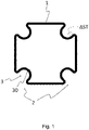
- FIG. 1 An exemplary embodiment of the construction profile according to background art is shown in Fig. 1 , showing a cross-section through a known construction profile, which has a square basic cross-section, wherein it is formed from sheet metal 1 and provided at the corners 2 with longitudinal mounting embossed depressions 3 with a bottom 30 having a semi-circular cross-section or having the shape of a longitudinally divided cylinder half.
- the object of the invention is to eliminate or at least reduce at least some of the disadvantages of the background art.
- the object of the invention is achieved by a construction profile for dry construction of walls, partition walls, suspended ceilings and for fixing sanitary appliances, whose principle consists in that the edges of the sheet metal are connected by a longitudinal pressed closure.
- Fig. 1 shows a cross-section through the construction profile known from the background art
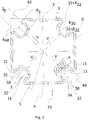
- Fig. 2 shows a cross-section through the construction profile according to the present invention
- Fig. 3 shows a spatial view of the construction profile according to the invention.
- the invention will be described with reference to an exemplary embodiment of a construction profile for dry construction of walls, partition walls, suspended ceilings and for fixing sanitary appliances.
- the construction profile is formed by a spatial body from shaped sheet metal 1.
- the construction profile has a substantially square basic cross-section, as shown in Fig. 2 by means of corners 10 of the forming four-sided shape, which is here, for example, a square, indicated in Fig. 2 by a dashed line.
- the longitudinal mounting embossed depressions 3 have a rounded bottom 30 and a pair of mutually opposing plane walls 31 .
- the plane walls 31 connect to the rounded bottom 30 with a transition arc 32 .
- the radius R 32 of the transition arcs 32 is 3 times to 8 times smaller than the radius R 30 of the rounded bottom 30 .
- the depth H 3 of the longitudinal mounting embossed depressions 3 is only by 10 to 20 % smaller than the width S 3 of the longitudinal mounting embossed depressions 3 .
- the length ⁇ AP of the plane walls 31 in the V direction from the circumference O of the construction profile to the centre S of the construction profile is 40 to 70 % of the depth H 3 of the longitudinal mounting embossed depressions 3 .
- the construction profile further comprises lateral sides 33 defined by the longitudinal mounting embossed depressions 3 , whereby these lateral sides 33 of the construction profile together with adjacent plane walls 31 of the longitudinal mounting embossed depressions 3 form a dovetail projection 34 , which widens in the direction from the centre S of the construction profile to the outer edge of the construction profile.
- the lateral sides 33 of the construction profile are provided with longitudinal auxiliary embossed depressions 5 , which can advantageously be created already within the rolling process of the construction profile from a strip of sheet metal 1 , e.g., galvanized steel sheet, or another suitable material.
- the longitudinal auxiliary embossed depressions 5 have a rounded cross-sectional shape and have a depth of half the thickness of the wall of the construction profile.
- the bottom 30 of one longitudinal mounting embossed depression 3 is formed by folding and pressing the edges 11 of the sheet 1 together, thereby joining the edges 11 of the sheet metal 1 together, to form a longitudinal pressed closure 4 which closes the construction profile without welding or otherwise joining the sheet 1 .
- the mutual folding and pressing of the edges 11 of the sheet metal 1 is at least double.
- the longitudinal pressed closure 4 is provided with a row of embossed spot depressions 40 arranged one behind the other, in the exemplary embodiment shown, situated along the entire length of the longitudinal pressed closure 4 .
- the embossed spot depressions 4 0 have substantially a conical shape and their longitudinal axis is perpendicular to the outer surface of the longitudinal pressed closure 4 , i.e., it is directed towards the centre S of the construction profile.
- the embossed spot depressions 40 are distributed along the length of the longitudinal pressed closure 4 at mutual intervals ⁇ 40 , for example here in the range from 5 mm to 25 mm.
- the longitudinal pressed closure 4 with optional embossed spot depressions 40 is situated in another part of the circumference O of the construction profile, e.g., in the surface of one lateral side 33 of the construction profile etc. Also in this embodiment, the longitudinal pressed closure 4 with optional embossed spot depressions 40 is preferably formed by at least double mutual folding and pressing of the edges 11 of the sheet metal 1 .
- the construction profile is produced in a required length, wherein if smaller lengths are required, the construction profile can be cut with the usual tools, e.g., by means of a hand-held or electrical saw, etc.
- the present invention is applicable in construction production for dry construction of walls, partition walls, suspended ceilings and for fixing sanitary appliances, such as WC modules, wash basins, bidets, urinals and other sanitary appliances.
Landscapes
- Engineering & Computer Science (AREA)
- Architecture (AREA)
- Civil Engineering (AREA)
- Structural Engineering (AREA)
- Physics & Mathematics (AREA)
- Electromagnetism (AREA)
- Rod-Shaped Construction Members (AREA)
- Finishing Walls (AREA)
Abstract
Description
- The present invention relates to a construction profile for dry construction of walls, partition walls, suspended ceilings and for fixing sanitary appliances, which comprises a hollow longitudinal body from shaped sheet metal with connected edges of the sheet metal, which comprises a dovetail projection on each of its lateral sides, defined by longitudinal mounting embossed depressions located at the corners of the forming four-sided shape of the construction profile.
- Systems for dry construction of walls, partition walls, suspended ceilings and for fixing sanitary appliances ceilings are available on the market from many manufacturers. These dry construction systems are also used for the construction of walls and partitions intended for fixing sanitary appliances, such as toilet modules, installation frames for wash basins, bidets, urinals and other sanitary appliances.
- An important component for these construction systems are longitudinal metal construction profiles, usually produced by successive rolling of galvanized sheet metal followed by longitudinal welding. These construction profiles are usually approximately square in cross-section and are provided with longitudinal mounting grooves of various shapes at the corners. Connecting elements, such as corner couplings, mounting feet, etc., are accordingly adapted to the shape and size of these grooves.
- An exemplary embodiment of the construction profile according to background art is shown in
Fig. 1 , showing a cross-section through a known construction profile, which has a square basic cross-section, wherein it is formed fromsheet metal 1 and provided at thecorners 2 with longitudinal mounting embosseddepressions 3 with abottom 30 having a semi-circular cross-section or having the shape of a longitudinally divided cylinder half. - The disadvantages of known construction profiles consist in the necessity of longitudinal welding of the sheet metal forming the construction profile, which results in increasing the negative impact on the environment, requires air filtration, produces toxic fumes, consumes a lot of energy and generates a large amount of heat, which additionally negatively affects the material characteristics of the sheet metal constituting the construction profile. As a result of the welding, it is also necessary to subsequently clean the weld area and to ensure the protection of the weld area against corrosion, which further increases the economic and environmental burden arising from the production of known construction profiles. Another drawback of the background art is also the presence of only a short section ΔST (see
Fig. 1 - background art) on the front part of the side walls of the individual embossed corner longitudinal mounting depressions. For certain applications, it also appears that it would be necessary for the construction profile to exhibit higher torsional rigidity and better resistance to buckling. - The object of the invention is to eliminate or at least reduce at least some of the disadvantages of the background art.
- The object of the invention is achieved by a construction profile for dry construction of walls, partition walls, suspended ceilings and for fixing sanitary appliances, whose principle consists in that the edges of the sheet metal are connected by a longitudinal pressed closure.
- The advantage of this solution is only the use of mechanical methods of production without the use of welding and other similar methods of joining sheets, thereby reducing the ecological burden and energy consumption of the production. In addition, it is not necessary to solve the problem of protecting the sheet metal edges from corrosion. Moreover, the use of a longitudinal pressed closure creates an additional strengthening element that improves the resistance of the construction profile in torsion and buckling. In combination with the features of preferred embodiments which are the subject of the dependent patent claims, a further improvement of not only in the form strength of the construction profile is achieved, but also in the increase of the clamping areas on the dovetail projections for fastening couplings, support feet, etc., thereby improving the usability of systems for dry construction.
- The invention is schematically represented in a drawing, wherein
Fig. 1 shows a cross-section through the construction profile known from the background art,Fig. 2 shows a cross-section through the construction profile according to the present invention andFig. 3 shows a spatial view of the construction profile according to the invention. - The invention will be described with reference to an exemplary embodiment of a construction profile for dry construction of walls, partition walls, suspended ceilings and for fixing sanitary appliances.
- The construction profile is formed by a spatial body from
shaped sheet metal 1. The construction profile has a substantially square basic cross-section, as shown inFig. 2 by means ofcorners 10 of the forming four-sided shape, which is here, for example, a square, indicated inFig. 2 by a dashed line. - The
corners 10 of the forming square indicated inFig. 2 by a dashed line are pressed diagonally relative to the forming square in the V direction inside the profile with respect to the centre S of the profile in the form of longitudinal mounting embosseddepressions 3. - The longitudinal mounting embossed
depressions 3 have arounded bottom 30 and a pair of mutually opposingplane walls 31. Theplane walls 31 connect to therounded bottom 30 with atransition arc 32. - Preferably, the radius R 32 of the
transition arcs 32 is 3 times to 8 times smaller than the radius R 30 of therounded bottom 30. Preferably, the depth H 3 of the longitudinal mounting embosseddepressions 3 is only by 10 to 20 % smaller than the width S 3 of the longitudinal mounting embosseddepressions 3. The length Δ AP of theplane walls 31 in the V direction from the circumference O of the construction profile to the centre S of the construction profile is 40 to 70 % of the depth H 3 of the longitudinal mounting embosseddepressions 3. - The construction profile further comprises
lateral sides 33 defined by the longitudinal mounting embosseddepressions 3, whereby theselateral sides 33 of the construction profile together withadjacent plane walls 31 of the longitudinal mounting embosseddepressions 3 form adovetail projection 34, which widens in the direction from the centre S of the construction profile to the outer edge of the construction profile. In a preferred embodiment, thelateral sides 33 of the construction profile are provided with longitudinal auxiliary embosseddepressions 5, which can advantageously be created already within the rolling process of the construction profile from a strip ofsheet metal 1, e.g., galvanized steel sheet, or another suitable material. In the exemplary embodiment shown, the longitudinal auxiliary embosseddepressions 5 have a rounded cross-sectional shape and have a depth of half the thickness of the wall of the construction profile. - In the exemplary embodiment shown, the
bottom 30 of one longitudinal mounting embosseddepression 3 is formed by folding and pressing theedges 11 of thesheet 1 together, thereby joining theedges 11 of thesheet metal 1 together, to form a longitudinal pressedclosure 4 which closes the construction profile without welding or otherwise joining thesheet 1. In the embodiment shown, the mutual folding and pressing of theedges 11 of thesheet metal 1 is at least double. - To increase the longitudinal and transverse rigidity of the longitudinal pressed
closure 4, the longitudinal pressedclosure 4 is provided with a row of embossedspot depressions 40 arranged one behind the other, in the exemplary embodiment shown, situated along the entire length of the longitudinal pressedclosure 4. In the embodiment shown, the embossedspot depressions 40 have substantially a conical shape and their longitudinal axis is perpendicular to the outer surface of the longitudinal pressedclosure 4, i.e., it is directed towards the centre S of the construction profile. With the aid of the embossedspot depressions 40 further deformation of the individual mutually folded and pressededges 11 ofsheet metal 1 is achieved and the mechanical strength of the longitudinal pressedclosure 4. Is ensured. The embossedspot depressions 40 are distributed along the length of the longitudinal pressedclosure 4 at mutual intervals Δ 40 , for example here in the range from 5 mm to 25 mm. - In an unillustrated exemplary embodiment, the longitudinal pressed
closure 4 with optional embossedspot depressions 40 is situated in another part of the circumference O of the construction profile, e.g., in the surface of onelateral side 33 of the construction profile etc. Also in this embodiment, the longitudinal pressedclosure 4 with optional embossedspot depressions 40 is preferably formed by at least double mutual folding and pressing of theedges 11 of thesheet metal 1. - The construction profile is produced in a required length, wherein if smaller lengths are required, the construction profile can be cut with the usual tools, e.g., by means of a hand-held or electrical saw, etc.
- The present invention is applicable in construction production for dry construction of walls, partition walls, suspended ceilings and for fixing sanitary appliances, such as WC modules, wash basins, bidets, urinals and other sanitary appliances.
-
- 1
- sheet metal
- 10
- corner of the forming four-sided shape
- 11
- sheet metal edge
- 3
- longitudinal mounting depression
- 30
- rounded bottom
- 31
- plane wall
- 32
- transition arc
- 33
- lateral side
- 34
- dovetail projection
- 4
- longitudinal pressed closure
- 40
- spot depression
- ΔAP
- length of the plane wall
- Δ40
- spacing of the embossed spot depressions
- H3
- depth of the longitudinal mounting depression
- O
- circumference of the construction profile
- R30
- radius of the rounded bottom
- R32
- radius of the transition arc
- S
- profile centre
- S3
- width of the longitudinal mounting depression
- V
- direction inside the profile to the centre of the profile
Claims (10)
- A construction profile for dry construction of walls, partition walls, suspended ceilings and for fixing sanitary appliances, which comprises a hollow longitudinal body made of shaped sheet metal (1) with the edges (11) of the sheet metal (1) connected, which on each of its lateral sides (33) comprises a dovetail projection (34) defined by longitudinal mounting embossed depressions (3) located at the corners (10) of the forming four-sided shape of the construction profile, characterized in that the edges (11) of the sheet metal (1) are connected by a longitudinal pressed closure (4).
- The construction profile according to claim 1, characterized in that the edges (11) of the sheet metal (1) are connected by at least double mutual folding and pressing into the longitudinal pressed closure (4).
- The construction profile according to claim 1 or 2, characterized in that the longitudinal pressed closure (4) is arranged in a longitudinal mounting embossed depression (3).
- The construction profile according to claim 3, characterized in that the longitudinal pressed closure (4) is disposed in the bottom (30) of the longitudinal mounting embossed depression (3).
- The construction profile according to claim 1 or 2, characterized in that the longitudinal pressed closure (4) is arranged in the surface of the lateral side (33) of the construction profile.
- The construction profile according to any of claims 1 to 5, characterized in that the longitudinal pressed closure (4) is provided with a row of embossed spot depressions (40) arranged one behind the other.
- The construction profile according to any of claims 3 to 6, characterized in that the lateral sides (33) of the construction profile are provided with longitudinal auxiliary embossed depressions (5).
- The construction profile according to any of claims 3 to 7, characterized in that the longitudinal mounting embossed depression (3) has a rounded bottom (30) and a pair of mutually opposing plane walls (31) which connect to the rounded bottom (30) with a transition arc (32).
- The construction profile according to claim 8, characterized in that the transition arcs (32) have a radius (R32) 3 times to 8 times smaller than the radius (R30) of the rounded bottom (30).
- The construction profile according to any of claims 3 to 9, characterized in that the longitudinal mounting embossed depression (3) has a depth (H3) smaller by 10 to 20 % than its width (S3), wherein the length (ΔAP) of the plane walls (31) of the longitudinal mounting embossed depression (3) in the (V) direction from the circumference (O) of the construction profile to the centre (S) of the construction profile is 40 to 70 % of the depth (H3) of the longitudinal mounting depression (3).
Priority Applications (1)
| Application Number | Priority Date | Filing Date | Title |
|---|---|---|---|
| RS20260046A RS67816B1 (en) | 2021-06-28 | 2022-06-27 | Construction profile for dry construction of walls, partition walls, suspended ceilings and for fixing sanitary devices |
Applications Claiming Priority (1)
| Application Number | Priority Date | Filing Date | Title |
|---|---|---|---|
| CZ2021-38944U CZ35284U1 (en) | 2021-06-28 | 2021-06-28 | Construction profile for dry construction of walls, partitions, ceilings and for fixing sanitary facilities |
Publications (2)
| Publication Number | Publication Date |
|---|---|
| EP4112838A1 true EP4112838A1 (en) | 2023-01-04 |
| EP4112838B1 EP4112838B1 (en) | 2025-10-29 |
Family
ID=77061263
Family Applications (1)
| Application Number | Title | Priority Date | Filing Date |
|---|---|---|---|
| EP22181273.8A Active EP4112838B1 (en) | 2021-06-28 | 2022-06-27 | Construction profile for dry construction of walls, partition walls, suspended ceilings and for fixing sanitary devices |
Country Status (5)
| Country | Link |
|---|---|
| EP (1) | EP4112838B1 (en) |
| CZ (1) | CZ35284U1 (en) |
| PL (1) | PL4112838T3 (en) |
| PT (1) | PT4112838T (en) |
| RS (1) | RS67816B1 (en) |
Citations (3)
| Publication number | Priority date | Publication date | Assignee | Title |
|---|---|---|---|---|
| US5271204A (en) * | 1992-01-21 | 1993-12-21 | Wolf Morris A | Lightweight display post and method of making same |
| DE4406208A1 (en) * | 1994-02-25 | 1994-09-15 | P & S Plan & Scan Ingenieur Gm | Arrangement with a profile connector |
| EP0676513A1 (en) * | 1994-03-30 | 1995-10-11 | Laubeuf S.A. | Highly heat resistant supporting profile and arrangement including the same, e.g. glass-wall |
-
2021
- 2021-06-28 CZ CZ2021-38944U patent/CZ35284U1/en active Protection Beyond IP Right Term
-
2022
- 2022-06-27 RS RS20260046A patent/RS67816B1/en unknown
- 2022-06-27 PT PT221812738T patent/PT4112838T/en unknown
- 2022-06-27 EP EP22181273.8A patent/EP4112838B1/en active Active
- 2022-06-27 PL PL22181273.8T patent/PL4112838T3/en unknown
Patent Citations (3)
| Publication number | Priority date | Publication date | Assignee | Title |
|---|---|---|---|---|
| US5271204A (en) * | 1992-01-21 | 1993-12-21 | Wolf Morris A | Lightweight display post and method of making same |
| DE4406208A1 (en) * | 1994-02-25 | 1994-09-15 | P & S Plan & Scan Ingenieur Gm | Arrangement with a profile connector |
| EP0676513A1 (en) * | 1994-03-30 | 1995-10-11 | Laubeuf S.A. | Highly heat resistant supporting profile and arrangement including the same, e.g. glass-wall |
Also Published As
| Publication number | Publication date |
|---|---|
| PL4112838T3 (en) | 2026-03-23 |
| EP4112838B1 (en) | 2025-10-29 |
| RS67816B1 (en) | 2026-03-31 |
| PT4112838T (en) | 2026-01-27 |
| CZ35284U1 (en) | 2021-07-27 |
Similar Documents
| Publication | Publication Date | Title |
|---|---|---|
| US7926868B2 (en) | Energy absorbing element and motor vehicle body using the same | |
| RU2667001C2 (en) | Door impact beam | |
| CN112867664A (en) | Automobile structural member | |
| JP2011127293A (en) | Multilayer light-gauge steel | |
| KR920701593A (en) | Steel cassettes for the construction of ceilings and / or walls in the interior and superstructure of buildings, houses and ships | |
| EP4112838B1 (en) | Construction profile for dry construction of walls, partition walls, suspended ceilings and for fixing sanitary devices | |
| JP4814757B2 (en) | duct | |
| JP6254967B2 (en) | Vehicle front pillar | |
| CN117087583A (en) | bumper device | |
| JP6891023B2 (en) | Roll-formed lightweight shaped steel | |
| JP3184924U (en) | Panel fence | |
| JP7490195B2 (en) | Duct wall panel joint structure | |
| HU219106B (en) | Sheet-steel door | |
| JP2021155943A (en) | Deck plate | |
| KR100928075B1 (en) | Top plate welding structure of stainless steel reservoir | |
| JP2017217924A (en) | Door beam | |
| EP4632151A1 (en) | Barrier system and method for installing a barrier system | |
| JP2002210584A (en) | Box pillar manufacturing method | |
| JP2010221235A (en) | Attachment of working machine, and welding method thereof | |
| JP6197508B2 (en) | Car body side frame structure | |
| CN108374491B (en) | building structure | |
| JP5412980B2 (en) | Method for manufacturing vehicle frame part and vehicle frame part manufactured thereby | |
| JP7347958B2 (en) | Interlocking building material panels | |
| JP3919545B2 (en) | Duct with fitting | |
| US20070056232A1 (en) | Connection element for two ends of box-type hollow sections |
Legal Events
| Date | Code | Title | Description |
|---|---|---|---|
| PUAI | Public reference made under article 153(3) epc to a published international application that has entered the european phase |
Free format text: ORIGINAL CODE: 0009012 |
|
| STAA | Information on the status of an ep patent application or granted ep patent |
Free format text: STATUS: THE APPLICATION HAS BEEN PUBLISHED |
|
| AK | Designated contracting states |
Kind code of ref document: A1 Designated state(s): AL AT BE BG CH CY CZ DE DK EE ES FI FR GB GR HR HU IE IS IT LI LT LU LV MC MK MT NL NO PL PT RO RS SE SI SK SM TR |
|
| STAA | Information on the status of an ep patent application or granted ep patent |
Free format text: STATUS: REQUEST FOR EXAMINATION WAS MADE |
|
| 17P | Request for examination filed |
Effective date: 20230628 |
|
| RBV | Designated contracting states (corrected) |
Designated state(s): AL AT BE BG CH CY CZ DE DK EE ES FI FR GB GR HR HU IE IS IT LI LT LU LV MC MK MT NL NO PL PT RO RS SE SI SK SM TR |
|
| GRAP | Despatch of communication of intention to grant a patent |
Free format text: ORIGINAL CODE: EPIDOSNIGR1 |
|
| STAA | Information on the status of an ep patent application or granted ep patent |
Free format text: STATUS: GRANT OF PATENT IS INTENDED |
|
| INTG | Intention to grant announced |
Effective date: 20250520 |
|
| GRAS | Grant fee paid |
Free format text: ORIGINAL CODE: EPIDOSNIGR3 |
|
| GRAA | (expected) grant |
Free format text: ORIGINAL CODE: 0009210 |
|
| STAA | Information on the status of an ep patent application or granted ep patent |
Free format text: STATUS: THE PATENT HAS BEEN GRANTED |
|
| AK | Designated contracting states |
Kind code of ref document: B1 Designated state(s): AL AT BE BG CH CY CZ DE DK EE ES FI FR GB GR HR HU IE IS IT LI LT LU LV MC MK MT NL NO PL PT RO RS SE SI SK SM TR |
|
| REG | Reference to a national code |
Ref country code: CH Ref legal event code: F10 Free format text: ST27 STATUS EVENT CODE: U-0-0-F10-F00 (AS PROVIDED BY THE NATIONAL OFFICE) Effective date: 20251029 Ref country code: GB Ref legal event code: FG4D |
|
| REG | Reference to a national code |
Ref country code: IE Ref legal event code: FG4D |
|
| REG | Reference to a national code |
Ref country code: DE Ref legal event code: R096 Ref document number: 602022023778 Country of ref document: DE |
|
| REG | Reference to a national code |
Ref country code: PT Ref legal event code: SC4A Ref document number: 4112838 Country of ref document: PT Date of ref document: 20260127 Kind code of ref document: T Free format text: AVAILABILITY OF NATIONAL TRANSLATION Effective date: 20260122 |
|
| REG | Reference to a national code |
Ref country code: NL Ref legal event code: MP Effective date: 20251029 |
|
| REG | Reference to a national code |
Ref country code: SK Ref legal event code: T3 Ref document number: E 47912 Country of ref document: SK |
|
| PG25 | Lapsed in a contracting state [announced via postgrant information from national office to epo] |
Ref country code: ES Free format text: LAPSE BECAUSE OF FAILURE TO SUBMIT A TRANSLATION OF THE DESCRIPTION OR TO PAY THE FEE WITHIN THE PRESCRIBED TIME-LIMIT Effective date: 20251029 |
|
| REG | Reference to a national code |
Ref country code: LT Ref legal event code: MG9D |
|
| PG25 | Lapsed in a contracting state [announced via postgrant information from national office to epo] |
Ref country code: NO Free format text: LAPSE BECAUSE OF FAILURE TO SUBMIT A TRANSLATION OF THE DESCRIPTION OR TO PAY THE FEE WITHIN THE PRESCRIBED TIME-LIMIT Effective date: 20260129 |
|
| PG25 | Lapsed in a contracting state [announced via postgrant information from national office to epo] |
Ref country code: HR Free format text: LAPSE BECAUSE OF FAILURE TO SUBMIT A TRANSLATION OF THE DESCRIPTION OR TO PAY THE FEE WITHIN THE PRESCRIBED TIME-LIMIT Effective date: 20251029 Ref country code: FI Free format text: LAPSE BECAUSE OF FAILURE TO SUBMIT A TRANSLATION OF THE DESCRIPTION OR TO PAY THE FEE WITHIN THE PRESCRIBED TIME-LIMIT Effective date: 20251029 |
|
| PG25 | Lapsed in a contracting state [announced via postgrant information from national office to epo] |
Ref country code: NL Free format text: LAPSE BECAUSE OF FAILURE TO SUBMIT A TRANSLATION OF THE DESCRIPTION OR TO PAY THE FEE WITHIN THE PRESCRIBED TIME-LIMIT Effective date: 20251029 |
|
| PGFP | Annual fee paid to national office [announced via postgrant information from national office to epo] |
Ref country code: RS Payment date: 20260331 Year of fee payment: 5 |
|
| PG25 | Lapsed in a contracting state [announced via postgrant information from national office to epo] |
Ref country code: IS Free format text: LAPSE BECAUSE OF FAILURE TO SUBMIT A TRANSLATION OF THE DESCRIPTION OR TO PAY THE FEE WITHIN THE PRESCRIBED TIME-LIMIT Effective date: 20260228 |
|
| PGFP | Annual fee paid to national office [announced via postgrant information from national office to epo] |
Ref country code: CZ Payment date: 20260320 Year of fee payment: 5 Ref country code: PT Payment date: 20260318 Year of fee payment: 5 |
|
| PGFP | Annual fee paid to national office [announced via postgrant information from national office to epo] |
Ref country code: PL Payment date: 20260319 Year of fee payment: 5 |
|
| PG25 | Lapsed in a contracting state [announced via postgrant information from national office to epo] |
Ref country code: LV Free format text: LAPSE BECAUSE OF FAILURE TO SUBMIT A TRANSLATION OF THE DESCRIPTION OR TO PAY THE FEE WITHIN THE PRESCRIBED TIME-LIMIT Effective date: 20251029 |
|
| PGFP | Annual fee paid to national office [announced via postgrant information from national office to epo] |
Ref country code: SK Payment date: 20260320 Year of fee payment: 5 |
|
| PG25 | Lapsed in a contracting state [announced via postgrant information from national office to epo] |
Ref country code: BG Free format text: LAPSE BECAUSE OF FAILURE TO SUBMIT A TRANSLATION OF THE DESCRIPTION OR TO PAY THE FEE WITHIN THE PRESCRIBED TIME-LIMIT Effective date: 20251029 |
|
| REG | Reference to a national code |
Ref country code: HU Ref legal event code: AG4A Ref document number: E075607 Country of ref document: HU |
|
| PG25 | Lapsed in a contracting state [announced via postgrant information from national office to epo] |
Ref country code: LT Free format text: LAPSE BECAUSE OF FAILURE TO SUBMIT A TRANSLATION OF THE DESCRIPTION OR TO PAY THE FEE WITHIN THE PRESCRIBED TIME-LIMIT Effective date: 20251029 |
|
| PG25 | Lapsed in a contracting state [announced via postgrant information from national office to epo] |
Ref country code: SM Free format text: LAPSE BECAUSE OF FAILURE TO SUBMIT A TRANSLATION OF THE DESCRIPTION OR TO PAY THE FEE WITHIN THE PRESCRIBED TIME-LIMIT Effective date: 20251029 |
|
| PG25 | Lapsed in a contracting state [announced via postgrant information from national office to epo] |
Ref country code: DK Free format text: LAPSE BECAUSE OF FAILURE TO SUBMIT A TRANSLATION OF THE DESCRIPTION OR TO PAY THE FEE WITHIN THE PRESCRIBED TIME-LIMIT Effective date: 20251029 |
|
| PG25 | Lapsed in a contracting state [announced via postgrant information from national office to epo] |
Ref country code: IT Free format text: LAPSE BECAUSE OF FAILURE TO SUBMIT A TRANSLATION OF THE DESCRIPTION OR TO PAY THE FEE WITHIN THE PRESCRIBED TIME-LIMIT Effective date: 20251029 |
|
| PGFP | Annual fee paid to national office [announced via postgrant information from national office to epo] |
Ref country code: DE Payment date: 20260626 Year of fee payment: 5 |
|
| PGFP | Annual fee paid to national office [announced via postgrant information from national office to epo] |
Ref country code: AT Payment date: 20260714 Year of fee payment: 5 |
|
| PGFP | Annual fee paid to national office [announced via postgrant information from national office to epo] |
Ref country code: HU Payment date: 20260409 Year of fee payment: 5 |
|
| PG25 | Lapsed in a contracting state [announced via postgrant information from national office to epo] |
Ref country code: EE Free format text: LAPSE BECAUSE OF FAILURE TO SUBMIT A TRANSLATION OF THE DESCRIPTION OR TO PAY THE FEE WITHIN THE PRESCRIBED TIME-LIMIT Effective date: 20251029 |
|
| PG25 | Lapsed in a contracting state [announced via postgrant information from national office to epo] |
Ref country code: SE Free format text: LAPSE BECAUSE OF FAILURE TO SUBMIT A TRANSLATION OF THE DESCRIPTION OR TO PAY THE FEE WITHIN THE PRESCRIBED TIME-LIMIT Effective date: 20251029 |