EP4112817A1 - Housing device for housing fixing elements of a connection bar for connecting layers of concrete; fixing system for fixing a connection bar; and prefabricated plinth comprising such a fixing system - Google Patents
Housing device for housing fixing elements of a connection bar for connecting layers of concrete; fixing system for fixing a connection bar; and prefabricated plinth comprising such a fixing system Download PDFInfo
- Publication number
- EP4112817A1 EP4112817A1 EP22176373.3A EP22176373A EP4112817A1 EP 4112817 A1 EP4112817 A1 EP 4112817A1 EP 22176373 A EP22176373 A EP 22176373A EP 4112817 A1 EP4112817 A1 EP 4112817A1
- Authority
- EP
- European Patent Office
- Prior art keywords
- fixing
- housing device
- connection bar
- fixing system
- bottom portion
- Prior art date
- Legal status (The legal status is an assumption and is not a legal conclusion. Google has not performed a legal analysis and makes no representation as to the accuracy of the status listed.)
- Granted
Links
Images


Classifications
-
- E—FIXED CONSTRUCTIONS
- E02—HYDRAULIC ENGINEERING; FOUNDATIONS; SOIL SHIFTING
- E02D—FOUNDATIONS; EXCAVATIONS; EMBANKMENTS; UNDERGROUND OR UNDERWATER STRUCTURES
- E02D27/00—Foundations as substructures
- E02D27/32—Foundations for special purposes
- E02D27/42—Foundations for poles, masts or chimneys
-
- E—FIXED CONSTRUCTIONS
- E02—HYDRAULIC ENGINEERING; FOUNDATIONS; SOIL SHIFTING
- E02D—FOUNDATIONS; EXCAVATIONS; EMBANKMENTS; UNDERGROUND OR UNDERWATER STRUCTURES
- E02D27/00—Foundations as substructures
- E02D27/01—Flat foundations
- E02D27/016—Flat foundations made mainly from prefabricated concrete elements
Definitions
- the present invention relates to a housing device for housing fixing elements and fixing system for fixing a connection bar for connecting layers of concrete and prefabricated plinth comprising such a fixing system.
- the present invention can be applied in plinths that support elevated structures.
- these bars are passed through tubes especially positioned in the layers.
- the bars are clamped at the two ends (upper and lower) by means of plates and nuts, thus creating a so-called sandwich assembly (upper connection, lower connection and layers in the middle).
- sandwich assembly implies the entire load of the structure being shared across two end connections, with high strain on them. Furthermore, if one of these connections were to give way, the entire structure would collapse.
- Document DE102007033983 A shows through screws which are screwed into nuts housed in recesses, a shell around the body of each screw and a cap which receives the bottom end of the screw. A cavity is formed in the cap and is filled with compressable material.
- the technical task underpinning the present invention is that of proposing a housing device for housing fixing elements and fixing system for fixing a connection bar for connecting layers of concrete and prefabricated plinth comprising such a fixing system, which obviate the drawbacks of the prior art cited above.
- the object of the present invention is to propose a housing device for housing fixing elements for fixing a connection bar for connecting layers of concrete, which reduces the possibility of the formation of air bubbles in the concrete of the layer in which it is buried.
- Another object of the present invention is to make available a housing device for housing fixing elements for fixing a connection bar for connecting layers of concrete, which remains in position in the layers during the movement thereof.
- a further object of the present invention is to propose a fixing system for fixing a connection bar for connecting layers of concrete, which can perform its function regardless of the height of the blocks.
- Another object of the present invention is to make available a fixing system for fixing a connection bar for connecting layers of concrete and a prefabricated plinth comprising such a fixing system, which enable the installation operations to be performed in total safety for the operators.
- a further object of the present invention is to make available a fixing system for fixing a connection bar for connecting layers of concrete and a prefabricated plinth comprising such a fixing system, able to respond structurally to the tensile and compressive actions coming from the vertical connection bars of the blocks or from tie rods of a superstructure guaranteeing correct distribution of loads and reducing the possibility of collapse.
- a housing device for housing fixing elements for fixing a connection bar for connecting layers of concrete comprising a hollow body having a cylindrical extension between a first and a second end.
- the hollow body comprises a bottom portion at said second end having an opening towards the outside.
- the housing device comprises a hollow projection connected to the bottom portion so as to communicate with the opening and having an extension away from it.
- the housing device comprises a connecting portion originating from the bottom portion of the hollow body with an extension inclined towards the hollow projection.
- the housing device comprises an abutment means for positioning an extension tube in the hollow projection.
- the abutment means is at the opening.
- the hollow projection has a through hole having greater dimensions than the opening so that a bottom portion area faces and projects inwards with respect to the hollow projection defining an abutment means for the extension tube.
- the housing device comprises a plurality of flaps arranged around the hollow body.
- the flaps are perforated.
- the flaps are positioned towards the second end of the hollow body.
- the hollow body and the hollow projection are made of a single piece.
- a fixing system for fixing a connection bar for connecting layers of concrete comprising:
- the fixing system comprises an extension tube having an end portion inserted into the hollow projection.
- the fixing system comprises a further housing device the hollow projection of which is mounted at an opposite end of the extension tube.
- the fixing system comprises a screwing means from above of a connection bar arranged in the further housing device.
- the screwing means from above comprises a thick washer and a threaded portion associated therewith for the screwing from above of the connection bar.
- a prefabricated plinth comprising:
- number 1 indicates a housing device for housing fixing elements for fixing a connection bar for connecting layers of concrete.
- a threaded connection bar 102 is used in the connection between overlapped layers 101 of concrete, for example in a plinth.
- Such bar crosses the various layers.
- the housing device 1 is designed to be positioned inside each layer to delimit an area in which to house and host fixing elements (in particular, screwing) for the bar.
- the housing device 1 comprises a hollow body 2 having a cylindrical extension between a first and a second end 2a, 2b.
- the hollow body 2 comprises a bottom portion 3 at the second end 2b.
- the hollow body 2 is substantially cup or glass shaped.
- the bottom portion 3 has an opening 4 towards the outside.
- the housing device 1 comprises a hollow projection 5 connected to the bottom portion 3 so as to communicate with the opening 4.
- the hollow projection 5 originates from the bottom portion 3 and extends away therefrom.
- the hollow projection 5 extends according to a substantially parallel direction to the extension direction of the hollow body 2.
- the hollow projection 5 is a small tube.
- the housing device 1 may be made of plastic material, ferrous and nonferrous material, polyamide (e.g. PA6, PA 6.6), first smelting aluminium, cast iron (e.g. hot dip galvanized spheroidal, grey cast iron%), steel, etc. The important point is that the material is able to reach a predefined resistance threshold.
- polyamide e.g. PA6, PA 6.6
- first smelting aluminium e.g. hot dip galvanized spheroidal, grey cast iron
- cast iron e.g. hot dip galvanized spheroidal, grey cast iron
- the housing device 1 comprises a connecting portion 6 between the hollow body 2 and the hollow projection 5.
- the connecting portion 6 originates from the bottom portion 3 of the hollow body 2 with an extension inclined towards the hollow projection 5.
- the connecting portion 6 defines corners connected with surface portions having a parallel direction to the extension direction of the hollow body 2.
- the inclination of the connecting portion 6 with respect to the horizontal is comprised between 5° and 20°.
- the optimal inclination is identified as 12°.
- the hollow body 2 and the hollow projection 5 are made of a single piece.
- the housing device 1 comprises an abutment means 7 for positioning an extension tube 8 in the hollow projection 5.
- the abutment means 7 is at the opening 4.
- the abutment means 7 is defined by a bottom portion area 3 which projects in a cantilever fashion at the opening 4.
- the hollow projection 5 has a through hole having greater dimensions than the opening 4 so as to define a bottom portion area 3 which faces and projects inwards with respect to the hollow projection 5 to offer an abutment for the tube 8.
- the abutment means 7 is defined by a circular tooth which projects inwards on the opening 4.
- the housing device 1 comprises a plurality of flaps 9 arranged around the hollow body 2.
- the flaps 9 are uniformly distributed along the cylindrical surface of the hollow body 2.
- the flaps 9 are arranged at the same height as the cylindrical hollow body 2.
- the flaps 9 are arranged on the hollow body 2 so as to be circumferentially equidistant. The flaps 9 prevent the housing device 1 from rotating and at the same time prevent detachment from the cement.
- the flaps 9 are perforated. In this way, the housing device 1 can still be anchored to the steel reinforcement.
- the flaps 9 are positioned on the hollow body 2 at a shorter distance from the second end 2b with respect to the distance from the first end 2a. In other words, the flaps 9 are arranged close to the second end 2b. Thus, they leave a suitable space for connection with the reinforcement, also the surface one.
- a fixing system for fixing a connection bar for connecting layers of concrete, according to the present invention is indicated by number 10 and described below.
- the fixing system 10 comprises the housing device 1 according to what has been described above.
- the fixing system 10 comprises a first plate 11 for sharing the compressive load arranged inside the hollow body 2 of the housing device 1.
- one side of the first plate 11 is in contact with the bottom portion 3.
- a second plate 12 for sharing the tensile load is arranged at an opposite side of the first plate 11 with respect to the bottom portion 3.
- the fixing system 10 comprises a nut 13 interposed between the first and the second plate 11, 12.
- a washer 18 is interposed between the nut 13 and the first plate 11.
- the two plates 11, 12 are perforated to enable the passage of the connection bar.
- the fixing system 10 comprises an extension tube 8 having an end portion inserted into the hollow projection 5.
- the extension tube 8 has a containment function, of a passage element.
- the extension tube 8 can have different heights for different heights of blocks. In this way, the fixing system 10 can be adapted to different slab formats.
- the extension tube 8 is made of PVC or PE or aluminium or steel or alloys. Any material able to contain concrete can be used, as the extension tube 8 does not have a structural function.
- the extension tube 8 and the abutment means 7 are sized so that the extension tube 8 does not create any obstacles to the insertion of a connection bar 102.
- the assembly between the housing device 1 and the extension tube 8 only takes place by friction.
- the fixing system 10 comprises, as just described, a housing device 1.
- the fixing system 10 is buried in a layer 101 of concrete and acts both as a tubular opening for the positioning of a connection bar 102 for connecting the layers and as an assembly point for the bar.
- the fixing system 10 comprises a further housing device 1.
- the hollow projection 5 of the further housing device 1 is mounted at an opposite end of the extension tube 8.
- the connection system 10 comprises two housing devices 1 facing towards each other (in particular, the hollow projections 5 face each other) and are spaced apart from the extension tube 8.
- the fixing system 10 comprises a screwing means from above 14 of a connection bar.
- Such screwing means from above 14 is arranged in the further housing device 1.
- the screwing means from above 14 comprises a thick washer 15 and a threaded portion 16 associated therewith for the screwing of the connection bar.
- the thick washer 15 has a through hole 18 for the passage of the connection bar between layers.
- the threaded portion 16 is afforded on a nut mounted on the thick washer 15.
- the through hole 18 of the thick washer 15 communicates with the through hole of the threaded nut 16 so that the connection bar passes through the thick washer 15 and is screwed to the threaded nut 16, which is located below the thick washer 15 during use.
- the threaded portion 16 is afforded directly on the thick washer 15. In this case, the through hole 18 of the thick washer 15 is threaded.
- the lower slabs are rested directly inside the already prepared excavation and then the bars are screwed into the provided housings operating directly from above (therefore without any need for trestles, without exposing the workers and therefore safely and quickly).
- the second embodiment of the fixing system 10 is used in the lower layer.
- the housing device 1 comprises one or more markings 17 made on the hollow body 2 at predefined areas for the insertion during assembly of a mechanical fixing element, e.g. a screw or rivet.
- a mechanical fixing element e.g. a screw or rivet.
- Such mechanical fixing elements operate to hold the thick washer 15 in position.
- the thick washer 15 has two transverse holes 19.
- a transverse hole means a hole having an extension from a lateral surface of the thick washer 15 towards a central portion, in particular towards the through hole 18.
- the two transverse holes 19 are not through holes.
- the two transverse holes 19 are made on opposite sides with respect to the through hole 18.
- the two transverse holes 19 have an extension according to two substantially parallel directions.
- the two directions coincide, i.e. the holes are aligned.
- the thick washer 15 is substantially cylindrical.
- the washer 15 is held in position by the insertion of a mechanical fixing element 20 through the marking 17 on the hollow body 2 and the transverse hole 19.
- a prefabricated plinth, according to the present invention, is described below.
- the plinth 100 comprises a plurality of overlapping layers 101. Each layer 101 is formed by a plurality of prefabricated reinforced concrete blocks.
- the plinth 100 comprises at least one threaded connection bar 102 for structurally connecting the layers 101 to one another.
- a plurality of connection bars 102 connects the layers 101 to one another structurally.
- the description provided below for a connection bar 102 is to be considered extended to every connection bar 102 present in the plinth 100.
- the plinth 100 comprises, for each connection bar 102, at least one fixing system 10, according to what is described above, housed in each layer 101.
- the connection bar 102 is mounted, i.e. screwed, to each fixing system 10.
- each layer 101 comprises a fixing system 10 in a first embodiment thereof (or of a first type), comprising a housing device 1, whereas in the lower layer 101 a fixing system 10 is arranged in the second embodiment thereof (or of a second type).
- the fixing systems 10 of the first type are arranged in an upper portion of the layer 101 so that during assembly by overlapping the blocks, the operators can easily fix the connection bar 102 step by step to the housing device 1 of each layer with plates 11, 12 and nuts 13.
- the fixing system 10 of the second type is instead arranged in a lower portion of the lower layer 101.
- the further housing device 1 of the fixing system 10 faces downwards.
- connection bar 102 is fixed at a (lower) end to the screwing means from above 14 of the fixing system 10 of the lower layer 101.
- connection bar 102 crosses the layers 101 meeting a housing device 1 for each layer 101 at which it is screwed.
- the lower layer 101 it crosses two housing devices 1, one facing upwards like the previous ones and the other facing downwards, in which the screwing means from above 14 is contained.
- connection portion proposed for the housing device prevents the formation of bubbles of concrete.
- the presence of flaps prevents the accidental movement of the housing device positioned inside the layer.
- the presence of the holes on the flaps enables the fixing of the reinforcement device, guaranteeing precise positioning thereof.
- connection bar greatly facilitates the work of the operators, notably increasing the safety thereof.
- connection or fixing element e.g. the lower nut placed on the first buried block
- the other fixing elements which remain solidly connected to the other overlapping concrete elements, immediately enter into tension.
- the transverse connection bar has various assembly points which cooperate, in particular one per layer.
- the bar is only mounted at the upper and lower end, crossing the intermediate layers without any further assembly points. It follows that the yielding of one of the two connected ends causes the structure to collapse. Furthermore, this arrangement promotes the transmission of the load and its distribution in the elements themselves.
Landscapes
- Engineering & Computer Science (AREA)
- Life Sciences & Earth Sciences (AREA)
- General Life Sciences & Earth Sciences (AREA)
- Mining & Mineral Resources (AREA)
- Paleontology (AREA)
- Civil Engineering (AREA)
- General Engineering & Computer Science (AREA)
- Structural Engineering (AREA)
- Joining Of Building Structures In Genera (AREA)
Abstract
a hollow body (2) having a cylindrical extension between a first and a second end (2a, 2b) and comprising a bottom portion (3) at the second end (2b), the bottom portion (3) having an opening (4) towards the outside;
a hollow projection (5) connected to the bottom portion (3) so as to communicate with the opening (4) and having an extension away from it.
Description
- The present invention relates to a housing device for housing fixing elements and fixing system for fixing a connection bar for connecting layers of concrete and prefabricated plinth comprising such a fixing system. In particular, the present invention can be applied in plinths that support elevated structures.
- The use of bars for connecting layers of blocks of concrete together so as to form a plinth is known.
- At the time of writing, these bars are passed through tubes especially positioned in the layers. The bars are clamped at the two ends (upper and lower) by means of plates and nuts, thus creating a so-called sandwich assembly (upper connection, lower connection and layers in the middle). However, this assembly implies the entire load of the structure being shared across two end connections, with high strain on them. Furthermore, if one of these connections were to give way, the entire structure would collapse.
- Document
DE102007033983 A shows through screws which are screwed into nuts housed in recesses, a shell around the body of each screw and a cap which receives the bottom end of the screw. A cavity is formed in the cap and is filled with compressable material. - In this context, the technical task underpinning the present invention is that of proposing a housing device for housing fixing elements and fixing system for fixing a connection bar for connecting layers of concrete and prefabricated plinth comprising such a fixing system, which obviate the drawbacks of the prior art cited above.
- In particular, the object of the present invention is to propose a housing device for housing fixing elements for fixing a connection bar for connecting layers of concrete, which reduces the possibility of the formation of air bubbles in the concrete of the layer in which it is buried. Another object of the present invention is to make available a housing device for housing fixing elements for fixing a connection bar for connecting layers of concrete, which remains in position in the layers during the movement thereof.
- A further object of the present invention is to propose a fixing system for fixing a connection bar for connecting layers of concrete, which can perform its function regardless of the height of the blocks.
- Another object of the present invention is to make available a fixing system for fixing a connection bar for connecting layers of concrete and a prefabricated plinth comprising such a fixing system, which enable the installation operations to be performed in total safety for the operators.
- A further object of the present invention is to make available a fixing system for fixing a connection bar for connecting layers of concrete and a prefabricated plinth comprising such a fixing system, able to respond structurally to the tensile and compressive actions coming from the vertical connection bars of the blocks or from tie rods of a superstructure guaranteeing correct distribution of loads and reducing the possibility of collapse.
- The stated technical task and specified aims are substantially achieved by a housing device for housing fixing elements for fixing a connection bar for connecting layers of concrete, comprising a hollow body having a cylindrical extension between a first and a second end. The hollow body comprises a bottom portion at said second end having an opening towards the outside.
- The housing device comprises a hollow projection connected to the bottom portion so as to communicate with the opening and having an extension away from it.
- Preferably, the housing device comprises a connecting portion originating from the bottom portion of the hollow body with an extension inclined towards the hollow projection.
- Preferably, the housing device comprises an abutment means for positioning an extension tube in the hollow projection. The abutment means is at the opening.
- According to an embodiment, the hollow projection has a through hole having greater dimensions than the opening so that a bottom portion area faces and projects inwards with respect to the hollow projection defining an abutment means for the extension tube.
- According to an embodiment, the housing device comprises a plurality of flaps arranged around the hollow body. Preferably, the flaps are perforated. Preferably, the flaps are positioned towards the second end of the hollow body.
- Preferably, the hollow body and the hollow projection are made of a single piece.
- The defined technical task and the specified aims are substantially achieved by a fixing system for fixing a connection bar for connecting layers of concrete, comprising:
- a housing device according to what has been disclosed;
- a first plate for sharing the compressive load arranged inside the hollow body of the housing device, with one side in contact with the bottom portion;
- a second plate for sharing the tensile load at an opposite side of the first plate with respect to the bottom portion;
- a nut interposed between the first and the second plate.
- Preferably, the fixing system comprises an extension tube having an end portion inserted into the hollow projection.
- According to an embodiment, the fixing system comprises a further housing device the hollow projection of which is mounted at an opposite end of the extension tube. The fixing system comprises a screwing means from above of a connection bar arranged in the further housing device. According to an embodiment, the screwing means from above comprises a thick washer and a threaded portion associated therewith for the screwing from above of the connection bar.
- The stated technical task and specified aims are substantially achieved by a prefabricated plinth, comprising:
- a plurality of overlapped layers, each of them formed by a plurality of prefabricated reinforced concrete blocks;
- at least one connection bar having an extension between the layers for connecting them structurally to one another;
- at least one fixing system, according to what has been described, housed in each layer, the connection bar being screwed in each layer to the corresponding fixing system.
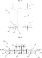
- Additional features and advantages of the present invention will become more apparent from the illustrative and thus non-limiting description of a preferred but not exclusive embodiment of a housing device for housing fixing elements and fixing system for fixing a connection bar for connecting layers of concrete and a prefabricated plinth comprising such a fixing system, as illustrated in the appended drawings, in which:
-
figure 1 illustrates a housing device for housing fixing elements for fixing a connection bar, according to the present invention, in perspective view; -
figure 2 shows a top view of the housing device offigure 1 ; -
figure 3 illustrates a front view of the housing device offigure 1 ; -
figure 4 illustrates the housing device offigure 1 to which an extension tube is applied, in a sectioned front view; -
figure 5 illustrates a sectioned front view of a first embodiment of a fixing system for fixing a connection bar for connecting layers of concrete, according to the present invention; -
figure 6 illustrates the fixing system offigure 5 to which a connection bar is applied, in a perspective view; -
figure 7 shows a sectioned front view of a second embodiment of a fixing system according to the present invention; -
figure 8 illustrates the fixing system offigure 7 to which a connection bar is mounted, in a perspective view; -
figure 9 shows an alternative embodiment of the screwing means from above of the fixing system according to the present invention; -
figures 10 and11 illustrate a perspective view and a front view, respectively without and with the hidden lines, of an alternative embodiment of the fixing system, comprising the screwing means from above offigure 9 ; -
figure 12 illustrates a prefabricated plinth, according to the present invention, in a sectioned front view. - With reference to the figures,
number 1 indicates a housing device for housing fixing elements for fixing a connection bar for connecting layers of concrete. - In the connection between overlapped
layers 101 of concrete, for example in a plinth, a threadedconnection bar 102 is used. Such bar crosses the various layers. Thehousing device 1 is designed to be positioned inside each layer to delimit an area in which to house and host fixing elements (in particular, screwing) for the bar. - The
housing device 1 comprises ahollow body 2 having a cylindrical extension between a first and asecond end hollow body 2 comprises abottom portion 3 at thesecond end 2b. In other words, thehollow body 2 is substantially cup or glass shaped. - The
bottom portion 3 has an opening 4 towards the outside. - The
housing device 1 comprises ahollow projection 5 connected to thebottom portion 3 so as to communicate with theopening 4. Thehollow projection 5 originates from thebottom portion 3 and extends away therefrom. Preferably, thehollow projection 5 extends according to a substantially parallel direction to the extension direction of thehollow body 2. - In other words, the
hollow projection 5 is a small tube. - The
housing device 1 may be made of plastic material, ferrous and nonferrous material, polyamide (e.g. PA6, PA 6.6), first smelting aluminium, cast iron (e.g. hot dip galvanized spheroidal, grey cast iron...), steel, etc. The important point is that the material is able to reach a predefined resistance threshold. - Preferably, the
housing device 1 comprises a connectingportion 6 between thehollow body 2 and thehollow projection 5. In particular, the connectingportion 6 originates from thebottom portion 3 of thehollow body 2 with an extension inclined towards thehollow projection 5. - In particular, the connecting
portion 6 defines corners connected with surface portions having a parallel direction to the extension direction of thehollow body 2. - In this way, while the cement is being poured, air does not get trapped and so-called air bubbles which weaken the structure are not formed. Furthermore, the described geometry prevents the excessive use of material as would happen in the case of a direct connection between the
hollow body 2 and thehollow projection 5. - Preferably, the inclination of the connecting
portion 6 with respect to the horizontal is comprised between 5° and 20°. The optimal inclination is identified as 12°. - Preferably, the
hollow body 2 and thehollow projection 5 are made of a single piece. - Preferably, the
housing device 1 comprises an abutment means 7 for positioning anextension tube 8 in thehollow projection 5. The abutment means 7 is at theopening 4. - In the embodiment described and illustrated herein, the abutment means 7 is defined by a
bottom portion area 3 which projects in a cantilever fashion at theopening 4. In particular, thehollow projection 5 has a through hole having greater dimensions than theopening 4 so as to define abottom portion area 3 which faces and projects inwards with respect to thehollow projection 5 to offer an abutment for thetube 8. In other words, the abutment means 7 is defined by a circular tooth which projects inwards on theopening 4. - Preferably, the
housing device 1 comprises a plurality offlaps 9 arranged around thehollow body 2. - Preferably, the
flaps 9 are uniformly distributed along the cylindrical surface of thehollow body 2. Preferably, theflaps 9 are arranged at the same height as the cylindricalhollow body 2. Preferably, theflaps 9 are arranged on thehollow body 2 so as to be circumferentially equidistant. Theflaps 9 prevent thehousing device 1 from rotating and at the same time prevent detachment from the cement. - In the embodiment described and illustrated herein, the
flaps 9 are perforated. In this way, thehousing device 1 can still be anchored to the steel reinforcement. - Preferably, the
flaps 9 are positioned on thehollow body 2 at a shorter distance from thesecond end 2b with respect to the distance from thefirst end 2a. In other words, theflaps 9 are arranged close to thesecond end 2b. Thus, they leave a suitable space for connection with the reinforcement, also the surface one. - A fixing system for fixing a connection bar for connecting layers of concrete, according to the present invention, is indicated by
number 10 and described below. - The fixing
system 10 comprises thehousing device 1 according to what has been described above. - The fixing
system 10 comprises afirst plate 11 for sharing the compressive load arranged inside thehollow body 2 of thehousing device 1. In particular, one side of thefirst plate 11 is in contact with thebottom portion 3. - A
second plate 12 for sharing the tensile load is arranged at an opposite side of thefirst plate 11 with respect to thebottom portion 3. - The fixing
system 10 comprises anut 13 interposed between the first and thesecond plate washer 18 is interposed between thenut 13 and thefirst plate 11. - The two
plates - Preferably, the fixing
system 10 comprises anextension tube 8 having an end portion inserted into thehollow projection 5. - The
extension tube 8 has a containment function, of a passage element. Theextension tube 8 can have different heights for different heights of blocks. In this way, the fixingsystem 10 can be adapted to different slab formats. - Preferably, the
extension tube 8 is made of PVC or PE or aluminium or steel or alloys. Any material able to contain concrete can be used, as theextension tube 8 does not have a structural function. - The
extension tube 8 and the abutment means 7 are sized so that theextension tube 8 does not create any obstacles to the insertion of aconnection bar 102. - Preferably, the assembly between the
housing device 1 and theextension tube 8 only takes place by friction. - According to a first embodiment, illustrated in
figures 5 and6 , the fixingsystem 10 comprises, as just described, ahousing device 1. - The fixing
system 10 is buried in alayer 101 of concrete and acts both as a tubular opening for the positioning of aconnection bar 102 for connecting the layers and as an assembly point for the bar. - According to a second embodiment, illustrated in
figures 7 and8 , the fixingsystem 10 comprises afurther housing device 1. Thehollow projection 5 of thefurther housing device 1 is mounted at an opposite end of theextension tube 8. In other words, theconnection system 10 comprises twohousing devices 1 facing towards each other (in particular, thehollow projections 5 face each other) and are spaced apart from theextension tube 8. - In this case, the fixing
system 10 comprises a screwing means from above 14 of a connection bar. Such screwing means from above 14 is arranged in thefurther housing device 1. - In the embodiment described and illustrated herein, the screwing means from above 14 comprises a
thick washer 15 and a threadedportion 16 associated therewith for the screwing of the connection bar. - The
thick washer 15 has a throughhole 18 for the passage of the connection bar between layers. - In an embodiment, illustrated in
figures 5-8 , the threadedportion 16 is afforded on a nut mounted on thethick washer 15. The throughhole 18 of thethick washer 15 communicates with the through hole of the threadednut 16 so that the connection bar passes through thethick washer 15 and is screwed to the threadednut 16, which is located below thethick washer 15 during use. - In an alternative embodiment, illustrated in
figures 9-11 , the threadedportion 16 is afforded directly on thethick washer 15. In this case, the throughhole 18 of thethick washer 15 is threaded. - The presence of screwing means from above of the connection bar between layers greatly increases the safety of the operators and the assembly speed. In fact, in known solutions, it is necessary to connect the bars to the lower slab, fixing them in advance with nuts. Before the installation of the first (lower) layer. This takes place by suspending in the air (holding them with a crane or resting them on high capacity and weight trestles) the lower slabs in order to be able to insert the bars and with the operators who pass below the slabs themselves in order to tighten the nuts. It is clear that the operators are subject to a very high risk. With the implementation of the screwing means from above, the lower slabs are rested directly inside the already prepared excavation and then the bars are screwed into the provided housings operating directly from above (therefore without any need for trestles, without exposing the workers and therefore safely and quickly).
- As is clear, the second embodiment of the fixing
system 10 is used in the lower layer. - Preferably, the
housing device 1 comprises one ormore markings 17 made on thehollow body 2 at predefined areas for the insertion during assembly of a mechanical fixing element, e.g. a screw or rivet. Such mechanical fixing elements operate to hold thethick washer 15 in position. Thethick washer 15 has twotransverse holes 19. A transverse hole means a hole having an extension from a lateral surface of thethick washer 15 towards a central portion, in particular towards the throughhole 18. - In particular, the two
transverse holes 19 are not through holes. Preferably, the twotransverse holes 19 are made on opposite sides with respect to the throughhole 18. Preferably, the twotransverse holes 19 have an extension according to two substantially parallel directions. Preferably, the two directions coincide, i.e. the holes are aligned. - In the embodiment described and illustrated herein, the
thick washer 15 is substantially cylindrical. - In an assembled condition, the
washer 15 is held in position by the insertion of amechanical fixing element 20 through the marking 17 on thehollow body 2 and thetransverse hole 19. - A prefabricated plinth, according to the present invention, is described below.
- The
plinth 100 comprises a plurality of overlappinglayers 101. Eachlayer 101 is formed by a plurality of prefabricated reinforced concrete blocks. - The
plinth 100 comprises at least one threadedconnection bar 102 for structurally connecting thelayers 101 to one another. Preferably, a plurality of connection bars 102 connects thelayers 101 to one another structurally. The description provided below for aconnection bar 102 is to be considered extended to everyconnection bar 102 present in theplinth 100. - The
plinth 100 comprises, for eachconnection bar 102, at least onefixing system 10, according to what is described above, housed in eachlayer 101. Theconnection bar 102 is mounted, i.e. screwed, to each fixingsystem 10. - In particular, each
layer 101 comprises a fixingsystem 10 in a first embodiment thereof (or of a first type), comprising ahousing device 1, whereas in the lower layer 101 a fixingsystem 10 is arranged in the second embodiment thereof (or of a second type). The fixingsystems 10 of the first type are arranged in an upper portion of thelayer 101 so that during assembly by overlapping the blocks, the operators can easily fix theconnection bar 102 step by step to thehousing device 1 of each layer withplates - The fixing
system 10 of the second type is instead arranged in a lower portion of thelower layer 101. Thefurther housing device 1 of the fixingsystem 10 faces downwards. - The
connection bar 102 is fixed at a (lower) end to the screwing means from above 14 of the fixingsystem 10 of thelower layer 101. - In other words, the
connection bar 102 crosses thelayers 101 meeting ahousing device 1 for eachlayer 101 at which it is screwed. In thelower layer 101 it crosses twohousing devices 1, one facing upwards like the previous ones and the other facing downwards, in which the screwing means from above 14 is contained. - From the description given, the features of the housing device for housing fixing elements and fixing system for fixing a connection bar for connecting layers of concrete and of the prefabricated plinth comprising such a fixing system according to the present invention appear clear, as do the advantages thereof.
- In particular, the connected and inclined geometry of the connection portion proposed for the housing device prevents the formation of bubbles of concrete.
- Furthermore, the presence of flaps prevents the accidental movement of the housing device positioned inside the layer. In particular, the presence of the holes on the flaps enables the fixing of the reinforcement device, guaranteeing precise positioning thereof.
- Furthermore, the provision in the fixing system of the lower layer of screwing means from above, once the lower slab is already laid, of the connection bar, greatly facilitates the work of the operators, notably increasing the safety thereof.
- Furthermore, the configuration of the fixing systems described for the plinth makes it possible to easily overcome any yielding of an assembly point. If a connection or fixing element (e.g. the lower nut placed on the first buried block) fails (e.g. due to natural oxidation over time, considering that it is in direct contact with the ground) the other fixing elements, which remain solidly connected to the other overlapping concrete elements, immediately enter into tension. This happens because the transverse connection bar has various assembly points which cooperate, in particular one per layer. In known solutions, instead, the bar is only mounted at the upper and lower end, crossing the intermediate layers without any further assembly points. It follows that the yielding of one of the two connected ends causes the structure to collapse. Furthermore, this arrangement promotes the transmission of the load and its distribution in the elements themselves. The choice to interconnect at every layer the transverse elements and the combination between nuts and plates (which completely fill the internal space of every single housing device) ensures that the tensile/compressive action that a post exerts on every foundation bolt is shared across every single layer. In essence, the tension is shared between the various layers making them cooperate to support the strain and therefore there is relatively low pressure around each fixing element (with a clear structural advantage).
Claims (12)
- A housing device (1) for housing fixing elements for fixing of a connection bar (102) for connecting layers (101) of concrete, comprising:a hollow body (2) having a cylindrical extension between a first and a second end (2a, 2b) and comprising a bottom portion (3) at said second end (2b), said bottom portion (3) having an opening (4) towards the outside;a hollow projection (5) connected to said bottom portion (3) so as to communicate with the opening (4) and having an extension away from it; characterised in that it comprises a plurality of flaps (9) arranged around the hollow body (2).
- The housing device (1) according to claim 1, comprising a connecting portion (6) originating from the bottom portion (3) of the hollow body (2) with an extension inclined towards the hollow projection (5).
- The housing device (1) according to claim 1 or 2, comprising an abutment means (7) for positioning an extension tube (8) in the hollow projection (5), said abutment means (7) being at said opening (4).
- The housing device (1) according to claim 3, wherein the hollow projection (5) has a through hole having greater dimensions than said opening (4) so that a bottom portion area (3) faces and projects inwards with respect to the hollow projection (5) defining an abutment means (7) for the extension tube (8).
- The housing device (1) according to claim 1 wherein the flaps are perforated.
- The housing device (1) according to any one of the preceding claims, wherein the hollow body (2) and the hollow projection (5) are made of a single piece.
- A fixing system (10) for fixing a connection bar (102) for connecting layers (101) of concrete, comprising:a housing device (1) according to any one of the preceding claims;a first plate (11) for sharing the compressive load arranged inside the hollow body (2) of the housing device (1), one side of said first plate (11) being in contact with the bottom portion (3);a second plate (12) for sharing the tensile load at an opposite side of the first plate (12) with respect to the bottom portion (3);a nut (13) interposed between the first and the second plate (11, 12).
- The fixing system (10) according to claim 7, comprising an extension tube (8) having an end portion inserted into the hollow projection (5).
- The fixing system (10) according to claim 8, comprising a further housing device (1) the hollow projection (5) of which is mounted at an opposite end of the extension tube (8), said fixing system (10) comprising a screwing means from above (14) of a connection bar (102) arranged in the further housing device (1).
- The fixing system (10) according to claim 9, wherein said screwing means from above comprises a thick washer (15) and a threaded portion (16) associated therewith for the screwing from above of the connection bar.
- The fixing system (10) according to claim 10, wherein said threaded portion (16) is made in a through hole (18) of the thick washer (15), said thick washer (15) comprising two blind transverse holes (19), said hollow body (2) of the further housing device comprising two markings (17) to enable the insertion of corresponding mechanical fixing elements (20) in the transverse holes (19) so as to keep the thick washer (15) in position.
- A prefabricated plinth (100), comprising:a plurality of overlapped layers (101), each of them formed by a plurality of prefabricated reinforced concrete blocks;at least one connection bar (102) having an extension between the layers (101) for connecting them structurally to one another;at least one fixing system (10) according to any one of claims 8 to 11 housed in each layer (101), said connection bar (102) being screwed in each layer (101) to the corresponding fixing system (10).
Applications Claiming Priority (1)
| Application Number | Priority Date | Filing Date | Title |
|---|---|---|---|
| IT102021000016919A IT202100016919A1 (en) | 2021-06-28 | 2021-06-28 | HOUSING DEVICE FOR FASTENING ELEMENTS AND SYSTEM FOR FIXING A CONCRETE LAYER CONNECTING BAR AND PREFABRICATED BASE INCLUDING SUCH FIXING SYSTEM |
Publications (3)
| Publication Number | Publication Date |
|---|---|
| EP4112817A1 true EP4112817A1 (en) | 2023-01-04 |
| EP4112817C0 EP4112817C0 (en) | 2024-05-29 |
| EP4112817B1 EP4112817B1 (en) | 2024-05-29 |
Family
ID=77802092
Family Applications (1)
| Application Number | Title | Priority Date | Filing Date |
|---|---|---|---|
| EP22176373.3A Active EP4112817B1 (en) | 2021-06-28 | 2022-05-31 | Housing device for housing fixing elements of a connection bar for connecting layers of concrete; fixing system for fixing a connection bar; and prefabricated plinth comprising such a fixing system |
Country Status (2)
| Country | Link |
|---|---|
| EP (1) | EP4112817B1 (en) |
| IT (1) | IT202100016919A1 (en) |
Cited By (1)
| Publication number | Priority date | Publication date | Assignee | Title |
|---|---|---|---|---|
| CN120854148A (en) * | 2025-09-22 | 2025-10-28 | 江苏迈盛新材料有限公司 | A processing device for mutual inductor glue filling |
Citations (6)
| Publication number | Priority date | Publication date | Assignee | Title |
|---|---|---|---|---|
| DE2304132A1 (en) * | 1973-01-29 | 1974-08-01 | Gemex Gmbh & Co Kg | FASTENING DEVICE FOR MACHINERY ON FOUNDATIONS |
| WO2001063056A2 (en) * | 2000-02-24 | 2001-08-30 | Giltek Telecommunications Ltd. | Foundation for a tower and a method for its deployment on site |
| JP2002212963A (en) * | 2001-01-17 | 2002-07-31 | Sumitomo Densetsu Corp | Pillar foundation members |
| DE102007033983B3 (en) | 2007-07-19 | 2008-09-04 | Rail.One Gmbh | Concrete sleeper for rails has cavity formed in interior of plug filled with compressible material |
| EP2977529A1 (en) * | 2014-07-21 | 2016-01-27 | INTEGERIX Planungsbüro GmbH | Single foundation |
| US20160024741A1 (en) * | 2014-07-23 | 2016-01-28 | Franklin Brown | Tower foundation guide rod nut |
-
2021
- 2021-06-28 IT IT102021000016919A patent/IT202100016919A1/en unknown
-
2022
- 2022-05-31 EP EP22176373.3A patent/EP4112817B1/en active Active
Patent Citations (6)
| Publication number | Priority date | Publication date | Assignee | Title |
|---|---|---|---|---|
| DE2304132A1 (en) * | 1973-01-29 | 1974-08-01 | Gemex Gmbh & Co Kg | FASTENING DEVICE FOR MACHINERY ON FOUNDATIONS |
| WO2001063056A2 (en) * | 2000-02-24 | 2001-08-30 | Giltek Telecommunications Ltd. | Foundation for a tower and a method for its deployment on site |
| JP2002212963A (en) * | 2001-01-17 | 2002-07-31 | Sumitomo Densetsu Corp | Pillar foundation members |
| DE102007033983B3 (en) | 2007-07-19 | 2008-09-04 | Rail.One Gmbh | Concrete sleeper for rails has cavity formed in interior of plug filled with compressible material |
| EP2977529A1 (en) * | 2014-07-21 | 2016-01-27 | INTEGERIX Planungsbüro GmbH | Single foundation |
| US20160024741A1 (en) * | 2014-07-23 | 2016-01-28 | Franklin Brown | Tower foundation guide rod nut |
Cited By (1)
| Publication number | Priority date | Publication date | Assignee | Title |
|---|---|---|---|---|
| CN120854148A (en) * | 2025-09-22 | 2025-10-28 | 江苏迈盛新材料有限公司 | A processing device for mutual inductor glue filling |
Also Published As
| Publication number | Publication date |
|---|---|
| EP4112817C0 (en) | 2024-05-29 |
| EP4112817B1 (en) | 2024-05-29 |
| IT202100016919A1 (en) | 2022-12-28 |
Similar Documents
| Publication | Publication Date | Title |
|---|---|---|
| JP2019500525A (en) | Assembled steel pipe casing reinforced concrete composite node and mounting method | |
| KR100955788B1 (en) | A pile head reinforcement structure ofprecastconcrete pile | |
| KR102429105B1 (en) | Pier With Stress Reinforced Steel Composite Member | |
| EP4112817B1 (en) | Housing device for housing fixing elements of a connection bar for connecting layers of concrete; fixing system for fixing a connection bar; and prefabricated plinth comprising such a fixing system | |
| CN109235662A (en) | A kind of column board connecting equipment comprising multiple shear connector | |
| KR102269140B1 (en) | Support Structure for Construction of RC Beam Mold, And Method for Construction of RC Beam | |
| CN104047233A (en) | Method for construction of continuous beam linear segment without floor stand | |
| EA003592B1 (en) | Method for constructing structures useful as catwalks and building scaffolds on slopes | |
| JP2019108701A (en) | Fence for safety measures of reinforced soil wall construction | |
| KR101257752B1 (en) | Non-welding type seismic reinforcing structure and method for column using cft | |
| JP3146282U (en) | Protective fence | |
| KR20160092001A (en) | Support post structure for safety fence | |
| KR101714159B1 (en) | Device For Preventing Bending Moment Transfer And Rahmen Bridge Using Thereof | |
| KR20090011361A (en) | Formwork system for concrete slab of filled steel pipe girder bridge | |
| KR100808291B1 (en) | Girder Type Bridge Safety Device | |
| EP0058851A1 (en) | Building structure of prefabricated elements | |
| CN114214952A (en) | Anti-overturning device and method for side beam of small box beam of prefabricated anti-collision wall | |
| JP2002275833A (en) | Continuous girder method and girder structure for existing bridges | |
| CN209923936U (en) | Joint structure of upright post, supporting beam and plate in foundation pit engineering | |
| CN210738580U (en) | Mould hanging device for hoisting hole | |
| CN110805261A (en) | Steel platform steel beam structure based on prestress reinforcement and construction method | |
| JP2512963B2 (en) | Reinforced concrete slab construction method | |
| KR102521965B1 (en) | Bridge having reinforced structure for transverse direction and point part | |
| CN222923784U (en) | Assembled piping lane bearing structure | |
| CN217325837U (en) | Bracket buried part node capable of preventing side turning and falling |
Legal Events
| Date | Code | Title | Description |
|---|---|---|---|
| PUAI | Public reference made under article 153(3) epc to a published international application that has entered the european phase |
Free format text: ORIGINAL CODE: 0009012 |
|
| STAA | Information on the status of an ep patent application or granted ep patent |
Free format text: STATUS: THE APPLICATION HAS BEEN PUBLISHED |
|
| AK | Designated contracting states |
Kind code of ref document: A1 Designated state(s): AL AT BE BG CH CY CZ DE DK EE ES FI FR GB GR HR HU IE IS IT LI LT LU LV MC MK MT NL NO PL PT RO RS SE SI SK SM TR |
|
| STAA | Information on the status of an ep patent application or granted ep patent |
Free format text: STATUS: REQUEST FOR EXAMINATION WAS MADE |
|
| 17P | Request for examination filed |
Effective date: 20230130 |
|
| RBV | Designated contracting states (corrected) |
Designated state(s): AL AT BE BG CH CY CZ DE DK EE ES FI FR GB GR HR HU IE IS IT LI LT LU LV MC MK MT NL NO PL PT RO RS SE SI SK SM TR |
|
| P01 | Opt-out of the competence of the unified patent court (upc) registered |
Effective date: 20230515 |
|
| GRAP | Despatch of communication of intention to grant a patent |
Free format text: ORIGINAL CODE: EPIDOSNIGR1 |
|
| STAA | Information on the status of an ep patent application or granted ep patent |
Free format text: STATUS: GRANT OF PATENT IS INTENDED |
|
| INTG | Intention to grant announced |
Effective date: 20240319 |
|
| GRAS | Grant fee paid |
Free format text: ORIGINAL CODE: EPIDOSNIGR3 |
|
| GRAA | (expected) grant |
Free format text: ORIGINAL CODE: 0009210 |
|
| STAA | Information on the status of an ep patent application or granted ep patent |
Free format text: STATUS: THE PATENT HAS BEEN GRANTED |
|
| AK | Designated contracting states |
Kind code of ref document: B1 Designated state(s): AL AT BE BG CH CY CZ DE DK EE ES FI FR GB GR HR HU IE IS IT LI LT LU LV MC MK MT NL NO PL PT RO RS SE SI SK SM TR |
|
| REG | Reference to a national code |
Ref country code: CH Ref legal event code: EP |
|
| REG | Reference to a national code |
Ref country code: IE Ref legal event code: FG4D |
|
| REG | Reference to a national code |
Ref country code: DE Ref legal event code: R096 Ref document number: 602022003648 Country of ref document: DE |
|
| U01 | Request for unitary effect filed |
Effective date: 20240611 |
|
| P04 | Withdrawal of opt-out of the competence of the unified patent court (upc) registered |
Free format text: CASE NUMBER: APP_36279/2024 Effective date: 20240617 |
|
| U07 | Unitary effect registered |
Designated state(s): AT BE BG DE DK EE FI FR IT LT LU LV MT NL PT SE SI Effective date: 20240620 |
|
| U20 | Renewal fee for the european patent with unitary effect paid |
Year of fee payment: 3 Effective date: 20240620 |
|
| PG25 | Lapsed in a contracting state [announced via postgrant information from national office to epo] |
Ref country code: IS Free format text: LAPSE BECAUSE OF FAILURE TO SUBMIT A TRANSLATION OF THE DESCRIPTION OR TO PAY THE FEE WITHIN THE PRESCRIBED TIME-LIMIT Effective date: 20240929 |
|
| PG25 | Lapsed in a contracting state [announced via postgrant information from national office to epo] |
Ref country code: HR Free format text: LAPSE BECAUSE OF FAILURE TO SUBMIT A TRANSLATION OF THE DESCRIPTION OR TO PAY THE FEE WITHIN THE PRESCRIBED TIME-LIMIT Effective date: 20240529 |
|
| PG25 | Lapsed in a contracting state [announced via postgrant information from national office to epo] |
Ref country code: GR Free format text: LAPSE BECAUSE OF FAILURE TO SUBMIT A TRANSLATION OF THE DESCRIPTION OR TO PAY THE FEE WITHIN THE PRESCRIBED TIME-LIMIT Effective date: 20240830 |
|
| PG25 | Lapsed in a contracting state [announced via postgrant information from national office to epo] |
Ref country code: ES Free format text: LAPSE BECAUSE OF FAILURE TO SUBMIT A TRANSLATION OF THE DESCRIPTION OR TO PAY THE FEE WITHIN THE PRESCRIBED TIME-LIMIT Effective date: 20240529 |
|
| PG25 | Lapsed in a contracting state [announced via postgrant information from national office to epo] |
Ref country code: PL Free format text: LAPSE BECAUSE OF FAILURE TO SUBMIT A TRANSLATION OF THE DESCRIPTION OR TO PAY THE FEE WITHIN THE PRESCRIBED TIME-LIMIT Effective date: 20240529 |
|
| PG25 | Lapsed in a contracting state [announced via postgrant information from national office to epo] |
Ref country code: PL Free format text: LAPSE BECAUSE OF FAILURE TO SUBMIT A TRANSLATION OF THE DESCRIPTION OR TO PAY THE FEE WITHIN THE PRESCRIBED TIME-LIMIT Effective date: 20240529 Ref country code: NO Free format text: LAPSE BECAUSE OF FAILURE TO SUBMIT A TRANSLATION OF THE DESCRIPTION OR TO PAY THE FEE WITHIN THE PRESCRIBED TIME-LIMIT Effective date: 20240829 Ref country code: IS Free format text: LAPSE BECAUSE OF FAILURE TO SUBMIT A TRANSLATION OF THE DESCRIPTION OR TO PAY THE FEE WITHIN THE PRESCRIBED TIME-LIMIT Effective date: 20240929 Ref country code: HR Free format text: LAPSE BECAUSE OF FAILURE TO SUBMIT A TRANSLATION OF THE DESCRIPTION OR TO PAY THE FEE WITHIN THE PRESCRIBED TIME-LIMIT Effective date: 20240529 Ref country code: GR Free format text: LAPSE BECAUSE OF FAILURE TO SUBMIT A TRANSLATION OF THE DESCRIPTION OR TO PAY THE FEE WITHIN THE PRESCRIBED TIME-LIMIT Effective date: 20240830 Ref country code: ES Free format text: LAPSE BECAUSE OF FAILURE TO SUBMIT A TRANSLATION OF THE DESCRIPTION OR TO PAY THE FEE WITHIN THE PRESCRIBED TIME-LIMIT Effective date: 20240529 Ref country code: RS Free format text: LAPSE BECAUSE OF FAILURE TO SUBMIT A TRANSLATION OF THE DESCRIPTION OR TO PAY THE FEE WITHIN THE PRESCRIBED TIME-LIMIT Effective date: 20240829 |
|
| P05 | Withdrawal of opt-out of the competence of the unified patent court (upc) changed |
Free format text: CASE NUMBER: APP_36279/2024 Effective date: 20240620 |
|
| PG25 | Lapsed in a contracting state [announced via postgrant information from national office to epo] |
Ref country code: CZ Free format text: LAPSE BECAUSE OF FAILURE TO SUBMIT A TRANSLATION OF THE DESCRIPTION OR TO PAY THE FEE WITHIN THE PRESCRIBED TIME-LIMIT Effective date: 20240529 |
|
| PG25 | Lapsed in a contracting state [announced via postgrant information from national office to epo] |
Ref country code: SK Free format text: LAPSE BECAUSE OF FAILURE TO SUBMIT A TRANSLATION OF THE DESCRIPTION OR TO PAY THE FEE WITHIN THE PRESCRIBED TIME-LIMIT Effective date: 20240529 Ref country code: RO Free format text: LAPSE BECAUSE OF FAILURE TO SUBMIT A TRANSLATION OF THE DESCRIPTION OR TO PAY THE FEE WITHIN THE PRESCRIBED TIME-LIMIT Effective date: 20240529 |
|
| PG25 | Lapsed in a contracting state [announced via postgrant information from national office to epo] |
Ref country code: SM Free format text: LAPSE BECAUSE OF FAILURE TO SUBMIT A TRANSLATION OF THE DESCRIPTION OR TO PAY THE FEE WITHIN THE PRESCRIBED TIME-LIMIT Effective date: 20240529 |
|
| PG25 | Lapsed in a contracting state [announced via postgrant information from national office to epo] |
Ref country code: SM Free format text: LAPSE BECAUSE OF FAILURE TO SUBMIT A TRANSLATION OF THE DESCRIPTION OR TO PAY THE FEE WITHIN THE PRESCRIBED TIME-LIMIT Effective date: 20240529 Ref country code: SK Free format text: LAPSE BECAUSE OF FAILURE TO SUBMIT A TRANSLATION OF THE DESCRIPTION OR TO PAY THE FEE WITHIN THE PRESCRIBED TIME-LIMIT Effective date: 20240529 Ref country code: RO Free format text: LAPSE BECAUSE OF FAILURE TO SUBMIT A TRANSLATION OF THE DESCRIPTION OR TO PAY THE FEE WITHIN THE PRESCRIBED TIME-LIMIT Effective date: 20240529 Ref country code: CZ Free format text: LAPSE BECAUSE OF FAILURE TO SUBMIT A TRANSLATION OF THE DESCRIPTION OR TO PAY THE FEE WITHIN THE PRESCRIBED TIME-LIMIT Effective date: 20240529 |
|
| PG25 | Lapsed in a contracting state [announced via postgrant information from national office to epo] |
Ref country code: MC Free format text: LAPSE BECAUSE OF FAILURE TO SUBMIT A TRANSLATION OF THE DESCRIPTION OR TO PAY THE FEE WITHIN THE PRESCRIBED TIME-LIMIT Effective date: 20240529 |
|
| PLBE | No opposition filed within time limit |
Free format text: ORIGINAL CODE: 0009261 |
|
| STAA | Information on the status of an ep patent application or granted ep patent |
Free format text: STATUS: NO OPPOSITION FILED WITHIN TIME LIMIT |
|
| PG25 | Lapsed in a contracting state [announced via postgrant information from national office to epo] |
Ref country code: IE Free format text: LAPSE BECAUSE OF NON-PAYMENT OF DUE FEES Effective date: 20240531 |
|
| 26N | No opposition filed |
Effective date: 20250303 |
|
| U20 | Renewal fee for the european patent with unitary effect paid |
Year of fee payment: 4 Effective date: 20250529 |
|
| PG25 | Lapsed in a contracting state [announced via postgrant information from national office to epo] |
Ref country code: CY Free format text: LAPSE BECAUSE OF FAILURE TO SUBMIT A TRANSLATION OF THE DESCRIPTION OR TO PAY THE FEE WITHIN THE PRESCRIBED TIME-LIMIT; INVALID AB INITIO Effective date: 20220531 |
|
| REG | Reference to a national code |
Ref country code: CH Ref legal event code: H13 Free format text: ST27 STATUS EVENT CODE: U-0-0-H10-H13 (AS PROVIDED BY THE NATIONAL OFFICE) Effective date: 20251223 |
|
| PG25 | Lapsed in a contracting state [announced via postgrant information from national office to epo] |
Ref country code: CH Free format text: LAPSE BECAUSE OF NON-PAYMENT OF DUE FEES Effective date: 20250531 |
|
| PG25 | Lapsed in a contracting state [announced via postgrant information from national office to epo] |
Ref country code: HU Free format text: LAPSE BECAUSE OF FAILURE TO SUBMIT A TRANSLATION OF THE DESCRIPTION OR TO PAY THE FEE WITHIN THE PRESCRIBED TIME-LIMIT; INVALID AB INITIO Effective date: 20220531 |
|
| PG25 | Lapsed in a contracting state [announced via postgrant information from national office to epo] |
Ref country code: TR Free format text: LAPSE BECAUSE OF FAILURE TO SUBMIT A TRANSLATION OF THE DESCRIPTION OR TO PAY THE FEE WITHIN THE PRESCRIBED TIME-LIMIT Effective date: 20240529 |
|
| PG25 | Lapsed in a contracting state [announced via postgrant information from national office to epo] |
Ref country code: CH Free format text: THE PATENT HAS BEEN ANNULLED BY A DECISION OF A NATIONAL AUTHORITY Effective date: 20250531 |
|
| U20 | Renewal fee for the european patent with unitary effect paid |
Year of fee payment: 5 Effective date: 20260527 |