EP4112802B1 - Vorrichtung zur behandlung von kleidung - Google Patents
Vorrichtung zur behandlung von kleidung Download PDFInfo
- Publication number
- EP4112802B1 EP4112802B1 EP21759901.8A EP21759901A EP4112802B1 EP 4112802 B1 EP4112802 B1 EP 4112802B1 EP 21759901 A EP21759901 A EP 21759901A EP 4112802 B1 EP4112802 B1 EP 4112802B1
- Authority
- EP
- European Patent Office
- Prior art keywords
- drum
- coil
- treating apparatus
- laundry treating
- circuit
- Prior art date
- Legal status (The legal status is an assumption and is not a legal conclusion. Google has not performed a legal analysis and makes no representation as to the accuracy of the status listed.)
- Active
Links
Images




Classifications
-
- D—TEXTILES; PAPER
- D06—TREATMENT OF TEXTILES OR THE LIKE; LAUNDERING; FLEXIBLE MATERIALS NOT OTHERWISE PROVIDED FOR
- D06F—LAUNDERING, DRYING, IRONING, PRESSING OR FOLDING TEXTILE ARTICLES
- D06F34/00—Details of control systems for washing machines, washer-dryers or laundry dryers
- D06F34/14—Arrangements for detecting or measuring specific parameters
- D06F34/20—Parameters relating to constructional components, e.g. door sensors
-
- D—TEXTILES; PAPER
- D06—TREATMENT OF TEXTILES OR THE LIKE; LAUNDERING; FLEXIBLE MATERIALS NOT OTHERWISE PROVIDED FOR
- D06F—LAUNDERING, DRYING, IRONING, PRESSING OR FOLDING TEXTILE ARTICLES
- D06F34/00—Details of control systems for washing machines, washer-dryers or laundry dryers
- D06F34/10—Power supply arrangements, e.g. stand-by circuits
-
- D—TEXTILES; PAPER
- D06—TREATMENT OF TEXTILES OR THE LIKE; LAUNDERING; FLEXIBLE MATERIALS NOT OTHERWISE PROVIDED FOR
- D06F—LAUNDERING, DRYING, IRONING, PRESSING OR FOLDING TEXTILE ARTICLES
- D06F34/00—Details of control systems for washing machines, washer-dryers or laundry dryers
- D06F34/14—Arrangements for detecting or measuring specific parameters
- D06F34/26—Condition of the drying air, e.g. air humidity or temperature
-
- D—TEXTILES; PAPER
- D06—TREATMENT OF TEXTILES OR THE LIKE; LAUNDERING; FLEXIBLE MATERIALS NOT OTHERWISE PROVIDED FOR
- D06F—LAUNDERING, DRYING, IRONING, PRESSING OR FOLDING TEXTILE ARTICLES
- D06F39/00—Details of washing machines not specific to a single type of machines covered by groups D06F9/00 - D06F27/00
- D06F39/04—Heating arrangements
-
- D—TEXTILES; PAPER
- D06—TREATMENT OF TEXTILES OR THE LIKE; LAUNDERING; FLEXIBLE MATERIALS NOT OTHERWISE PROVIDED FOR
- D06F—LAUNDERING, DRYING, IRONING, PRESSING OR FOLDING TEXTILE ARTICLES
- D06F58/00—Domestic laundry dryers
- D06F58/20—General details of domestic laundry dryers
- D06F58/26—Heating arrangements, e.g. gas heating equipment
-
- D—TEXTILES; PAPER
- D06—TREATMENT OF TEXTILES OR THE LIKE; LAUNDERING; FLEXIBLE MATERIALS NOT OTHERWISE PROVIDED FOR
- D06F—LAUNDERING, DRYING, IRONING, PRESSING OR FOLDING TEXTILE ARTICLES
- D06F58/00—Domestic laundry dryers
- D06F58/32—Control of operations performed in domestic laundry dryers
- D06F58/34—Control of operations performed in domestic laundry dryers characterised by the purpose or target of the control
- D06F58/36—Control of operational steps, e.g. for optimisation or improvement of operational steps depending on the condition of the laundry
- D06F58/38—Control of operational steps, e.g. for optimisation or improvement of operational steps depending on the condition of the laundry of drying, e.g. to achieve the target humidity
- D06F58/40—Control of the initial heating of the drying chamber to its operating temperature
-
- H—ELECTRICITY
- H05—ELECTRIC TECHNIQUES NOT OTHERWISE PROVIDED FOR
- H05B—ELECTRIC HEATING; ELECTRIC LIGHT SOURCES NOT OTHERWISE PROVIDED FOR; CIRCUIT ARRANGEMENTS FOR ELECTRIC LIGHT SOURCES, IN GENERAL
- H05B6/00—Heating by electric, magnetic or electromagnetic fields
- H05B6/02—Induction heating
- H05B6/06—Control, e.g. of temperature, of power
-
- H—ELECTRICITY
- H05—ELECTRIC TECHNIQUES NOT OTHERWISE PROVIDED FOR
- H05B—ELECTRIC HEATING; ELECTRIC LIGHT SOURCES NOT OTHERWISE PROVIDED FOR; CIRCUIT ARRANGEMENTS FOR ELECTRIC LIGHT SOURCES, IN GENERAL
- H05B6/00—Heating by electric, magnetic or electromagnetic fields
- H05B6/02—Induction heating
- H05B6/10—Induction heating apparatus, other than furnaces, for specific applications
-
- D—TEXTILES; PAPER
- D06—TREATMENT OF TEXTILES OR THE LIKE; LAUNDERING; FLEXIBLE MATERIALS NOT OTHERWISE PROVIDED FOR
- D06F—LAUNDERING, DRYING, IRONING, PRESSING OR FOLDING TEXTILE ARTICLES
- D06F2103/00—Parameters monitored or detected for the control of domestic laundry washing machines, washer-dryers or laundry dryers
- D06F2103/44—Current or voltage
-
- D—TEXTILES; PAPER
- D06—TREATMENT OF TEXTILES OR THE LIKE; LAUNDERING; FLEXIBLE MATERIALS NOT OTHERWISE PROVIDED FOR
- D06F—LAUNDERING, DRYING, IRONING, PRESSING OR FOLDING TEXTILE ARTICLES
- D06F2103/00—Parameters monitored or detected for the control of domestic laundry washing machines, washer-dryers or laundry dryers
- D06F2103/52—Parameters monitored or detected for the control of domestic laundry washing machines, washer-dryers or laundry dryers related to electric heating means, e.g. temperature or voltage
-
- D—TEXTILES; PAPER
- D06—TREATMENT OF TEXTILES OR THE LIKE; LAUNDERING; FLEXIBLE MATERIALS NOT OTHERWISE PROVIDED FOR
- D06F—LAUNDERING, DRYING, IRONING, PRESSING OR FOLDING TEXTILE ARTICLES
- D06F2105/00—Systems or parameters controlled or affected by the control systems of washing machines, washer-dryers or laundry dryers
- D06F2105/28—Electric heating
-
- D—TEXTILES; PAPER
- D06—TREATMENT OF TEXTILES OR THE LIKE; LAUNDERING; FLEXIBLE MATERIALS NOT OTHERWISE PROVIDED FOR
- D06F—LAUNDERING, DRYING, IRONING, PRESSING OR FOLDING TEXTILE ARTICLES
- D06F23/00—Washing machines with receptacles, e.g. perforated, having a rotary movement, e.g. oscillatory movement, the receptacle serving both for washing and for centrifugally separating water from the laundry
- D06F23/02—Washing machines with receptacles, e.g. perforated, having a rotary movement, e.g. oscillatory movement, the receptacle serving both for washing and for centrifugally separating water from the laundry and rotating or oscillating about a horizontal axis
-
- D—TEXTILES; PAPER
- D06—TREATMENT OF TEXTILES OR THE LIKE; LAUNDERING; FLEXIBLE MATERIALS NOT OTHERWISE PROVIDED FOR
- D06F—LAUNDERING, DRYING, IRONING, PRESSING OR FOLDING TEXTILE ARTICLES
- D06F25/00—Washing machines with receptacles, e.g. perforated, having a rotary movement, e.g. oscillatory movement, the receptacle serving both for washing and for centrifugally separating water from the laundry and having further drying means, e.g. using hot air
Definitions
- the present invention relates to a laundry treating apparatus.
- a laundry treating apparatus may include a washing machine, a dryer, a device for refreshing clothes, and the like.
- the washing machine may be a washing machine having a drying function.
- a drum accommodating laundry is rotatably provided in a tub that provides a space for storing water. Through holes are formed in such a drum, so that water in the tub flows into the drum. In this state, when the drum is rotated, the laundry in the drum flows and contamination of the laundry is removed.
- Such a washing machine is also provided with a heater for heating the water in the tub.
- the heater is operated in a state of being submerged in water in the tub, so it is common to directly heat the water.
- this type of heater since this type of heater must always be operated in a state of being submerged in water at all times for safety reasons, it can be used for heating the water in the tub, but it is not suitable for heating the air in the drum in a state where there is no water in the tub, or for heating wet laundry before spin-drying.
- Such a washing machine in which a drum is heated by an induction heating system has been used.
- a washing machine may be configured to have a heat sensor disposed between the drum and a tank (or tub) to detect the temperature of water or air in the tank.
- the temperature of the drum is inevitably estimated based on the temperature of water or air. Meanwhile, the temperature of the drum is sensitively fluctuated according to the output of an induction heating system, but the temperature of water or air is slowly fluctuated. Therefore, the value detected by a heat sensor may not accurately reflect the temperature fluctuation of the drum.
- US Patent Application Publication No. US 2018/0148886 discloses a method of estimating a temperature by using a characteristic change of drum according to a temperature, in particular, by using an inductance change.
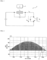
- FIG. 1 shows a resonant circuit for using such a method.
- the driving of a power device Q1 is turned off near a zero crossing of system voltage by using a resonance circuit 2, and at this time, resonance frequency (fres) can be measured by using an autonomous resonant voltage.
- the temperature of a drum 1 (load) can be estimated through the change in inductance (Leq) according to the temperature change.
- FIG. 2 shows a voltage waveform when measuring a resonance frequency
- FIG. 3 shows an enlarged view of a portion A of FIG. 2 .
- the resonance frequency (fres) changes by about 0.015% when the load temperature changes by 1°C. That is, it can be seen that the fluctuation of the resonance frequency (fres) according to the temperature change is too small to estimate the temperature by using the resonance frequency.
- the change in inductance (Leq) fluctuates by 0.03%/°C. That is, it can fluctuate by 0.03% depending on the temperature.
- the capacitance (Ceq) in the resonant frequency (fres) calculation formula should be less than or equal to 0.003% depending on a dispersion of components and a fluctuation dispersion according to a temperature.
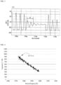
- FIG. 4 is a graph illustrating a relationship between a temperature and a resonance frequency when estimating a temperature by using a resonance frequency.
- an error of the estimated temperature may occur by about ⁇ 10°C or more.
- accuracy within ⁇ 5°C is required.
- An object of the present invention is to solve the above and other problems.
- Another object of the present invention is to provide a laundry treating apparatus, such as a dryer which can accurately estimate a temperature of a drum, a washing machine, a washing machine-and-dryer, and an apparatus for refreshing clothes.
- a laundry treating apparatus such as a dryer which can accurately estimate a temperature of a drum, a washing machine, a washing machine-and-dryer, and an apparatus for refreshing clothes.
- Another object is to provide a laundry treating apparatus capable of heating a drum by an induction heater and accurately estimating the temperature of the drum.
- Another object of the present invention is to provide a laundry treating apparatus capable of accurately estimating the temperature of the drum by minimizing the influence of a magnetic field generated by the induction heater.
- Another object of the present invention is to provide a laundry treating apparatus capable of accurately estimating the temperature of the drum regardless of a distance between a load (drum) and a tub.
- Another object of the present invention is to provide a laundry treating apparatus capable of estimating the temperature of a rotating load (drum).
- Another object of the present invention is to provide a laundry treating apparatus capable of continuously estimating a temperature without turning off a power device to estimate a temperature.
- Another object of the present invention is to provide a laundry treating apparatus that minimizes vibration due to unbalance, even when a drum having a device for estimating a temperature rotates at a high speed.
- a laundry treating apparatus including: a first circuit including a first coil and a second circuit including a second coil and a thermistor.
- the resistance of the thermistor changes according to temperature, and the current value of the second coil changes according to the change in resistance of the thermistor.
- the resistance of the thermistor may change according to the temperature of a drum.
- the thermistor may include an NTC thermistor whose resistance decreases when the temperature increases.
- the resistance of the NTC thermistor may decrease when the ambient temperature increases.
- the resistance of the NTC thermistor may decrease when the temperature of the drum increases.
- the thermistor may include a PTC thermistor whose resistance increases when the temperature increases.
- the resistance of the PTC thermistor may increase as the ambient temperature increases.
- the resistance of the PTC thermistor may increase when the temperature of the drum increases.
- the second circuit may be provided to be movable with respect to the first circuit.
- the second circuit may be provided to be movable with respect to the first coil.
- the laundry treating apparatus includes a drum.
- the drum may be rotatably provided.
- the laundry treating apparatus may further include a tub accommodating the drum.
- the drum may be rotatably provided in the tub.
- the laundry treating apparatus may include a cabinet.
- the cabinet may form an outer shape of the laundry treating apparatus.
- the cabinet may accommodate the tub.
- the first coil may be installed in the tub.
- the first circuit may be installed in the tub.
- the first coil may be installed inside the cabinet.
- the first circuit may be installed in the cabinet.
- the second circuit is disposed in the drum.
- the second coil may be disposed at a position overlapping the first coil in the length direction of the rotation central shaft of the drum.
- the second coil may be installed in a position passing the shortest distance from the first coil according to the rotation of the drum.
- the second coil may be installed in a position where a straight line which passes the first coil and is perpendicular to the rotation center line of the drum meets the drum.
- the second circuit may be installed on the outer surface of the drum.
- the laundry treating apparatus may include a lifter provided on an inner surface of the drum.
- the second circuit may be installed at a position corresponding to the lifter.
- the second circuit may be installed at a position corresponding to the lifter on the outer surface of the drum.
- the second circuit may be installed on an outer surface of a portion of the drum where the lifter is disposed.
- the second circuit may be installed on the inner surface of the drum in a portion of the drum where the lifter is disposed.
- the drum may include a body having an extended cylindrical shape and a through hole formed in the body.
- the laundry treating apparatus may include a non-magnetic balance maintaining unit.
- the balance maintaining unit may be provided in the drum.
- the balance maintaining unit may be provided in the lifter.
- the balance maintaining unit may be provided in the lifter.
- the second circuit and the balance maintaining unit may be arranged at regular intervals along a circumferential direction of the drum.
- the balance maintaining unit may include one or more balance maintaining units.
- the second circuit and the one or more balance maintaining units may be arranged at regular intervals.
- the lifter may include a plurality of lifters arranged at regular intervals along the circumferential direction of the drum.
- the lifter may include a plurality of lifters.
- the plurality of lifters may be arranged at regular intervals along the circumferential direction of the drum.
- the second circuit may be installed at a position corresponding to any one of the plurality of lifters.
- the second circuit may be installed on an outer surface of a portion of the drum in which the any one lifter is disposed.
- the balance maintaining unit may be provided at a position corresponding to remaining lifters among the plurality of lifters.
- the balance maintaining unit may be provided inside the remaining lifters.
- the laundry treating apparatus includes an induction heater that heats the drum.
- the induction heater may generate a magnetic field.
- the induction heater heats the drum by using a magnetic field.
- the induction heater may be spaced apart from the drum.
- the induction heater may be installed in the tub.
- the induction heater may be fixed to the tub.
- the induction heater may be disposed inside the case or on an inner wall.
- a laundry treating apparatus such as a dryer having no tub, it may be disposed inside a case or on an inner wall.
- the first coil may be installed in an opposite side of the induction heater.
- the first coil may be installed in the opposite side of the induction heater with respect to the center of the tub.
- the first coil may be installed in the opposite side of the induction heater with respect to the center of the drum.
- the first coil may be installed within a range of ⁇ 60 degrees from an opposite point of the induction heater with respect to the center of the tub.
- the induction heater may be disposed at a position spaced apart from the drum at an upper side, a lower side, or a right side of the drum inside the case, in a laundry treating apparatus having no tub such as a dryer.
- the first circuit including the first coil may be positioned opposite to the induction heater. Alternatively, it may be fixed to be spaced apart from the drum at a position spaced apart by a certain distance with respect to the drum rotation direction.
- a size of the first coil may be greater than a size of the second coil.
- the first coil may occupy a larger area than the area occupied by the second coil along the circumferential direction of the drum.
- the laundry treating apparatus may include a power supply unit for applying power to the first coil.
- the power supply unit may apply AC power to the first coil.
- the power supply unit may apply a resonant frequency.
- the first circuit may include a capacitor.
- the capacitor may be connected in parallel with the first coil.
- the laundry treating apparatus may include a controller.
- the controller may be connected to the first circuit.
- the controller may estimate the temperature of the drum.
- the controller may estimate the temperature of the drum based on a resistance value of the thermistor.
- the laundry treating apparatus may include a current detection unit.
- the current detection unit may be connected in series with the first coil.
- the current detection unit may be connected in series with the power supply unit.
- the laundry treating apparatus may include a voltage detection unit.
- the voltage detection unit may be connected in parallel with the first coil.
- the voltage detection unit may be connected in parallel with the power supply unit.
- the controller may estimate the temperature of the drum based on the measured impedance.
- the measured impedance may be defined as a value obtained by dividing a voltage value detected by the voltage detection unit by a current value detected by the current detection unit.
- the controller may compensate an error based on the measured impedance and the equivalent impedance of the first and second circuits.
- the equivalent impedance of the first and second circuits may be an equivalent impedance at a resonant frequency.
- the power supply may change an apply frequency, when the resonance frequency of the measured impedance is different from the resonance frequency of the equivalent impedance.
- the controller may compensate the error of phase angle by using the rotation angle of the drum.
- the temperature of the load (drum) of the rotating induction heater may be estimated by using the NTC.
- a sensing coil (first coil) and a capacitor are configured in parallel to form a primary side (first circuit), and a secondary side (second circuit) is configured by an NTC and a second coil, and then the temperature of the drum can be estimated by using the voltage/current value of the NTC detected by the first coil.
- the primary side may be attached in the opposite direction to the heater coil to minimize the magnetic effect with the induction heater coil
- the secondary side may be attached closely to the outer surface of one of three lifters located inside the load (drum).
- a non-magnetic material that can balance the weight of the load (drum) can be attached inside or outside the remaining two lifters.
- phase, frequency, and magnitude of the equivalent impedance Zeq may be derived by using the voltage and current values sensed from the primary side, and the Rntc value of the NTC and the temperature of the load (drum) may be estimated by using the derived value.
- an embodiment of the present invention provides a laundry treating apparatus including a cabinet; a drum which is rotatably provided in the cabinet and accommodates a treating target (e.g. clothes); an induction heater which is spaced apart from the drum and disposed inside or on an inner wall of the cabinet to heat the drum; a first circuit which is disposed at a position spaced apart from the induction heater inside the cabinet or on an inner wall and includes a first coil; and a second circuit including a second coil which is disposed in the drum and disposed at a point in the drum area overlapping the first coil in a rotational direction of the drum when the drum rotates and a thermal variable resistance unit whose resistance changes according to the temperature of the drum.
- a treating target e.g. clothes
- an induction heater which is spaced apart from the drum and disposed inside or on an inner wall of the cabinet to heat the drum
- a first circuit which is disposed at a position spaced apart from the induction heater inside the cabinet or on an inner wall and includes a first coil
- a laundry treating apparatus includes: a tub; a drum which is rotatably provided in the tub and accommodates an object; an induction heater which is fixed to the tub while being spaced apart from the drum, and heats the drum; a first circuit which is installed in the tub and includes a first coil; and a second circuit having a second coil which is installed in the drum and positioned to pass a point within an area of the drum overlapping with the first coil to interact within the circumferential direction range of the drum upon rotation of the drum and a thermal variable resistance unit that transmits to the second coil at least one value of voltage and current values according to the temperature of the drum.
- Another embodiment of the present invention may include a controller which is connected to the first circuit, and estimates the temperature of the drum by using the at least one value of voltage and current values according to the temperature of the drum received due to the interaction between the second coil and the first coil.
- the first circuit may further include a capacitor connected in parallel with the first coil.
- the laundry treating apparatus may include: a power supply unit; a current detection unit connected in series with the first coil; and a voltage detection unit connected in parallel with the first coil.
- the power supply unit may apply a resonant frequency.
- the capacitor may be for increasing the resolution of the value related to the temperature of the drum received through the second coil.
- the detection unit may be an NTC that outputs a resistance value that changes according to a temperature as a voltage value.
- the size of the first coil may be larger than the size of the second coil.
- the first coil may be installed in the opposite side of the induction heater in the tub.
- the first coil may be installed in a range of ⁇ 60 degrees from the opposite side of the induction heater in the tub.
- the second coil may be installed at a position passing the shortest distance from the first coil according to the rotation of the drum.
- the second circuit may be installed on the outer surface of the drum.
- the laundry treating apparatus may further include a balance maintaining unit installed at a position equalizing an angle with respect to a position where the second circuit of the drum is attached.
- the controller may estimate the resistance value of the NTC and the temperature of the drum by comparing an impedance obtained by detecting the voltage and current values received from the second coil due to the interaction of the first coil and an equivalent impedance of the first and second circuits.
- a method of controlling a laundry treating apparatus including: a tub; a drum which is rotatably provided in the tub and accommodates an object; an induction heater which is fixed to the tub while being spaced apart from the drum, and heats the drum; a first circuit which is installed in the tub and includes a first coil; and a second circuit having a second coil which is installed in the drum and positioned to pass a point within an area of the drum overlapping with the first coil to interact within the circumferential direction range of the drum upon rotation of the drum and a detection unit that transmits to the second coil at least one value of voltage and current values according to the temperature of the drum, the method including: driving the laundry treating apparatus; detecting an output value of the detection unit through the first circuit; calculating an equivalent impedance of the first circuit; matching the impedance measured by an output value of the detection unit with a resonance frequency of the equivalent impedance; matching the impedance measured by the output value of the detection unit and the phase angle of the equivalent impedance;
- the matching of the resonance frequency may include: obtaining an error by comparing an impedance measured by an output value of the detection unit with a resonance frequency of the equivalent impedance; and compensating an error in the inductance value of the first coil.
- the matching of the phase angles may include: obtaining an error by comparing the impedance measured by the output value of the detection unit with the phase angle of the equivalent impedance; and compensating the error in the phase angle by using the rotation angle of the drum.
- the driving of the laundry treating apparatus may include heating and rotating the drum; and applying a voltage of a resonant frequency to the first circuit.
- the driving of the laundry treating apparatus may include the first coil and arranging the first coil.
- a laundry treating apparatus includes a fixing part such as a cabinet and a rotating part rotating with respect to the fixing part, wherein a first circuit including a first coil is disposed in the fixing part, and the rotating part includes a second circuit including a second coil disposed at a position corresponding to the first coil and a thermal variable resistance unit which is electrically connected to the second coil and has a flowing current value or voltage value which is changed as the internal resistance is changed according to the temperature of the rotating part, wherein the temperature of the rotating part is determined by the current value or voltage value of the first coil corresponding to the current value or voltage value of the second coil.
- the fixing part may be an inner wall of the cabinet or any position inside the cabinet, and may be a tub which is disposed inside the cabinet to accommodate the rotating part.
- the first circuit may be disposed on an inner wall of the cabinet at a lower portion or a side surface of the rotating part.
- the rotating part includes a drum disposed to rotate inside the cabinet or the tub.
- the second circuit may be disposed in the drum, and may be disposed on an outer surface or an inner surface of the drum.
- the laundry treating apparatus may include a lifter disposed inside the drum, and the second circuit may be disposed in a drum area corresponding to the lifter.
- the second circuit may be disposed on an outer surface of the drum corresponding to the lifter or an inner surface of the drum in which the lifter is mounted.
- the first coil and the second coil are disposed to overlap each other with respect to the drum rotation direction.
- the thermal variable resistance unit of the second circuit may be disposed in a drum area corresponding to the lifter or a drum area corresponding to the induction heater.
- the first coil may be configured to be larger than or equal to the second coil.
- the first coil may be configured to be larger than the second coil. Even if the first coil and the second coil have the same size, the number of turns of the first coil may be larger than the number of turns of the second coil.
- a distance between the first coil and the second coil may be 28 mm to 30 mm.
- the drum temperature may be estimated through the magnitude of the impedance at a specified frequency, when a frequency is specified between the first coil and the second coil.
- the first coil may be disposed at a position opposite to the induction heater based on the drum rotation shaft, and may be disposed at a position within 90 degrees in both directions from a position opposite by 180 degrees to the induction heater.
- the rotating part may dispose a balance weight at a position spaced apart from the second coil, and a laundry treating apparatus having a rotating part rotating at a low speed, such as a dryer, may not include the balance weight.
- the temperature of a drum may be estimated by using the characteristics of a thermistor whose resistance changes according to a temperature.
- the temperature may be estimated irrespective of a distance that is structurally generated due to a drum and a tub.
- the temperature may be estimated even under a condition in which a load (drum) rotates.
- the influence of an inductance/capacitance distribution on the temperature estimation can be reduced by including an NTC thermistor.
- continuous temperature estimation can be performed without turning off a power device to estimate a temperature. Accordingly, the performance of laundry treating apparatus can be improved.
- suffixes such as “module” and “unit” may be used to refer to elements or components. Use of such suffixes herein is merely intended to facilitate description of the specification, and the suffixes do not have any special meaning or function.
- a laundry treating apparatus of the present invention may correspond to a washing machine, a dryer, and a washing machine integrated with a dryer (a dryer-integrated washing machine).
- a washing machine will be described as a representative example.
- the laundry treating apparatus of the present invention is not limited thereto.
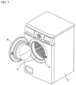
- FIG. 5 is a perspective view illustrating an exterior of a washing machine according to an embodiment of the present invention.
- FIG. 6 is a cross-sectional view illustrating an interior of a washing machine according to an embodiment of the present invention.
- FIG. 7 is a conceptual diagram in which a separate type induction heater module is mounted on a tub.
- a washing machine may include a tub 20 and a drum 30.
- the washing machine may further include a cabinet 10 forming an outer shape.
- the washing machine may further include an induction heater 70 provided to heat the drum 30.
- the tub 20 may be provided inside the cabinet 10.
- the tub 20 may provide an accommodation space.
- the tub 20 may have an opening in a forward direction.
- the tub 20 may accommodate washing water.
- the tub 20 may be provided to accommodate the drum 30.
- the drum 30 may be rotatably provided inside the tub 20.
- the drum 30 may be provided in the accommodation space of the tub 20.
- the drum 30 may accommodate laundry.
- An opening may be provided in a forward direction of the drum 30. Laundry may be loaded into the drum 30 through the opening.
- a through hole 30h may be formed in the circumferential surface of the drum 30 so that air and washing water are communicated between the tub 20 and the drum 30.
- the circumferential surface of the drum 30 may also be referred to as a body of the drum 30.
- the body of the drum 30 may extend in a cylindrical shape.
- the drum 30 may be made of a conductor.
- the body of the drum 30 may be made of a conductor.
- the body of the drum 30 may be made of metal.
- the induction heater or IH module 70 may heat the drum 30.
- the induction heater 70 may generate a magnetic field.
- the induction heater 70 may be provided to heat the drum 30 by using a magnetic field.
- the induction heater 70 may be provided on the outer circumferential surface of the tub 20.
- the induction heater 70 may be provided in the upper portion of the tub 20.
- the induction heater 70 may be fixed to the tub 20.
- the induction heater 70 may be spaced apart from the drum 30.
- the tub 20 and the drum 30 may be formed in a cylindrical shape.
- the inner and outer circumferential surfaces of the tub 20 and the drum 30 may be formed in a substantially cylindrical shape.
- a laundry treating apparatus such as a dryer may not include a tub.
- the induction heater 70 may be provided in the cabinet.
- the induction heater 70 may be disposed inside the cabinet or on an inner wall.
- the induction heater 70 may be spaced apart from the drum 30 and fixed to the cabinet 10.
- FIG. 6 shows a washing machine in which the drum 30 is rotated based on a rotation shaft parallel to a ground.
- the drum 30 and the tub 20 may have a tilting shape inclined in a rearward direction.
- the rotation shaft of the drum 30 may penetrate the rear surface of the washing machine. That is, a straight line extending from the rotation shaft 42 of a driving unit 40 may penetrate the rear surface of the washing machine.
- the washing machine may further include a driving unit 40 provided to rotate the drum 30 inside the tub 20.
- the driving unit 40 may include a motor 41.
- the motor 41 may include a rotation shaft 42.
- the rotation shaft 42 may be connected to the drum 30 to rotate the drum 30 inside the tub 20.
- the motor 41 may include a stator and a rotor.
- the rotor may be connected to the rotation shaft 42.
- the driving unit 40 may include a spider 43.
- the spider 43 is a configuration that connects the drum 30 and the rotation shaft 42, and may be a configuration for uniformly and stably transmitting the rotational force of the rotation shaft 42 to the drum 30.
- the spider 43 may be coupled to the drum 30 in such a manner that at least portion of the spider 43 is inserted into the rear wall of the drum 30.
- the rear wall of the drum 30 may be formed in such a manner that it is recessed to the inside of the drum 30.
- the spider 43 may be coupled to the drum 30 in such a manner that it is further inserted into the drum 30 at a portion of the center of rotation of the drum 30.
- a lifter 50 may be provided inside the drum 30.
- a plurality of lifters 50 may be provided along the circumferential direction of the drum 30.
- the lifter 50 may perform a function of agitating a laundry. For example, as the drum 30 rotates, the lifter 50 lifts a laundry to an upper portion.
- the laundry moved to the upper portion is separated from the lifter 50 by gravity and falls to a lower portion. Washing may be performed by an impact force caused by the falling of such laundry. Agitation of laundry can enhance drying efficiency.
- the lifter 50 may be formed by extending from a rear end of the drum 30 to a front end. Laundry may be evenly distributed back and forth inside the drum 30.
- the induction heater 70 is a device for heating the drum 30.
- the induction heater 70 may include a coil 71 that receives a current to generate a magnetic field.
- the coil 71 may generate an eddy current in the drum 30.
- the induction heater 70 may include a heater cover 72 accommodating the coil 71.
- a structure of the induction heater 70 and the principle of heating the drum 30 by the induction heater 70 will be omitted.
- the coil 71 heats the drum 30 to increase the temperature inside the drum 30 as well as the drum 30 itself.
- the induction heater 70 may heat the wash water in contact with the drum 30 through the heating of the drum 30.
- the induction heater 70 may heat the laundry in contact with the inner circumferential surface of the drum 30.
- the induction heater 70 may heat the laundry that is not in contact with the inner circumferential surface of the drum 30 by increasing the temperature inside the drum 30.
- the induction heater 70 may increase the washing effect by increasing the temperature of washing water, and laundry, and the ambient temperature inside the drum 30.
- the induction heater 70 may dry a laundry by increasing the laundry, the drum 30 and the ambient temperature inside the drum 30.
- FIG. 7 shows that the induction heater 70 is provided in the upper side of the tub 20, but it is not excluded that the induction heater 70 is provided on at least one surface of the upper side, lower side, and both sides of the tub 20.
- the induction heater 70 may be installed at a position higher than the maximum water level of the wash water stored in the tub 20.
- the induction heater 70 may be provided in one side of the outer circumferential surface of the tub 20, and the coil 71 may be provided to be wound at least once inside the cover 72 along a surface of the induction heater 70 adjacent to the tub 20.
- the induction heater 70 may generate an eddy current in the drum 30 by emitting an induced magnetic field directly to the outer circumferential surface of the drum 30, and as a result, may directly heat the outer circumferential surface of the drum 30.
- the laundry treating apparatus may include a controller (not shown, it may have the same configuration as a controller 85 of FIG. 8 ; hereinafter, it will be described using reference numeral 85) for controlling an output of the induction heater 70.
- the controller 85 may control an on/off and an output of the induction heater 70.
- the induction heater 70 may be connected to an external power supply source by an electric wire to receive power. Alternatively, the induction heater 70 may be connected to the controller 85 for controlling the operation of washing machine to receive power. The induction heater 70 may receive power from anywhere as long as it can supply power to the internal coil 71.
- the controller 85 may rotate the drum 30 through the motor 41 of the driving unit 40 when the induction heater 70 is operated.
- the controller 85 may cause the induction heater 70 to operate when the drum 30 rotates.
- the speed at which the motor 41 of the driving unit 40 rotates the drum 30 can safely be any speed.
- the laundry treating apparatus can evenly heat the outer circumferential surface of the drum 30, even if the induction heater 70 is not installed in places such as the upper side, the lower side, both sides of the outer circumferential surface of the tub 20, but is installed only in one place.
- the induction heater 70 can heat the drum 30 to a high temperature within a very short time.
- the induction heater 70 can heat the drum 30 to a target temperature within a very short time.
- the induction heater 70 can heat the drum 30 to 120 degrees Celsius or more within a very short time.
- the induction heater 70 When the induction heater 70 is driven in a state where the drum 30 is stopped or is at a very slow rotation speed, a specific portion of the drum 30 may be overheated very quickly. When the induction heater 70 is driven in a state where the drum 30 is stopped or is at a very slow rotation speed, heat may not be sufficiently transmitted from the heated drum 30 to the laundry.
- a correlation between the rotational speed of the drum 30 and the driving of the induction heater 70 may be very important. It may be more advantageous to rotate the drum 30 and drive the induction heater 70 than to drive the induction heater 70 and rotate the drum 30.
- FIG. 8 is a circuit diagram illustrating a circuit configuration of a washing machine according to an embodiment of the present invention.
- FIG. 9 is a schematic diagram illustrating an installation position of a circuit configuration of a washing machine according to an embodiment of the present invention.
- the laundry treating apparatus may include a first circuit 80 which is installed in the tub 20 and includes a first coil 82, a second coil 92 which is installed in the drum 30 and located to pass a point that interacts with the first coil 82 when the drum 30 rotates, and a second circuit 90 including a thermistor 91 whose resistance varies depending on temperature.
- the second coil may be installed in the drum 30, and may be located to pass a point within an area of the drum 30 overlapping to interact within a circumferential range of the first coil 82 and the drum 30 when the drum 30 rotates.
- the washing machine may include a controller MCU 85 which is connected to the first circuit 80 and estimates a temperature of the drum 30 by using a value related to the temperature of the drum 30 received by the interaction between the second coil 92 and the first coil 82.
- a laundry treating apparatus such as a dryer may not include a tub.
- the first circuit 80 may be disposed at a position capable of interacting with the second coil according to the rotational position of the drum on the inside or the inner wall of the cabinet 10.
- the first circuit 80 may further include a capacitor C connected in parallel with the first coil 82.
- the laundry treating apparatus may include a current detection unit 84 connected in series with the first coil 82 and a voltage detection unit 83 connected in parallel with the first coil 82.
- the thermistor 91 may be a Negative Temperature Coefficient-thermic resistor (NTC-thermistor) whose resistance decreases as the temperature increases.
- NTC-thermistor Negative Temperature Coefficient-thermic resistor
- the NTC-thermistor is also briefly referred to as an NTC.
- the resistance value of the NTC may be referred to as Rntc.
- the NTC may have a resistance value Rntc that exponentially decreases according to the temperature of a load (drum).
- the thermistor 91 and the NTC 91 will be described by using the same reference numeral.
- the second circuit 90 installed in the drum 30 may output at least one (hereinafter, it will be expressed as a voltage value and/or a current value) of a voltage value and a current value according to a resistance value that decreases according to the temperature of the NTC 91.
- the output voltage value and/or current value of the NTC 91 may be transmitted to the second coil 92. Thereafter, this value may be transmitted to the first circuit 80 by the interaction between the first coil 82 and the second coil 92. That is, a current that fluctuates according to a change in the resistance value of the NTC 91 can be transmitted to the first coil 82 of the first circuit 80 by the interaction between the first coil 82 and the second coil 92. In this case, the interaction may be an electromagnetic induction phenomenon in which current/voltage is induced between the first coil 82 and the second coil 92.
- the controller 85 may estimate a resistance value of the NTC 91 by using impedance obtained by detecting the voltage and current values obtained at this time.
- the controller 85 may estimate the temperature of the drum 30 from the estimated resistance value of the NTC 91.
- the controller 85 may compensate an error in the resistance value of the NTC 91 by comparing the impedance obtained by detecting the voltage and current values with an equivalent impedance of the first and second circuits 90 viewed from the capacitor. Through this, the error in the estimated temperature of the drum 30 can be compensated.
- a power supply unit 81 of the first circuit 80 may apply a resonant frequency. This resonant frequency may be the same as the frequency of a signal induced to the primary coil 82 through the secondary coil 92.
- Impedance can be defined as a ratio of AC voltage and current which are generated in a reference point or applied to a specific object.
- An alternating signal such as an AC voltage, has a phase.
- the capacitor C may increase the resolution (degree of change; degree of discrimination) of a value related to the temperature of the drum 30 received through the second coil 92.
- a distance between the first coil 82 and the second coil 92 may occur due to a structural distance between the drum 30 and the tub 20.
- the distance between the first coil 82 and the second coil 92 may be, for example, 28 mm to 30 mm. Accordingly, a mutual inductance M between the first coil 82 and the second coil 92 may be reduced.
- the capacitor C may compensate a phenomenon in which a change in the resistance value of the NTC 91 may not be significantly observed in the first circuit 80.
- the first coil 82 may be installed on the tub 20, in the opposite side of the coil 71 of the induction heater 70.
- the first coil 82 may be installed on the tub 20, in a range of ⁇ 60 degrees from the opposite side of the coil 71 of the induction heater 70.
- the first coil 82 may be installed in the tub 20.
- the first coil 82 may be located on the tub 20 in a direction opposite to the coil 71 of the induction heater 70. Accordingly, the influence of the magnetic field generated in the coil 71 of the induction heater 70 on the first coil 82 may be minimized.
- the first coil 82 may be installed within a range between positions of adjacent lifters indicated by dotted line in FIG. 9 . That is, the first coil 82 may be installed on the tub 20 in a range within ⁇ 60 degrees from the opposite side of the coil 71 of the induction heater 70. Accordingly, the influence of the magnetic field generated in the coil 71 of the induction heater 70 on the first coil 82 may be minimized. Thus, interference of the first coil 82 with other structure that may be provided under the tub 20 such as a washing heater other than the induction heater 70 can be avoided.
- the second coil 92 may be installed at a position passing the shortest distance from the first coil 82 according to the rotation of the drum 30. That is, when the drum 30 rotates, the second coil 92 installed in the drum 30 may pass a position of the shortest distance from the first coil 82.
- the second circuit 90 including the second coil 92 may be installed on the outer surface of the drum 30.
- the second circuit 90 including the NTC 91 and the second coil 92 in the outside of the drum 30 can be installed at the lifter position of the drum 30 that is a load.
- the dotted line in FIG. 9 indicates the position of the lifter.
- a balance maintaining unit 93 may be provided at a position that divides the circular angle of the drum 30 into equal parts with respect to a position where the second circuit 92 of the drum 30 is attached.
- a weight balance may be achieved by attaching the balance maintaining unit 93 made of a material having non-magnetic properties.
- a balance maintaining unit 93 may be installed in the other two parts.
- the balance maintaining unit 93 for maintaining a weight balance may not be installed.
- FIG. 10 is a schematic diagram illustrating an example of installation of a first coil and a second coil of a laundry treating apparatus according to an embodiment of the present invention.
- the size of the first coil 82 may be greater than the size of the second coil 92. That is, it may be advantageous that the size of the first coil 82 acting as a sensing coil is designed to be larger than the size of the second coil 92 transmitting a signal so as to maintain a constant inductance (L1, L2, M) value even during the rotation of the drum 30 in consideration of the rotation of the load (drum 30).
- L1, L2, M constant inductance
- the temperature error can be minimized by compensating an error by using rotation angle information of the drum 30.
- Equation 1 is a calculation expression representing the equivalent impedance Zeq viewed from the first circuit 80 (first side). More specifically, Equation 1 is a calculation expression representing the equivalent impedance Zeq of the first and second circuits 80 and 90 viewed from the capacitor C.
- the explanation in terms of the equivalent impedance Zeq of the first and second circuits 80 and 90 shown in FIG. 8 is as follows.
- Equation 1 L1 is an inductance of the first coil 82, L2 is an inductance of the second coil 92, and M is a mutual inductance.
- ⁇ represents a (resonant) frequency, and C represents a capacitance of the capacitor of the first circuit 80.
- Equation 1 the equivalent impedance Zeq of the first and second circuits 80 and 90 at a resonant frequency is briefly summarized as follows.
- the equivalent impedance Zeq of the first and second circuits 90 viewed from the capacitor C varies greatly according to a change in Rntc which is a resistance value of the NTC 91. That is, the equivalent impedance Zeq is proportional to the resistance Rntc of the NTC 91.
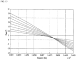
- FIG. 11 is a graph illustrating a relationship between an impedance phase angle and a frequency.
- FIG. 12 is a graph illustrating a relationship between an impedance magnitude and a frequency.
- the impedance phase angle is changed to specify a frequency to be measured.
- the temperature may be estimated by measuring the magnitude of the impedance at the frequency specified above.
- the magnitude of the impedance changes 100 times from 200 ⁇ to 20 k ⁇ , which may mean that the discrimination power for temperature estimation is sufficient.
- FIG. 13 is a graph illustrating a relationship between an impedance phase angle and a frequency under a simulation condition.
- FIG. 14 is a graph illustrating a relationship between an impedance magnitude and a frequency under a simulation condition.
- FIG. 15 is a graph illustrating a change in a resistance value according to a temperature of NTC.
- the first side coil turn ratio of the first coil 82 and the second coil 92 is 5 to 5 (5:5), and a distance between the first circuit 80 and the second circuit 90 is 30mm.
- Equation 2 is summarized as follows.
- the Rntc value of the NTC 91 may be derived by using the phase of the equivalent impedance Zeq and the impedance magnitude at a specific frequency.
- the Rntc value of the NTC 91 varies from 200 to 1000 ⁇ , and at this time, the temperature of the NTC varies from 100 to 150°C.
- the temperature of the drum 30 can be estimated with a sufficient accuracy by using a circuit shown in FIG. 8 .
- accurate temperature estimation may be possible by using the characteristic of the NTC resistance that exponentially decreases depending on temperature.
- the influence on the inductance/capacitance distribution may be small.
- FIG. 16 is a flowchart illustrating a method of controlling a laundry treating apparatus.
- the temperature of the drum 30 of the washing machine may be estimated by using the circuit as described with reference to FIG. 8 .
- the resistance value of the NTC 91 and the temperature of the drum 30 can be estimated by comparing the impedance obtained by detecting the voltage and current values received from the second coil 92 with the equivalent impedance of the first and second circuits 80 and 90 viewed from the first circuit 80.
- a step S10 of driving the laundry treating apparatus may be performed.
- the laundry treating apparatus may correspond to a washing machine, a dryer, and a washing machine (dryer-integrated washing machine) which is integrated with a dryer.
- a washing machine dryer-integrated washing machine
- a washing machine will be described as a representative example.
- the laundry treating apparatus of the present invention is not limited thereto.
- the step S10 of driving the laundry treating apparatus may include a process S11 of heating and rotating the load (drum 30).
- the step S10 of driving the laundry treating apparatus may include a process S12 of applying a resonance frequency to the power supply unit 81 of the first circuit (first side 80).
- the step S10 of driving the laundry treating apparatus may include the process of aligning the first coil 82 (primary coil) and the second coil 92 (secondary coil).
- the process of aligning the first coil 82 (primary coil) and the second coil 92 (secondary coil) may be performed automatically or manually in the washing machine.
- the process of aligning the first coil 82 (primary coil) and the second coil 92 (secondary coil) may be omitted.
- a process S11 of heating and rotating the load (drum 30) may be performed after such an alignment process.
- the second circuit 90 may include the thermistor 91.
- the thermistor 91 may be an NTC thermistor 91.
- the resistance of the NTC 91 may be changed by heating the drum 30. Such a change in resistance may follow the graph shown in FIG. 15 . The change in a curve in this graph may vary according to the NTC 91.
- the output current (and/or voltage) of the NTC 91 may be transmitted to the first coil 82 through the second coil 92 (S21). That is, the output current (and/or voltage) by Rntc, which is the resistance value of the NTC 91 in the second side, may be transmitted to the first coil 82.
- the current (and/or voltage) reflecting Rntc may be detected (S22).
- a step S30 of calculating the equivalent impedance of the first and second circuits 80 may be performed by using the current (and/or voltage) value reflecting the detected Rntc.
- the step S30 of calculating the equivalent impedance may include a process of determining the magnitude and phase angle of the equivalent impedance Zeq.
- impedance can be defined as the ratio of AC voltage and current which are generated in a reference point or applied to a specific object.
- An alternating signal such as an AC voltage, has a phase.
- steps (S40, S41) of matching the impedance measured by an output value of the second circuit 90 with the resonance frequency of the equivalent impedance Zeq may be performed.
- the steps (S40, S41) of matching the resonance frequency may include a step S40 of comparing the impedance measured by an output value of the second circuit 90 with the resonance frequency of the equivalent impedance Zeq to obtain an error, and a step S41 of compensating an error in the inductance value of the first coil 82.
- the error value may include a capacitance value C.
- an applied frequency applied to the power supply unit 81 of the first side 80 may be changed according to the compensated error value.
- steps (S50, S51) of matching the impedance measured by the output value of the second circuit 90 with the phase angle of the equivalent impedance Zeq may be performed.
- steps (S50, S51) of matching the phase angle may include a step S50 of comparing the impedance measured by the output value of the second circuit 90 and the phase angle of the equivalent impedance Zeq to obtain an error, and a step S51 of compensating the error of phase angle by using the rotation angle of the drum 30.
- a step S60 of estimating the temperature of the drum 30 through the thermistor NTC 91 with the magnitude of the equivalent impedance Zeq can be performed.
- the compensation of the error using the rotation angle of the load (drum 30) may be applied to the step S60 of estimating the temperature of the drum 30 through the thermistor (NTC) 91 with the magnitude of the equivalent impedance Zeq.
Landscapes
- Engineering & Computer Science (AREA)
- Textile Engineering (AREA)
- Physics & Mathematics (AREA)
- Electromagnetism (AREA)
- Control Of Washing Machine And Dryer (AREA)
Claims (15)
- Wäschebehandlungsvorrichtung, die Folgendes umfasst:einen Bottich (20);eine Trommel (30), die im Bottich (20) drehbar bereitgestellt ist;eine Induktionsheizeinrichtung (70), die am Bottich (20) befestigt ist, wobei sie von der Trommel (30) beabstandet ist, und die die Trommel (30) heizt;gekennzeichnet durcheine erste Schaltung (80), die eine erste Spule (82) umfasst, die im Bottich (20) installiert ist;eine Leistungsversorgungseinheit (81), die der ersten Spule (82) Wechselspannungsleistung zuführt; undeine zweite Schaltung (90), die in der Trommel (30) installiert ist, wobei die zweite Schaltung (90) eine zweite Spule (92), die an einer Position angeordnet ist, die in einer Längsrichtung einer zentralen drehbaren Welle der Trommel (30) mit der ersten Spule (82) überlappt, und einen Thermistor (91), dessen Widerstand sich in Abhängigkeit von der Temperatur ändert, umfasst.
- Wäschebehandlungsvorrichtung nach Anspruch 1, wobei der Thermistor (91) einen NTC-Thermistor umfasst, dessen Widerstand abnimmt, wenn die Temperatur ansteigt.
- Wäschebehandlungsvorrichtung nach Anspruch 1, wobei die zweite Spule (92) an einer Position installiert ist, an der eine gerade Linie, die an der ersten Spule (82) vorbei und senkrecht zu einer Drehzentrumslinie der Trommel (30) verläuft, auf die Trommel (30) trifft.
- Wäschebehandlungsvorrichtung nach Anspruch 1, wobei die zweite Schaltung (90) an einer Außenfläche der Trommel (30) installiert ist.
- Wäschebehandlungsvorrichtung nach Anspruch 4, die ferner eine Hebevorrichtung (50) umfasst, die an einer Innenfläche der Trommel (30) bereitgestellt ist,
wobei die zweite Schaltung (90) an einer Außenfläche eines Abschnitts der Trommel (30) installiert ist, in dem die Hebevorrichtung (50) angeordnet ist. - Wäschebehandlungsvorrichtung nach Anspruch 5, wobei die Trommel (30) Folgendes umfasst:einen Körper, der die Form eines länglichen Zylinders hat; undein Durchgangsloch (30h), das im Körper ausgebildet ist.
- Wäschebehandlungsvorrichtung nach Anspruch 5, wobei die Hebevorrichtung (50) mehrere Hebevorrichtungen (50) umfasst, die in regelmäßigen Abständen längs einer Umfangsrichtung der Trommel (30) angeordnet sind,wobei die zweite Schaltung (90) an einer Außenfläche eines Abschnitts der Trommel (30) installiert ist, in dem eine Hebevorrichtung (50) der mehreren Hebevorrichtungen (50) angeordnet ist,wobei die Wäschebehandlungsvorrichtung ferner eine nicht magnetische Einheit (93) zur Aufrechterhaltung eines Gleichgewichts umfasst, die innerhalb der verbleibenden Hebevorrichtungen (50) der mehreren Hebevorrichtungen (50) bereitgestellt ist.
- Wäschebehandlungsvorrichtung nach Anspruch 1, die ferner eine oder mehrere nicht magnetische Einheiten (93) zur Aufrechterhaltung eines Gleichgewichts umfasst, die angrenzend an die Trommel (30) vorgesehen sind,
wobei die zweite Schaltung (90) und die eine oder die mehreren Einheiten (93) zur Aufrechterhaltung eines Gleichgewichts in regelmäßigen Abständen längs einer Umfangsrichtung der Trommel (30) angeordnet sind. - Wäschebehandlungsvorrichtung nach Anspruch 1, wobei die erste Spule (82) auf einer gegenüberliegenden Seite der Induktionsheizeinrichtung (70) in Bezug auf das Zentrum des Bottichs (20) installiert ist.
- Wäschebehandlungsvorrichtung nach Anspruch 9, wobei die erste Spule (82) im Bereich von ±60 Grad von einem Punkt gegenüber der Induktionsheizeinrichtung (70) in Bezug auf das Zentrum des Bottichs (20) installiert ist.
- Wäschebehandlungsvorrichtung nach Anspruch 1, wobei die erste Spule (82) längs einer Umfangsrichtung der Trommel (30) einen Bereich belegt, der größer als ein Bereich ist, der durch die zweite Spule (92) belegt ist.
- Wäschebehandlungsvorrichtung nach Anspruch 1, wobei die erste Schaltung (80) ferner einen Kondensator (C) umfasst, der zur ersten Spule (82) parallel geschaltet ist.
- Wäschebehandlungsvorrichtung nach Anspruch 1, die ferner eine Steuereinheit (85) umfasst, die mit der ersten Schaltung (80) verbunden ist und eine Temperatur der Trommel (30) auf der Basis eines Widerstandswerts des Thermistors (91) schätzt.
- Wäschebehandlungsvorrichtung nach Anspruch 13, die ferner Folgendes umfasst:eine Stromdetektionseinheit (84), die mit der ersten Spule (82) in Reihe geschaltet ist; undeine Spannungsdetektionseinheit (83), die zur ersten Spule (82) parallel geschaltet ist.
- Wäschebehandlungsvorrichtung nach Anspruch 14, wobei die Steuereinheit (85) die Temperatur der Trommel (30) auf der Basis einer gemessenen Impedanz schätzt, die als ein Wert definiert ist, der durch Dividieren eines Spannungswerts, der durch die Spannungsdetektionseinheit (83) detektiert wird, durch einen Stromwert, der durch die Stromdetektionseinheit (84) detektiert wird, erhalten wird.
Applications Claiming Priority (2)
| Application Number | Priority Date | Filing Date | Title |
|---|---|---|---|
| KR20200025604 | 2020-02-28 | ||
| PCT/KR2021/002515 WO2021172959A1 (ko) | 2020-02-28 | 2021-02-26 | 의류처리장치 |
Publications (3)
| Publication Number | Publication Date |
|---|---|
| EP4112802A1 EP4112802A1 (de) | 2023-01-04 |
| EP4112802A4 EP4112802A4 (de) | 2024-02-28 |
| EP4112802B1 true EP4112802B1 (de) | 2025-01-29 |
Family
ID=77797200
Family Applications (1)
| Application Number | Title | Priority Date | Filing Date |
|---|---|---|---|
| EP21759901.8A Active EP4112802B1 (de) | 2020-02-28 | 2021-02-26 | Vorrichtung zur behandlung von kleidung |
Country Status (2)
| Country | Link |
|---|---|
| EP (1) | EP4112802B1 (de) |
| KR (1) | KR102899398B1 (de) |
Family Cites Families (7)
| Publication number | Priority date | Publication date | Assignee | Title |
|---|---|---|---|---|
| JP2580257Y2 (ja) * | 1992-12-01 | 1998-09-03 | 象印マホービン株式会社 | 回転式電磁誘導加熱調理器 |
| KR100424315B1 (ko) * | 2002-01-09 | 2004-03-25 | 엘지전자 주식회사 | 드럼세탁기의 터브 |
| ATE460525T1 (de) * | 2006-10-19 | 2010-03-15 | Electrolux Home Prod Corp | Haushaltwaschmaschine mit induktiver heizung |
| PL2100996T3 (pl) * | 2008-03-11 | 2016-06-30 | Whirlpool Co | Urządzenie myjące z grzaniem indukcyjnym |
| DE102016122744A1 (de) | 2016-11-25 | 2018-05-30 | Miele & Cie. Kg | Verfahren und Ansteuerschaltung für einen induktionsbeheizten Wäschetrockner |
| KR102526715B1 (ko) * | 2018-02-23 | 2023-04-28 | 엘지전자 주식회사 | 세탁기 |
| KR102525026B1 (ko) * | 2018-02-23 | 2023-04-24 | 엘지전자 주식회사 | 세탁기 및 세탁기의 제어방법 |
-
2021
- 2021-02-26 KR KR1020210026714A patent/KR102899398B1/ko active Active
- 2021-02-26 EP EP21759901.8A patent/EP4112802B1/de active Active
Also Published As
| Publication number | Publication date |
|---|---|
| KR102899398B1 (ko) | 2025-12-15 |
| EP4112802A4 (de) | 2024-02-28 |
| EP4112802A1 (de) | 2023-01-04 |
| KR20210110231A (ko) | 2021-09-07 |
Similar Documents
| Publication | Publication Date | Title |
|---|---|---|
| US11840789B2 (en) | Washing machine and control method of washing machine | |
| US11050297B2 (en) | Laundry treating apparatus | |
| EP2013405B1 (de) | Wäschetrockner und betriebsverfahren dafür | |
| KR102588467B1 (ko) | 세탁물 건조기 | |
| US10067003B2 (en) | Method and device for determining a surface temperature of an inductively heated roller shell | |
| EP4112802B1 (de) | Vorrichtung zur behandlung von kleidung | |
| JP2017127402A (ja) | 衣類乾燥機 | |
| US20230102943A1 (en) | Laundry treating apparatus | |
| KR101611270B1 (ko) | 무게감지장치를 갖는 건조기 및 이를 이용한 건조기제어방법 | |
| EP4123076B1 (de) | Vorrichtung zur behandlung von kleidungsstücken | |
| US12173444B2 (en) | Clothes treatment apparatus | |
| CN118360768A (zh) | 一种衣物处理设备 | |
| EP2610388A1 (de) | Wäschetrockner und Steuerverfahren dafür | |
| JP2009100794A (ja) | 洗濯機 | |
| JP5104671B2 (ja) | 洗濯機 | |
| JP5104670B2 (ja) | 洗濯機 | |
| EP4703510A1 (de) | Haushaltsgerät mit effizienter trocknung und zugehöriges steuerungsverfahren | |
| JP5104672B2 (ja) | 洗濯機 | |
| EP2058927A2 (de) | Maschine zur Behandlung von Textilartikeln | |
| US9267225B2 (en) | Method of estimating bending moment of a laundry treating appliance drum shaft using a proximity sensor | |
| JP2023554431A (ja) | 固定部と可動部との間の非接触電力伝送のための方法、電力供給回路、および電力供給回路を含む非接触接続システム |
Legal Events
| Date | Code | Title | Description |
|---|---|---|---|
| STAA | Information on the status of an ep patent application or granted ep patent |
Free format text: STATUS: THE INTERNATIONAL PUBLICATION HAS BEEN MADE |
|
| PUAI | Public reference made under article 153(3) epc to a published international application that has entered the european phase |
Free format text: ORIGINAL CODE: 0009012 |
|
| STAA | Information on the status of an ep patent application or granted ep patent |
Free format text: STATUS: REQUEST FOR EXAMINATION WAS MADE |
|
| 17P | Request for examination filed |
Effective date: 20220928 |
|
| AK | Designated contracting states |
Kind code of ref document: A1 Designated state(s): AL AT BE BG CH CY CZ DE DK EE ES FI FR GB GR HR HU IE IS IT LI LT LU LV MC MK MT NL NO PL PT RO RS SE SI SK SM TR |
|
| DAV | Request for validation of the european patent (deleted) | ||
| DAX | Request for extension of the european patent (deleted) | ||
| A4 | Supplementary search report drawn up and despatched |
Effective date: 20240131 |
|
| RIC1 | Information provided on ipc code assigned before grant |
Ipc: H05B 6/10 20060101ALI20240125BHEP Ipc: D06F 34/10 20200101ALI20240125BHEP Ipc: D06F 34/26 20200101ALI20240125BHEP Ipc: D06F 58/40 20200101ALI20240125BHEP Ipc: D06F 58/26 20060101ALI20240125BHEP Ipc: D06F 39/04 20060101AFI20240125BHEP |
|
| GRAP | Despatch of communication of intention to grant a patent |
Free format text: ORIGINAL CODE: EPIDOSNIGR1 |
|
| STAA | Information on the status of an ep patent application or granted ep patent |
Free format text: STATUS: GRANT OF PATENT IS INTENDED |
|
| INTG | Intention to grant announced |
Effective date: 20240925 |
|
| GRAS | Grant fee paid |
Free format text: ORIGINAL CODE: EPIDOSNIGR3 |
|
| GRAA | (expected) grant |
Free format text: ORIGINAL CODE: 0009210 |
|
| STAA | Information on the status of an ep patent application or granted ep patent |
Free format text: STATUS: THE PATENT HAS BEEN GRANTED |
|
| AK | Designated contracting states |
Kind code of ref document: B1 Designated state(s): AL AT BE BG CH CY CZ DE DK EE ES FI FR GB GR HR HU IE IS IT LI LT LU LV MC MK MT NL NO PL PT RO RS SE SI SK SM TR |
|
| REG | Reference to a national code |
Ref country code: GB Ref legal event code: FG4D |
|
| REG | Reference to a national code |
Ref country code: CH Ref legal event code: EP |
|
| REG | Reference to a national code |
Ref country code: DE Ref legal event code: R096 Ref document number: 602021025462 Country of ref document: DE |
|
| REG | Reference to a national code |
Ref country code: IE Ref legal event code: FG4D |
|
| PGFP | Annual fee paid to national office [announced via postgrant information from national office to epo] |
Ref country code: AT Payment date: 20250417 Year of fee payment: 5 |
|
| REG | Reference to a national code |
Ref country code: NL Ref legal event code: MP Effective date: 20250129 |
|
| PG25 | Lapsed in a contracting state [announced via postgrant information from national office to epo] |
Ref country code: NL Free format text: LAPSE BECAUSE OF FAILURE TO SUBMIT A TRANSLATION OF THE DESCRIPTION OR TO PAY THE FEE WITHIN THE PRESCRIBED TIME-LIMIT Effective date: 20250129 |
|
| PG25 | Lapsed in a contracting state [announced via postgrant information from national office to epo] |
Ref country code: RS Free format text: LAPSE BECAUSE OF FAILURE TO SUBMIT A TRANSLATION OF THE DESCRIPTION OR TO PAY THE FEE WITHIN THE PRESCRIBED TIME-LIMIT Effective date: 20250429 |
|
| PG25 | Lapsed in a contracting state [announced via postgrant information from national office to epo] |
Ref country code: FI Free format text: LAPSE BECAUSE OF FAILURE TO SUBMIT A TRANSLATION OF THE DESCRIPTION OR TO PAY THE FEE WITHIN THE PRESCRIBED TIME-LIMIT Effective date: 20250129 |
|
| PG25 | Lapsed in a contracting state [announced via postgrant information from national office to epo] |
Ref country code: PL Free format text: LAPSE BECAUSE OF FAILURE TO SUBMIT A TRANSLATION OF THE DESCRIPTION OR TO PAY THE FEE WITHIN THE PRESCRIBED TIME-LIMIT Effective date: 20250129 |
|
| PG25 | Lapsed in a contracting state [announced via postgrant information from national office to epo] |
Ref country code: ES Free format text: LAPSE BECAUSE OF FAILURE TO SUBMIT A TRANSLATION OF THE DESCRIPTION OR TO PAY THE FEE WITHIN THE PRESCRIBED TIME-LIMIT Effective date: 20250129 |
|
| REG | Reference to a national code |
Ref country code: LT Ref legal event code: MG9D |
|
| PG25 | Lapsed in a contracting state [announced via postgrant information from national office to epo] |
Ref country code: NO Free format text: LAPSE BECAUSE OF FAILURE TO SUBMIT A TRANSLATION OF THE DESCRIPTION OR TO PAY THE FEE WITHIN THE PRESCRIBED TIME-LIMIT Effective date: 20250429 Ref country code: IS Free format text: LAPSE BECAUSE OF FAILURE TO SUBMIT A TRANSLATION OF THE DESCRIPTION OR TO PAY THE FEE WITHIN THE PRESCRIBED TIME-LIMIT Effective date: 20250529 |
|
| REG | Reference to a national code |
Ref country code: AT Ref legal event code: MK05 Ref document number: 1763532 Country of ref document: AT Kind code of ref document: T Effective date: 20250129 |
|
| PG25 | Lapsed in a contracting state [announced via postgrant information from national office to epo] |
Ref country code: HR Free format text: LAPSE BECAUSE OF FAILURE TO SUBMIT A TRANSLATION OF THE DESCRIPTION OR TO PAY THE FEE WITHIN THE PRESCRIBED TIME-LIMIT Effective date: 20250129 |
|
| PG25 | Lapsed in a contracting state [announced via postgrant information from national office to epo] |
Ref country code: LV Free format text: LAPSE BECAUSE OF FAILURE TO SUBMIT A TRANSLATION OF THE DESCRIPTION OR TO PAY THE FEE WITHIN THE PRESCRIBED TIME-LIMIT Effective date: 20250129 Ref country code: PT Free format text: LAPSE BECAUSE OF FAILURE TO SUBMIT A TRANSLATION OF THE DESCRIPTION OR TO PAY THE FEE WITHIN THE PRESCRIBED TIME-LIMIT Effective date: 20250529 |
|
| PG25 | Lapsed in a contracting state [announced via postgrant information from national office to epo] |
Ref country code: GR Free format text: LAPSE BECAUSE OF FAILURE TO SUBMIT A TRANSLATION OF THE DESCRIPTION OR TO PAY THE FEE WITHIN THE PRESCRIBED TIME-LIMIT Effective date: 20250430 Ref country code: BG Free format text: LAPSE BECAUSE OF FAILURE TO SUBMIT A TRANSLATION OF THE DESCRIPTION OR TO PAY THE FEE WITHIN THE PRESCRIBED TIME-LIMIT Effective date: 20250129 |
|
| PG25 | Lapsed in a contracting state [announced via postgrant information from national office to epo] |
Ref country code: AT Free format text: LAPSE BECAUSE OF FAILURE TO SUBMIT A TRANSLATION OF THE DESCRIPTION OR TO PAY THE FEE WITHIN THE PRESCRIBED TIME-LIMIT Effective date: 20250129 |
|
| PG25 | Lapsed in a contracting state [announced via postgrant information from national office to epo] |
Ref country code: SE Free format text: LAPSE BECAUSE OF FAILURE TO SUBMIT A TRANSLATION OF THE DESCRIPTION OR TO PAY THE FEE WITHIN THE PRESCRIBED TIME-LIMIT Effective date: 20250129 |
|
| REG | Reference to a national code |
Ref country code: CH Ref legal event code: PL |
|
| PG25 | Lapsed in a contracting state [announced via postgrant information from national office to epo] |
Ref country code: SM Free format text: LAPSE BECAUSE OF FAILURE TO SUBMIT A TRANSLATION OF THE DESCRIPTION OR TO PAY THE FEE WITHIN THE PRESCRIBED TIME-LIMIT Effective date: 20250129 |
|
| PG25 | Lapsed in a contracting state [announced via postgrant information from national office to epo] |
Ref country code: DK Free format text: LAPSE BECAUSE OF FAILURE TO SUBMIT A TRANSLATION OF THE DESCRIPTION OR TO PAY THE FEE WITHIN THE PRESCRIBED TIME-LIMIT Effective date: 20250129 |
|
| PG25 | Lapsed in a contracting state [announced via postgrant information from national office to epo] |
Ref country code: MC Free format text: LAPSE BECAUSE OF FAILURE TO SUBMIT A TRANSLATION OF THE DESCRIPTION OR TO PAY THE FEE WITHIN THE PRESCRIBED TIME-LIMIT Effective date: 20250129 |
|
| PG25 | Lapsed in a contracting state [announced via postgrant information from national office to epo] |
Ref country code: IT Free format text: LAPSE BECAUSE OF FAILURE TO SUBMIT A TRANSLATION OF THE DESCRIPTION OR TO PAY THE FEE WITHIN THE PRESCRIBED TIME-LIMIT Effective date: 20250129 Ref country code: LU Free format text: LAPSE BECAUSE OF NON-PAYMENT OF DUE FEES Effective date: 20250226 |
|
| PG25 | Lapsed in a contracting state [announced via postgrant information from national office to epo] |
Ref country code: CH Free format text: LAPSE BECAUSE OF NON-PAYMENT OF DUE FEES Effective date: 20250228 |
|
| PG25 | Lapsed in a contracting state [announced via postgrant information from national office to epo] |
Ref country code: CZ Free format text: LAPSE BECAUSE OF FAILURE TO SUBMIT A TRANSLATION OF THE DESCRIPTION OR TO PAY THE FEE WITHIN THE PRESCRIBED TIME-LIMIT Effective date: 20250129 Ref country code: EE Free format text: LAPSE BECAUSE OF FAILURE TO SUBMIT A TRANSLATION OF THE DESCRIPTION OR TO PAY THE FEE WITHIN THE PRESCRIBED TIME-LIMIT Effective date: 20250129 |
|
| PG25 | Lapsed in a contracting state [announced via postgrant information from national office to epo] |
Ref country code: RO Free format text: LAPSE BECAUSE OF FAILURE TO SUBMIT A TRANSLATION OF THE DESCRIPTION OR TO PAY THE FEE WITHIN THE PRESCRIBED TIME-LIMIT Effective date: 20250129 |
|
| PG25 | Lapsed in a contracting state [announced via postgrant information from national office to epo] |
Ref country code: SK Free format text: LAPSE BECAUSE OF FAILURE TO SUBMIT A TRANSLATION OF THE DESCRIPTION OR TO PAY THE FEE WITHIN THE PRESCRIBED TIME-LIMIT Effective date: 20250129 |
|
| REG | Reference to a national code |
Ref country code: DE Ref legal event code: R097 Ref document number: 602021025462 Country of ref document: DE |
|
| PLBE | No opposition filed within time limit |
Free format text: ORIGINAL CODE: 0009261 |
|
| STAA | Information on the status of an ep patent application or granted ep patent |
Free format text: STATUS: NO OPPOSITION FILED WITHIN TIME LIMIT |
|
| REG | Reference to a national code |
Ref country code: BE Ref legal event code: MM Effective date: 20250228 |
|
| GBPC | Gb: european patent ceased through non-payment of renewal fee |
Effective date: 20250429 |
|
| 26N | No opposition filed |
Effective date: 20251030 |
|
| PG25 | Lapsed in a contracting state [announced via postgrant information from national office to epo] |
Ref country code: GB Free format text: LAPSE BECAUSE OF NON-PAYMENT OF DUE FEES Effective date: 20250429 |
|
| PG25 | Lapsed in a contracting state [announced via postgrant information from national office to epo] |
Ref country code: FR Free format text: LAPSE BECAUSE OF NON-PAYMENT OF DUE FEES Effective date: 20250329 |
|
| PG25 | Lapsed in a contracting state [announced via postgrant information from national office to epo] |
Ref country code: BE Free format text: LAPSE BECAUSE OF NON-PAYMENT OF DUE FEES Effective date: 20250228 |
|
| PG25 | Lapsed in a contracting state [announced via postgrant information from national office to epo] |
Ref country code: IE Free format text: LAPSE BECAUSE OF NON-PAYMENT OF DUE FEES Effective date: 20250226 |
|
| PGFP | Annual fee paid to national office [announced via postgrant information from national office to epo] |
Ref country code: DE Payment date: 20260105 Year of fee payment: 6 |