EP4112792B1 - Rapier wheel - Google Patents
Rapier wheel Download PDFInfo
- Publication number
- EP4112792B1 EP4112792B1 EP21182508.8A EP21182508A EP4112792B1 EP 4112792 B1 EP4112792 B1 EP 4112792B1 EP 21182508 A EP21182508 A EP 21182508A EP 4112792 B1 EP4112792 B1 EP 4112792B1
- Authority
- EP
- European Patent Office
- Prior art keywords
- spokes
- spoke
- outer ring
- rapier
- pairs
- Prior art date
- Legal status (The legal status is an assumption and is not a legal conclusion. Google has not performed a legal analysis and makes no representation as to the accuracy of the status listed.)
- Active
Links
Images



Classifications
-
- D—TEXTILES; PAPER
- D03—WEAVING
- D03D—WOVEN FABRICS; METHODS OF WEAVING; LOOMS
- D03D47/00—Looms in which bulk supply of weft does not pass through shed, e.g. shuttleless looms, gripper shuttle looms, dummy shuttle looms
- D03D47/27—Drive or guide mechanisms for weft inserting
- D03D47/275—Drive mechanisms
- D03D47/276—Details or arrangement of sprocket wheels
-
- F—MECHANICAL ENGINEERING; LIGHTING; HEATING; WEAPONS; BLASTING
- F16—ENGINEERING ELEMENTS AND UNITS; GENERAL MEASURES FOR PRODUCING AND MAINTAINING EFFECTIVE FUNCTIONING OF MACHINES OR INSTALLATIONS; THERMAL INSULATION IN GENERAL
- F16H—GEARING
- F16H55/00—Elements with teeth or friction surfaces for conveying motion; Worms, pulleys or sheaves for gearing mechanisms
- F16H55/02—Toothed members; Worms
- F16H55/30—Chain-wheels
Definitions
- the invention relates to a rapier wheel for a rapier weaving machine and to a rapier weaving machine with such a rapier wheel.
- a gripper is attached at the front end of a rapier for moving the gripper through a shed.
- the rapier is driven by a rapier wheel arranged next to the shed.
- the rapier can be a flexible gripper band or a more rigid gripper rod.
- a rapier wheel is shown for example in EP 3 262 222 B1 , wherein the rapier wheel has a number of spokes, which are arranged in pairs, wherein each pair of spokes comprises two crosswise arranged straight spokes.
- a rapier wheel for a rapier weaving machine having an inner ring, an outer ring, and a number spokes, wherein the inner ring is configured and adapted for mounting the inner ring to a drive shaft, wherein the outer ring is provided with teeth configured and adapted for engaging with a rapier for driving the rapier, wherein the spokes extend between the inner ring and the outer ring and connect the inner ring with the outer ring, wherein the spokes are arranged crosswise in pairs of spokes comprising a first spoke and a second spoke, wherein the first spoke and the second spoke extend in opposite directions and cross each other at a crossing point between the inner ring and the outer ring, and wherein the first spoke and the second spoke are each convexly curved toward the outer ring.
- the first spokes and the second spokes are each convexly curved toward the outer ring.
- curved spokes that extend either entirely or in portion along a path which seen in an outward radial direction of the associated pair of spokes is above a virtual straight line connecting ends of the spokes at the inner ring and the outer ring, are referred to as "convexly curved toward the outer ring".
- the crossing point of the first spoke and the second spoke is closer to the outer ring than a crossing point of two virtual straight lines crossing each other, wherein each virtual straight line connects an end point of a spoke of a pair of spokes at the inner ring and an end point of this spoke at the outer ring.
- the first spokes and the second spokes are also conjointly referred to as spokes.
- the spokes are provided in pairs, wherein the two spokes of each pair are curved in opposite directions.
- the spokes curved in opposite directions allow to counter forces regardless of a direction of rotation of the rapier wheel.
- the first spoke for example is curved in a clockwise direction, i.e., its end point at the outer ring is angularly offset in a clockwise direction from its endpoint at the inner ring.
- the second spoke is curved in a counterclockwise direction, i.e., its end point at the outer ring is angularly offset in a counterclockwise direction from its end point at the inner ring.
- the expressions first and second in this context are only intended to distinguish the spokes from each other and not to indicate any relevance or order of the spokes.
- the shape of the spokes is chosen, such that the first spoke of each pair of spokes does not cross any other first spoke, and the second spoke of each pair of spokes does not cross any other second spoke.
- the rapier wheel is manufactured for example by injection molding, milling, waterjet cutting or punching.
- each spoke has a constant radius of curvature, wherein the radius of curvature is the same for all spokes.
- a curvature of each of the spokes starts at a center of the rapier wheel and increases towards the outer ring.
- the spokes are spirally curved.
- the curvature increases continuously towards the outer ring.
- the spokes extend between an outer edge of the inner ring and an inner edge of the outer ring.
- a curvature of the spokes starts at an imaginary line at the center of the rapier wheel.
- the expression "starts at a center” is not to be interpreted in such way that the imaginary line has its center of origin at the center of the rapier wheel.
- the curvature is chosen such that the curvature asymptotically approaches the center of the rapier wheel.
- spokes that differ in shape are provided.
- the first spokes and the second spokes have a same shape, wherein the first spoke and the second spoke of each pair of spokes are arranged symmetrically to a radial direction through the crossing point of this pair of spokes.
- the crossing points of all pairs of spokes are arranged on a first imaginary circle.
- the spokes are also curved in a direction of an axis of rotation of the rapier wheel.
- the first spokes and the second spokes are arranged in two parallel planes, wherein in one embodiment the spokes of each pair are connected to each other at the crossing points.
- the rapier wheel is flat, wherein the first spokes and the second spokes are arranged in a common plane.
- the pairs of spokes are evenly distributed about the rapier wheel.
- the first spoke of each pair of spokes does only cross the second spoke of the associated pair of spokes, or in addition crosses one or more second spokes of other pairs of spokes.
- the crossing points of the pairs of spokes are arranged on a first imaginary circle, wherein the first spokes and the second spokes of two immediately neighboring pairs of spokes cross at second crossing points, wherein the second crossing points are arranged on a second imaginary circle having a smaller radius than the first imaginary circle.
- pairs of spokes that are successively arranged along the circumference of the outer ring are referred to as immediately neighboring pairs of spokes.
- the second imaginary circle is at a region of the inner ring, wherein connecting areas are formed between the inner ring and the first spokes and the second spokes of the two pairs of spokes.
- each first spoke crosses the second spokes of two or more pairs of spokes. In case the first spokes cross the second spokes of more than one other pair of spokes, an imaginary circle of the crossing points decreases with the distance between the pairs of spokes at the outer ring.
- an imaginary circle of crossing points between the first spoke and the second spoke furthest away from the first spoke in a circumferential direction of the rapier wheel, but still crossing the first spoke is at a region of the inner ring, wherein connecting areas are formed between the inner ring and the first spokes and the second spokes of the two associated pairs of spokes.
- the connecting areas at the inner ring in particular embodiments are closed.
- area ... is closed is used to describe that the area is filled with material.
- supporting rods are provided that extend between the crossing points of the pairs of spokes and the outer ring.
- the supporting rods extend in the radial direction of the pair of spokes to provide an additional support of the outer ring.
- straight supporting rods are provided.
- the supporting rods are arranged centered between the first spokes and the second spokes. Hence, in a circumferential direction of the outer ring a distance between the first spoke and the supporting rod of each pair of spokes is the same as a distance between the second spoke and the supporting rod of said pair of spokes.
- Y-shaped supporting rods are provided.
- straight supporting rods are provided that extend in radial direction between the crossing point of each pair of spokes and the outer ring.
- the pairs of spokes are evenly distributed, so that in the circumferential direction of the outer ring the distance between the first spoke and the supporting rod of each pair of spokes is the same as a distance between the first spokes and the second spokes of immediately neighboring pairs of spokes. Therefore, the supporting rods allow that the outer ring is supported at a plurality of at least essentially equidistantly arranged regions in the circumferential direction.
- transition regions between the first spokes and the outer ring and between the second spokes and the outer ring are reinforced. Due to the design of the rapier wheel having convexly curved spokes, only local stresses occur, which are not distributed over a large area of the rapier wheel. Hence, by reinforcing only a transition region between the spokes and the outer ring, a durability of the rapier wheel can be increased without or at least without a significant increase of the moment of inertia about the drive shaft and/or the weight of the rapier wheel.
- the number of pairs of spokes is uneven, wherein in particular the number is eleven, thirteen or fifteen. Providing an uneven number of spokes is preferred to minimize warping effects during manufacturing of the rapier wheel and/or during operation of the rapier wheel.
- a rapier weaving machine having a rapier wheel with pairs of spokes comprising a first spoke and a second spoke is provided, wherein the first spoke and the second spoke extend in opposite directions and cross each other at a crossing point between the inner ring and the outer ring, and wherein the first spoke and the second spoke are each convexly curved toward the outer ring.
- Fig. 1 shows a part of a weaving machine 1 with a rapier wheel 2 for driving a rapier 6.
- a rapier wheel 2 for driving a rapier 6.
- two guide blocks 3, 4 and an arched guide section 5 are provided for guiding the rapier 6 at the rapier wheel 2.
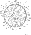
- the rapier wheel 2 of Fig. 1 is shown in isolation in Fig. 2 .
- the rapier wheel 2 shown in Figs. 1 and 2 has an inner ring 20, an outer ring 21, and a number of spokes 22, 23 extending between the inner ring 20 and the outer ring 21 and connecting the inner ring 20 with the outer ring 21.
- the inner ring 20 is configured for mounting the rapier wheel 2 via the inner ring 20 to a drive shaft 10.
- a number of through holes 200 are provided in the rapier wheel 2, in particular six evenly distributed through holes 200 are provided, for a screw connection 7 between the inner ring 20 and the drive shaft 10.
- a connection ring 11 is provided onto which the rapier wheel 2 is fixed by six bolts 8 extending through the through holes 200 and four bolts 9 are provided for fixing the connection ring 11 to the drive shaft 10.
- the outer ring 21 is provided with teeth 210 configured to engage with the rapier 6 for driving the rapier 6 back-and-forth.
- the spokes 22, 23 are arranged crosswise forming pairs of spokes 24, each pair of spokes 24 comprising a first spoke 22 and a second spoke 23.
- the first spoke 22 and the second spoke 23 of each pair of spokes 24 cross each other at a crossing point 25 between the inner ring 20 and the outer ring 21.
- a radial direction 240 (shown by the dotted arrow) through the crossing point 25 of a pair of spokes 24 is referred to as the radial direction 240 of said pair of spokes 24.
- the first spokes 22 and the second spokes 23 are all inclined or tilted with respect to the radial direction 240, wherein the first spokes 22 and the second spokes 23 extend in opposite directions.
- the spokes 22, 23 are identical in shape, wherein the first spoke 22 and the second spoke 23 of each pair of spokes 24 are arranged symmetrically to the radial direction 240 of said pair of spokes 24. Therefore, the crossing points 25 of all pairs of spokes 24 are arranged on a first imaginary circle 250 (shown by a dotted line).
- the first spokes 22 and the second spokes 23 are each convexly curved toward the outer ring 21.
- the spokes 22, 23 extend entirely along a path which seen in the radial direction 240 of the associated pair of spokes 24 is above virtual straight lines 220, 230 (shown as dotted lines in Fig. 2 ) connecting ends of the spokes 22, 23 at the inner ring 20 and the outer ring 21.
- the crossing point 25 of the first spoke 22 and the second spoke 23 is closer to the outer ring 21 than a crossing point 252 of the two virtual straight lines 220, 230 crossing each other.
- a curvature 222 (shown by a dotted line) of the spokes 22 starts at a center 205 of the rapier wheel 2 and increases towards the outer ring 21. In the embodiment shown, the curvature 222 increases continuously towards the outer ring 21.
- a curvature 223 (shown by a dotted line) of the spokes 23 is similar as the curvature 222 of the spokes 22.
- the rapier 6 driven by the rapier wheel 2 exerts forces on the outer ring 21.
- the convexly curved spokes 22, 23 arranged in pairs of spokes 24 allow to counter tangential forces as well as radial forces exerted on the outer ring 21 by the rapier 6, wherein resulting bending stresses on the spokes 22, 23 due to external forces can be reduced.
- the pairs of spokes 24 are evenly distributed about the rapier wheel 2.
- eleven pairs of spokes 24 are provided, wherein first spokes 22 and second spokes 23 of two immediately neighboring pairs of spokes 24 cross at second crossing points 26.
- the second crossing points 26 are arranged on a second imaginary circle 260 (shown by a dotted line) having a smaller radius than the first imaginary circle 250.
- the second imaginary circle 260 is at a region of the inner ring 20, wherein triangular connecting areas 27 are formed between the inner ring 20 and the first spokes 22 and the second spokes 23 of the two immediately neighboring pairs of spokes 24.
- the connecting areas 27 in the embodiment shown are closed. In other words, triangles formed by the spokes 22, 23 of adjacent pairs of spokes 24 and the inner ring 20 are filled with material.
- transition regions 212 between the spokes 22, 23 and the outer ring 21 are reinforced, for example have an increasing surface near the outer ring 21.
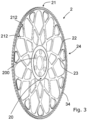
- the axial width of the spokes 22, 23, thus the width in the direction of the axis of rotation of the rapier wheel 2, is variable from the inner ring 20 towards the outer ring 21.
- the axial width decreases from the inner ring 20 towards the outer ring 21, wherein in particular the axial width of the spokes 22, 23 decreases continuously from the inner ring 20 towards the outer ring 21.
- the axial width of the inner ring 20 is constant, the axial width of the spokes 22, 23 decreases in the radial direction 240 towards the outer ring 21, and near the outer ring 21 the axial width of the rapier wheel 2 increases again via a chamfer 34 towards the outer ring 21.
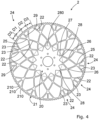
- Fig. 4 shows a second embodiment of a rapier wheel 2 having an inner ring 20, an outer ring 21, and a number of convexly curved first spokes 22 and second spokes 23 extending between the inner ring 20 and the outer ring 21.
- the first spokes 22 and the second spokes 23 are arranged in pairs of spokes 24 having a crossing point 25, wherein in the embodiment shown in Fig. 4 , thirteen pairs of spokes 24 are provided.
- the number of pairs of spokes 24 is increased, whereas a diameter of the rapier wheel 2 remains at least essentially unchanged, the pairs of spokes 24 are arranged closer to each other. Therefore, in the embodiment shown in Fig. 4 , each first spoke 22 crosses second spokes 23 of two other pairs of spokes 24 at second crossing points 26 and third crossing points 28, respectively.
- the third crossing points 28 are arranged on a third imaginary circle 280 (shown by a dotted line).
- Triangular connecting areas 27 are formed between the inner ring 20 and the first spokes 22 and the second spokes 23 of two different pairs of spokes 24 that cross each other at the third crossing point 28.
- the connecting areas 27 in the embodiment shown are closed, i.e. filled with material.
- a straight supporting rod 29 is provided that extends in radial direction 240 between the crossing point 25 of each pair of spokes 24 and the outer ring 21.
- a distance D1 between the first spoke 22 and the supporting rod 29 of each pair of spokes 24 is the same as a distance D2 between the second spoke 23 and the supporting rod 29 of said pair of spokes 24.
- the pairs of spokes 24 are evenly distributed and a number of pairs of spokes 24 can be chosen with respect to a diameter of the rapier wheel 2, so that in the circumferential direction of the outer ring 21 the distance D1 between the first spoke 22 and the supporting rod 29 of each pair of spokes 24 is the same as a distance D3 between the first spokes 22 and the second spokes 23 of immediately neighboring pairs of spokes 24.
- Fig. 5 shows a third embodiment of a rapier wheel 2 having an inner ring 20, an outer ring 21, and a number of convexly curved first spokes 22 and second spokes 23 extending between the inner ring 20 and the outer ring 21.
- the first spokes 22 and the second spokes 23 are arranged in pairs of spokes 24 having a crossing point 25, wherein in the embodiment shown in Fig. 4 , fifteen pairs of spokes 24 are provided.
- the number of pairs of spokes 24 is further increased, whereas a diameter of the rapier wheel 2 remains at least essentially unchanged, the pairs of spokes 24 are arranged closer to each other. Therefore, in the embodiment shown in Fig.
- each first spoke 22 crosses second spokes 23 of four other pairs of spokes 24 at second crossing points 26, third crossing points 28, fourth crossing points 30 and fifth crossing points 32, respectively.
- the fifth crossing points 32 are arranged on a fourth imaginary circle 320 (shown by a dotted line).
- Triangular connecting areas 27 are formed between the inner ring 20 and the first spokes 22 and the second spokes 23 of different pairs of spokes 24 that cross each other at the fifth crossing point 32.
- the connecting areas 27 in the embodiment shown are closed, i.e. filled with material.
- supporting rods 29 are provided that extend between the crossing points 25 of the pairs of spokes 24 and the outer ring 21.
- the rapier wheels 2 shown in the above described embodiments are all flat, i.e. all spokes 22, 23 as well as all crossing points 25, 26, 28, 30, 32 are arranged in a common plane.
- Fig. 6 shows a fourth embodiment of a rapier wheel 2 similar to the rapier wheel shown in Fig. 5 and having an inner ring 20, an outer ring 21, and a number of convexly curved first spokes 22 and second spokes 23 extending between the inner ring 20 and the outer ring 21.
- the thickness of the spokes 22, 23 along the plane of the rapier wheel 2 decreases towards the outer ring 21, wherein in particular the thickness of the spokes 22, 23 decreases continuously towards the outer ring 21.
- Y-shaped supporting rods 33 are provided that extend between the crossing points 25 of the pairs of spokes 24 and the outer ring 21.
- rapier wheels shown in the figures are only by way of example. Further embodiments may be achieved by combination of features and elements that have been described in association to different embodiments within the scope of the appended claims.
Landscapes
- Engineering & Computer Science (AREA)
- Textile Engineering (AREA)
- Tires In General (AREA)
- Molds, Cores, And Manufacturing Methods Thereof (AREA)
- Looms (AREA)
Description
- The invention relates to a rapier wheel for a rapier weaving machine and to a rapier weaving machine with such a rapier wheel.
- As generally known, in rapier weaving machines, a gripper is attached at the front end of a rapier for moving the gripper through a shed. The rapier is driven by a rapier wheel arranged next to the shed. The rapier can be a flexible gripper band or a more rigid gripper rod.
- A rapier wheel is shown for example in
EP 3 262 222 B1 - It is the object of the invention to provide a rapier wheel having a low moment of inertia about its drive shaft that has a high rigidity and durability. It is a further object of the invention to provide a rapier weaving machine with such a rapier wheel.
- These objects are solved by the rapier wheel and the rapier weaving machine with the features of
claims 1 and 15. Preferred embodiments are defined in the dependent claims. - According to a first aspect, a rapier wheel for a rapier weaving machine is provided, the rapier wheel having an inner ring, an outer ring, and a number spokes, wherein the inner ring is configured and adapted for mounting the inner ring to a drive shaft, wherein the outer ring is provided with teeth configured and adapted for engaging with a rapier for driving the rapier, wherein the spokes extend between the inner ring and the outer ring and connect the inner ring with the outer ring, wherein the spokes are arranged crosswise in pairs of spokes comprising a first spoke and a second spoke, wherein the first spoke and the second spoke extend in opposite directions and cross each other at a crossing point between the inner ring and the outer ring, and wherein the first spoke and the second spoke are each convexly curved toward the outer ring.
- In other words, in contrast to
prior art EP 3 262 222 B1 , in accordance with the invention, the first spokes and the second spokes are each convexly curved toward the outer ring. - In the context of the application, curved spokes, that extend either entirely or in portion along a path which seen in an outward radial direction of the associated pair of spokes is above a virtual straight line connecting ends of the spokes at the inner ring and the outer ring, are referred to as "convexly curved toward the outer ring". As a result of the convex curvature, the crossing point of the first spoke and the second spoke is closer to the outer ring than a crossing point of two virtual straight lines crossing each other, wherein each virtual straight line connects an end point of a spoke of a pair of spokes at the inner ring and an end point of this spoke at the outer ring.
- Throughout this description and the claims, the indefinite article "a" or "an" means "one or more". Reference to "a first element" does not mandate presence of "a second element". Further, the expressions "first" and "second" are only used to distinguish elements from one another and are not to be interpreted as indicating any order.
- The first spokes and the second spokes are also conjointly referred to as spokes.
- Providing convexly curved spokes allows to counter tangential forces as well as radial forces exerted on the outer ring by the rapier, wherein resulting bending stresses on the spokes due to external forces can be reduced or even be avoided. Hence, in an ideal configuration, only pressure forces or tensile forces are acting on the spokes.
- The rapier wheel rotates back and forth. Therefore, according to the invention, the spokes are provided in pairs, wherein the two spokes of each pair are curved in opposite directions. The spokes curved in opposite directions allow to counter forces regardless of a direction of rotation of the rapier wheel.
- The first spoke for example is curved in a clockwise direction, i.e., its end point at the outer ring is angularly offset in a clockwise direction from its endpoint at the inner ring. In this case, the second spoke is curved in a counterclockwise direction, i.e., its end point at the outer ring is angularly offset in a counterclockwise direction from its end point at the inner ring. The expressions first and second in this context are only intended to distinguish the spokes from each other and not to indicate any relevance or order of the spokes. The shape of the spokes is chosen, such that the first spoke of each pair of spokes does not cross any other first spoke, and the second spoke of each pair of spokes does not cross any other second spoke.
- The rapier wheel is manufactured for example by injection molding, milling, waterjet cutting or punching.
- In one embodiment, each spoke has a constant radius of curvature, wherein the radius of curvature is the same for all spokes.
- In other embodiments, a curvature of each of the spokes starts at a center of the rapier wheel and increases towards the outer ring. In other words, the spokes are spirally curved. In one embodiment, the curvature increases continuously towards the outer ring. The spokes extend between an outer edge of the inner ring and an inner edge of the outer ring. However, a curvature of the spokes starts at an imaginary line at the center of the rapier wheel. The expression "starts at a center" is not to be interpreted in such way that the imaginary line has its center of origin at the center of the rapier wheel. In one embodiment, the curvature is chosen such that the curvature asymptotically approaches the center of the rapier wheel.
- In one embodiment, spokes that differ in shape are provided. In other embodiments, the first spokes and the second spokes have a same shape, wherein the first spoke and the second spoke of each pair of spokes are arranged symmetrically to a radial direction through the crossing point of this pair of spokes. When providing spokes having a same shape, the crossing points of all pairs of spokes are arranged on a first imaginary circle.
- In one embodiment, in addition to a curvature towards the outer ring, the spokes are also curved in a direction of an axis of rotation of the rapier wheel. In another embodiment, the first spokes and the second spokes are arranged in two parallel planes, wherein in one embodiment the spokes of each pair are connected to each other at the crossing points. In particular embodiments, the rapier wheel is flat, wherein the first spokes and the second spokes are arranged in a common plane.
- In embodiments, the pairs of spokes are evenly distributed about the rapier wheel. Depending on the number of spokes, the size of the rapier wheel and the size of the spokes, the first spoke of each pair of spokes does only cross the second spoke of the associated pair of spokes, or in addition crosses one or more second spokes of other pairs of spokes.
- In one embodiment, the crossing points of the pairs of spokes are arranged on a first imaginary circle, wherein the first spokes and the second spokes of two immediately neighboring pairs of spokes cross at second crossing points, wherein the second crossing points are arranged on a second imaginary circle having a smaller radius than the first imaginary circle. In the context of the invention, pairs of spokes that are successively arranged along the circumference of the outer ring are referred to as immediately neighboring pairs of spokes.
- In one embodiment, only the first spokes and the second spokes of immediately neighboring pairs of spokes cross each other. In this case, in one embodiment, the second imaginary circle is at a region of the inner ring, wherein connecting areas are formed between the inner ring and the first spokes and the second spokes of the two pairs of spokes.
- In one embodiment each first spoke crosses the second spokes of two or more pairs of spokes. In case the first spokes cross the second spokes of more than one other pair of spokes, an imaginary circle of the crossing points decreases with the distance between the pairs of spokes at the outer ring.
- In one embodiment, an imaginary circle of crossing points between the first spoke and the second spoke furthest away from the first spoke in a circumferential direction of the rapier wheel, but still crossing the first spoke, is at a region of the inner ring, wherein connecting areas are formed between the inner ring and the first spokes and the second spokes of the two associated pairs of spokes.
- The connecting areas at the inner ring in particular embodiments are closed. In the context of the application, the expression "area ... is closed" is used to describe that the area is filled with material. When the first spokes and the second spokes of different pairs of spokes cross each other in a region close to an outer edge of the inner ring, essentially triangular connecting areas are formed, wherein when filling the connecting area, an inner ring having a starshaped outer edge is formed.
- In one embodiment, supporting rods are provided that extend between the crossing points of the pairs of spokes and the outer ring. The supporting rods extend in the radial direction of the pair of spokes to provide an additional support of the outer ring. In one embodiment, straight supporting rods are provided. For example, the supporting rods are arranged centered between the first spokes and the second spokes. Hence, in a circumferential direction of the outer ring a distance between the first spoke and the supporting rod of each pair of spokes is the same as a distance between the second spoke and the supporting rod of said pair of spokes. In other embodiments, Y-shaped supporting rods are provided.
- In one embodiment, straight supporting rods are provided that extend in radial direction between the crossing point of each pair of spokes and the outer ring. Preferably, the pairs of spokes are evenly distributed, so that in the circumferential direction of the outer ring the distance between the first spoke and the supporting rod of each pair of spokes is the same as a distance between the first spokes and the second spokes of immediately neighboring pairs of spokes. Therefore, the supporting rods allow that the outer ring is supported at a plurality of at least essentially equidistantly arranged regions in the circumferential direction.
- In one embodiment, transition regions between the first spokes and the outer ring and between the second spokes and the outer ring are reinforced. Due to the design of the rapier wheel having convexly curved spokes, only local stresses occur, which are not distributed over a large area of the rapier wheel. Hence, by reinforcing only a transition region between the spokes and the outer ring, a durability of the rapier wheel can be increased without or at least without a significant increase of the moment of inertia about the drive shaft and/or the weight of the rapier wheel.
- In one embodiment, the number of pairs of spokes is uneven, wherein in particular the number is eleven, thirteen or fifteen. Providing an uneven number of spokes is preferred to minimize warping effects during manufacturing of the rapier wheel and/or during operation of the rapier wheel.
- According to a second aspect, a rapier weaving machine having a rapier wheel with pairs of spokes comprising a first spoke and a second spoke is provided, wherein the first spoke and the second spoke extend in opposite directions and cross each other at a crossing point between the inner ring and the outer ring, and wherein the first spoke and the second spoke are each convexly curved toward the outer ring.
- In the following, embodiments of the invention will be described in detail with reference to the drawings. Throughout the drawings, the same elements will be denoted by the same reference numerals.
- Fig. 1
- shows a part of a weaving machine with a rapier wheel for a rapier.
- Fig. 2
- shows the rapier wheel of
Fig. 1 in isolation. - Fig. 3
- shows a perspective view of the rapier wheel of
Fig. 2 . - Fig. 4
- shows a second embodiment of a rapier wheel.
- Fig. 5
- shows a third embodiment of a rapier wheel.
- Fig. 6
- shows a fourth embodiment of a rapier wheel.
-
Fig. 1 shows a part of a weavingmachine 1 with arapier wheel 2 for driving arapier 6. At the periphery of therapier wheel 2, twoguide blocks arched guide section 5 are provided for guiding therapier 6 at therapier wheel 2. Therapier wheel 2 ofFig. 1 is shown in isolation inFig. 2 . - The
rapier wheel 2 shown inFigs. 1 and2 has aninner ring 20, anouter ring 21, and a number ofspokes inner ring 20 and theouter ring 21 and connecting theinner ring 20 with theouter ring 21. - The
inner ring 20 is configured for mounting therapier wheel 2 via theinner ring 20 to adrive shaft 10. In the embodiment shown inFigs. 1 and2 , for this purpose, a number of through holes 200 (seeFig. 2 ) are provided in therapier wheel 2, in particular six evenly distributed throughholes 200 are provided, for ascrew connection 7 between theinner ring 20 and thedrive shaft 10. To this end, for example, aconnection ring 11 is provided onto which therapier wheel 2 is fixed by sixbolts 8 extending through the throughholes 200 and fourbolts 9 are provided for fixing theconnection ring 11 to thedrive shaft 10. - The
outer ring 21 is provided withteeth 210 configured to engage with therapier 6 for driving therapier 6 back-and-forth. - The
spokes spokes 24, each pair ofspokes 24 comprising afirst spoke 22 and asecond spoke 23. The first spoke 22 and the second spoke 23 of each pair ofspokes 24 cross each other at acrossing point 25 between theinner ring 20 and theouter ring 21. A radial direction 240 (shown by the dotted arrow) through thecrossing point 25 of a pair ofspokes 24 is referred to as theradial direction 240 of said pair ofspokes 24. Thefirst spokes 22 and thesecond spokes 23 are all inclined or tilted with respect to theradial direction 240, wherein thefirst spokes 22 and thesecond spokes 23 extend in opposite directions. - In the embodiment shown, the
spokes spokes 24 are arranged symmetrically to theradial direction 240 of said pair ofspokes 24. Therefore, the crossing points 25 of all pairs ofspokes 24 are arranged on a first imaginary circle 250 (shown by a dotted line). - The
first spokes 22 and thesecond spokes 23 are each convexly curved toward theouter ring 21. As schematically shown inFig. 2 , thespokes radial direction 240 of the associated pair ofspokes 24 is above virtualstraight lines 220, 230 (shown as dotted lines inFig. 2 ) connecting ends of thespokes inner ring 20 and theouter ring 21. As shown inFig. 2 , due to the convex curvature, thecrossing point 25 of the first spoke 22 and the second spoke 23 is closer to theouter ring 21 than acrossing point 252 of the two virtualstraight lines - In the embodiment shown, a curvature 222 (shown by a dotted line) of the
spokes 22 starts at acenter 205 of therapier wheel 2 and increases towards theouter ring 21. In the embodiment shown, thecurvature 222 increases continuously towards theouter ring 21. A curvature 223 (shown by a dotted line) of thespokes 23 is similar as thecurvature 222 of thespokes 22. - In use, the
rapier 6 driven by therapier wheel 2 exerts forces on theouter ring 21. The convexlycurved spokes spokes 24 allow to counter tangential forces as well as radial forces exerted on theouter ring 21 by therapier 6, wherein resulting bending stresses on thespokes - The pairs of
spokes 24 are evenly distributed about therapier wheel 2. In the embodiment shown inFigs. 1 and2 , eleven pairs ofspokes 24 are provided, whereinfirst spokes 22 andsecond spokes 23 of two immediately neighboring pairs ofspokes 24 cross at second crossing points 26. The second crossing points 26 are arranged on a second imaginary circle 260 (shown by a dotted line) having a smaller radius than the firstimaginary circle 250. - In the embodiment shown, the second
imaginary circle 260 is at a region of theinner ring 20, wherein triangular connectingareas 27 are formed between theinner ring 20 and thefirst spokes 22 and thesecond spokes 23 of the two immediately neighboring pairs ofspokes 24. The connectingareas 27 in the embodiment shown are closed. In other words, triangles formed by thespokes spokes 24 and theinner ring 20 are filled with material. - In the embodiment shown,
transition regions 212 between thespokes outer ring 21 are reinforced, for example have an increasing surface near theouter ring 21. - As shown in
Fig. 3 the axial width of thespokes rapier wheel 2, is variable from theinner ring 20 towards theouter ring 21. For example, the axial width decreases from theinner ring 20 towards theouter ring 21, wherein in particular the axial width of thespokes inner ring 20 towards theouter ring 21. As shown inFig. 3 the axial width of theinner ring 20 is constant, the axial width of thespokes radial direction 240 towards theouter ring 21, and near theouter ring 21 the axial width of therapier wheel 2 increases again via achamfer 34 towards theouter ring 21. -
Fig. 4 shows a second embodiment of arapier wheel 2 having aninner ring 20, anouter ring 21, and a number of convexly curvedfirst spokes 22 andsecond spokes 23 extending between theinner ring 20 and theouter ring 21. Thefirst spokes 22 and thesecond spokes 23 are arranged in pairs ofspokes 24 having acrossing point 25, wherein in the embodiment shown inFig. 4 , thirteen pairs ofspokes 24 are provided. As in comparison toFigs. 1 and2 the number of pairs ofspokes 24 is increased, whereas a diameter of therapier wheel 2 remains at least essentially unchanged, the pairs ofspokes 24 are arranged closer to each other. Therefore, in the embodiment shown inFig. 4 , each first spoke 22 crossessecond spokes 23 of two other pairs ofspokes 24 at second crossing points 26 and third crossing points 28, respectively. The third crossing points 28 are arranged on a third imaginary circle 280 (shown by a dotted line). - Triangular connecting
areas 27 are formed between theinner ring 20 and thefirst spokes 22 and thesecond spokes 23 of two different pairs ofspokes 24 that cross each other at thethird crossing point 28. The connectingareas 27 in the embodiment shown are closed, i.e. filled with material. - In the embodiment shown in
Fig. 4 , a straight supportingrod 29 is provided that extends inradial direction 240 between thecrossing point 25 of each pair ofspokes 24 and theouter ring 21. In a circumferential direction of theouter ring 21, a distance D1 between the first spoke 22 and the supportingrod 29 of each pair ofspokes 24 is the same as a distance D2 between the second spoke 23 and the supportingrod 29 of said pair ofspokes 24. In the embodiment shown inFig. 4 , the pairs ofspokes 24 are evenly distributed and a number of pairs ofspokes 24 can be chosen with respect to a diameter of therapier wheel 2, so that in the circumferential direction of theouter ring 21 the distance D1 between the first spoke 22 and the supportingrod 29 of each pair ofspokes 24 is the same as a distance D3 between thefirst spokes 22 and thesecond spokes 23 of immediately neighboring pairs ofspokes 24. -
Fig. 5 shows a third embodiment of arapier wheel 2 having aninner ring 20, anouter ring 21, and a number of convexly curvedfirst spokes 22 andsecond spokes 23 extending between theinner ring 20 and theouter ring 21. Thefirst spokes 22 and thesecond spokes 23 are arranged in pairs ofspokes 24 having acrossing point 25, wherein in the embodiment shown inFig. 4 , fifteen pairs ofspokes 24 are provided. As in comparison toFig. 4 , the number of pairs ofspokes 24 is further increased, whereas a diameter of therapier wheel 2 remains at least essentially unchanged, the pairs ofspokes 24 are arranged closer to each other. Therefore, in the embodiment shown inFig. 4 , each first spoke 22 crossessecond spokes 23 of four other pairs ofspokes 24 at second crossing points 26, third crossing points 28, fourth crossing points 30 and fifth crossing points 32, respectively. The fifth crossing points 32 are arranged on a fourth imaginary circle 320 (shown by a dotted line). - Triangular connecting
areas 27 are formed between theinner ring 20 and thefirst spokes 22 and thesecond spokes 23 of different pairs ofspokes 24 that cross each other at thefifth crossing point 32. The connectingareas 27 in the embodiment shown are closed, i.e. filled with material. In the embodiment shown inFig. 4 , supportingrods 29 are provided that extend between the crossing points 25 of the pairs ofspokes 24 and theouter ring 21. - The
rapier wheels 2 shown in the above described embodiments are all flat, i.e. allspokes points -
Fig. 6 shows a fourth embodiment of arapier wheel 2 similar to the rapier wheel shown inFig. 5 and having aninner ring 20, anouter ring 21, and a number of convexly curvedfirst spokes 22 andsecond spokes 23 extending between theinner ring 20 and theouter ring 21. As can be seen the thickness of thespokes rapier wheel 2 decreases towards theouter ring 21, wherein in particular the thickness of thespokes outer ring 21. For example, Y-shaped supportingrods 33 are provided that extend between the crossing points 25 of the pairs ofspokes 24 and theouter ring 21. - The rapier wheels shown in the figures are only by way of example. Further embodiments may be achieved by combination of features and elements that have been described in association to different embodiments within the scope of the appended claims.
Claims (15)
- Rapier wheel for a rapier weaving machine having an inner ring (20), an outer ring (21), and a number of spokes (22, 23), wherein the inner ring (20) is configured for mounting the inner ring (20) to a drive shaft (10), wherein the outer ring (21) is provided with teeth (210) configured for engaging with a rapier (6) for driving the rapier (6), wherein the spokes (22, 23) extend between the inner ring (20) and the outer ring (21) and connect the inner ring (20) with the outer ring (21), wherein the spokes (22, 23) are arranged crosswise in pairs of spokes (24) comprising a first spoke (22) and a second spoke (23), and wherein the first spoke (22) and the second spoke (23) extend in opposite directions and cross each other at a crossing point (25) between the inner ring (20) and the outer ring (21), characterized in that the first spoke (22) and the second spoke (23) are each convexly curved toward the outer ring (21).
- Rapier wheel according to claim 1, characterized in that a curvature (222) of the first spokes (22) and a curvature (223) of the second spokes (23) in each case starts at a center (205) of the rapier wheel (2) and increases towards the outer ring (21), wherein in particular the curvature (222) increases continuously towards the outer ring (21).
- Rapier wheel according to claim 1 or 2, characterized in that the first spokes (22) and the second spokes (23) have one same shape, wherein the first spoke (22) and the second spoke (23) of each pair of spokes (24) are arranged symmetrically to a radial direction (240) through the crossing point (25) of this pair of spokes (24).
- Rapier wheel according to claim 1, 2 or 3 characterized in that the rapier wheel (2) is flat, wherein the first spokes (22) and the second spokes (23) are arranged in a common plane.
- Rapier wheel according to any one of claims 1 to 4, characterized in that the pairs of spokes (24) are evenly distributed about the rapier wheel (2).
- Rapier wheel according to claim 5, characterized in that the crossing points (25) of the pairs of spokes (24) are arranged on a first imaginary circle (250), wherein the first spokes (22) and the second spokes (23) of two immediately neighboring pairs of spokes (24) cross at second crossing points (26), wherein the second crossing points (26) are arranged on a second imaginary circle (260) having a smaller radius than the first imaginary circle (250).
- Rapier wheel according to claim 6, characterized in that the second imaginary circle (260) is at a region of the inner ring (20), wherein connecting areas (27) are formed between the inner ring (20) and the first spokes (22) and the second spokes (23) of the two pairs of spokes (24).
- Rapier wheel according to claim 6, characterized in that each first spoke (22) crosses the second spokes (23) of two or more pairs of spokes (24).
- Rapier wheel according to claim 8, characterized in that an imaginary circle (280, 320) of crossing points (28, 32) between the first spoke (22) and the second spoke (23) furthest away from the first spoke (22) in a circumferential direction of the rapier wheel (2), but still crossing the first spoke (22), is at a region of the inner ring (20), wherein connecting areas (27) are formed between the inner ring (20) and the first spokes (22) and the second spokes (23) of the two associated pairs of spokes (24).
- Rapier wheel according to any one of claims 7 or 9, characterized in that the connecting areas (27) at the inner ring (20) are closed.
- Rapier wheel according to any one of claims 1 to 10, characterized in that supporting rods are provided that extend between the crossing points (25) of the pairs of spokes (24) and the outer ring (21), in particular straight supporting rods (29) are provided that extend in radial direction (240) between the crossing point (25) of each pair of spokes (24) and the outer ring (21).
- Rapier wheel according to claim 11, characterized in that the straight supporting rods (29) are provided that extend in radial direction (240) between the crossing point (25) of each pair of spokes (24) and the outer ring (21), wherein in a circumferential direction of the outer ring (21) a distance (D1) between the first spoke (22) and the supporting rod (29) of each pair of spokes (24) is the same as a distance (D2) between the second spoke (23) and the supporting rod (29) of said pair of spokes (24), wherein in particular the pairs of spokes (24) are evenly distributed, so that in the circumferential direction of the outer ring (21) the distance (D1) between the first spoke (22) and the supporting rod (29) of each pair of spokes (24) is the same as a distance (D3) between the first spokes (22) and the second spokes (23) of immediately neighboring pairs of spokes (24) and the distance (D2) between the second spoke (23) and the supporting rod (29) of each pair of spokes (24) is the same as a distance (D3) between the first spokes (22) and the second spokes (23) of immediately neighboring pairs of spokes (24).
- Rapier wheel according to any one of claims 1 to 12, characterized in that transition regions (212) between the outer ring (21) and the first spokes (22) and between the outer ring (21) and the second spokes (23) are reinforced.
- Rapier wheel according to any one of claims 1 to 13, characterized in that the number of pairs of spokes (24) is uneven, wherein in particular the number is eleven, thirteen or fifteen.
- Rapier weaving machine having a rapier wheel (2) according to any one of claims 1 to 14.
Priority Applications (4)
| Application Number | Priority Date | Filing Date | Title |
|---|---|---|---|
| EP21182508.8A EP4112792B1 (en) | 2021-06-29 | 2021-06-29 | Rapier wheel |
| BE20220033A BE1029465B1 (en) | 2021-06-29 | 2022-05-18 | Lance wheel for a lance weaving machine |
| CN202280046962.3A CN117597478B (en) | 2021-06-29 | 2022-06-13 | Rapier Wheel |
| PCT/EP2022/065992 WO2023274701A1 (en) | 2021-06-29 | 2022-06-13 | Rapier wheel |
Applications Claiming Priority (1)
| Application Number | Priority Date | Filing Date | Title |
|---|---|---|---|
| EP21182508.8A EP4112792B1 (en) | 2021-06-29 | 2021-06-29 | Rapier wheel |
Publications (3)
| Publication Number | Publication Date |
|---|---|
| EP4112792A1 EP4112792A1 (en) | 2023-01-04 |
| EP4112792C0 EP4112792C0 (en) | 2024-12-25 |
| EP4112792B1 true EP4112792B1 (en) | 2024-12-25 |
Family
ID=76730281
Family Applications (1)
| Application Number | Title | Priority Date | Filing Date |
|---|---|---|---|
| EP21182508.8A Active EP4112792B1 (en) | 2021-06-29 | 2021-06-29 | Rapier wheel |
Country Status (4)
| Country | Link |
|---|---|
| EP (1) | EP4112792B1 (en) |
| CN (1) | CN117597478B (en) |
| BE (1) | BE1029465B1 (en) |
| WO (1) | WO2023274701A1 (en) |
Family Cites Families (8)
| Publication number | Priority date | Publication date | Assignee | Title |
|---|---|---|---|---|
| DE3130904C2 (en) * | 1981-08-05 | 1983-10-27 | Bayerische Motoren Werke AG, 8000 München | Brake disc for a disc brake of a motor vehicle, in particular a motorcycle |
| JPH11107113A (en) * | 1997-09-30 | 1999-04-20 | Toyota Autom Loom Works Ltd | Picking device in rapier loom |
| DE102011007813A1 (en) * | 2011-04-20 | 2012-10-25 | Hauni Maschinenbau Ag | spoked |
| CN202072867U (en) * | 2011-04-24 | 2011-12-14 | 曹俊峰 | Rapier wheel for rapier loom |
| DE102014003441B4 (en) * | 2014-03-10 | 2021-12-23 | Fraunhofer-Gesellschaft zur Förderung der angewandten Forschung e.V. | Method for forming a drive element and a drive element |
| BE1022754B1 (en) * | 2015-02-26 | 2016-08-30 | Picanol Nv | GUIDANCE DEVICE FOR A LANS FOR A GRIPPER WEAVING MACHINE |
| CN209353029U (en) * | 2018-12-10 | 2019-09-06 | 江苏悦达家纺制品有限公司 | A kind of sword wheel on rapier loom arrow shaft wefting insertion |
| WO2020126004A1 (en) * | 2018-12-20 | 2020-06-25 | Volvo Truck Corporation | A gear wheel |
-
2021
- 2021-06-29 EP EP21182508.8A patent/EP4112792B1/en active Active
-
2022
- 2022-05-18 BE BE20220033A patent/BE1029465B1/en active IP Right Grant
- 2022-06-13 CN CN202280046962.3A patent/CN117597478B/en active Active
- 2022-06-13 WO PCT/EP2022/065992 patent/WO2023274701A1/en not_active Ceased
Also Published As
| Publication number | Publication date |
|---|---|
| CN117597478B (en) | 2026-03-17 |
| EP4112792C0 (en) | 2024-12-25 |
| BE1029465B1 (en) | 2023-03-22 |
| WO2023274701A1 (en) | 2023-01-05 |
| CN117597478A (en) | 2024-02-23 |
| EP4112792A1 (en) | 2023-01-04 |
| BE1029465A1 (en) | 2023-01-06 |
Similar Documents
| Publication | Publication Date | Title |
|---|---|---|
| US4045149A (en) | Platform for a swing root turbomachinery blade | |
| KR890002274B1 (en) | Method of manufacturing a filament wound article | |
| US3837178A (en) | Flexible shaft coupling | |
| KR20210028567A (en) | Gear wheel | |
| US6491499B1 (en) | Axial flow fan | |
| EP4112792A1 (en) | Rapier wheel | |
| US6500071B1 (en) | Flexible coupling | |
| EP2642130B1 (en) | Impeller for axially conveying fluids, particularly for refrigeration systems | |
| EP4048589A1 (en) | Tension torsion strap with arched winding pattern | |
| KR20080066767A (en) | Multi screw extruder | |
| US3783481A (en) | Curved roll | |
| CN110621817A (en) | Roller for a carding machine | |
| US20080166234A1 (en) | Blade and Fan Having the Same | |
| FI57714B (en) | FOERBAETTRADE YTTERDAECK | |
| US9528222B2 (en) | Feed screw arrangement | |
| KR20190026919A (en) | A transport device comprising a guide roller and a plurality of rollers | |
| SI25993A (en) | Washing machine drum pulley made of plastic material | |
| EP1967474B1 (en) | Web spreader roll | |
| AU2019422740A1 (en) | Grinding disc and use of such a grinding disc | |
| EP4345325B1 (en) | Drive shaft with non-cylindrical shape and spaced reinforcements | |
| JP3732367B2 (en) | pump | |
| EP3550069B1 (en) | Machine for manufacturing cables | |
| EP0868118A1 (en) | Improved sharpened blade for rotating screw feeders of cutting-mixing machines | |
| CN115698423B (en) | Blade segment for a refiner | |
| US3119553A (en) | Fan wheel construction |
Legal Events
| Date | Code | Title | Description |
|---|---|---|---|
| PUAI | Public reference made under article 153(3) epc to a published international application that has entered the european phase |
Free format text: ORIGINAL CODE: 0009012 |
|
| STAA | Information on the status of an ep patent application or granted ep patent |
Free format text: STATUS: THE APPLICATION HAS BEEN PUBLISHED |
|
| AK | Designated contracting states |
Kind code of ref document: A1 Designated state(s): AL AT BE BG CH CY CZ DE DK EE ES FI FR GB GR HR HU IE IS IT LI LT LU LV MC MK MT NL NO PL PT RO RS SE SI SK SM TR |
|
| STAA | Information on the status of an ep patent application or granted ep patent |
Free format text: STATUS: REQUEST FOR EXAMINATION WAS MADE |
|
| 17P | Request for examination filed |
Effective date: 20230704 |
|
| RBV | Designated contracting states (corrected) |
Designated state(s): AL AT BE BG CH CY CZ DE DK EE ES FI FR GB GR HR HU IE IS IT LI LT LU LV MC MK MT NL NO PL PT RO RS SE SI SK SM TR |
|
| GRAP | Despatch of communication of intention to grant a patent |
Free format text: ORIGINAL CODE: EPIDOSNIGR1 |
|
| STAA | Information on the status of an ep patent application or granted ep patent |
Free format text: STATUS: GRANT OF PATENT IS INTENDED |
|
| INTG | Intention to grant announced |
Effective date: 20240801 |
|
| GRAS | Grant fee paid |
Free format text: ORIGINAL CODE: EPIDOSNIGR3 |
|
| GRAA | (expected) grant |
Free format text: ORIGINAL CODE: 0009210 |
|
| STAA | Information on the status of an ep patent application or granted ep patent |
Free format text: STATUS: THE PATENT HAS BEEN GRANTED |
|
| AK | Designated contracting states |
Kind code of ref document: B1 Designated state(s): AL AT BE BG CH CY CZ DE DK EE ES FI FR GB GR HR HU IE IS IT LI LT LU LV MC MK MT NL NO PL PT RO RS SE SI SK SM TR |
|
| REG | Reference to a national code |
Ref country code: GB Ref legal event code: FG4D |
|
| REG | Reference to a national code |
Ref country code: CH Ref legal event code: EP |
|
| REG | Reference to a national code |
Ref country code: DE Ref legal event code: R096 Ref document number: 602021023795 Country of ref document: DE |
|
| REG | Reference to a national code |
Ref country code: IE Ref legal event code: FG4D |
|
| U01 | Request for unitary effect filed |
Effective date: 20250117 |
|
| U07 | Unitary effect registered |
Designated state(s): AT BE BG DE DK EE FI FR IT LT LU LV MT NL PT RO SE SI Effective date: 20250123 |
|
| PG25 | Lapsed in a contracting state [announced via postgrant information from national office to epo] |
Ref country code: HR Free format text: LAPSE BECAUSE OF FAILURE TO SUBMIT A TRANSLATION OF THE DESCRIPTION OR TO PAY THE FEE WITHIN THE PRESCRIBED TIME-LIMIT Effective date: 20241225 |
|
| PG25 | Lapsed in a contracting state [announced via postgrant information from national office to epo] |
Ref country code: NO Free format text: LAPSE BECAUSE OF FAILURE TO SUBMIT A TRANSLATION OF THE DESCRIPTION OR TO PAY THE FEE WITHIN THE PRESCRIBED TIME-LIMIT Effective date: 20250325 |
|
| PG25 | Lapsed in a contracting state [announced via postgrant information from national office to epo] |
Ref country code: GR Free format text: LAPSE BECAUSE OF FAILURE TO SUBMIT A TRANSLATION OF THE DESCRIPTION OR TO PAY THE FEE WITHIN THE PRESCRIBED TIME-LIMIT Effective date: 20250326 |
|
| PG25 | Lapsed in a contracting state [announced via postgrant information from national office to epo] |
Ref country code: RS Free format text: LAPSE BECAUSE OF FAILURE TO SUBMIT A TRANSLATION OF THE DESCRIPTION OR TO PAY THE FEE WITHIN THE PRESCRIBED TIME-LIMIT Effective date: 20250325 |
|
| PG25 | Lapsed in a contracting state [announced via postgrant information from national office to epo] |
Ref country code: SM Free format text: LAPSE BECAUSE OF FAILURE TO SUBMIT A TRANSLATION OF THE DESCRIPTION OR TO PAY THE FEE WITHIN THE PRESCRIBED TIME-LIMIT Effective date: 20241225 |
|
| PG25 | Lapsed in a contracting state [announced via postgrant information from national office to epo] |
Ref country code: PL Free format text: LAPSE BECAUSE OF FAILURE TO SUBMIT A TRANSLATION OF THE DESCRIPTION OR TO PAY THE FEE WITHIN THE PRESCRIBED TIME-LIMIT Effective date: 20241225 |
|
| PG25 | Lapsed in a contracting state [announced via postgrant information from national office to epo] |
Ref country code: ES Free format text: LAPSE BECAUSE OF FAILURE TO SUBMIT A TRANSLATION OF THE DESCRIPTION OR TO PAY THE FEE WITHIN THE PRESCRIBED TIME-LIMIT Effective date: 20241225 |
|
| PG25 | Lapsed in a contracting state [announced via postgrant information from national office to epo] |
Ref country code: IS Free format text: LAPSE BECAUSE OF FAILURE TO SUBMIT A TRANSLATION OF THE DESCRIPTION OR TO PAY THE FEE WITHIN THE PRESCRIBED TIME-LIMIT Effective date: 20250425 |
|
| PG25 | Lapsed in a contracting state [announced via postgrant information from national office to epo] |
Ref country code: SK Free format text: LAPSE BECAUSE OF FAILURE TO SUBMIT A TRANSLATION OF THE DESCRIPTION OR TO PAY THE FEE WITHIN THE PRESCRIBED TIME-LIMIT Effective date: 20241225 |
|
| PGFP | Annual fee paid to national office [announced via postgrant information from national office to epo] |
Ref country code: TR Payment date: 20250625 Year of fee payment: 5 |
|
| PG25 | Lapsed in a contracting state [announced via postgrant information from national office to epo] |
Ref country code: CZ Free format text: LAPSE BECAUSE OF FAILURE TO SUBMIT A TRANSLATION OF THE DESCRIPTION OR TO PAY THE FEE WITHIN THE PRESCRIBED TIME-LIMIT Effective date: 20241225 |
|
| U20 | Renewal fee for the european patent with unitary effect paid |
Year of fee payment: 5 Effective date: 20250624 |
|
| PLBE | No opposition filed within time limit |
Free format text: ORIGINAL CODE: 0009261 |
|
| STAA | Information on the status of an ep patent application or granted ep patent |
Free format text: STATUS: NO OPPOSITION FILED WITHIN TIME LIMIT |
|
| REG | Reference to a national code |
Ref country code: CH Ref legal event code: L10 Free format text: ST27 STATUS EVENT CODE: U-0-0-L10-L00 (AS PROVIDED BY THE NATIONAL OFFICE) Effective date: 20251105 |
|
| 26N | No opposition filed |
Effective date: 20250926 |
|
| REG | Reference to a national code |
Ref country code: CH Ref legal event code: H13 Free format text: ST27 STATUS EVENT CODE: U-0-0-H10-H13 (AS PROVIDED BY THE NATIONAL OFFICE) Effective date: 20260127 |
|
| PG25 | Lapsed in a contracting state [announced via postgrant information from national office to epo] |
Ref country code: MC Free format text: LAPSE BECAUSE OF FAILURE TO SUBMIT A TRANSLATION OF THE DESCRIPTION OR TO PAY THE FEE WITHIN THE PRESCRIBED TIME-LIMIT Effective date: 20241225 |
|
| GBPC | Gb: european patent ceased through non-payment of renewal fee |
Effective date: 20250629 |
|
| PG25 | Lapsed in a contracting state [announced via postgrant information from national office to epo] |
Ref country code: GB Free format text: LAPSE BECAUSE OF NON-PAYMENT OF DUE FEES Effective date: 20250629 |
|
| PG25 | Lapsed in a contracting state [announced via postgrant information from national office to epo] |
Ref country code: IE Free format text: LAPSE BECAUSE OF NON-PAYMENT OF DUE FEES Effective date: 20250629 |
|
| PG25 | Lapsed in a contracting state [announced via postgrant information from national office to epo] |
Ref country code: CH Free format text: LAPSE BECAUSE OF NON-PAYMENT OF DUE FEES Effective date: 20250630 |
|
| U20 | Renewal fee for the european patent with unitary effect paid |
Year of fee payment: 6 Effective date: 20260331 |