EP4112515A1 - Sheet suction device, sheet conveyor, and printer - Google Patents
Sheet suction device, sheet conveyor, and printer Download PDFInfo
- Publication number
- EP4112515A1 EP4112515A1 EP22179880.4A EP22179880A EP4112515A1 EP 4112515 A1 EP4112515 A1 EP 4112515A1 EP 22179880 A EP22179880 A EP 22179880A EP 4112515 A1 EP4112515 A1 EP 4112515A1
- Authority
- EP
- European Patent Office
- Prior art keywords
- sheet
- suction
- drum
- region
- suction device
- Prior art date
- Legal status (The legal status is an assumption and is not a legal conclusion. Google has not performed a legal analysis and makes no representation as to the accuracy of the status listed.)
- Pending
Links
Images


Classifications
-
- B—PERFORMING OPERATIONS; TRANSPORTING
- B65—CONVEYING; PACKING; STORING; HANDLING THIN OR FILAMENTARY MATERIAL
- B65H—HANDLING THIN OR FILAMENTARY MATERIAL, e.g. SHEETS, WEBS, CABLES
- B65H5/00—Feeding articles separated from piles; Feeding articles to machines
- B65H5/22—Feeding articles separated from piles; Feeding articles to machines by air-blast or suction device
- B65H5/222—Feeding articles separated from piles; Feeding articles to machines by air-blast or suction device by suction devices
- B65H5/226—Feeding articles separated from piles; Feeding articles to machines by air-blast or suction device by suction devices by suction rollers
-
- B—PERFORMING OPERATIONS; TRANSPORTING
- B41—PRINTING; LINING MACHINES; TYPEWRITERS; STAMPS
- B41J—TYPEWRITERS; SELECTIVE PRINTING MECHANISMS, i.e. MECHANISMS PRINTING OTHERWISE THAN FROM A FORME; CORRECTION OF TYPOGRAPHICAL ERRORS
- B41J11/00—Devices or arrangements of selective printing mechanisms, e.g. ink-jet printers or thermal printers, for supporting or handling copy material in sheet or web form
- B41J11/0085—Using suction for maintaining printing material flat
-
- B—PERFORMING OPERATIONS; TRANSPORTING
- B41—PRINTING; LINING MACHINES; TYPEWRITERS; STAMPS
- B41J—TYPEWRITERS; SELECTIVE PRINTING MECHANISMS, i.e. MECHANISMS PRINTING OTHERWISE THAN FROM A FORME; CORRECTION OF TYPOGRAPHICAL ERRORS
- B41J13/00—Devices or arrangements of selective printing mechanisms, e.g. ink-jet printers or thermal printers, specially adapted for supporting or handling copy material in short lengths, e.g. sheets
- B41J13/10—Sheet holders, retainers, movable guides, or stationary guides
- B41J13/22—Clamps or grippers
- B41J13/223—Clamps or grippers on rotatable drums
- B41J13/226—Clamps or grippers on rotatable drums using suction
-
- B—PERFORMING OPERATIONS; TRANSPORTING
- B65—CONVEYING; PACKING; STORING; HANDLING THIN OR FILAMENTARY MATERIAL
- B65H—HANDLING THIN OR FILAMENTARY MATERIAL, e.g. SHEETS, WEBS, CABLES
- B65H2406/00—Means using fluid
- B65H2406/30—Suction means
- B65H2406/33—Rotary suction means, e.g. roller, cylinder or drum
- B65H2406/332—Details on suction openings
-
- B—PERFORMING OPERATIONS; TRANSPORTING
- B65—CONVEYING; PACKING; STORING; HANDLING THIN OR FILAMENTARY MATERIAL
- B65H—HANDLING THIN OR FILAMENTARY MATERIAL, e.g. SHEETS, WEBS, CABLES
- B65H2406/00—Means using fluid
- B65H2406/30—Suction means
- B65H2406/36—Means for producing, distributing or controlling suction
- B65H2406/361—Means for producing, distributing or controlling suction distributing vacuum from stationary element to movable element
- B65H2406/3612—Means for producing, distributing or controlling suction distributing vacuum from stationary element to movable element involving a shoe in sliding contact with flanges of a rotating element
-
- B—PERFORMING OPERATIONS; TRANSPORTING
- B65—CONVEYING; PACKING; STORING; HANDLING THIN OR FILAMENTARY MATERIAL
- B65H—HANDLING THIN OR FILAMENTARY MATERIAL, e.g. SHEETS, WEBS, CABLES
- B65H2406/00—Means using fluid
- B65H2406/30—Suction means
- B65H2406/36—Means for producing, distributing or controlling suction
- B65H2406/362—Means for producing, distributing or controlling suction adjusting or controlling distribution of vacuum transversally to the transport direction, e.g. according to the width of material
- B65H2406/3622—Means for producing, distributing or controlling suction adjusting or controlling distribution of vacuum transversally to the transport direction, e.g. according to the width of material adjusting or controlling distribution of vacuum in the transport direction
-
- B—PERFORMING OPERATIONS; TRANSPORTING
- B65—CONVEYING; PACKING; STORING; HANDLING THIN OR FILAMENTARY MATERIAL
- B65H—HANDLING THIN OR FILAMENTARY MATERIAL, e.g. SHEETS, WEBS, CABLES
- B65H2511/00—Dimensions; Position; Numbers; Identification; Occurrences
- B65H2511/10—Size; Dimensions
-
- B—PERFORMING OPERATIONS; TRANSPORTING
- B65—CONVEYING; PACKING; STORING; HANDLING THIN OR FILAMENTARY MATERIAL
- B65H—HANDLING THIN OR FILAMENTARY MATERIAL, e.g. SHEETS, WEBS, CABLES
- B65H2511/00—Dimensions; Position; Numbers; Identification; Occurrences
- B65H2511/10—Size; Dimensions
- B65H2511/11—Length
-
- B—PERFORMING OPERATIONS; TRANSPORTING
- B65—CONVEYING; PACKING; STORING; HANDLING THIN OR FILAMENTARY MATERIAL
- B65H—HANDLING THIN OR FILAMENTARY MATERIAL, e.g. SHEETS, WEBS, CABLES
- B65H2511/00—Dimensions; Position; Numbers; Identification; Occurrences
- B65H2511/10—Size; Dimensions
- B65H2511/12—Width
-
- B—PERFORMING OPERATIONS; TRANSPORTING
- B65—CONVEYING; PACKING; STORING; HANDLING THIN OR FILAMENTARY MATERIAL
- B65H—HANDLING THIN OR FILAMENTARY MATERIAL, e.g. SHEETS, WEBS, CABLES
- B65H2557/00—Means for control not provided for in groups B65H2551/00 - B65H2555/00
- B65H2557/30—Control systems architecture or components, e.g. electronic or pneumatic modules; Details thereof
- B65H2557/37—Control systems architecture or components, e.g. electronic or pneumatic modules; Details thereof for fluid control
-
- B—PERFORMING OPERATIONS; TRANSPORTING
- B65—CONVEYING; PACKING; STORING; HANDLING THIN OR FILAMENTARY MATERIAL
- B65H—HANDLING THIN OR FILAMENTARY MATERIAL, e.g. SHEETS, WEBS, CABLES
- B65H2801/00—Application field
- B65H2801/03—Image reproduction devices
- B65H2801/12—Single-function printing machines, typically table-top machines
-
- B—PERFORMING OPERATIONS; TRANSPORTING
- B65—CONVEYING; PACKING; STORING; HANDLING THIN OR FILAMENTARY MATERIAL
- B65H—HANDLING THIN OR FILAMENTARY MATERIAL, e.g. SHEETS, WEBS, CABLES
- B65H2801/00—Application field
- B65H2801/03—Image reproduction devices
- B65H2801/21—Industrial-size printers, e.g. rotary printing press
Definitions
- aspects of the present disclosure relate to a sheet suction device, a sheet conveyor, and a printer.
- a printer includes a rotation member such as a drum and performs printing while bearing a sheet on the drum to convey the sheet, for example.
- a sheet conveyor includes a bearer, multiple suction holes, a suction device, a first member, and multiple holes.
- the bearer bears the sheet on a peripheral surface of the bearer and rotates.
- the multiple suction holes are formed in a bearing region of the bearer to bear the sheet on the bearer.
- the suction device sucks the sheet through the multiple suction holes.
- the first member is interposed between the multiple suction holes and the suction device.
- the multiple holes are respectively connectable to the suction holes.
- the sheet conveyor includes a second member that rotates in conjunction with a rotation of the bearer The first member is rotated to change a number of the suction holes communicating with the suction device in the multiple suction holes.
- the multiple suction holes in the bearing region are disposed in a circumferential direction and an axial direction of a bearer (see Japanese Unexamined Patent Application Publication No. 2020-019637 ).
- the sheet conveyor disclosed above may cause a problem in which a sheet may float from a baring surface of the bearer when the bearer bears the sheet having a large size.
- An object of the present invention is to provide a sheet suction that can reduce lifting of the sheet from the bearing surface of the bearing member.
- a sheet suction device includes a drum having multiple suction ports in a circumferential surface of the drum, the drum configured to bear a sheet on the circumferential surface and rotate in a circumferential direction of the drum, and a suction device configured to suck the sheet through the multiple suction ports to attract the sheet on the circumferential surface.
- the drum includes multiple suction regions aligned in the circumferential direction on the circumferential surface, each of the multiple suction regions includes the multiple suction ports aligned in the circumferential direction and in an axial direction of the drum on the circumferential surface, the multiple suction regions include an upstream region, a middle region, and a downstream region in the circumferential direction, and the middle region has the multiple suction ports at both outer sides in the axial direction of the drum.
- the sheet suction device according to the present embodiment can reduce lifting of the sheet from the bearing surface of the bearing member.
- FIGS. 1 and 2 Next, a printer 1 according to a first embodiment of the present disclosure is described with reference to FIGS. 1 and 2 .
- FIG. 1 is a schematic side view of the printer 1 according to the first embodiment of the present disclosure.
- FIG. 2 is a plan view of an example of a discharge unit 23 of the printer 1.
- the printer 1 includes a loading device 10, a printing device 20, a drying device 30, and an ejection device 40.
- the printer 1 applies a liquid to a sheet P conveyed from the loading device 10 by the printing device 20 to perform desired printing, dries the liquid adhering to the sheet P by the drying device 30, and ejects the sheet P to the ejection device 40.
- the loading device 10 includes a loading tray 11 on which a plurality of sheets P are stacked, a feeding unit 12 to separate and feed the sheets P one by one from the loading tray 11, and a resist roller pair 13 to feed the sheet P to the printing device 20.
- Any feeding unit 12 such as a device using a roller or a device using air suction may be used as the feeding unit 12.
- the sheet P delivered from the loading tray 11 by the feeding unit 12 is delivered to the printing device 20 by the resist roller pair 13 being driven at a predetermined timing after a leading end of the sheet P reaches the resist roller pair 13.
- the printing device 20 includes a sheet conveyor 21 to convey the sheet P.
- the sheet conveyor 21 includes a drum 51 and a suction device 52.
- the drum 51 is a bearer (rotating member) that bears the sheet P on a circumferential surface of the drum 51 and rotates.
- the suction device 52 generates a suction force on the circumferential surface of the drum 51.
- the printing device 20 includes a liquid discharge device 22 that discharges the liquid toward the sheet P borne on the drum 51 of the sheet conveyor 21 to apply the liquid onto the sheet P.
- the printing device 20 further includes a transfer cylinder 24 and a delivery cylinder 25.
- the transfer cylinder 24 receives the sheet P fed from the resist roller pair 13 and transfers the sheet P to the drum 51.
- the delivery cylinder 25 delivers the sheet P conveyed by the drum 51 to the drying device 30.
- a leading end of the sheet P conveyed from the loading device 10 to the printing device 20 is gripped by a sheet gripper provided on a surface of the transfer cylinder 24 and is conveyed in accordance with a rotation of the transfer cylinder 24.
- the transfer cylinder 24 forwards the sheet P to the drum 51 at a position opposite (facing) the drum 51.
- the drum 51 includes a sheet gripper on a surface of the drum 51, and the leading end of the sheet P is gripped by the sheet gripper of the drum 51.
- Multiple suction holes are dispersedly formed on the surface of the drum 51.
- the suction device 52 generates a suction airflow from desired multiple suction holes of the drum 51 toward an interior of the drum 51.
- the suction device 52 serves as a suction device.
- the sheet gripper 106 (see FIG, 4 ) of the drum 51 grips the leading end of the sheet P forwarded from the transfer cylinder 24 to the drum 51, and the sheet P is attracted to and borne on the drum 51 by the suction airflow generated by the suction device 52. As the drum 51 rotates, the sheet P is conveyed.
- the liquid discharge device 22 includes discharge units 23 (23A to 23F) that discharge liquids.
- the discharge unit 23A discharges a liquid of cyan (C)
- the discharge unit 23B discharges a liquid of magenta (M)
- the discharge unit 23C discharges a liquid of yellow (Y)
- the discharge unit 23D discharges a liquid of black (K), respectively.
- the discharge units 23E and 23F are used to discharge any one of YMCK or special liquid such as white and gold (silver).
- the liquid discharge device 22 may further include a discharge unit to discharge a processing liquid such as a surface coating liquid.
- the discharge unit 23 is a full line head and includes multiple liquid discharge heads 125 arranged in a staggered manner on a base 127 (see FIG. 2 ).
- Each of the multiple liquid discharge heads 125 includes multiple nozzle arrays 126 and multiple nozzles arranged in each of the multiple nozzle arrays 126, for example, as illustrated in FIG. 2 .
- the "liquid discharge head 125" is simply referred to as a "head 125".
- a discharge operation of each of the discharge units 23 of the liquid discharge device 22 is controlled by drive signals corresponding to print information.
- the liquid of each color is discharged from the discharge units 23, and an image corresponding to the print information is printed on the sheet P.
- the drying device 30 includes a drying mechanism 31 and a suction conveyance mechanism 32.
- the drying mechanism 31 dries the liquid adhered on the sheet P by the printing device 20.
- the suction conveyance mechanism 32 conveys (suctions and conveys) the sheet P while suctioning the sheet P conveyed from the printing device 20 onto the suction conveyance mechanism 32.
- the sheet P conveyed from the printing device 20 is received by the suction conveyance mechanism 32, the sheet P is conveyed to pass through the drying mechanism 31 and delivered to the ejection device 40.
- the liquid on the sheet P is subjected to a drying process by the drying mechanism 31.
- the liquid component such as water in the liquid evaporates.
- the colorant contained in the liquid is fixed on the sheet P.
- curling of the sheet P is reduced.
- the ejection device 40 includes an ejection tray 41 on which multiple sheets P are stacked.
- the sheets P conveyed from the drying device 30 are sequentially stacked and held on the ejection tray 41 of the ejection device 40.
- the printer 1 can further include, for example, a pretreatment device disposed upstream from the printing device 20, or a post-processing device disposed between the drying device 30 and the ejection device 40.
- the pretreatment device performs pretreatment on the sheet P.
- the post-processing device performs post-processing of the sheet P onto which the liquid has been applied.
- the pretreatment device may perform a pretreatment process that applies a treatment liquid onto the sheet P before image is printed on the sheet P.
- the treatment liquid reacts with the liquid to reduce bleeding of the liquid to the sheet P.
- the content of the pretreatment process is not particularly limited to the process as described above.
- the post-processing device may perform a sheet reversing process and a binding process to bind the multiple sheets P, for example.
- the sheet reversing process reverses the sheet P, on which image has been printed by the printing device 20, and conveys the reversed sheet P again to the printing device 20 to print on both sides of the sheet P.
- the printing device 20 according to the first embodiment includes the discharge unit 23 to discharge a liquid.
- the printing device 20 according to the first embodiment may perform printing by a method other than the liquid discharge operation such as an electrographic method.
- the sheet suction device 50 according to a first embodiment of the present disclosure is described with reference to FIG. 3 .
- the sheet conveyor 21 (see FIG. 1 ) includes the sheet suction device 50 that includes the drum 51 and suction device 52.
- FIG. 3 is a schematic side view of an entire structure of a sheet suction device 50 of the printer 1.
- the sheet suction device 50 includes the drum 51, the suction device 52 serving as a suction unit, and a rotary valve 200 serving as a suction region switcher.
- the rotary valve 200 is disposed between the drum 51 and the suction device 52.
- the suction device 52 and the rotary valve 200 are connected with each other via a hose 55a (tube), and the rotary valve 200 and the drum 51 are connected with each other via a hose 55b (tube).
- the hoses 55a and 55b are collectively referred to as a hose 55.
- FIG. 4 is an exploded perspective view of the drum 51.
- FIG. 5 is a plan view of the drum 51 illustrating a sheet size in one bearing region 105 of the drum 51.
- FIG. 6 is an enlarged schematic plan view of a T-portion of FIG. 5 illustrating an arrangement of suction ports and the sheet size in a circumferential direction of the drum 51.
- FIG. 7 is an enlarged schematic plan view of the drum 51 illustrating the arrangement of the suction ports in an axial direction and the circumferential direction of the drum 51, and the sheet size.
- FIG. 8 is a schematic side view of the drum 51 illustrating the bearing region 105 and divided regions of the bearing region 105 of the drum 51.
- the drum 51 includes a drum body 101 and a suction plate 102.
- a sealing material such as a rubber sheet may be interposed between the suction plate 102 and the drum body 101.
- the drum 51 includes three baring regions 105 (105A to 105C) and is bearable a plurality of sheets P in the circumferential direction of the drum 51. As illustrated in FIGS. 3 and 4 , the drum 51 includes three suction plates 102 for the bearing regions 105A to 105C and the drum body 101. The drum body 101 includes three bearing regions 105A to 105C. The suction plate 102 includes multiple suction holes 112 and forms a chamber 113 communicating with each of the multiple suction holes 112.
- the drum body 101 includes a groove shaped suction ports 111 communicating with the chamber 113.
- the drum 51 includes a sheet gripper 106 at a leading end of the bearing region 105 in a rotational direction of the drum 51.
- the sheet gripper 106 is illustrated in a simplified manner in FIG. 4 .
- the suction ports 111 are elongated rectangular through holes penetrating through the drum 51 (see FIG. 6 ). Shapes of the suction ports 111 are different according to positions of the suction ports 111 in the drum 51.
- the multiple suction holes 112 are uniformly formed in the suction plate 102 (see FIG. 4 ), and the multiple suction ports 111 are ununiformly formed in the drum body 101 (see FIG. 6 ).
- the multiple suction ports 111 are rectangular through holes in the drum body 101 (see FIGS. 3 and 7 ).
- sheet areas S1 to S9 corresponding to multiple sheet sizes are allocated to one bearing region 105.
- one bearing region 105 includes twelve suction ports 111a and 111b1 to 111b11 arranged in the circumferential direction (rotation direction) of the drum 51.
- the suction port 111a includes suction ports 111a1 to 111a9 arranged in an axial direction (vertical direction as indicated by arrow in FIG. 7 ) at a leading end in the rotational direction (left end in FIG. 7 ) of the drum 51.
- the suction ports 111a1 to 111a9 respectively correspond to the sheet sizes S1 to S9.
- the drum 51 includes the suction ports 111a1 and 111b1 corresponding to the sheet region S1 (see FIG. 7 ).
- the suction ports 111a1 and 111b1 communicate with the chamber 113 to which the multiple suction holes 112 faces (see FIG. 7 ).
- the drum 51 includes the suction ports 111a2 and 111b2 communicating with the chamber 113 to which the multiple suction holes 112 in the sheet region S2 excluding the sheet region S1 faces (see FIG. 7 ).
- the drum 51 includes the suction ports 111a3, 111b3, and 111b4 communicating with the chamber 113 to which a plurality of suction holes 112 in the sheet region S3 excluding the sheet regions S1 and S2 faces (see FIG. 6 ). The same applies to other sheet regions S4 to S9.
- suction ports 111c3 and 111c9 are disposed on both outer sides of the suction port 111b1 (see FIG. 7 ) in the axial direction of the drum 51.
- the drum 51 includes a suction port 111d9 on both outer sides of suction ports 111b5 (see FIG. 6 ).
- the suction holes 112 communicating with the suction port 111b1 and the suction port 111b5 are suctions holes arranged inside in the axial direction of the drum 51 (axial direction of the bearer).
- the suction holes 112 leading to the suction ports 111c3, 111c9 and 111d9 are suction holes disposed on both outer sides of the drum 51 (see FIG. 6 ).
- one bearing region 105A is divided into multiple suction regions 116 including a first region 116A, a second region 116B, a third region 116C, and a fourth region 116D in the circumferential direction (rotational direction) from a leading end side in the circumferential direction (rotational direction) of the drum 51.
- the drum 51 rotates counterclockwise as indicated by arrows in FIG. 1 .
- the first region 116A, a second region 116B, a third region 116C, and a fourth region 116D may be collectively referred to as a "suction region 116".
- the multiple suction ports 111 are divided into multiple suction regions 116 (116A, 116B, 116C, and 116D) in the circumferential direction, and the multiple suction regions 116 (116A, 116B, 116C, and 116D) includes an upstream region (fourth region 116D), a middle region (second region 116B and third region 116C), and a downstream region (first region 116A) in the circumferential direction.
- the first region 116A is allocated to the suction port 111a at the leading end (left end in FIG. 6 ) in the circumferential direction (rotation direction) of the drum 51 as indicated by arrow in FIG. 6 .
- the circumferential direction (rotation direction) is leftward direction in FIG. 6 .
- the second region 116B is allocated to the suction ports 111b1 to 111b3.
- the third region 116C is allocated to the suction ports 111b4 to 111b8.
- the fourth region 116D is allocated to the suction ports 111b9 to 111b11.
- the sheet suction device 50 includes : a drum 51 having multiple suction ports 111 in a circumferential surface of the drum 51, the drum 51 configured to bear a sheet P on the circumferential surface and rotate in a circumferential direction of the drum 51; and a suction device 52 configured to suck the sheet P through the multiple suction ports to attract the sheet P on the circumferential surface, wherein the multiple suction ports 111 are disposed in the circumferential direction and an axial direction of the drum 51, the multiple suction ports 111 are divided into multiple suction regions 116 (116A, 116B, 116C, and 116D) in the circumferential direction, the multiple suction regions 116 (116A, 116B, 116C, and 116D) includes an upstream region (fourth region 116D), a middle region (second region 116B and third region 116C), and a downstream region (first region 116A) in the circumferential direction, and the middle region (second region 116B and third region 116C)
- the sheet suction device 50 can connect the hose 55 (tube) to each suction port 111 (111a and 111b) on the drum 51 and switch a generation of the negative pressure to each suction port 111 (111a and 111b) to switch the suction regions.
- the rotary valve 200 includes a rotator 202 and a fixing part 201.
- the rotator 202 is a rotating member that rotates together with the drum 51.
- the fixing part 201 is coupled (connected) to the suction device 52, and the fixing part 201 does not rotate together with the drum 51.
- the fixing part 201 forms a switch to switch suction or non-suction (valid or invalid of suction) in the bearing region 105.
- the drum 51 includes an encoder wheel 53 that rotates in synchronization with the drum 51.
- the encoder wheel 53 is attached to a rotation axis 51a of the drum 51.
- the drum 51 includes a feeler 56 that rotates in synchronization with the drum 51.
- the feeler 56 is attached to the drum 51.
- An encoder sensor 54 and a home position sensor 57 are attached to the frame 100 of the printer 1.
- the encoder sensor 54 detects a rotation amount of the encoder wheel 53.
- the HP sensor 57 detects the feeler 56.
- the HP sensor 57 detects the feeler 56 only by one pulse (once) per one rotation of the drum 51 to detect a home position in the rotational direction of the drum 51
- the encoder sensor 54 detects a rotation amount of the encoder wheel 53 to detect a relative rotation amount of the drum 51 from the home position.
- the printer 1 includes a controller (circuitry) that combines detection results of two sensors of the encoder sensor 54 and the HP sensor 57 to detect an absolute phase (rotational phase) of the drum 51 and the rotator 202 of the rotary valve 200 that rotates together with the drum 51.
- the controller (circuitry) of the printer 1 switches a connection (communication) and a disconnection (noncommunication) between the suction hole 112 and the suction device 52 according to a relative phase difference between the rotator 202 and the fixing part 201 to control timing of generation of the negative pressure on the circumferential surface of the drum 51 (see FIG. 3 ).
- the relative phase difference between the rotator 202 and the fixing part 201 is calculated from the detection results of two sensors of the encoder sensor 54 and the HP sensor 57.
- a metal plate processed into a disk shape is used for both the rotator 202 and the fixing part 201.
- FIGS. 9 to 15 illustrates the rotary valve 200 according to the first embodiment of the present disclosure.
- FIG. 9 is a schematic external perspective view of the rotary valve 200.
- FIG. 10 is a schematic cross-sectional perspective view of the rotary valve 200 cut in half.
- FIG. 11 is a schematic enlarged cross-sectional perspective view of a main part of the rotary valve 200 cut in half.
- FIGS. 12A and 12B are schematic perspective views of the fixing part 201 that forms the rotary valve 200.
- FIG. 13 is a schematic side view of the fixing part 201.
- FIGS. 14A and 14B are schematic perspective views of a second member 204 that forms the rotary valve 200.
- FIG. 15 is a schematic side view of the second member 204.
- FIGS. 16A and 16B are schematic perspective views of a first member 203 that forms the rotary valve 200.
- FIG. 17 is a schematic side view of the first member 203.
- FIGS. 18A and 18B are schematic perspective views of a third member 205 that forms the rotary valve 200.
- FIG. 19 is a schematic side view of the third member 205 superposed on the fixing part 201.
- the rotary valve 200 includes the fixing part 201 fixed to the frame 100 of the printer 1.
- the frame 100 supports the drum 51, the transfer cylinder 24, the discharge unit 23, and the like.
- the fixing part 201, the HP sensor 57, and the encoder sensor 54 may be fixed to multiple divided frames or multiple divided brackets.
- the fixing part 201 includes rows of multiple grooves 212 arranged in a radial direction and divided into three parts in the circumferential direction of the fixing part 201 (see FIGS. 12B and 13 ).
- Each groove 212 includes grooves 211 to be coupled to the suction device 52 (see FIGS. 12A and 13 ).
- Rows of the multiple grooves 212 located on the same concentric circle are referred to as a groove row 210A, a groove row 210B, a groove row 210C, and a groove row 210D, respectively as illustrated in FIG. 13 .
- the groove rows 210A, 210B, 210C, and 210D are collectively referred to as a "groove row 210".
- the rotator 202 of the rotary valve 200 includes a first member 203, a second member 204, and a third member 205 (see FIG. 11 ).
- the first member 203, the second member 204, and the third member 205 are arranged in an order of the third member 205, the first member 203, and the second member 204 from the fixing part 201 as illustrated in FIGS. 10 and 11 .
- the first member 203 has a shape covering the outer peripheral surface of the third member 205 in a radial direction of the rotary valve 200 (see FIG. 11 ).
- the third member 205 is fitted into the first member 203.
- the second member 204 is a disk-shaped member including a plurality of (here, nine) holes 241 (241A to 2411) communicating with the suction port 111 of the drum 51 on a circumferential surface of the second member 204 (disk-shaped member).
- Each holes 241 (241A to 2411) includes an opening 241a on a side surface of the second member 204.
- the side surface of the second member 204 contacts with the first member 203.
- the nine holes 241A to 2411 (see FIG. 15 ) arranged in the circumferential direction are communicable with the nine suction ports 111a (111a1 to 111a9) arranged in the axial direction of the drum 51 and are connectable to corresponding one of the plurality of suction holes 112.
- the second member 204 includes multiple types of multiple holes 242 (242A to 2421) on a side surface of the second member 204 (disk-shaped member) or the like (see FIG. 15 ).
- the holes 242A and 242C1 respectively include a through hole 243a1 and 243a3 that penetrates through the second member 204 in the axial direction and grooves 243b extending in the circumferential direction (rotation direction) of the second member 204.
- the grooves 243b respectively communicate with the through holes 243a1 and 243a3.
- Each of the holes 242B, 242C2, 242E, 242G1, and 242H includes a through hole 243a1 that penetrates the second member 204 in the axial direction.
- Each of the holes 242D, 242F, 242G2, and 2421 includes a non-through hole 243c and a hole 243d.
- the non-through hole 243c does not penetrate through the second member 204 in the axial direction of the second member 204.
- the hole 243d extends in the radial direction of the second member 204 from the non-through hole 243c.
- the holes 242 (242A to 2421) as described above also communicates with the suction ports 111.
- the multiple holes 241 are provided corresponding to the respective bearing regions 105A, 105B, and 105C.
- the holes 241 for one bearing region 105 are simply illustrated in FIG. 14 .
- the first member 203 is a disk-shaped member that includes through grooves 231 along a circumferential direction on a side surface of the first member 203 (disk-shaped member).
- the through grooves 231 are provided for each of the bearing regions 105 (105A, 105B, and 105C, see FIGS. 4 and 8 ).
- the first member 203 includes the through grooves 231 (230A, 230B, 230C, and 230D) at four positions that are concentric in the radial direction from the outer circumferential side toward the center of the first member 203.
- Each row of the through grooves 231 positioned at the same concentric circle is collectively referred to as groove rows 230A, 230B, 230C, and 230D, respectively.
- rows of the holes 241 and 242 of the second member 204 corresponding to the groove rows 230A to 230D of the first member 203 are respectively referred to as hole rows 240 (240A to 240D) from the outer circumference side toward the center of the second member 204.
- Each of the rows of the holes 241 and 242 is arranged in the circumferential direction of the second member 204.
- the second member 204 includes the holes 242C1 and 242C2 (see FIG. 15 ).
- the holes 242C1 and 242C2 are two or more holes 242 that are simultaneously and respectively communicate with the groove row 230D and the groove row 230B (see FIG. 17 ) of the grooves 231 of the first member 203 by a rotation of the first member 203 for a unit rotation amount.
- the hole 242C1 belongs to the hole row 240D
- the hole 242C2 belongs to the hole row 240B of the second member 204 (see FIG. 15 ).
- the holes 242C1 and 242C2 are two or more holes 242 that simultaneously communicate with the groove row 230D and the groove row 230B (see FIG. 17 ) of the groove 231 of the first member 203, respectively.
- the holes 242C1 and 242C2 are disposed at different distances from a rotation center "O" of the second member 204 (see FIG. 15 ).
- the two holes 242C1 and 242C2 simultaneously communicate with the groove row 230D and the groove row 230B, respectively.
- the two holes 242C1 and 242C2 respectively belong to the different hole rows 240D and 240B among the multiple hole rows 240 arranged in the radial direction of the second member 204.
- the second member 204 includes the hole 242G1 and 242G2.(see FIG. 15 ).
- the hole 242G1 belongs to the hole row 240B, and the hole 242G2 belongs to the hole row 240C of the second member 204.
- the holes 242G1 and 242G2 are two or more holes 242 that simultaneously communicate with the groove row 230B and the groove row 230C of the grooves 231 of the first member 203 (see FIG. 17 ), respectively, by the rotation of first member 203 for the unit rotation amount.
- the holes 242G1 and 242G2 are the two or more holes 242 that simultaneously communicate with the groove row 230B and the groove row 230C of the grooves 231 of the first member 203 (see FIG. 17 ), respectively.
- the holes 242G1 and 242G2 are disposed at different distances from the rotation center "O" of the second member 204.
- the two holes 242G1 and 242G2 simultaneously communicate with the groove row 230B and the groove row 230C of the first member 203, respectively.
- the two holes 242G1 and 242G2 respectively belong to the different hole rows 240B and 240C among the multiple hole rows 240 arranged in the radial direction of the second member 204.
- the second member 204 includes the two holes 242C1 and 242C2 or the two holes 242G1 and 242G2 that simultaneously communicate with the groove row 230B and the groove row 230C of the first member 203, respectively, by the rotation of the first member 203 for the unit rotation amount.
- the rotary valve 200 can selects one of the two holes 242C1 and 242C2 or selects one of the two holes 242G1 and 242G2 according to a size of the sheet P to be used.
- a switch (rotary valve 200) is configured to switch the multiple suction regions (116A, 116B, 116C, and 116D) to be sucked according to a size of the sheet P.
- the rotary valve 200 closes one of unselected two holes 242C1 and 242C2 or closes one of unselected two holes 242G1 and 242G2 by a plug.
- the rotary valve 200 can easily change the suction region according to a type of a size of the sheet P (destination of the sheet P).
- the third member 205 (see FIGS. 18A and 18B ) having a disk shape includes a through hole 251 through which the grooves 212 of the fixing part 201 and the grooves 231 of the first member 203 communicate with each other (see FIG. 11 ).
- the first member 203, the second member 204, and the third member 205 form the rotator 202 (see FIG. 11 ).
- the first member 203, the second member 204, and the third member 205 rotate along with a rotation of the drum 51 when the sheet P is conveyed.
- the rotary valve 200 changes (switches) the suction region 116 (suction area)
- the rotary valve 200 rotates the first member 203 relative to the second member 204 and the third member 205.
- the third member 205 rotates together with the first member 203.
- Rotation of the first member 203 changes a number of holes 242 of the second member 204 communicating with the grooves 231 of the first member 203.
- a connection status of a suction channel in the rotary valve 200 changes.
- the rotary valve 200 can change (switch) the suction region 116 (suction area) according to the size of the sheet P (destination of the sheet P).
- the sheet suction device 50 includes a switch (rotary valve 200) configured to switch the multiple suction regions 116 (116A, 116B, 116C, and 116D), wherein the switch (rotary valve 200) switches the multiple suction regions 116 (116A, 116B, 116C, and 116D) according to a size of the sheet P.
- a switch rotary valve 200
- FIG. 20 is a side view of the drum 51 illustrating the allocation of the bearing regions 105 and the grooves 231.
- the circumferential surface of the drum 51 is divided into three bearing regions 105 (105A to 105C).
- One bearing region 105 is divided into four regions of the first region 116A to the fourth region 116D.
- the outermost groove row 210A of the fixing part 201 is allocated to the first region 116A.
- the groove row 230A of the first member 203 switches between communication and noncommunication of each suction port 111 of the first region 116A with the suction device 52. That is, the groove row 230A connects and disconnects each suction port 111 of the first region 116A with the suction device 52.
- the groove row 210D is allocated to the second region 116B.
- the groove row 230D of the first member 203 switches between communication and noncommunication of each suction port 111 of the second region 116B with the suction device 52. That is, the groove row 230D connects and disconnects each suction port 111 of the second region 116B with the suction device 52.
- the groove row 210B of the fixing part 201 is allocated to the third region 116C.
- the groove row 230B of the first member 203 switches between communication and noncommunication of each suction port 111 of the third region 116C with the suction device 52.
- the groove row 230B connects and disconnects each suction port 111 of the third region 116C with the suction device 52.
- the groove row 210C of the fixing part 201 is allocated to the fourth region 116D.
- the groove row 230C of the first member 203 switches between communication and noncommunication of each suction port 111 of the fourth region 116D with the suction device 52. That is, the groove row 230C connects and disconnects each suction port 111 of the fourth region 116D with the suction device 52.
- the sheet suction device 50 sucks the first region 116A, the second region 116B, the third region 116C and the fourth region 116D in this order from the downstream side to the upstream side in the circumferential direction.
- FIGS. 21(a) to 21(c) and FIGS. 22(a) to 22(c) illustrate the switching operation (size switching operation) of the suction regions (suction areas) by the relative rotation of the first member 203 and the second member 204.
- FIGS. 21(a) and 22(a) are schematic plan views of the drum 51 illustrating the size of the sheet P and the suction ports 111 on the drum 51.
- FIGS. 21(b) and 22(b) are schematic transparent side views of the first member 203 and the second member 204.
- FIGS. 21(c) and 22(c) are enlarged transparent side views of the first member 203 and the second member 204 in FIGS. 21(b) and 22(b) .
- the nine holes 241A to 2411 in the circumferential direction of the second member 204 communicate with the nine suction ports 111a (111a1 to 111a9) of the drum 51.
- a number of holes 242 of the second member 204 (number of suction ports 111a of the drum 51) communicating with the groove 231 of the groove row 230A of the first member 203 is switched (changed) to switch (change) the size of the suction region 116 (suction area) in the axial direction of the drum 51.
- the axial direction of the drum 51 is orthogonal to the circumferential direction of the drum 51 (see FIGS. 21(a) and 22(a) ).
- the number of holes 242 of the second member 204 (number of suction ports 111a of the drum 51) communicating with the grooves 231 of the first member 203 is switched (changed) to switch (change) the number of the suction holes 112 facing the chamber 113 with which the suction ports 111a of the drum 51 communicate.
- the holes 242 of the second member 204 communicate with any one of the groove rows 230B to 230D of the first member 203.
- the number of suction ports 111b (111b1 to 111b11) of the drum 51 communicating with the groove 231 of the groove rows 230B to 230D of the first member 203 via the holes 242 of the second member 204 is switched (changed) to switch (change) the size of the suction region (suction area) in the circumferential direction of the drum 51.
- the number of suction ports 111b of the drum 51 (number of holes 242 of the second member 204) communicating with the grooves 231 of the first member 203 is switched (changed) to switch (change) the number of the suction holes 112 facing the chamber 113 with which the suction ports 111b of the drum 51 communicate.
- the relative positional relation between the first member 203 and the second member 204 is set to a state in which the groove 231 of the groove row 230A of the first member 203 communicates with the hole 241A of the second member 204, and the groove 231 of the groove row 230D of the first member 203 communicates with the hole 242 of the second member 204.
- the suction device 52 communicates with the suction port 111a1 of the drum 51. Further, the suction device 52 communicates with the suction ports 111b1 of the drum 51.
- the suction device 52 sucks air through the suction holes 112 (see FIGS. 3 and 4 ) belonging to a region BA communicating with the suction port 111a1 and a region BB communicating with the suction port 111b1 so that the suction device 52 can suck the air in the suction region of the sheet region S1.
- the first member 203 is rotated relative to the second member 204 in a direction indicated by arrow "D" illustrated in FIGS. 22(b) and 22(c) so that the relative positional relation between the first member 203 and the second member 204 becomes a state in which the groove 231 of the groove row 230A of the first member 203 communicates with the two holes 241A and 241B of the second member 204, and the groove 231 of the groove row 230D of the first member 203 communicates with the two holes 242A and 242B of the second member 204 (see FIG. 22(c) ).
- shaded circles in FIGS. 22(b) and 22(c) indicate the holes 241 and 242 (i.e. the hole 241B and 242B) that are new holes 241 and 242 of the second member 204 communicating with the groove 231 of the first member 203.
- the suction device 52 communicates with the suction ports 111a1 and 111a2 of the drum 51. Further, the suction device 52 communicates with the suction ports 111b1 and 111b2 of the drum 51.
- the suction device 52 sucks air through the suction holes 112 belonging to a region BA communicating with the suction ports 111a1 and 111a2 and a region BB communicating with the suction ports 111b1 and 111b2 so that the suction device 52 can suck the air in the suction region 116 of the sheet region S2 having an area larger than the sheet region S1.
- FIGS. 23A to 23C , FIGS. 24A to 24C , and FIGS. 25A to 25C illustrate transition of the relative positions between the first member 203 and the second member 204 when the first member 203 is rotated to change the relative positions with the second member 204 in nine rotation steps (nine rotation phases) in the above-described configuration of the rotary valve 200.
- FIGS. 23A to 23C , FIGS. 24Ato 24C , and FIGS. 25A to 25C are schematic transparent side views of the first member 203 and the second member 204. Note that FIG. 23A is the same position as FIG. 21B , and FIG. 23B is the same position as FIG. 22B .
- the holes 241 and 242 of the second member 204 are arranged so that the two or three holes 241 and 242 communicate with one of the bearing regions 105 of the drum 51 for each time the relative position is switched (changed) by one rotation step (one rotation phase).
- the rotary valve 200 according to the first embodiment includes the drum 51 having three bearing regions 105 (105A to 105C, see FIG. 4 ).
- a number of the holes 241 and 242 of the second member 204 communicate with the bearing regions 105 by one rotation step (one rotation phase) of the first member 203 becomes six or nine.
- the number of holes 241 and 242 are set to two or three for one rotation step (one rotation phase) so that the sheet suction device 50 can select the suction regions (suction areas) according to the destination of the sheet P.
- three suction ports 111b of the drum 51 may be allocated to an innermost groove row 230D of the first member 203 via the holes 242 of the second member 204, and five suction ports 111b of the drum 51 may be allocated to the groove row 230C of the first member 203 via the holes 242 of the second member 204.
- two suction ports 111b of the drum 51 may be allocated to the innermost groove row 230D of the first member 203 via the holes 242 of the second member 204, and five suction ports 111b of the drum 51 may be allocated to the groove row 230C of the first member 203 via the holes 242 of the second member 204.
- the drum 51 has suction ports 111c3, 111c9, and 111d9 on both outer sides of the drum 51 in the axial direction of the drum 51.
- the suction ports 111c3, 111c9, and 111d9 are substantially aligned with the corresponding suction ports 111b1, 111b1, and 111b5, respectively.
- the suction ports 111c3, 111c9, and 111d9 in the middle region are respectively aligned in the axial direction of the drum 51. That is, the multiple suction ports 111c3 and 111c9 at said both outer sides in the middle region (second region 116B and third region 116C) are aligned in the circumferential direction of the drum 51.
- the second member 204 of the rotary valve 200 has holes 242 communicating with the suction ports 111c3, 111c9, and 111d9 for the same reason that the drum 51 has suction ports 111a2 to 111a9.
- the radial position of the holes 242 corresponding to each suction port 111c, 111c9, and 111d9 has to be in the same row as the hole row 240 (groove row 230) for corresponding suction region 116.
- the suction ports 111c3 and 111c9 are located at the position of the second region 116B.
- the holes 242 of the second member 204 of the rotary valve 200 corresponding to the suction ports 111c3 and 111c9 are provided in the hole row 240D corresponding to the innermost groove row 230D.
- the suction port 111d9 is located at the position of the third region 116C of the suction regions 116.
- the hole 242 of the second member 204 of the rotary valve 200 corresponding to the suction port 111d9 is provided in the hole row 240B corresponding to the groove row 230B that is third from the innermost groove row 230D toward an outer peripheral side of the first member 203.
- circumferential positions of the holes 242 communicating with the suction ports 111c3, 111c9, and 111d9 correspond to the positions of the suction ports 111c3, 111c9, and 111d9 of the drum 51.
- the axial positions of the suction ports 111c3, 111c9, and 111d9 on both outer sides in the axial direction of the drum 51 are preferably aligned with the corresponding suction ports 111a (111a3 and 111a9) at the downstream side in the circumferential direction of the drum 51.
- the axial positions of the suction ports 111c9 and 111d9 are aligned with the axial position of the suction port 111a9.
- the sheet conveyor 21 including the sheet suction device 50 can reduce the floating of the sheet P at the intermediate portion of the sheet P and stably suction and convey the sheet P even when the sheet P having a large size is conveyed.
- the sheet suction device 50 does not suck a hatched area "A" indicated in FIG. 26 of the sheet P. Therefore, when a sheet conveyor 21 sucks and conveys the sheet P having a size corresponding to the sheet region S9, the middle portion of the sheet P in the conveying direction may float from the bearing surface of the drum 51.
- the sheet P When the sheet P enters the printing area while the sheet P floating from the bearing surface of the drum 51, the sheet P may come into contact with the nozzle surface of the head 125. Further, the liquid may be applied to the sheet P while the sheet P floats from the bearing surface of the drum 51 so that printing quality may decrease.
- the drum 51 according to the first embodiment includes the suction ports 111c3, 111c9, and 111d9 in the region A (see FIGS. 22 and 26 ).
- the sheet suction device 50 can reduce the floating of the sheet P from the bearing surface of the drum 51 at the middle portion of the sheet P when the sheet conveyor 21 suctions and conveys the sheet P having a size corresponding to the sheet region S9. Therefore, the sheet conveyor 21 can stably suck (attracts) and convey the sheet P.
- the number of the suction ports 111c (111c3 and 111c9) and 111d (111d9) may be smaller than the number of the suction ports 111a (nine, for example) as long as the number and arrangement of the suction ports 111c (111c3 and 111c9) and 111d (111d9) can reduce the floating of the sheet P from the bearing surface of the drum 51.
- the suction plate 102 of the sheet suction device 50 includes the multiple suction holes 112 (suction ports) in the bearing region of the drum 51.
- the multiple suction holes 112 of the suction plate 102 are arranged in the circumferential direction and the axial direction of the drum 51.
- the multiple suction holes 112 disposed in the circumferential direction of the suction plate 102 communicate with the suction ports 111a and 111b1 to 111b11.
- the suction ports 111a and 111b1 to 111b11 are coupled to and sucked by the suction device 52 at different timings from the downstream side to the upstream side in the circumferential direction of the drum 51 (see FIG. 22 ).
- the suction device 52 serves as a suction device.
- the suction ports 111c3, 111c9, and 111d9 and the suction ports 111b1 and 111b5 are coupled to and sucked by the suction device 52 at the same timing (see FIG. 6 ).
- the suction ports 111c3, 111c9, and 111d9 communicate with the suction holes 112 disposed on both outer sides in the axial direction of the drum 51.
- the suction ports 111b1 and 111b5 communicate with the suction holes 112 disposed on the inner side in the axial direction of the drum 51.
- the suction device 52 sucks the multiple suction ports 111 of the multiple suction regions 116 (116A, 116B, 116C, and 116D) at different times in an order of the downstream region (first region 116A), the middle region (second region 116B and third region 116C), and the upstream region (fourth region 116D) in a direction opposite to the circumferential direction (rightward direction in FIG.
- the suction device 52 sucks the multiple suction ports 111c3, 111c9, and 111d9 at said both outer sides and the multiple suction ports 111b1 and 111b5 in an inner side between said both outer sides in the axial direction of the drum 51 in the middle region (second region 116B and third region 116C) at the same time.
- the sheet suction device 50 can reduce the floating of the sheet from the bearing surface of the drum 51 (bearer). Therefore, the sheet conveyor 21 can stably suck (attracts) and convey the sheet P.
- the sheet suction device 50 according to a second embodiment of the present disclosure is described below with reference to FIGS. 27(a) and 27(b) .
- FIGS. 27(a) and 27(b) illustrate the sheet suction device 50 according to the second embodiment of the present disclosure.
- FIG. 27(a) is a schematic plan view of the drum 51 illustrating the size of the sheet P and the suction ports 111 on the drum 51.
- FIG. 27(b) is a schematic transparent side view of the first member 203 and the second member 204.
- the sheet suction device 50 includes the suction ports 111c3 and 111c9 in the first embodiment, the circumferential positions of which are different from each other in the circumferential direction of the drum 51 (see FIGS. 22(a) and 27 ). Further, each of the circumferential positions of the suction ports 111c3 and 111c9 is different from the circumferential position of the suction port 111b1 in the circumferential direction of the drum 51 (see FIGS. 22(a) and 27 ).
- the sheet suction device 50 can reduce the floating of the sheet P from the bearing surface of the drum 51 even if the suction ports 111b1, 111c3, and 111c9 are disposed at different positions in the circumferential direction.
- the circumferential positions of the suction ports 111c3 and 111c9 may be within the second region 116B when the suction port 111b1 is sucked (coupled to the suction device 52) at the timing of the second region 116B.
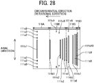
- the sheet suction device 50 according to a third embodiment of the present disclosure is described with reference to FIG. 28 .
- FIG. 28 is a schematic plan view of arrangement of suction ports 111 and suction regions (suction areas) according to the third embodiment of the present disclosure.
- the sheet suction device 50 includes the suction ports 111a (111a1 to 111a9) that are arranged in the axial direction of the drum 51 and are on the downstream side in the circumferential direction of the drum 51.
- the sheet suction device 50 further includes ten suction ports 111 (111b1 to 111b10) that are arranged in the circumferential direction of the drum 51.
- the suction port 111a is disposed in the first region 116A, and the suction ports 111b1 to 111b4 are disposed in the second region 116B.
- the suction ports 111b5 to 111b9 are disposed in the third region 116C, and the suction port 111b10 is disposed in the fourth region 116D.
- the suction ports 111c8 and 111c9 are arranged at different positions in the circumferential direction on both sides in the axial direction of the drum 51 in the second region 116B.
- the suction ports 111c8 and 111c9 serve as suction ports 111 of both outer side in the axial direction of the drum 51.
- the suction ports 111b1 to 111b4 serve as the suction ports 111 of inner side (central side) in the axial direction of the drum 51.
- the suction port 111c8 is disposed within a region corresponding to a difference between the sheet region S7 and the sheet region S8 according to the first embodiment (see FIGS. 6 and 28 ).
- the suction port 111c9 is disposed within a region corresponding to a difference between the sheet region S8 and the sheet region S9 according to the first embodiment (see FIGS. 6 and 28 ).
- the suction ports 111d9 are disposed on both sides in the axial direction of the drum 51 in the third region 116C.
- the suction ports 111d9 serve as suction ports 111 of both outer side in the axial direction of the drum 51.
- the suction ports 111b5 to 111b9 serve as the suction ports 111 of inner side (central side) in the axial direction of the drum 51.
- two suction ports 111c8 and 111c9 are disposed on both outer sides in the axial direction of the drum 51 in the second region 116B that is downstream of the third region 116C.
- One suction port 111d9 is disposed on both outer sides in the axial direction of the drum 51 in the third region 116C that is upstream side in the circumferential direction of the drum 51.
- the number of suction holes 112 sucked at the same timing in the third region 116C is smaller than the number of suction holes 112 sucked at the same timing in the second region 116B.
- the third region 116C is disposed upstream of the second region 116B in the circumferential direction of the drum 51.
- a number of the suction ports 111 in the middle region decreases toward the upstream region (fourth region 116D) in the circumferential direction.
- FIGS. 29A and 29B to FIGS. 34A and 34B are used to illustrate the effects of the above embodiments.
- FIGS 29A , 30A , 31A , 32A , 33A , and 34A are schematic side views of the sheet conveyor 21, the transfer cylinder 24, and the delivery cylinder 25 illustrating a relation between the fixing part 201 and the drum 51.
- FIGS 29B , 30B , 31B , 32B , 33B , and 34B are schematic plan views of the drum 51 illustrating a suctioning and non-suctioning of the suction port 111.
- the sheet conveyor 21 in this embodiment includes a pressing roller 1000 around the drum 51.
- the pressing roller 1000 presses the sheet P against the bearing surface of the drum 51 at a suction start position.
- the drum 51 serves as a bearer.
- the pressing roller (1000) is configured to press the sheet P against the circumferential surface of the drum 51 at the suction start position at which the suction device 52 starts suctioning the sheet P through the multiple suction ports 111.
- the sheet suction device 50 sucks the suction ports 111a1 to 111a9 of the first region 116A shaded (blackened) in FIG. 29B .
- the sheet Pa of the maximum size is attracted to the bearing surface of the drum 51 and pressed against the bearing surface (surface) of the drum 51 by the pressing roller 1000.
- the sheet suction device 50 sucks the suction ports 111b1 to 111b4, and the sheet suction device 50 also sucks the suction ports 111c3 and 111c9 on both sides in the axial direction of the drum 51.
- the suction ports 111b1 to 111b4 are on an inner side in the axial direction of the drum 51 in the second region 116B shaded (blackened) in FIG. 30B .
- the sheet suction device 50 sucks the suction ports 111a1 to 111a9 in the first region 116A and the suction ports 111b1 to 111b4 in the inner side in the axial direction of the drum 51 in the second region 116B shaded (blackened) in FIG. 30B . Therefore, the sheet suction device 50 sucks and attracts a leading end portion side (region of the first region 116A) and a middle portion (region of the second region 116B) of the sheet Pa to the drum 51 so that the sheet suction device 50 can reduce the floating of the sheet Pa from the bearing surface of the drum 51 that cause the sheet Pa coming into contact with the head 125.
- the sheet suction device 50 sucks the suction ports 111c3 and 111c9 on both outer sides in the axial direction of the drum 51 in the second region 116B so that the sheet suction device 50 can reduce the floating of both sides in the axial direction of the middle portion (region of the second region 116B) of the sheet Pa.
- the sheet suction device 50 sucks the suction holes 112 communicating with the suction ports 111b1 to 111b4 and the suction holes 112 communicating with the suction ports 111a1 to 111a9 on the downstream side in the circumferential direction (rotational direciton ) of the drum 51 excluding the suction holes 112 communicating with the suction ports 111a and 111b10 on the upstream side and downstream side in the circumferential direction of the drum 51.
- the sheet suction device 50 does not suck the suction hole 112 communicating with the suction ports 111b5 to 111b10 on the upstream side in the circumferential direction (rotational direciton ) of the drum 51.
- the suction device 52 gradually enlarge the multiple suction regions 116 in the order of the downstream region (first region 116A), the middle region (second region 116B and third region 116C), and the upstream region (fourth region 116D) in the direction opposite to the circumferential direction. That is, the multiple suction regions is gradually enlarged from the downstream region (first region 116A) toward the upstream region (fourth region 116D) in a direction opposite to the circumferential direction.
- the sheet suction device 50 sucks the suction ports 111b5 to 111b9 of the third region 116C shaded (blackened) in FIG. 32B and also sucks the suction ports 111d9 on both outer sides of the drum 51.
- the suction ports 111b4 to 111b9 on the inner side in the axial direction of the drum 51 are sucked and the suction ports 111d9 on both outer sides in the axial direction of the drum 51 are also sucked so that the sheet suction device 50 can reduce the floating of the middle portion of the sheet Pa in the circumferential (rotational) direction.
- the sheet suction device 50 sucks the suction ports 111a1 to 111a9 in the first region 116A, the suction ports 1 11b1 to 11 1b4 on the inner side in the axial direction of the drum 51 in the second region 116B, and the suction ports 111b5 to 111b9 in the inner side in the axial direction of the drum 51 of the third region 116C, which are shaded (blackened) in FIG. 33B .
- the sheet suction device 50 sucks and attracts the leading end portion side (region of the first region 116A) and a middle portion (region of the second region 116B and the third region 116C) of the sheet Pa to the drum 51 so that the sheet suction device 50 can reduce the floating of the sheet Pa from the bearing surface of the drum 51 that causes the sheet Pa coming into contact with the head 125.
- the sheet suction device 50 sucks the suction ports 111c3 and 111c9 on both outer sides in the axial direction of the drum 51 in the second region 116B and the suction port 111d9 on both outer sides in the axial direction of the drum 51 in the third region 116C so that the sheet suction device 50 can reduce the floating of both sides in the axial direction of the middle portion (regions of the second region 116B and the third region 116C) of the sheet Pa.
- the sheet suction device 50 sucks the suction port 111b10 of the fourth region 116D shaded (blackened) in FIG. 34B .
- the sheet suction device 50 sucks all the suction ports 111a1 to 111a9, 111b1 to 111b10, 111c3, 111c9, and 111d9 so that the sheet suction device 50 can reliably reduce the floating of the sheet Pa in the printing area and stably conveys the sheet Pa.
- FIGS. 35A and 35B to FIGS. 40A and 40B are used to illustrate the effects of the present embodiment.
- FIGS 29A , 30A , 31A , 32A , 33A , and 34A are schematic side views of the sheet conveyor 21, the transfer cylinder 24, and the delivery cylinder 25 illustrating a relation between the fixing part 201 and the drum 51.
- FIGS 29B , 30B , 31B , 32B , 33B , and 34B are schematic plan views of the drum 51 illustrating a suctioning and non-suctioning of the suction port 111.
- the sheet suction device 50 suctions (attracts) and conveys the sheet Pb having a size illustrated in FIG. 35B .
- the sheet Pb has a size corresponding to the sheet region S8 in the first embodiment.
- the sheet suction device 50 sucks the suction ports 111a1 to 111a8 of the first region 116A shaded (blackened) in FIG. 35B except the suction port 111a9.
- the sheet suction device 50 includes the suction ports 111a4 to 111b8 that are same as the suction ports 111a4 to 111b8 illustrated in FIGS. 7 , 21 , and 22 in the first embodiment.
- the sheet Pb is pressed against the bearing surface of the drum 51 by the pressing roller 1000 while the sheet Pb is attracted onto the bearing surface of the drum 51.
- the sheet suction device 50 sucks the suction ports 111b1 to 111b4, and the sheet suction device 50 also sucks the suction ports 111c3 on both sides in the axial direction of the drum 51.
- the suction ports 111b1 to 111b4 are on an inner side in the axial direction of the drum 51 in the second region 116B shaded (blackened) in FIG. 36B .
- the suction port 111c9 is not sucked.
- the leading end (first region 116A) of the sheet Pb enters the printing area.
- the first region 116A is the downstream region of the multiple suction regions 116.
- the sheet suction device 50 sucks the suction ports 111a1 to 111a9 in the first region 116A and the suction ports 111b1 to 111b4 in the inner side in the axial direction of the drum 51 in the second region 116B shaded (blackened) in FIG. 37B .
- the sheet suction device 50 sucks and attracts the leading end portion side (region of the first region 116A) and a middle portion (region of the second region 116B and the third region 116C) of the sheet P to the drum 51 so that the sheet suction device 50 can reduce the floating of the sheet P from the bearing surface of the drum 51 that causes the sheet Pa coming into contact with the head 125.
- the sheet suction device 50 sucks the suction ports 111c3 on both outer sides in the axial direction of the drum 51 in the second region 116B so that the sheet suction device 50 can reduce the floating of both sides in the axial direction of the middle portion (region of the second region 116B) of the sheet P.
- the sheet suction device 50 further sucks the suction ports 111b5 to 111b9 in the third region 116C shaded (blackened) in FIG. 38B . At this time, the sheet suction device 50 does not suck the suction ports 111d9 on both sides in the axial direction of the drum 51 in the third region 116C.
- the sheet suction device 50 sucks the suction ports 111b4 to 111b9 on the inner side in the axial direction of the drum 51 to reduce the floating of the middle portion of the sheet Pb.
- the sheet suction device 50 sucks the suction ports 111a1 to 111a9 in the first region 116A, the suction ports 111b1 to 111b4 on the inner side in the axial direction of the drum 51 in the second region 116B, and the suction ports 111b5 to 111b9 in the inner side in the axial direction of the drum 51 in the third region 116C that are shaded (blackened) in FIG. 39B .
- the sheet suction device 50 sucks and attracts the leading end portion side (region of the first region 116A) and the middle portion (region of the second region 116B and the third region 116C) of the sheet P to the drum 51 so that the sheet suction device 50 can reduce the floating of the sheet P from the bearing surface of the drum 51 that causes the sheet P coming into contact with the head 125.
- the sheet suction device 50 sucks the suction ports 116c3 on both outer sides in the axial direction of the drum 51 in the second region 116B so that the sheet suction device 50 can reduce the floating of both sides in the axial direction of the middle portion (regions of the second region 116B and the third region 116C) of the sheet P since the sheet P has smaller size than the sheet Pa as described above.
- the sheet suction device 50 sucks the suction port 111b10 of the drum 51 in the fourth region 116D shaded (blackened) in FIG. 40B .
- the sheet suction device 50 sucks all the suction ports 111a1 to 111a9, 111b1 to 111b10, 111c3, 111c9, and 111d9 so that the sheet suction device 50 can reliably reduce the floating of the sheet P in the printing area and stably conveys the sheet P.
- FIGS. 41 and 42 are schematic side views of the sheet suction device 50 including a switch 400.
- the switch 400 switches suctioning and un-suctioning of the suction port 111 by the sheet suction device 50 in multiple bearing regions of the drum 51 according to the fourth embodiment.
- the sheet suction device 50 includes a switch 400 that includes a fixing part 201 and switch valves 402.
- the switch valves 402 includes switch valves 402a1 to 402d1 and 402a2 to 402d2.
- the fixing part 201 serves as a fixing member.
- the switch valves 402 are multiple opening and closing valves configured to be openably closable.
- FIG. 41 illustrates only a path to the opening and closing valves for two grooves 211 of each groove row 210 of the fixing part 201.
- the groove row 210A of the fixing part 201 has grooves 211A1 to 211A3.
- the groove row 210B includes grooves 211B1 to 211B3
- the groove row 210C includes grooves 211C1 to 211C3
- the groove row 210D includes grooves 211D1 to 211D3.
- the grooves 211A1, 211B1, 211C1 and 211D1 are respectively coupled to the suction device 52 via a common path 403 and individual paths 401a1 to 401d1.
- the individual paths 401a1 to 401d1 respectively include the switch valves 402 (402a1 to 402d1) to respectively open or close the paths between the grooves 211A1, 211B1, 211C1, and 211D1 and the suction device 52.
- the grooves 211A2, 211B2, 211C2 and 211D2 are respectively coupled to the suction device 52 via the common path 403 and individual paths 401a2 to 401d2.
- the individual paths 401a2 to 401d2 respectively include the switch valves 402 (402a2 to 402d2) to respectively open or close the paths between the grooves 211A2, 211B2, 211C2, and 211D2 and the suction device 52.
- the paths of the grooves 211A3 to 211D3 and the switch valves 402 are the same, but are omitted for the sake of simplicity. Further, among the switch valves 402, the switch valves 402 shaded (blackened) are open, and the switch valves 402 not shaded (white color) are closed.
- the switch valves 402a2 to 402d2 are opened so that the grooves 211A2 to 211D2 are coupled to the suction device 52, and the sheet P is suctioned by the grooves 211A2 to 211D2.
- This state of suction is referred to as "suction present” or “suction enabled”.
- the switch valves 402a1 to 402d1 are closed so that the grooves 211A1 to 211D1 are not coupled to the suction device 52.
- a suction operation is not performed (suction disabled) in a region where the sheet P is not borne one the bearing surface of the drum 51.
- the switch valves 402a1 to 402d1 are opened to enable suction of the sheet P by the grooves 211A1 to 211D1 as illustrated in FIG. 42 . Further, the switch valves 402a2 to 402d2 are closed to enable suction of the sheet P by the grooves 211A2 to 211D2.
- the sheet suction device 50 can reduce suctioning of foreign matter such as mist from the suction ports 111 in the bearing region 105 on which the sheet P is not placed.
- FIGS. 43 and 44 are schematic side views of the sheet suction device 50 including the switch 400.
- the switch 400 switches suctioning and un-suctioning of the suction port 111 by the sheet suction device 50 in multiple bearing regions of the drum 51 according to the fifth embodiment.
- the sheet suction device 50 includes the individual paths 401a1 to 401d1 that are collected to one division common path 404A and then collectively coupled to the common path 403.
- the individual paths 401a1 to 401d1 are divided from the individual paths 401a2 to 401d2.
- the individual paths 401a2 to 401d2 are collected to one division common path 404B and then collectively coupled to the common path 403.
- the division common path 404A and 404B respectively include the switch valves 402A and 402B serving as opening and closing valves.
- the switch valve 402A is closed to disable suction of the sheet P by the grooves 211A1 to 211D1, and the switch valve 402B is opened to enable suction of the sheet P by the grooves 211A2 to 211D2 to bear the sheet P on the drum 51.
- the switch valve 402A When the sheet P comes to the position illustrated in FIGS. 29A and 29B by the rotation of the drum 51, the switch valve 402A is opened to enable suction of the sheet P by the grooves 211A1 to 211D1 as illustrated in FIG. 44 . Further, the switch valves 402B is closed to disable suction of the sheet P by the grooves 211A2 to 211D2.
- the sheet suction device 50 can reduce suctioning of foreign matter such as mist from the suction ports 111 in the bearing region on which the sheet P is not placed.
- This sheet suction device 50 includes the switch valves 402A and 402B and the like common to the grooves 211 belonging to the different groove rows 210A to 210D arranged in the radial direction so that the sheet suction device 50 can reduce a number of the switch valves 402 (opening and closing devices).
- the sheet suction device 50 can reduce the number of the switch valves 402 (opening and closing device) since enabling and disabling of the suction operation of the bearing region 105 is set according to units of a surface area of the sheet P borne on the drum 51.
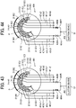
- the sheet suction device 50 according to a sixth embodiment of the present disclosure is described with reference to FIGS. 45 and 46 .
- FIGS. 45 and 46 are schematic side views of the sheet suction device 50 including the switch 400.
- the switch 400 switches suctioning and un-suctioning of the suction port 111 by the sheet suction device 50 in multiple bearing regions of the drum 51 according to the sixth embodiment.
- the sheet suction device 50 includes the individual paths 401a1 to 401d1 that are collected to one division common path 404Aand then collectively coupled to the common path 403.
- the individual paths 401a1 to 401d1 are divided from the individual paths 401a2 to 401d2.
- the individual paths 401a2 to 401d2 are collected to one division common path 404B and then collectively coupled to the common path 403.
- the sheet suction device 50 includes a three way valve 402C as the opening and closing device between the division common paths 404A and 404B and the common path 403.
- the three way valve 402C is switched to disable suction of the sheet P by the grooves 211A1 to 211D1 in FIG. 45 . Further, the three way valve 402C is switched to enable suction of the sheet P by the grooves 211A2 to 211D2.
- the three way valve 402C is switched to enable suction of the sheet P by the grooves 211A1 to 211D1 as illustrated in FIG. 46 . Further, the three way valve 402C is switched to disable suction of the sheet P by the grooves 211A2 to 211D2.
- the sheet suction device 50 can reduce suctioning of foreign matter such as mist from the suction ports 111 in the bearing region on which the sheet P is not placed. Further, the sheet suction device 50 can reduce the number of switch valves 402 (opening and closing devices).
- FIG. 47 is a schematic perspective view of the rotator 202 of the rotary valve 200.
- FIG. 48 is a schematic side view of the rotary valve 200 of FIG. 47 .
- FIG. 49 is an enlarged schematic side view of a main part of the rotator 202 of the rotary valve 200 of FIG. 47 .
- FIG. 50 is an enlarged schematic perspective view of a main part of the rotator 202 of the rotary valve 200 of FIG. 47 .
- the first member 203 of the rotary valve 200 is manually rotatable by the user.
- the first member 203 is manually rotated by the user to switch the suction regions.
- An index plunger 206 is used to rotate the first member 203.
- a rotation operation of the first member 203 is also referred to as a "suction region changing (switching) operation".
- a leading end of the index plunger 206 is fitted into one of holes 252 formed on a circumferential surface of the third member 205 according to each position of the suction region (suction area) to determine the position of the suction region.
- the user pulls out the index plunger 206 from the hole 252 and rotates the first member 203 relative to the second member 204 and the third member 205 to a target position. Then, the user inserts the leading end of the index plunger 206 into the hole 252 at the target position.
- a scale 238 having nine steps, for example, is formed on the circumferential surface of the first member 203 to indicate a rotation position of the first member 203 so that the user can recognize a setting state of the first member 203.
- a scale 218 as a reference for the scale 238 of the first member 203 may be formed on a circumferential surface of the fixing part 201.
- the drum 51 is fixed at a predetermined phase (predetermined position) to change the suction region such as a "sheet size changing mode", for example, so that the user can access the index plunger 206. Further, the drum 51 is fixed at the predetermined phase (predetermined position) so that the drum 51 is not rotated by an operational force of the user operating the index plunger 206.
- FIG. 51 is a schematic enlarged perspective view of a main part of the rotary valve 200 illustrating the acquisition of the size information of the suction region (suction area).
- the photosensor 207 is disposed on the fixing part 201 that does not rotate along with the drum 51, and the first member 203 includes a sensing piece (feeler) detectable by the photosensor 207.
- the rotary valve 200 including the photosensor 207 can detect the detection piece (feeler) by the photosensor 207 for each one rotation of the drum 51 with a rotation of the first member 203 rotating together with the drum 51.
- the photosensor 207 detects the feeler and generates one pulse for each one rotation of the drum 51.
- the drum 51 having similar configuration can detect one pulse from the feeler on the drum 51 and detect another one pulse from the feeler on the first member 203 during one rotation of the drum 51 so that the rotary valve 200 can obtain a total of two pulses from two systems (drum 51 and first member 203) during one rotation of the drum 51.
- the first member 203 has a phase difference with the second member 204 that rotates together with the drum 51.
- intervals between the pulses generated from each of the drum 51 rotating at a constant speed and the first member 203 are measured to detect a rotation angle of the first member 203.
- the relative phase difference that is, the setting information of the suction region can be acquired.
- FIG. 52 is a schematic external perspective view of the rotary valve 200.
- FIG. 53 is a cross-sectional perspective view of the rotary valve 200 cut in half.
- FIG. 54 is a schematic enlarged cross-sectional perspective view of a main part of the rotary valve 200 cut in half.
- FIGS. 55A and 55B are schematic perspective views of the second member 204 that forms the rotary valve 200.
- FIG. 56 is a side view of the second member 204.
- the second member 204 according to the seventh embodiment includes a combination of the first member 203 and the third member 205 according to the first embodiment. Further, the second member 204 according to the first embodiment is the first member 203 according to the seventh embodiment.
- the second member 204 is a disk-shaped member that includes through grooves 245a, grooves 245b, and through holes 245c corresponding to each bearing region 105 (bearing area) on a side surface of the second member 204 (disk-shaped member).
- the through grooves 245a are along a circumferential direction of the second member 204.
- Each of the grooves 245b has a bottom.
- the through hole 245c is on the side surface of the second member 204.
- the through hole 245c penetrate through the second member 204.
- the second member 204 includes grooves 245a, for example, arranged at four locations on the concentric circles from the outer circumference toward the center in the radial direction of the second member 204.
- the first member 203 is rotate relative to the second member 204 to change the size of the suction region that is the number of the suction holes 112 connected to the suction device 52, in the seventh embodiment of the present disclosure.
- the switch is a rotary valve 200 configured to switch the multiple suction regions to be sucked according to a rotation of the first member 203 relative to the second member 204.
- the second member 204 rotates together with the drum 51. Since a distance between the suction port 111 of the drum 51 and a connection port of the hose 55 of the rotator 202 of the rotary valve 200 varies according to the rotation of the first member 203, the rotary valve 200 according to the seventh embodiment has a configuration of a piping adjustable according to a variation (change) of the distance between the suction port 111 and the connection port of the hose 55.
Abstract
A sheet suction device (50) includes a drum (51) having multiple suction ports (111) in a circumferential surface of the drum (51), the drum (51) configured to bear a sheet (P) on the circumferential surface and rotate in a circumferential direction of the drum (51), and a suction device (52) configured to suck the sheet (P) through the multiple suction ports (111) to attract the sheet (P) on the circumferential surface. The drum (51) includes multiple suction regions (116A, 116B, 116C, and 116D) aligned in the circumferential direction on the circumferential surface, each of the multiple suction regions (116A, 116B, 116C, and 116D) includes the multiple suction ports (111) aligned in the circumferential direction and in an axial direction of the drum (51) on the circumferential surface, the multiple suction regions (116A, 116B, 116C, and 116D) include an upstream region (116D), a middle region (116B and 116C), and a downstream region (116A) in the circumferential direction, and the middle region (116B and 116C) has the multiple suction ports (111c3, 111c9, and 111d9) at both outer sides in the axial direction of the drum (51).
Description
- Aspects of the present disclosure relate to a sheet suction device, a sheet conveyor, and a printer.
- A printer includes a rotation member such as a drum and performs printing while bearing a sheet on the drum to convey the sheet, for example.
- A sheet conveyor includes a bearer, multiple suction holes, a suction device, a first member, and multiple holes. The bearer bears the sheet on a peripheral surface of the bearer and rotates. The multiple suction holes are formed in a bearing region of the bearer to bear the sheet on the bearer. The suction device sucks the sheet through the multiple suction holes. The first member is interposed between the multiple suction holes and the suction device.
- The multiple holes are respectively connectable to the suction holes. The sheet conveyor includes a second member that rotates in conjunction with a rotation of the bearer The first member is rotated to change a number of the suction holes communicating with the suction device in the multiple suction holes. The multiple suction holes in the bearing region are disposed in a circumferential direction and an axial direction of a bearer (see
Japanese Unexamined Patent Application Publication No. 2020-019637 - However, the sheet conveyor disclosed above may cause a problem in which a sheet may float from a baring surface of the bearer when the bearer bears the sheet having a large size.
- An object of the present invention is to provide a sheet suction that can reduce lifting of the sheet from the bearing surface of the bearing member.
- A sheet suction device includes a drum having multiple suction ports in a circumferential surface of the drum, the drum configured to bear a sheet on the circumferential surface and rotate in a circumferential direction of the drum, and a suction device configured to suck the sheet through the multiple suction ports to attract the sheet on the circumferential surface. The drum includes multiple suction regions aligned in the circumferential direction on the circumferential surface, each of the multiple suction regions includes the multiple suction ports aligned in the circumferential direction and in an axial direction of the drum on the circumferential surface, the multiple suction regions include an upstream region, a middle region, and a downstream region in the circumferential direction, and the middle region has the multiple suction ports at both outer sides in the axial direction of the drum.
- The sheet suction device according to the present embodiment can reduce lifting of the sheet from the bearing surface of the bearing member.
- A more complete appreciation of the disclosure and many of the attendant advantages and features thereof can be readily obtained and understood from the following detailed description with reference to the accompanying drawings, wherein:
-
FIG. 1 is a schematic side view of a printer according to a first embodiment of the present disclosure; -
FIG. 2 is a plan view of a discharge unit of the printer; -
FIG. 3 is a schematic side view of an entire configuration of a sheet suction device according to the first embodiment of the present disclosure; -
FIG. 4 is an exploded perspective view of a drum of the sheet suction device; -
FIG. 5 is a plan view of the drum illustrating a sheet size in one bearing region of the drum; -
FIG. 6 is an enlarged schematic plan view of a T-portion ofFIG. 5 illustrating an arrangement of suction ports and the sheet size in a circumferential direction of the drum; -
FIG. 7 is an enlarged schematic plan view of the drum illustrating an arrangement of the suction ports and the sheet size in an axial direction and the circumferential direction of the drum; -
FIG. 8 is a schematic side view of the drum illustrating the bearing region and divided regions of the bearing region; -
FIG. 9 is an external perspective view of a rotary valve according to a first embodiment of the present disclosure; -
FIG. 10 is a schematic cross-sectional perspective view of the rotary valve cut in half; -
FIG. 11 is a schematic enlarged cross-sectional perspective view of a main part of the rotary valve cut in half; -
FIGS. 12A and 12B are schematic perspective views of the fixing part that configures the rotary valve; -
FIG. 13 is a schematic side view of the fixing part; -
FIGS. 14A and 14B are schematic perspective views of a second member that configures the rotary valve; -
FIG. 15 is a schematic side view of the second member; -
FIGS. 16A and 16B are schematic perspective views of a first member that configures the rotary valve; -
FIG. 17 is a schematic side view of the first member; -
FIGS. 18A and 18B are schematic perspective views of a third member that configures the rotary valve; -
FIG. 19 is a schematic side view of the third member overlaid on the fixing part; -
FIG. 20 is a schematic side view of the drum illustrating an allocation of the bearing region and grooves of the fixing part; -
FIGS. 21(a) to 21(c) are schematic plan view and side views of the rotary valve illustrating changing of suction regions (size changing) by relative rotation of the first member and the second member; -
FIGS. 22(a) to 22(c) are schematic plan view and side views of the rotary valve illustrating changing of the suction regions (size changing); -
FIGS. 23A to 23C are schematic transparent side views of the first member and the second member in a transition state of a relative positions between the first member and the second member when the relative positions is changed in nine steps; -
FIGS. 24A to 24C are schematic transparent side views of the first member and the second member illustrating the transition state following the transition state inFIG. 23A to 23C ; -
FIGS. 25A to 25C are schematic transparent side views of the first member and the second member illustrating the transition state following the transition state inFIG. 24A to 24C ; -
FIG. 26 is an enlarged schematic plan view of a drum according to a comparative example illustrating an arrangement of suction ports and the sheet size in a circumferential direction of the drum; -
FIGS. 27(a) and 27(b) are schematic plan view and side view of the rotary valve illustrating changing of suction regions (size changing) according to a second embodiment of the present disclosure; -
FIG. 28 is a schematic plan view of arrangement of suction ports and suction regions (suction areas) according to a third embodiment of the present disclosure; -
FIGS. 29A and 29B are schematic plan view and side view of the rotary valve illustrating effects of the sheet suction device when the sheet suction device suctions and conveys the sheet of maximum size in the third embodiment; -
FIGS. 30A and 30B are schematic plan view and side view of the rotary valve illustrating effects of the sheet suction device followingFIG. 29A and 29B ; -
FIGS. 31A and 31B are schematic plan view and side view of the rotary valve illustrating effects of the sheet suction device followingFIG. 30A and 30B ; -
FIGS. 32A and 32B are schematic plan view and side view of the rotary valve illustrating effects of the sheet suction device followingFIG. 31A and 31B ; -
FIGS. 33A and 33B are schematic plan view and side view of the rotary valve illustrating effects of the sheet suction device followingFIG. 32A and 32B ; -
FIGS. 34A and 34B are schematic plan view and side view of the rotary valve illustrating effects of the sheet suction device followingFIG. 33A and 33B ; -
FIGS. 35A and 35B are schematic plan view and side view of the rotary valve illustrating effects of the sheet suction device when the sheet suction device suctions and conveys the sheet having one size smaller than the maximum size in the third embodiment; -
FIGS. 36A and 36B are schematic plan view and side view of the rotary valve illustrating effects of the sheet suction device followingFIG. 35A and 35B ; -
FIGS. 37A and 37B are schematic plan view and side view of the rotary valve illustrating effects of the sheet suction device followingFIG. 36A and 36B ; -
FIGS. 38A and 38B are schematic plan view and side view of the rotary valve illustrating effects of the sheet suction device followingFIG. 37A and 37B ; -
FIGS. 39A and 39B are schematic plan view and side view of the rotary valve illustrating effects of the sheet suction device followingFIG. 38A and 38B ; -
FIGS. 40A and 40B are schematic plan view and side view of the rotary valve illustrating effects of the sheet suction device followingFIG. 39A and 39B ; -
FIG. 41 is a schematic side view of the sheet suction device including a switch that switches suctioning and un-suctioning of the suction port by the sheet suction device in multiple bearing regions of the drum according to a fourth embodiment of the present disclosure; -
FIG. 42 is a schematic side view of the sheet suction device in a state switched from a state illustrated inFIG. 41 ; -
FIG. 43 is a schematic side view of the sheet suction device including a switch that switches suctioning and un-suctioning of the suction port by the sheet suction device in multiple bearing regions of the drum according to a fifth embodiment of the present disclosure; -
FIG. 44 is a schematic side view of the sheet suction device in a state switched from a state illustrated inFIG. 43 ; -
FIG. 45 is a schematic side view of the sheet suction device including a switch that switches suctioning and un-suctioning of the suction port by the sheet suction device in multiple bearing regions of the drum according to a sixth embodiment of the present disclosure; -
FIG. 46 is a schematic side view of the sheet suction device in a state switched from a state illustrated inFIG. 45 ; -
FIG. 47 is a schematic perspective view of a rotating part of the rotary valve illustrating a changing operation of the first member; -
FIG. 48 is a schematic side view of the rotating part of the rotary valve; -
FIG. 49 is an enlarged side view of a main part of the rotating part; -
FIG. 50 is an enlarged perspective view of a main part of the rotating part; -
FIG. 51 is an enlarged perspective view of the main part of the rotary valve illustrating acquisition of size information in the suction region; -
FIG. 52 is an external perspective view of a rotary valve according to a seventh embodiment of the present disclosure; -
FIG. 53 is a schematic cross-sectional perspective view of the rotary valve cut in half; -
FIG. 54 is a schematic enlarged cross-sectional perspective view of a main part of the rotary valve cut in half; -
FIGS. 55A and 55B are schematic perspective views of the second member that configures the rotary valve; and -
FIG. 56 is a schematic side view of the second member of the second embodiment. - The accompanying drawings are intended to depict embodiments of the present invention and should not be interpreted to limit the scope thereof. The accompanying drawings are not to be considered as drawn to scale unless explicitly noted. Also, identical or similar reference numerals designate identical or similar components throughout the several views.
- In describing embodiments illustrated in the drawings, specific terminology is employed for the sake of clarity. However, the disclosure of this specification is not intended to be limited to the specific terminology so selected and it is to be understood that each specific element includes all technical equivalents that have a similar function, operate in a similar manner, and achieve a similar result.
- Referring now to the drawings, embodiments of the present disclosure are described below. As used herein, the singular forms "a", "an", and "the" are intended to include the plural forms as well, unless the context clearly indicates otherwise.
- It will also be understood that when an element is referred to as being "connected" or "coupled" to another element, it can be directly connected or coupled to another element or intervening elements may be present.
- In contrast, when an element is referred to as being "directly connected" or "directly coupled" to another element, there are no intervening elements present. Referring now to the drawings, wherein like reference numerals designate identical or corresponding parts throughout the several views, embodiments of the present disclosure are described below.
- Referring now to the drawings, wherein like reference numerals designate identical or corresponding parts throughout the several views, embodiments of the present disclosure are described below.
- Next, a
printer 1 according to a first embodiment of the present disclosure is described with reference toFIGS. 1 and 2 . -
FIG. 1 is a schematic side view of theprinter 1 according to the first embodiment of the present disclosure. -
FIG. 2 is a plan view of an example of adischarge unit 23 of theprinter 1. - The
printer 1 includes aloading device 10, aprinting device 20, a dryingdevice 30, and anejection device 40. Theprinter 1 applies a liquid to a sheet P conveyed from theloading device 10 by theprinting device 20 to perform desired printing, dries the liquid adhering to the sheet P by the dryingdevice 30, and ejects the sheet P to theejection device 40. - The
loading device 10 includes aloading tray 11 on which a plurality of sheets P are stacked, afeeding unit 12 to separate and feed the sheets P one by one from theloading tray 11, and a resistroller pair 13 to feed the sheet P to theprinting device 20. - Any
feeding unit 12 such as a device using a roller or a device using air suction may be used as thefeeding unit 12. The sheet P delivered from theloading tray 11 by thefeeding unit 12 is delivered to theprinting device 20 by the resistroller pair 13 being driven at a predetermined timing after a leading end of the sheet P reaches the resistroller pair 13. - The
printing device 20 includes asheet conveyor 21 to convey the sheet P. Thesheet conveyor 21 includes adrum 51 and asuction device 52. Thedrum 51 is a bearer (rotating member) that bears the sheet P on a circumferential surface of thedrum 51 and rotates. Thesuction device 52 generates a suction force on the circumferential surface of thedrum 51. - The
printing device 20 includes aliquid discharge device 22 that discharges the liquid toward the sheet P borne on thedrum 51 of thesheet conveyor 21 to apply the liquid onto the sheet P. - The
printing device 20 further includes atransfer cylinder 24 and adelivery cylinder 25. Thetransfer cylinder 24 receives the sheet P fed from the resistroller pair 13 and transfers the sheet P to thedrum 51. Thedelivery cylinder 25 delivers the sheet P conveyed by thedrum 51 to the dryingdevice 30. - A leading end of the sheet P conveyed from the
loading device 10 to theprinting device 20 is gripped by a sheet gripper provided on a surface of thetransfer cylinder 24 and is conveyed in accordance with a rotation of thetransfer cylinder 24. Thetransfer cylinder 24 forwards the sheet P to thedrum 51 at a position opposite (facing) thedrum 51. - Similarly, the
drum 51 includes a sheet gripper on a surface of thedrum 51, and the leading end of the sheet P is gripped by the sheet gripper of thedrum 51. Multiple suction holes are dispersedly formed on the surface of thedrum 51. Thesuction device 52 generates a suction airflow from desired multiple suction holes of thedrum 51 toward an interior of thedrum 51. Thesuction device 52 serves as a suction device. - The sheet gripper 106 (see
FIG, 4 ) of thedrum 51 grips the leading end of the sheet P forwarded from thetransfer cylinder 24 to thedrum 51, and the sheet P is attracted to and borne on thedrum 51 by the suction airflow generated by thesuction device 52. As thedrum 51 rotates, the sheet P is conveyed. - The
liquid discharge device 22 includes discharge units 23 (23A to 23F) that discharge liquids. For example, thedischarge unit 23A discharges a liquid of cyan (C), thedischarge unit 23B discharges a liquid of magenta (M), thedischarge unit 23C discharges a liquid of yellow (Y), and thedischarge unit 23D discharges a liquid of black (K), respectively. Further, thedischarge units liquid discharge device 22 may further include a discharge unit to discharge a processing liquid such as a surface coating liquid. - The
discharge unit 23 is a full line head and includes multiple liquid discharge heads 125 arranged in a staggered manner on a base 127 (seeFIG. 2 ). Each of the multiple liquid discharge heads 125 includesmultiple nozzle arrays 126 and multiple nozzles arranged in each of themultiple nozzle arrays 126, for example, as illustrated inFIG. 2 . Hereinafter, the "liquid discharge head 125" is simply referred to as a "head 125". - A discharge operation of each of the
discharge units 23 of theliquid discharge device 22 is controlled by drive signals corresponding to print information. When the sheet P borne on thedrum 51 passes through a region facing theliquid discharge device 22, the liquid of each color is discharged from thedischarge units 23, and an image corresponding to the print information is printed on the sheet P. - The drying
device 30 includes adrying mechanism 31 and asuction conveyance mechanism 32. Thedrying mechanism 31 dries the liquid adhered on the sheet P by theprinting device 20. Thesuction conveyance mechanism 32 conveys (suctions and conveys) the sheet P while suctioning the sheet P conveyed from theprinting device 20 onto thesuction conveyance mechanism 32. - After the sheet P conveyed from the
printing device 20 is received by thesuction conveyance mechanism 32, the sheet P is conveyed to pass through thedrying mechanism 31 and delivered to theejection device 40. - When the sheet P passes through the dying
mechanism 31, the liquid on the sheet P is subjected to a drying process by thedrying mechanism 31. Thus, the liquid component such as water in the liquid evaporates. The colorant contained in the liquid is fixed on the sheet P. Thus, curling of the sheet P is reduced. - The
ejection device 40 includes anejection tray 41 on which multiple sheets P are stacked. The sheets P conveyed from the dryingdevice 30 are sequentially stacked and held on theejection tray 41 of theejection device 40. - The
printer 1 can further include, for example, a pretreatment device disposed upstream from theprinting device 20, or a post-processing device disposed between the dryingdevice 30 and theejection device 40. The pretreatment device performs pretreatment on the sheet P. The post-processing device performs post-processing of the sheet P onto which the liquid has been applied. - For example, the pretreatment device may perform a pretreatment process that applies a treatment liquid onto the sheet P before image is printed on the sheet P. The treatment liquid reacts with the liquid to reduce bleeding of the liquid to the sheet P. However, the content of the pretreatment process is not particularly limited to the process as described above. Further, the post-processing device may perform a sheet reversing process and a binding process to bind the multiple sheets P, for example. The sheet reversing process reverses the sheet P, on which image has been printed by the
printing device 20, and conveys the reversed sheet P again to theprinting device 20 to print on both sides of the sheet P. - The
printing device 20 according to the first embodiment includes thedischarge unit 23 to discharge a liquid. However, theprinting device 20 according to the first embodiment may perform printing by a method other than the liquid discharge operation such as an electrographic method. - The
sheet suction device 50 according to a first embodiment of the present disclosure is described with reference toFIG. 3 . The sheet conveyor 21 (seeFIG. 1 ) includes thesheet suction device 50 that includes thedrum 51 andsuction device 52. -
FIG. 3 is a schematic side view of an entire structure of asheet suction device 50 of theprinter 1. - The
sheet suction device 50 includes thedrum 51, thesuction device 52 serving as a suction unit, and arotary valve 200 serving as a suction region switcher. Therotary valve 200 is disposed between thedrum 51 and thesuction device 52. Thesuction device 52 and therotary valve 200 are connected with each other via ahose 55a (tube), and therotary valve 200 and thedrum 51 are connected with each other via ahose 55b (tube). Thehoses - Next, the
drum 51 according to the first embodiment is described with reference toFIGS. 4 to 8 . -
FIG. 4 is an exploded perspective view of thedrum 51. -
FIG. 5 is a plan view of thedrum 51 illustrating a sheet size in one bearing region 105 of thedrum 51. -
FIG. 6 is an enlarged schematic plan view of a T-portion ofFIG. 5 illustrating an arrangement of suction ports and the sheet size in a circumferential direction of thedrum 51. -
FIG. 7 is an enlarged schematic plan view of thedrum 51 illustrating the arrangement of the suction ports in an axial direction and the circumferential direction of thedrum 51, and the sheet size. -
FIG. 8 is a schematic side view of thedrum 51 illustrating the bearing region 105 and divided regions of the bearing region 105 of thedrum 51. - The
drum 51 includes adrum body 101 and asuction plate 102. A sealing material such as a rubber sheet may be interposed between thesuction plate 102 and thedrum body 101. - The
drum 51 includes three baring regions 105 (105A to 105C) and is bearable a plurality of sheets P in the circumferential direction of thedrum 51. As illustrated inFIGS. 3 and4 , thedrum 51 includes threesuction plates 102 for thebearing regions 105A to 105C and thedrum body 101. Thedrum body 101 includes three bearingregions 105A to 105C. Thesuction plate 102 includesmultiple suction holes 112 and forms achamber 113 communicating with each of the multiple suction holes 112. - The
drum body 101 includes a groove shapedsuction ports 111 communicating with thechamber 113. Thedrum 51 includes asheet gripper 106 at a leading end of the bearing region 105 in a rotational direction of thedrum 51. Thesheet gripper 106 is illustrated in a simplified manner inFIG. 4 . Thesuction ports 111 are elongated rectangular through holes penetrating through the drum 51 (seeFIG. 6 ). Shapes of thesuction ports 111 are different according to positions of thesuction ports 111 in thedrum 51. - The
multiple suction holes 112 are uniformly formed in the suction plate 102 (seeFIG. 4 ), and themultiple suction ports 111 are ununiformly formed in the drum body 101 (seeFIG. 6 ). Themultiple suction ports 111 are rectangular through holes in the drum body 101 (seeFIGS. 3 and7 ). - As illustrated in
FIGS. 5 and6 , sheet areas S1 to S9 corresponding to multiple sheet sizes (nine sheet sizes in the present embodiment) are allocated to one bearing region 105. Further, one bearing region 105 includes twelvesuction ports 111a and 111b1 to 111b11 arranged in the circumferential direction (rotation direction) of thedrum 51. As illustrated inFIG. 7 , thesuction port 111a includes suction ports 111a1 to 111a9 arranged in an axial direction (vertical direction as indicated by arrow inFIG. 7 ) at a leading end in the rotational direction (left end inFIG. 7 ) of thedrum 51. The suction ports 111a1 to 111a9 respectively correspond to the sheet sizes S1 to S9. - For example, the
drum 51 includes the suction ports 111a1 and 111b1 corresponding to the sheet region S1 (seeFIG. 7 ). The suction ports 111a1 and 111b1 communicate with thechamber 113 to which themultiple suction holes 112 faces (seeFIG. 7 ). Thedrum 51 includes the suction ports 111a2 and 111b2 communicating with thechamber 113 to which themultiple suction holes 112 in the sheet region S2 excluding the sheet region S1 faces (seeFIG. 7 ). Thedrum 51 includes the suction ports 111a3, 111b3, and 111b4 communicating with thechamber 113 to which a plurality of suction holes 112 in the sheet region S3 excluding the sheet regions S1 and S2 faces (seeFIG. 6 ). The same applies to other sheet regions S4 to S9. - Further, suction ports 111c3 and 111c9 are disposed on both outer sides of the suction port 111b1 (see
FIG. 7 ) in the axial direction of thedrum 51. Further, thedrum 51 includes a suction port 111d9 on both outer sides of suction ports 111b5 (seeFIG. 6 ). Here, the suction holes 112 communicating with the suction port 111b1 and the suction port 111b5 are suctions holes arranged inside in the axial direction of the drum 51 (axial direction of the bearer). The suction holes 112 leading to the suction ports 111c3, 111c9 and 111d9 are suction holes disposed on both outer sides of the drum 51 (seeFIG. 6 ). - As illustrated in
FIG. 8 , onebearing region 105A is divided into multiple suction regions 116 including afirst region 116A, asecond region 116B, athird region 116C, and afourth region 116D in the circumferential direction (rotational direction) from a leading end side in the circumferential direction (rotational direction) of thedrum 51. Here, thedrum 51 rotates counterclockwise as indicated by arrows inFIG. 1 . Thefirst region 116A, asecond region 116B, athird region 116C, and afourth region 116D may be collectively referred to as a "suction region 116". - Thus, the
multiple suction ports 111 are divided into multiple suction regions 116 (116A, 116B, 116C, and 116D) in the circumferential direction, and the multiple suction regions 116 (116A, 116B, 116C, and 116D) includes an upstream region (fourth region 116D), a middle region (second region 116B andthird region 116C), and a downstream region (first region 116A) in the circumferential direction. - As illustrated in
FIG. 6 , thefirst region 116A is allocated to thesuction port 111a at the leading end (left end inFIG. 6 ) in the circumferential direction (rotation direction) of thedrum 51 as indicated by arrow inFIG. 6 . The circumferential direction (rotation direction) is leftward direction inFIG. 6 . Thesecond region 116B is allocated to the suction ports 111b1 to 111b3. Thethird region 116C is allocated to the suction ports 111b4 to 111b8. Thefourth region 116D is allocated to the suction ports 111b9 to 111b11. - Thus, the
sheet suction device 50 includes : adrum 51 havingmultiple suction ports 111 in a circumferential surface of thedrum 51, thedrum 51 configured to bear a sheet P on the circumferential surface and rotate in a circumferential direction of thedrum 51; and asuction device 52 configured to suck the sheet P through the multiple suction ports to attract the sheet P on the circumferential surface, wherein themultiple suction ports 111 are disposed in the circumferential direction and an axial direction of thedrum 51, themultiple suction ports 111 are divided into multiple suction regions 116 (116A, 116B, 116C, and 116D) in the circumferential direction, the multiple suction regions 116 (116A, 116B, 116C, and 116D) includes an upstream region (fourth region 116D), a middle region (second region 116B andthird region 116C), and a downstream region (first region 116A) in the circumferential direction, and the middle region (second region 116B andthird region 116C) has the multiple suction ports 111c3, 111c9, and 111d9 at both outer sides in the axial direction of thedrum 51. - Thus, the
sheet suction device 50 can connect the hose 55 (tube) to each suction port 111 (111a and 111b) on thedrum 51 and switch a generation of the negative pressure to each suction port 111 (111a and 111b) to switch the suction regions. - As illustrated in
FIG. 3 , therotary valve 200 includes arotator 202 and a fixingpart 201. Therotator 202 is a rotating member that rotates together with thedrum 51. The fixingpart 201 is coupled (connected) to thesuction device 52, and the fixingpart 201 does not rotate together with thedrum 51. The fixingpart 201 forms a switch to switch suction or non-suction (valid or invalid of suction) in the bearing region 105. - As illustrated in
FIG. 8 , thedrum 51 includes anencoder wheel 53 that rotates in synchronization with thedrum 51. Theencoder wheel 53 is attached to arotation axis 51a of thedrum 51. Thedrum 51 includes afeeler 56 that rotates in synchronization with thedrum 51. Thefeeler 56 is attached to thedrum 51. - An
encoder sensor 54 and a home position sensor 57 (HP sensor) are attached to theframe 100 of theprinter 1. Theencoder sensor 54 detects a rotation amount of theencoder wheel 53. TheHP sensor 57 detects thefeeler 56. TheHP sensor 57 detects thefeeler 56 only by one pulse (once) per one rotation of thedrum 51 to detect a home position in the rotational direction of thedrum 51 - The
encoder sensor 54 detects a rotation amount of theencoder wheel 53 to detect a relative rotation amount of thedrum 51 from the home position. Theprinter 1 includes a controller (circuitry) that combines detection results of two sensors of theencoder sensor 54 and theHP sensor 57 to detect an absolute phase (rotational phase) of thedrum 51 and therotator 202 of therotary valve 200 that rotates together with thedrum 51. - Thus, the controller (circuitry) of the
printer 1 switches a connection (communication) and a disconnection (noncommunication) between thesuction hole 112 and thesuction device 52 according to a relative phase difference between therotator 202 and the fixingpart 201 to control timing of generation of the negative pressure on the circumferential surface of the drum 51 (seeFIG. 3 ). The relative phase difference between therotator 202 and the fixingpart 201 is calculated from the detection results of two sensors of theencoder sensor 54 and theHP sensor 57. Generally, a metal plate processed into a disk shape is used for both therotator 202 and the fixingpart 201. -
FIGS. 9 to 15 illustrates therotary valve 200 according to the first embodiment of the present disclosure. -
FIG. 9 is a schematic external perspective view of therotary valve 200. -
FIG. 10 is a schematic cross-sectional perspective view of therotary valve 200 cut in half. -
FIG. 11 is a schematic enlarged cross-sectional perspective view of a main part of therotary valve 200 cut in half. -
FIGS. 12A and 12B are schematic perspective views of the fixingpart 201 that forms therotary valve 200. -
FIG. 13 is a schematic side view of the fixingpart 201. -
FIGS. 14A and 14B are schematic perspective views of asecond member 204 that forms therotary valve 200. -
FIG. 15 is a schematic side view of thesecond member 204. -
FIGS. 16A and 16B are schematic perspective views of afirst member 203 that forms therotary valve 200. -
FIG. 17 is a schematic side view of thefirst member 203. -
FIGS. 18A and 18B are schematic perspective views of athird member 205 that forms therotary valve 200. -
FIG. 19 is a schematic side view of thethird member 205 superposed on the fixingpart 201. - As illustrated in
FIG. 3 , therotary valve 200 includes the fixingpart 201 fixed to theframe 100 of theprinter 1. Theframe 100 supports thedrum 51, thetransfer cylinder 24, thedischarge unit 23, and the like. The fixingpart 201, theHP sensor 57, and theencoder sensor 54 may be fixed to multiple divided frames or multiple divided brackets. - The fixing
part 201 includes rows ofmultiple grooves 212 arranged in a radial direction and divided into three parts in the circumferential direction of the fixing part 201 (seeFIGS. 12B and 13 ). Eachgroove 212 includesgrooves 211 to be coupled to the suction device 52 (seeFIGS. 12A and 13 ). Rows of themultiple grooves 212 located on the same concentric circle are referred to as agroove row 210A, agroove row 210B, agroove row 210C, and agroove row 210D, respectively as illustrated inFIG. 13 . Thegroove rows - The
rotator 202 of therotary valve 200 includes afirst member 203, asecond member 204, and a third member 205 (seeFIG. 11 ). Thefirst member 203, thesecond member 204, and thethird member 205 are arranged in an order of thethird member 205, thefirst member 203, and thesecond member 204 from the fixingpart 201 as illustrated inFIGS. 10 and 11 . Thefirst member 203 has a shape covering the outer peripheral surface of thethird member 205 in a radial direction of the rotary valve 200 (seeFIG. 11 ). Thethird member 205 is fitted into thefirst member 203. - As illustrated in
FIGS. 14A and 14B , andFIG. 15 , thesecond member 204 is a disk-shaped member including a plurality of (here, nine) holes 241 (241A to 2411) communicating with thesuction port 111 of thedrum 51 on a circumferential surface of the second member 204 (disk-shaped member). Each holes 241 (241A to 2411) includes anopening 241a on a side surface of thesecond member 204. The side surface of thesecond member 204 contacts with thefirst member 203. The nineholes 241A to 2411 (seeFIG. 15 ) arranged in the circumferential direction are communicable with the ninesuction ports 111a (111a1 to 111a9) arranged in the axial direction of thedrum 51 and are connectable to corresponding one of the plurality of suction holes 112. - Further, the
second member 204 includes multiple types of multiple holes 242 (242A to 2421) on a side surface of the second member 204 (disk-shaped member) or the like (seeFIG. 15 ). - As illustrated in
FIG. 15 , theholes 242A and 242C1 respectively include a through hole 243a1 and 243a3 that penetrates through thesecond member 204 in the axial direction andgrooves 243b extending in the circumferential direction (rotation direction) of thesecond member 204. Thegrooves 243b respectively communicate with the through holes 243a1 and 243a3. - Each of the
holes 242B, 242C2, 242E, 242G1, and 242H includes a through hole 243a1 that penetrates thesecond member 204 in the axial direction. Each of theholes non-through hole 243c and ahole 243d. Thenon-through hole 243c does not penetrate through thesecond member 204 in the axial direction of thesecond member 204. Thehole 243d extends in the radial direction of thesecond member 204 from thenon-through hole 243c. The holes 242 (242A to 2421) as described above also communicates with thesuction ports 111. - As illustrated in
FIG. 15 , themultiple holes 241, for example, are provided corresponding to therespective bearing regions holes 241 for one bearing region 105, for example, are simply illustrated inFIG. 14 . - As illustrated in
FIGS. 16A and 16B , thefirst member 203 is a disk-shaped member that includes throughgrooves 231 along a circumferential direction on a side surface of the first member 203 (disk-shaped member). The throughgrooves 231 are provided for each of the bearing regions 105 (105A, 105B, and 105C, seeFIGS. 4 and8 ). As illustrated inFIG. 17 , thefirst member 203 includes the through grooves 231 (230A, 230B, 230C, and 230D) at four positions that are concentric in the radial direction from the outer circumferential side toward the center of thefirst member 203. Each row of the throughgrooves 231 positioned at the same concentric circle is collectively referred to asgroove rows - With reference again to
FIG. 15 , rows of theholes second member 204 corresponding to thegroove rows 230A to 230D of the first member 203 (seeFIG. 17 ) are respectively referred to as hole rows 240 (240A to 240D) from the outer circumference side toward the center of thesecond member 204. Each of the rows of theholes second member 204. - The
second member 204 includes the holes 242C1 and 242C2 (seeFIG. 15 ). The holes 242C1 and 242C2 are two ormore holes 242 that are simultaneously and respectively communicate with thegroove row 230D and thegroove row 230B (seeFIG. 17 ) of thegrooves 231 of thefirst member 203 by a rotation of thefirst member 203 for a unit rotation amount. The hole 242C1 belongs to thehole row 240D, and the hole 242C2 belongs to thehole row 240B of the second member 204 (seeFIG. 15 ). - Thus, the holes 242C1 and 242C2 (see
FIG. 15 ) are two ormore holes 242 that simultaneously communicate with thegroove row 230D and thegroove row 230B (seeFIG. 17 ) of thegroove 231 of thefirst member 203, respectively. The holes 242C1 and 242C2 are disposed at different distances from a rotation center "O" of the second member 204 (seeFIG. 15 ). In other words, the two holes 242C1 and 242C2 simultaneously communicate with thegroove row 230D and thegroove row 230B, respectively. The two holes 242C1 and 242C2 respectively belong to thedifferent hole rows second member 204. - Similarly, the
second member 204 includes the hole 242G1 and 242G2.(seeFIG. 15 ). The hole 242G1 belongs to thehole row 240B, and the hole 242G2 belongs to thehole row 240C of thesecond member 204. The holes 242G1 and 242G2 are two ormore holes 242 that simultaneously communicate with thegroove row 230B and thegroove row 230C of thegrooves 231 of the first member 203 (seeFIG. 17 ), respectively, by the rotation offirst member 203 for the unit rotation amount. - Thus, the holes 242G1 and 242G2 are the two or
more holes 242 that simultaneously communicate with thegroove row 230B and thegroove row 230C of thegrooves 231 of the first member 203 (seeFIG. 17 ), respectively. The holes 242G1 and 242G2 are disposed at different distances from the rotation center "O" of thesecond member 204. In other words, the two holes 242G1 and 242G2 simultaneously communicate with thegroove row 230B and thegroove row 230C of thefirst member 203, respectively. The two holes 242G1 and 242G2 respectively belong to thedifferent hole rows second member 204. - Thus, the
second member 204 includes the two holes 242C1 and 242C2 or the two holes 242G1 and 242G2 that simultaneously communicate with thegroove row 230B and thegroove row 230C of thefirst member 203, respectively, by the rotation of thefirst member 203 for the unit rotation amount. Thus, therotary valve 200 can selects one of the two holes 242C1 and 242C2 or selects one of the two holes 242G1 and 242G2 according to a size of the sheet P to be used. - Thus, a switch (rotary valve 200) is configured to switch the multiple suction regions (116A, 116B, 116C, and 116D) to be sucked according to a size of the sheet P.
- The
rotary valve 200 closes one of unselected two holes 242C1 and 242C2 or closes one of unselected two holes 242G1 and 242G2 by a plug. Thus, therotary valve 200 can easily change the suction region according to a type of a size of the sheet P (destination of the sheet P). - The third member 205 (see
FIGS. 18A and 18B ) having a disk shape includes a throughhole 251 through which thegrooves 212 of the fixingpart 201 and thegrooves 231 of thefirst member 203 communicate with each other (seeFIG. 11 ). - The
first member 203, thesecond member 204, and thethird member 205 form the rotator 202 (seeFIG. 11 ). Thefirst member 203, thesecond member 204, and thethird member 205 rotate along with a rotation of thedrum 51 when the sheet P is conveyed. - When the
rotary valve 200 changes (switches) the suction region 116 (suction area), therotary valve 200 rotates thefirst member 203 relative to thesecond member 204 and thethird member 205. Thethird member 205 rotates together with thefirst member 203. Rotation of thefirst member 203 changes a number ofholes 242 of thesecond member 204 communicating with thegrooves 231 of thefirst member 203. Thus, a connection status of a suction channel in therotary valve 200 changes. Thus, therotary valve 200 can change (switch) the suction region 116 (suction area) according to the size of the sheet P (destination of the sheet P). - Thus, the
sheet suction device 50 includes a switch (rotary valve 200) configured to switch the multiple suction regions 116 (116A, 116B, 116C, and 116D), wherein the switch (rotary valve 200) switches the multiple suction regions 116 (116A, 116B, 116C, and 116D) according to a size of the sheet P. - Next, an allocation of the bearing regions 105 and the
grooves 231 is described with reference toFIG. 20 . -
FIG. 20 is a side view of thedrum 51 illustrating the allocation of the bearing regions 105 and thegrooves 231. - As described above, the circumferential surface of the
drum 51 is divided into three bearing regions 105 (105A to 105C). One bearing region 105 is divided into four regions of thefirst region 116A to thefourth region 116D. - The
outermost groove row 210A of the fixingpart 201 is allocated to thefirst region 116A. Thegroove row 230A of thefirst member 203 switches between communication and noncommunication of eachsuction port 111 of thefirst region 116A with thesuction device 52. That is, thegroove row 230A connects and disconnects eachsuction port 111 of thefirst region 116A with thesuction device 52. - Further, the
groove row 210D is allocated to thesecond region 116B. Thegroove row 230D of thefirst member 203 switches between communication and noncommunication of eachsuction port 111 of thesecond region 116B with thesuction device 52. That is, thegroove row 230D connects and disconnects eachsuction port 111 of thesecond region 116B with thesuction device 52. Similarly, thegroove row 210B of the fixingpart 201 is allocated to thethird region 116C. Thegroove row 230B of thefirst member 203 switches between communication and noncommunication of eachsuction port 111 of thethird region 116C with thesuction device 52. - That is, the
groove row 230B connects and disconnects eachsuction port 111 of thethird region 116C with thesuction device 52. Similarly, thegroove row 210C of the fixingpart 201 is allocated to thefourth region 116D. Thegroove row 230C of thefirst member 203 switches between communication and noncommunication of eachsuction port 111 of thefourth region 116D with thesuction device 52. That is, thegroove row 230C connects and disconnects eachsuction port 111 of thefourth region 116D with thesuction device 52. - Here, the
sheet suction device 50 sucks thefirst region 116A, thesecond region 116B, thethird region 116C and thefourth region 116D in this order from the downstream side to the upstream side in the circumferential direction. - Next, a switching operation (size switching operation) of the suction regions (suction areas) by relative rotation of the
first member 203 and thesecond member 204 is described below with reference toFIGS. 21(a) to 21(c) andFIGS. 22(a) to 22(c) . -
FIGS. 21(a) to 21(c) andFIGS. 22(a) to 22(c) illustrate the switching operation (size switching operation) of the suction regions (suction areas) by the relative rotation of thefirst member 203 and thesecond member 204. -
FIGS. 21(a) and22(a) are schematic plan views of thedrum 51 illustrating the size of the sheet P and thesuction ports 111 on thedrum 51. -
FIGS. 21(b) and22(b) are schematic transparent side views of thefirst member 203 and thesecond member 204. -
FIGS. 21(c) and22(c) are enlarged transparent side views of thefirst member 203 and thesecond member 204 inFIGS. 21(b) and22(b) . - As described above, the nine
holes 241A to 2411 (seeFIG. 15 ) in the circumferential direction of thesecond member 204 communicate with the ninesuction ports 111a (111a1 to 111a9) of thedrum 51. - Therefore, a number of
holes 242 of the second member 204 (number ofsuction ports 111a of the drum 51) communicating with thegroove 231 of thegroove row 230A of thefirst member 203 is switched (changed) to switch (change) the size of the suction region 116 (suction area) in the axial direction of thedrum 51. The axial direction of thedrum 51 is orthogonal to the circumferential direction of the drum 51 (seeFIGS. 21(a) and22(a) ). - That is, the number of
holes 242 of the second member 204 (number ofsuction ports 111a of the drum 51) communicating with thegrooves 231 of thefirst member 203 is switched (changed) to switch (change) the number of the suction holes 112 facing thechamber 113 with which thesuction ports 111a of thedrum 51 communicate. - The
holes 242 of the second member 204 (suction ports 111b (111b1 to 111b11) of the drum 51) communicate with any one of thegroove rows 230B to 230D of thefirst member 203. - Therefore, the number of suction ports 111b (111b1 to 111b11) of the
drum 51 communicating with thegroove 231 of thegroove rows 230B to 230D of thefirst member 203 via theholes 242 of thesecond member 204 is switched (changed) to switch (change) the size of the suction region (suction area) in the circumferential direction of thedrum 51. - The number of suction ports 111b of the drum 51 (number of
holes 242 of the second member 204) communicating with thegrooves 231 of thefirst member 203 is switched (changed) to switch (change) the number of the suction holes 112 facing thechamber 113 with which the suction ports 111b of thedrum 51 communicate. - For example, as illustrated in
FIGS. 21(b) and 21(c) , the relative positional relation between thefirst member 203 and thesecond member 204 is set to a state in which thegroove 231 of thegroove row 230A of thefirst member 203 communicates with thehole 241A of thesecond member 204, and thegroove 231 of thegroove row 230D of thefirst member 203 communicates with thehole 242 of thesecond member 204. - Thus, the
suction device 52 communicates with the suction port 111a1 of thedrum 51. Further, thesuction device 52 communicates with the suction ports 111b1 of thedrum 51. - Thus, as illustrated in
FIG. 21(a) , thesuction device 52 sucks air through the suction holes 112 (seeFIGS. 3 and4 ) belonging to a region BA communicating with the suction port 111a1 and a region BB communicating with the suction port 111b1 so that thesuction device 52 can suck the air in the suction region of the sheet region S1. - From the state in
FIG. 21(a) , thefirst member 203 is rotated relative to thesecond member 204 in a direction indicated by arrow "D" illustrated inFIGS. 22(b) and 22(c) so that the relative positional relation between thefirst member 203 and thesecond member 204 becomes a state in which thegroove 231 of thegroove row 230A of thefirst member 203 communicates with the twoholes second member 204, and thegroove 231 of thegroove row 230D of thefirst member 203 communicates with the twoholes FIG. 22(c) ). - Note that shaded circles in
FIGS. 22(b) and 22(c) indicate theholes 241 and 242 (i.e. thehole new holes second member 204 communicating with thegroove 231 of thefirst member 203. - Then, the
suction device 52 communicates with the suction ports 111a1 and 111a2 of thedrum 51. Further, thesuction device 52 communicates with the suction ports 111b1 and 111b2 of thedrum 51. - Thus, as illustrated in
FIG. 22(a) , thesuction device 52 sucks air through the suction holes 112 belonging to a region BA communicating with the suction ports 111a1 and 111a2 and a region BB communicating with the suction ports 111b1 and 111b2 so that thesuction device 52 can suck the air in the suction region 116 of the sheet region S2 having an area larger than the sheet region S1. -
FIGS. 23A to 23C ,FIGS. 24A to 24C , andFIGS. 25A to 25C illustrate transition of the relative positions between thefirst member 203 and thesecond member 204 when thefirst member 203 is rotated to change the relative positions with thesecond member 204 in nine rotation steps (nine rotation phases) in the above-described configuration of therotary valve 200. -
FIGS. 23A to 23C ,FIGS. 24Ato 24C , andFIGS. 25A to 25C are schematic transparent side views of thefirst member 203 and thesecond member 204. Note thatFIG. 23A is the same position asFIG. 21B , andFIG. 23B is the same position asFIG. 22B . - The
holes second member 204 are arranged so that the two or threeholes drum 51 for each time the relative position is switched (changed) by one rotation step (one rotation phase). Therotary valve 200 according to the first embodiment includes thedrum 51 having three bearing regions 105 (105A to 105C, seeFIG. 4 ). Thus, a number of theholes second member 204 communicate with the bearing regions 105 by one rotation step (one rotation phase) of thefirst member 203 becomes six or nine. - The number of
holes sheet suction device 50 can select the suction regions (suction areas) according to the destination of the sheet P. For example, three suction ports 111b of thedrum 51 may be allocated to aninnermost groove row 230D of thefirst member 203 via theholes 242 of thesecond member 204, and five suction ports 111b of thedrum 51 may be allocated to thegroove row 230C of thefirst member 203 via theholes 242 of thesecond member 204. Alternatively, two suction ports 111b of thedrum 51 may be allocated to theinnermost groove row 230D of thefirst member 203 via theholes 242 of thesecond member 204, and five suction ports 111b of thedrum 51 may be allocated to thegroove row 230C of thefirst member 203 via theholes 242 of thesecond member 204. - In the present embodiment, illustrated in
FIG. 21(a) , thedrum 51 has suction ports 111c3, 111c9, and 111d9 on both outer sides of thedrum 51 in the axial direction of thedrum 51. The suction ports 111c3, 111c9, and 111d9 are substantially aligned with the corresponding suction ports 111b1, 111b1, and 111b5, respectively. - Thus, the suction ports 111c3, 111c9, and 111d9 in the middle region (
second region 116B andthird region 116C) are respectively aligned in the axial direction of thedrum 51. That is, the multiple suction ports 111c3 and 111c9 at said both outer sides in the middle region (second region 116B andthird region 116C) are aligned in the circumferential direction of thedrum 51. - On the other hand, the
second member 204 of therotary valve 200 hasholes 242 communicating with the suction ports 111c3, 111c9, and 111d9 for the same reason that thedrum 51 has suction ports 111a2 to 111a9. - The radial position of the
holes 242 corresponding to each suction port 111c, 111c9, and 111d9 has to be in the same row as the hole row 240 (groove row 230) for corresponding suction region 116. - For example, the suction ports 111c3 and 111c9 are located at the position of the
second region 116B. Thus, theholes 242 of thesecond member 204 of therotary valve 200 corresponding to the suction ports 111c3 and 111c9 are provided in thehole row 240D corresponding to theinnermost groove row 230D. - The suction port 111d9 is located at the position of the
third region 116C of the suction regions 116. Thus, thehole 242 of thesecond member 204 of therotary valve 200 corresponding to the suction port 111d9 is provided in thehole row 240B corresponding to thegroove row 230B that is third from theinnermost groove row 230D toward an outer peripheral side of thefirst member 203. - In order to match a rotation angle of the
first member 203 of therotary valve 200 with the size of the sheet P to be sucked and conveyed, circumferential positions of theholes 242 communicating with the suction ports 111c3, 111c9, and 111d9 correspond to the positions of the suction ports 111c3, 111c9, and 111d9 of thedrum 51. - The axial positions of the suction ports 111c3, 111c9, and 111d9 on both outer sides in the axial direction of the
drum 51 are preferably aligned with the correspondingsuction ports 111a (111a3 and 111a9) at the downstream side in the circumferential direction of thedrum 51. For example, the axial positions of the suction ports 111c9 and 111d9 are aligned with the axial position of the suction port 111a9. - As a result, a leading end portion of the sheet P is sucked by the suction holes 112 corresponding to the
suction port 111a, and a rear end portion of the sheet P is sucked by the suction holes 112 corresponding to the suction port 111b11 when the sheet P corresponding to the sheet region S9 of the maximum size is sucked and conveyed by thesheet conveyor 21, for example. At the same time, both end portions of the sheet P in the axial direction of a middle portion of the sheet P in the conveyance direction is sucked by the suction holes 112 corresponding to the suction ports 111c3, 111c9, and 111d9. - Therefore, the
sheet conveyor 21 including thesheet suction device 50 can reduce the floating of the sheet P at the intermediate portion of the sheet P and stably suction and convey the sheet P even when the sheet P having a large size is conveyed. - When the
drum 51 does not have the suction ports 111c3, 111c9, and 111d9 as in Comparative Example 1 illustrated inFIG. 26 , thesheet suction device 50 does not suck a hatched area "A" indicated inFIG. 26 of the sheet P. Therefore, when asheet conveyor 21 sucks and conveys the sheet P having a size corresponding to the sheet region S9, the middle portion of the sheet P in the conveying direction may float from the bearing surface of thedrum 51. - When the sheet P enters the printing area while the sheet P floating from the bearing surface of the
drum 51, the sheet P may come into contact with the nozzle surface of thehead 125. Further, the liquid may be applied to the sheet P while the sheet P floats from the bearing surface of thedrum 51 so that printing quality may decrease. - Therefore, the
drum 51 according to the first embodiment includes the suction ports 111c3, 111c9, and 111d9 in the region A (seeFIGS. 22 and26 ). Thus, thesheet suction device 50 can reduce the floating of the sheet P from the bearing surface of thedrum 51 at the middle portion of the sheet P when thesheet conveyor 21 suctions and conveys the sheet P having a size corresponding to the sheet region S9. Therefore, thesheet conveyor 21 can stably suck (attracts) and convey the sheet P. - The number of the suction ports 111c (111c3 and 111c9) and 111d (111d9) may be smaller than the number of the
suction ports 111a (nine, for example) as long as the number and arrangement of the suction ports 111c (111c3 and 111c9) and 111d (111d9) can reduce the floating of the sheet P from the bearing surface of thedrum 51. - As described above, the
suction plate 102 of thesheet suction device 50 according to the first embodiment includes the multiple suction holes 112 (suction ports) in the bearing region of thedrum 51. Themultiple suction holes 112 of thesuction plate 102 are arranged in the circumferential direction and the axial direction of thedrum 51. - The
multiple suction holes 112 disposed in the circumferential direction of thesuction plate 102 communicate with thesuction ports 111a and 111b1 to 111b11. Thesuction ports 111a and 111b1 to 111b11 are coupled to and sucked by thesuction device 52 at different timings from the downstream side to the upstream side in the circumferential direction of the drum 51 (seeFIG. 22 ). Thesuction device 52 serves as a suction device. - The suction holes 112 communicating with the suction ports 111c3, 111c9, and 111d9, and the suction ports 111b1 and 111b5 excludes the suction holes 112 communicating with the
suction ports 111a and 111b9 (seeFIG. 6 ). The suction holes 112 disposed downstream side and downstream side in the circumferential direction of thedrum 51 communicate with thesuction ports 111a and 111b9. The suction ports 111c3, 111c9, and 111d9 and the suction ports 111b1 and 111b5 are coupled to and sucked by thesuction device 52 at the same timing (seeFIG. 6 ). The suction ports 111c3, 111c9, and 111d9 communicate with the suction holes 112 disposed on both outer sides in the axial direction of thedrum 51. The suction ports 111b1 and 111b5 communicate with the suction holes 112 disposed on the inner side in the axial direction of thedrum 51. - The
suction device 52 sucks themultiple suction ports 111 of the multiple suction regions 116 (116A, 116B, 116C, and 116D) at different times in an order of the downstream region (first region 116A), the middle region (second region 116B andthird region 116C), and the upstream region (fourth region 116D) in a direction opposite to the circumferential direction (rightward direction inFIG. 6 ), and thesuction device 52 sucks the multiple suction ports 111c3, 111c9, and 111d9 at said both outer sides and the multiple suction ports 111b1 and 111b5 in an inner side between said both outer sides in the axial direction of thedrum 51 in the middle region (second region 116B andthird region 116C) at the same time. - Accordingly, the
sheet suction device 50 according to the first embodiment can reduce the floating of the sheet from the bearing surface of the drum 51 (bearer). Therefore, thesheet conveyor 21 can stably suck (attracts) and convey the sheet P. - The
sheet suction device 50 according to a second embodiment of the present disclosure is described below with reference toFIGS. 27(a) and 27(b) . -
FIGS. 27(a) and 27(b) illustrate thesheet suction device 50 according to the second embodiment of the present disclosure. -
FIG. 27(a) is a schematic plan view of thedrum 51 illustrating the size of the sheet P and thesuction ports 111 on thedrum 51. -
FIG. 27(b) is a schematic transparent side view of thefirst member 203 and thesecond member 204. - The
sheet suction device 50 according to the second embodiment includes the suction ports 111c3 and 111c9 in the first embodiment, the circumferential positions of which are different from each other in the circumferential direction of the drum 51 (seeFIGS. 22(a) and27 ). Further, each of the circumferential positions of the suction ports 111c3 and 111c9 is different from the circumferential position of the suction port 111b1 in the circumferential direction of the drum 51 (seeFIGS. 22(a) and27 ). - That is, the
sheet suction device 50 can reduce the floating of the sheet P from the bearing surface of thedrum 51 even if the suction ports 111b1, 111c3, and 111c9 are disposed at different positions in the circumferential direction. In other words, the circumferential positions of the suction ports 111c3 and 111c9 may be within thesecond region 116B when the suction port 111b1 is sucked (coupled to the suction device 52) at the timing of thesecond region 116B. - The
sheet suction device 50 according to a third embodiment of the present disclosure is described with reference toFIG. 28 . -
FIG. 28 is a schematic plan view of arrangement ofsuction ports 111 and suction regions (suction areas) according to the third embodiment of the present disclosure. - The
sheet suction device 50 according to the third embodiment includes thesuction ports 111a (111a1 to 111a9) that are arranged in the axial direction of thedrum 51 and are on the downstream side in the circumferential direction of thedrum 51. Thesheet suction device 50 further includes ten suction ports 111 (111b1 to 111b10) that are arranged in the circumferential direction of thedrum 51. - Here, the
suction port 111a is disposed in thefirst region 116A, and the suction ports 111b1 to 111b4 are disposed in thesecond region 116B. The suction ports 111b5 to 111b9 are disposed in thethird region 116C, and the suction port 111b10 is disposed in thefourth region 116D. - The suction ports 111c8 and 111c9 are arranged at different positions in the circumferential direction on both sides in the axial direction of the
drum 51 in thesecond region 116B. In this case, the suction ports 111c8 and 111c9 serve assuction ports 111 of both outer side in the axial direction of thedrum 51. The suction ports 111b1 to 111b4 serve as thesuction ports 111 of inner side (central side) in the axial direction of thedrum 51. - The suction port 111c8 is disposed within a region corresponding to a difference between the sheet region S7 and the sheet region S8 according to the first embodiment (see
FIGS. 6 and28 ). The suction port 111c9 is disposed within a region corresponding to a difference between the sheet region S8 and the sheet region S9 according to the first embodiment (seeFIGS. 6 and28 ). - The suction ports 111d9 are disposed on both sides in the axial direction of the
drum 51 in thethird region 116C. In this case, the suction ports 111d9 serve assuction ports 111 of both outer side in the axial direction of thedrum 51. The suction ports 111b5 to 111b9 serve as thesuction ports 111 of inner side (central side) in the axial direction of thedrum 51. - In the above configuration, two suction ports 111c8 and 111c9 are disposed on both outer sides in the axial direction of the
drum 51 in thesecond region 116B that is downstream of thethird region 116C. One suction port 111d9 is disposed on both outer sides in the axial direction of thedrum 51 in thethird region 116C that is upstream side in the circumferential direction of thedrum 51. - Therefore, the number of suction holes 112 sucked at the same timing in the
third region 116C is smaller than the number of suction holes 112 sucked at the same timing in thesecond region 116B. Thethird region 116C is disposed upstream of thesecond region 116B in the circumferential direction of thedrum 51. - Thus, a number of the
suction ports 111 in the middle region (second region 116B andthird region 116C) decreases toward the upstream region (fourth region 116D) in the circumferential direction. - Next, effects of the
sheet suction device 50 in the third embodiment when thesheet suction device 50 suctions and conveys the sheet P of maximum size is described below with reference toFIGS. 29A and 29B toFIGS. 34A and 34B . -
FIGS. 29A and 29B toFIGS. 34A and 34B are used to illustrate the effects of the above embodiments. - Each of
FIGS 29A ,30A ,31A ,32A ,33A , and34A are schematic side views of thesheet conveyor 21, thetransfer cylinder 24, and thedelivery cylinder 25 illustrating a relation between the fixingpart 201 and thedrum 51. - Each of
FIGS 29B ,30B ,31B ,32B ,33B , and34B are schematic plan views of thedrum 51 illustrating a suctioning and non-suctioning of thesuction port 111. - The
sheet conveyor 21 in this embodiment includes apressing roller 1000 around thedrum 51. Thepressing roller 1000 presses the sheet P against the bearing surface of thedrum 51 at a suction start position. Thedrum 51 serves as a bearer. - Thus, the pressing roller (1000) is configured to press the sheet P against the circumferential surface of the
drum 51 at the suction start position at which thesuction device 52 starts suctioning the sheet P through themultiple suction ports 111. - First, when the drum 51 (rotator 202) reaches a position illustrated in
FIG. 29A with respect to the fixingpart 201, thesheet suction device 50 sucks the suction ports 111a1 to 111a9 of thefirst region 116A shaded (blackened) inFIG. 29B . The sheet Pa of the maximum size is attracted to the bearing surface of thedrum 51 and pressed against the bearing surface (surface) of thedrum 51 by thepressing roller 1000. - Next, when the drum 51 (rotator 202) moves to the position illustrated in
FIG. 30A with respect to the fixingpart 201, thesheet suction device 50 sucks the suction ports 111b1 to 111b4, and thesheet suction device 50 also sucks the suction ports 111c3 and 111c9 on both sides in the axial direction of thedrum 51. The suction ports 111b1 to 111b4 are on an inner side in the axial direction of thedrum 51 in thesecond region 116B shaded (blackened) inFIG. 30B . - Next, when the drum 51 (rotator 202) moves to the position illustrated in
FIG. 31A with respect to the fixingpart 201, the leading end of the sheet Pa (first region 116A) enters a printing area. - At this time, the
sheet suction device 50 sucks the suction ports 111a1 to 111a9 in thefirst region 116A and the suction ports 111b1 to 111b4 in the inner side in the axial direction of thedrum 51 in thesecond region 116B shaded (blackened) inFIG. 30B . Therefore, thesheet suction device 50 sucks and attracts a leading end portion side (region of thefirst region 116A) and a middle portion (region of thesecond region 116B) of the sheet Pa to thedrum 51 so that thesheet suction device 50 can reduce the floating of the sheet Pa from the bearing surface of thedrum 51 that cause the sheet Pa coming into contact with thehead 125. - Further, the
sheet suction device 50 sucks the suction ports 111c3 and 111c9 on both outer sides in the axial direction of thedrum 51 in thesecond region 116B so that thesheet suction device 50 can reduce the floating of both sides in the axial direction of the middle portion (region of thesecond region 116B) of the sheet Pa. - In this case, when the sheet P enters the printing area, the
sheet suction device 50 sucks the suction holes 112 communicating with the suction ports 111b1 to 111b4 and the suction holes 112 communicating with the suction ports 111a1 to 111a9 on the downstream side in the circumferential direction (rotational direciton ) of thedrum 51 excluding the suction holes 112 communicating with thesuction ports 111a and 111b10 on the upstream side and downstream side in the circumferential direction of thedrum 51. - The
sheet suction device 50 does not suck thesuction hole 112 communicating with the suction ports 111b5 to 111b10 on the upstream side in the circumferential direction (rotational direciton ) of thedrum 51. - The
suction device 52 gradually enlarge the multiple suction regions 116 in the order of the downstream region (first region 116A), the middle region (second region 116B andthird region 116C), and the upstream region (fourth region 116D) in the direction opposite to the circumferential direction. That is, the multiple suction regions is gradually enlarged from the downstream region (first region 116A) toward the upstream region (fourth region 116D) in a direction opposite to the circumferential direction. - Next, when the drum 51 (rotator 202) comes to the position illustrated in
FIG. 32A with respect to the fixingpart 201, thesheet suction device 50 sucks the suction ports 111b5 to 111b9 of thethird region 116C shaded (blackened) inFIG. 32B and also sucks the suction ports 111d9 on both outer sides of thedrum 51. As described above, the suction ports 111b4 to 111b9 on the inner side in the axial direction of thedrum 51 are sucked and the suction ports 111d9 on both outer sides in the axial direction of thedrum 51 are also sucked so that thesheet suction device 50 can reduce the floating of the middle portion of the sheet Pa in the circumferential (rotational) direction. - Next, when the drum 51 (rotator 202) moves to the position illustrated in
FIG. 33A with respect to the fixingpart 201, the middle region (second region 116B) of the sheet Pa enters the printing area. - At this time, the
sheet suction device 50 sucks the suction ports 111a1 to 111a9 in thefirst region 116A, thesuction ports 1 11b1 to 11 1b4 on the inner side in the axial direction of thedrum 51 in thesecond region 116B, and the suction ports 111b5 to 111b9 in the inner side in the axial direction of thedrum 51 of thethird region 116C, which are shaded (blackened) inFIG. 33B . - Therefore, the
sheet suction device 50 sucks and attracts the leading end portion side (region of thefirst region 116A) and a middle portion (region of thesecond region 116B and thethird region 116C) of the sheet Pa to thedrum 51 so that thesheet suction device 50 can reduce the floating of the sheet Pa from the bearing surface of thedrum 51 that causes the sheet Pa coming into contact with thehead 125. - Further, the
sheet suction device 50 sucks the suction ports 111c3 and 111c9 on both outer sides in the axial direction of thedrum 51 in thesecond region 116B and the suction port 111d9 on both outer sides in the axial direction of thedrum 51 in thethird region 116C so that thesheet suction device 50 can reduce the floating of both sides in the axial direction of the middle portion (regions of thesecond region 116B and thethird region 116C) of the sheet Pa. - Next, when the drum 51 (rotator 202) reaches the position illustrated in
FIG. 34A with respect to the fixingpart 201, thesheet suction device 50 sucks the suction port 111b10 of thefourth region 116D shaded (blackened) inFIG. 34B . As described above, thesheet suction device 50 sucks all the suction ports 111a1 to 111a9, 111b1 to 111b10, 111c3, 111c9, and 111d9 so that thesheet suction device 50 can reliably reduce the floating of the sheet Pa in the printing area and stably conveys the sheet Pa. - Next, effects of the
sheet suction device 50 in the present embodiment when thesheet suction device 50 suctions and conveys the sheet P having one size smaller than the maximum size is described below with reference toFIGS. 35A and 35B toFIGS. 40A and 40B . -
FIGS. 35A and 35B toFIGS. 40A and 40B are used to illustrate the effects of the present embodiment. - Each of
FIGS 29A ,30A ,31A ,32A ,33A , and34A are schematic side views of thesheet conveyor 21, thetransfer cylinder 24, and thedelivery cylinder 25 illustrating a relation between the fixingpart 201 and thedrum 51. - Each of
FIGS 29B ,30B ,31B ,32B ,33B , and34B are schematic plan views of thedrum 51 illustrating a suctioning and non-suctioning of thesuction port 111. - Here, it is described below an example in which the
sheet suction device 50 suctions (attracts) and conveys the sheet Pb having a size illustrated inFIG. 35B . The sheet Pb has a size corresponding to the sheet region S8 in the first embodiment. - First, when the drum 51 (rotator 202) moves to the position illustrated in
FIG. 35A with respect to the fixingpart 201, thesheet suction device 50 sucks the suction ports 111a1 to 111a8 of thefirst region 116A shaded (blackened) inFIG. 35B except the suction port 111a9. - Note that the
sheet suction device 50 according to the third embodiment illustrated inFIG. 35B includes the suction ports 111a4 to 111b8 that are same as the suction ports 111a4 to 111b8 illustrated inFIGS. 7 ,21 , and22 in the first embodiment. The sheet Pb is pressed against the bearing surface of thedrum 51 by thepressing roller 1000 while the sheet Pb is attracted onto the bearing surface of thedrum 51. - Next, when the drum 51 (rotator 202) moves to the position illustrated in
FIG. 36A with respect to the fixingpart 201, thesheet suction device 50 sucks the suction ports 111b1 to 111b4, and thesheet suction device 50 also sucks the suction ports 111c3 on both sides in the axial direction of thedrum 51. The suction ports 111b1 to 111b4 are on an inner side in the axial direction of thedrum 51 in thesecond region 116B shaded (blackened) inFIG. 36B . At this time, unlike the case of the sheet Pa having the maximum size, the suction port 111c9 is not sucked. - Next, when the drum 51 (rotator 202) moves to the position illustrated in
FIG. 37A with respect to the fixingpart 201, the leading end (first region 116A) of the sheet Pb enters the printing area. As described above, the first region 116Ais the downstream region of the multiple suction regions 116. - At this time, the
sheet suction device 50 sucks the suction ports 111a1 to 111a9 in thefirst region 116A and the suction ports 111b1 to 111b4 in the inner side in the axial direction of thedrum 51 in thesecond region 116B shaded (blackened) inFIG. 37B . - Therefore, the
sheet suction device 50 sucks and attracts the leading end portion side (region of thefirst region 116A) and a middle portion (region of thesecond region 116B and thethird region 116C) of the sheet P to thedrum 51 so that thesheet suction device 50 can reduce the floating of the sheet P from the bearing surface of thedrum 51 that causes the sheet Pa coming into contact with thehead 125. - Further, the
sheet suction device 50 sucks the suction ports 111c3 on both outer sides in the axial direction of thedrum 51 in thesecond region 116B so that thesheet suction device 50 can reduce the floating of both sides in the axial direction of the middle portion (region of thesecond region 116B) of the sheet P. - Next, when the drum 51 (rotator 202) moves to the position illustrated in
FIG. 38A with respect to the fixingpart 201, thesheet suction device 50 further sucks the suction ports 111b5 to 111b9 in thethird region 116C shaded (blackened) inFIG. 38B . At this time, thesheet suction device 50 does not suck the suction ports 111d9 on both sides in the axial direction of thedrum 51 in thethird region 116C. - However, since the sheet Pb has a size smaller than the sheet Pa, the
sheet suction device 50 sucks the suction ports 111b4 to 111b9 on the inner side in the axial direction of thedrum 51 to reduce the floating of the middle portion of the sheet Pb. - Next, when the drum 51 (rotator 202) moves to the position illustrated in
FIG. 39A with respect to the fixingpart 201, the middle region (second region 116B) of the sheet Pa enters the printing area. - At this time, the
sheet suction device 50 sucks the suction ports 111a1 to 111a9 in thefirst region 116A, the suction ports 111b1 to 111b4 on the inner side in the axial direction of thedrum 51 in thesecond region 116B, and the suction ports 111b5 to 111b9 in the inner side in the axial direction of thedrum 51 in thethird region 116C that are shaded (blackened) inFIG. 39B . - Therefore, the
sheet suction device 50 sucks and attracts the leading end portion side (region of thefirst region 116A) and the middle portion (region of thesecond region 116B and thethird region 116C) of the sheet P to thedrum 51 so that thesheet suction device 50 can reduce the floating of the sheet P from the bearing surface of thedrum 51 that causes the sheet P coming into contact with thehead 125. - Further, the
sheet suction device 50 sucks the suction ports 116c3 on both outer sides in the axial direction of thedrum 51 in thesecond region 116B so that thesheet suction device 50 can reduce the floating of both sides in the axial direction of the middle portion (regions of thesecond region 116B and thethird region 116C) of the sheet P since the sheet P has smaller size than the sheet Pa as described above. - Next, when the drum 51 (rotator 202) moves to the position illustrated in
FIG. 40A with respect to the fixingpart 201, thesheet suction device 50 sucks the suction port 111b10 of thedrum 51 in thefourth region 116D shaded (blackened) inFIG. 40B . As described above, thesheet suction device 50 sucks all the suction ports 111a1 to 111a9, 111b1 to 111b10, 111c3, 111c9, and 111d9 so that thesheet suction device 50 can reliably reduce the floating of the sheet P in the printing area and stably conveys the sheet P. - Next, the
sheet suction device 50 according to a fourth embodiment of the present disclosure is described with reference toFIGS. 41 and 42 . -
FIGS. 41 and 42 are schematic side views of thesheet suction device 50 including aswitch 400. Theswitch 400 switches suctioning and un-suctioning of thesuction port 111 by thesheet suction device 50 in multiple bearing regions of thedrum 51 according to the fourth embodiment. - The
sheet suction device 50 includes aswitch 400 that includes a fixingpart 201 and switch valves 402. The switch valves 402 includes switch valves 402a1 to 402d1 and 402a2 to 402d2. The fixingpart 201 serves as a fixing member. The switch valves 402 are multiple opening and closing valves configured to be openably closable. -
FIG. 41 illustrates only a path to the opening and closing valves for twogrooves 211 of each groove row 210 of the fixingpart 201. - The
groove row 210A of the fixingpart 201 has grooves 211A1 to 211A3. In the same manner, thegroove row 210B includes grooves 211B1 to 211B3, thegroove row 210C includes grooves 211C1 to 211C3, and thegroove row 210D includes grooves 211D1 to 211D3. - The grooves 211A1, 211B1, 211C1 and 211D1 are respectively coupled to the
suction device 52 via acommon path 403 and individual paths 401a1 to 401d1. The individual paths 401a1 to 401d1 respectively include the switch valves 402 (402a1 to 402d1) to respectively open or close the paths between the grooves 211A1, 211B1, 211C1, and 211D1 and thesuction device 52. - The grooves 211A2, 211B2, 211C2 and 211D2 are respectively coupled to the
suction device 52 via thecommon path 403 and individual paths 401a2 to 401d2. The individual paths 401a2 to 401d2 respectively include the switch valves 402 (402a2 to 402d2) to respectively open or close the paths between the grooves 211A2, 211B2, 211C2, and 211D2 and thesuction device 52. - The paths of the grooves 211A3 to 211D3 and the switch valves 402 are the same, but are omitted for the sake of simplicity. Further, among the switch valves 402, the switch valves 402 shaded (blackened) are open, and the switch valves 402 not shaded (white color) are closed.
- With this configuration, for example, when the sheet P illustrated by the solid line in
FIG. 41 is being sucked, the switch valves 402a2 to 402d2 are opened so that the grooves 211A2 to 211D2 are coupled to thesuction device 52, and the sheet P is suctioned by the grooves 211A2 to 211D2. This state of suction is referred to as "suction present" or "suction enabled". Conversely, the switch valves 402a1 to 402d1 are closed so that the grooves 211A1 to 211D1 are not coupled to thesuction device 52. Thus, a suction operation is not performed (suction disabled) in a region where the sheet P is not borne one the bearing surface of thedrum 51. - When the sheet P comes to the position illustrated in
FIG. 42 by the rotation of thedrum 51, the switch valves 402a1 to 402d1 are opened to enable suction of the sheet P by the grooves 211A1 to 211D1 as illustrated inFIG. 42 . Further, the switch valves 402a2 to 402d2 are closed to enable suction of the sheet P by the grooves 211A2 to 211D2. - As a result, the
sheet suction device 50 can reduce suctioning of foreign matter such as mist from thesuction ports 111 in the bearing region 105 on which the sheet P is not placed. - Next, the
sheet suction device 50 according to a fifth embodiment of the present disclosure is described with reference toFIGS. 43 and 44 . -
FIGS. 43 and 44 are schematic side views of thesheet suction device 50 including theswitch 400. Theswitch 400 switches suctioning and un-suctioning of thesuction port 111 by thesheet suction device 50 in multiple bearing regions of thedrum 51 according to the fifth embodiment. - The
sheet suction device 50 according to the fifth embodiment includes the individual paths 401a1 to 401d1 that are collected to one divisioncommon path 404A and then collectively coupled to thecommon path 403. Thus, the individual paths 401a1 to 401d1 are divided from the individual paths 401a2 to 401d2. The individual paths 401a2 to 401d2 are collected to one divisioncommon path 404B and then collectively coupled to thecommon path 403. - The division
common path switch valves - In
FIG. 43 , theswitch valve 402A is closed to disable suction of the sheet P by the grooves 211A1 to 211D1, and theswitch valve 402B is opened to enable suction of the sheet P by the grooves 211A2 to 211D2 to bear the sheet P on thedrum 51. - When the sheet P comes to the position illustrated in
FIGS. 29A and 29B by the rotation of thedrum 51, theswitch valve 402A is opened to enable suction of the sheet P by the grooves 211A1 to 211D1 as illustrated inFIG. 44 . Further, theswitch valves 402B is closed to disable suction of the sheet P by the grooves 211A2 to 211D2. - As a result, the
sheet suction device 50 can reduce suctioning of foreign matter such as mist from thesuction ports 111 in the bearing region on which the sheet P is not placed. - This
sheet suction device 50 according to the fifth embodiment includes theswitch valves grooves 211 belonging to thedifferent groove rows 210A to 210D arranged in the radial direction so that thesheet suction device 50 can reduce a number of the switch valves 402 (opening and closing devices). In other words, thesheet suction device 50 can reduce the number of the switch valves 402 (opening and closing device) since enabling and disabling of the suction operation of the bearing region 105 is set according to units of a surface area of the sheet P borne on thedrum 51. - The
sheet suction device 50 according to a sixth embodiment of the present disclosure is described with reference toFIGS. 45 and 46 . -
FIGS. 45 and 46 are schematic side views of thesheet suction device 50 including theswitch 400. Theswitch 400 switches suctioning and un-suctioning of thesuction port 111 by thesheet suction device 50 in multiple bearing regions of thedrum 51 according to the sixth embodiment. - The
sheet suction device 50 according to the fifth embodiment includes the individual paths 401a1 to 401d1 that are collected to one division common path 404Aand then collectively coupled to thecommon path 403. Thus, the individual paths 401a1 to 401d1 are divided from the individual paths 401a2 to 401d2. The individual paths 401a2 to 401d2 are collected to one divisioncommon path 404B and then collectively coupled to thecommon path 403. - The
sheet suction device 50 includes a threeway valve 402C as the opening and closing device between the divisioncommon paths common path 403. - The three
way valve 402C is switched to disable suction of the sheet P by the grooves 211A1 to 211D1 inFIG. 45 . Further, the threeway valve 402C is switched to enable suction of the sheet P by the grooves 211A2 to 211D2. - When the sheet P comes to the position illustrated in
FIG. 46 by the rotation of thedrum 51, the threeway valve 402C is switched to enable suction of the sheet P by the grooves 211A1 to 211D1 as illustrated inFIG. 46 . Further, the threeway valve 402C is switched to disable suction of the sheet P by the grooves 211A2 to 211D2. - As a result, the
sheet suction device 50 can reduce suctioning of foreign matter such as mist from thesuction ports 111 in the bearing region on which the sheet P is not placed. Further, thesheet suction device 50 can reduce the number of switch valves 402 (opening and closing devices). - Next, a switching operation of the
first member 203 is described with reference toFIGS. 47 to 50 . -
FIG. 47 is a schematic perspective view of therotator 202 of therotary valve 200. -
FIG. 48 is a schematic side view of therotary valve 200 ofFIG. 47 . -
FIG. 49 is an enlarged schematic side view of a main part of therotator 202 of therotary valve 200 ofFIG. 47 . -
FIG. 50 is an enlarged schematic perspective view of a main part of therotator 202 of therotary valve 200 ofFIG. 47 . - The
first member 203 of therotary valve 200 according to the present embodiment is manually rotatable by the user. Thus, thefirst member 203 is manually rotated by the user to switch the suction regions. Anindex plunger 206 is used to rotate thefirst member 203. A rotation operation of thefirst member 203 is also referred to as a "suction region changing (switching) operation". A leading end of theindex plunger 206 is fitted into one ofholes 252 formed on a circumferential surface of thethird member 205 according to each position of the suction region (suction area) to determine the position of the suction region. - To rotate the
first member 203, the user pulls out theindex plunger 206 from thehole 252 and rotates thefirst member 203 relative to thesecond member 204 and thethird member 205 to a target position. Then, the user inserts the leading end of theindex plunger 206 into thehole 252 at the target position. - A
scale 238 having nine steps, for example, is formed on the circumferential surface of thefirst member 203 to indicate a rotation position of thefirst member 203 so that the user can recognize a setting state of thefirst member 203. - Further, as illustrated in
FIG. 50 , ascale 218 as a reference for thescale 238 of thefirst member 203 may be formed on a circumferential surface of the fixingpart 201. - Further, the
drum 51 is fixed at a predetermined phase (predetermined position) to change the suction region such as a "sheet size changing mode", for example, so that the user can access theindex plunger 206. Further, thedrum 51 is fixed at the predetermined phase (predetermined position) so that thedrum 51 is not rotated by an operational force of the user operating theindex plunger 206. - Next, acquisition of size information of the suction region (suction area) is described with reference to
FIG. 51 . -
FIG. 51 is a schematic enlarged perspective view of a main part of therotary valve 200 illustrating the acquisition of the size information of the suction region (suction area). - In this embodiment, the
photosensor 207 is disposed on the fixingpart 201 that does not rotate along with thedrum 51, and thefirst member 203 includes a sensing piece (feeler) detectable by thephotosensor 207. Such a configuration of therotary valve 200 including the photosensor 207 can detect the detection piece (feeler) by thephotosensor 207 for each one rotation of thedrum 51 with a rotation of thefirst member 203 rotating together with thedrum 51. Thephotosensor 207 detects the feeler and generates one pulse for each one rotation of thedrum 51. - Thus, the
drum 51 having similar configuration (mechanism) can detect one pulse from the feeler on thedrum 51 and detect another one pulse from the feeler on thefirst member 203 during one rotation of thedrum 51 so that therotary valve 200 can obtain a total of two pulses from two systems (drum 51 and first member 203) during one rotation of thedrum 51. - The
first member 203 has a phase difference with thesecond member 204 that rotates together with thedrum 51. Thus, intervals between the pulses generated from each of thedrum 51 rotating at a constant speed and thefirst member 203 are measured to detect a rotation angle of thefirst member 203. Thus, the relative phase difference, that is, the setting information of the suction region can be acquired. - Next, a
sheet suction device 50 according to a seventh embodiment of the present disclosure is described with reference toFIGS. 52 to 56 . -
FIG. 52 is a schematic external perspective view of therotary valve 200. -
FIG. 53 is a cross-sectional perspective view of therotary valve 200 cut in half. -
FIG. 54 is a schematic enlarged cross-sectional perspective view of a main part of therotary valve 200 cut in half. -
FIGS. 55A and 55B are schematic perspective views of thesecond member 204 that forms therotary valve 200. -
FIG. 56 is a side view of thesecond member 204. - The
second member 204 according to the seventh embodiment includes a combination of thefirst member 203 and thethird member 205 according to the first embodiment. Further, thesecond member 204 according to the first embodiment is thefirst member 203 according to the seventh embodiment. - As illustrated in
FIGS. 55A and 55B , thesecond member 204 is a disk-shaped member that includes throughgrooves 245a,grooves 245b, and throughholes 245c corresponding to each bearing region 105 (bearing area) on a side surface of the second member 204 (disk-shaped member). The throughgrooves 245a are along a circumferential direction of thesecond member 204. Each of thegrooves 245b has a bottom. The throughhole 245c is on the side surface of thesecond member 204. The throughhole 245c penetrate through thesecond member 204. - As illustrated in
FIGS. 55A and 55B , thesecond member 204 includesgrooves 245a, for example, arranged at four locations on the concentric circles from the outer circumference toward the center in the radial direction of thesecond member 204. - Therefore, the
first member 203 is rotate relative to thesecond member 204 to change the size of the suction region that is the number of the suction holes 112 connected to thesuction device 52, in the seventh embodiment of the present disclosure. - Thus, the switch is a
rotary valve 200 configured to switch the multiple suction regions to be sucked according to a rotation of thefirst member 203 relative to thesecond member 204. - In the above-described case, the
second member 204 rotates together with thedrum 51. Since a distance between thesuction port 111 of thedrum 51 and a connection port of the hose 55 of therotator 202 of therotary valve 200 varies according to the rotation of thefirst member 203, therotary valve 200 according to the seventh embodiment has a configuration of a piping adjustable according to a variation (change) of the distance between thesuction port 111 and the connection port of the hose 55. - The above-described embodiments are illustrative and do not limit the present invention. Thus, numerous additional modifications and variations are possible in light of the above teachings. For example, elements and/or features of different illustrative embodiments may be combined with each other and/or substituted for each other within the scope of the present invention.
Claims (15)
- A sheet suction device (50) comprising:a drum (51) having multiple suction ports (111) in a circumferential surface of the drum (51), the drum (51) configured to bear a sheet (P) on the circumferential surface and rotate in a circumferential direction of the drum (51); anda suction device (52) configured to suck the sheet (P) through the multiple suction ports (111) to attract the sheet (P) on the circumferential surface,wherein the drum (51) includes multiple suction regions (116A, 116B, 116C, and 116D) aligned in the circumferential direction on the circumferential surface, each of the multiple suction regions (116A, 116B, 116C, and 116D) includes the multiple suction ports (111) aligned in the circumferential direction and in an axial direction of the drum (51) on the circumferential surface,the multiple suction regions (116A, 116B, 116C, and 116D) include an upstream region (116D), a middle region (116B and 116C), and a downstream region (116A) in the circumferential direction, andthe middle region (116B and 116C) has the multiple suction ports (111c3, 111c9, and 111d9) at both outer sides in the axial direction of the drum (51).
- The sheet suction device (50) according to claim 1,wherein the suction device (52) sucks, at different times, the multiple suction ports (111) in the downstream region (116A), the multiple suction ports (111) in the middle region (116B and 116C), and the multiple suction ports (111) in the upstream region (116D), in this order, andthe suction device (52) sucks, at the same time, the multiple suction ports (111c3, 111c9, and 111d9) at said both outer sides and the multiple suction ports (111b1 and 111b5) at an inner side between said both outer sides in the axial direction of the drum (51) in the middle region (116B and 116C).
- The sheet suction device (50) according to claim 1,
wherein the suction ports (111) in the middle region (116B and 116C) are aligned in the axial direction of the drum (51). - The sheet suction device (50) according to claim 1,
wherein a number of the suction ports (111) in the middle region (116B and 116C) decreases toward the upstream region (116D) in the circumferential direction. - The sheet suction device (50) according to claim 1,
wherein the multiple suction ports (111c3 and 111c9) at said both outer sides in the middle region (116B and 116C) are aligned in the circumferential direction of the drum (51). - The sheet suction device (50) according to claim 1,
wherein the multiple suction regions (116) is gradually enlarged from the downstream region (116A) toward the upstream region (116D) in a direction opposite to the circumferential direction. - The sheet suction device (50) according to claim 1, further comprising a pressing roller (1000) configured to press the sheet (P) against the circumferential surface of the drum (51) at a suction start position at which the suction device (52) starts suctioning the sheet (P) through the multiple suction ports (111).
- The sheet suction device (50) according to claim 1, further comprising a switch (200, 400) configured to switch the multiple suction regions (116A, 116B, 116C, and 116D) to be sucked according to a size of the sheet (P).
- The sheet suction device (50) according to claim 8, further comprising:a first member (203) between the multiple suction ports (111) and the suction device (52); anda second member (204) having multiple holes (241, 242) connectable to the multiple suction ports (111), the second member rotatable along with a rotation of the drum (51),wherein the first member (203) is rotatable relative to the second member (204) to change a number of the suction ports (111) communicating with the suction device (52).
- The sheet suction device (50) according to claim 9,
wherein the switch (200, 400) is a rotary valve (200) configured to switch the multiple suction regions to be sucked according to a rotation of the first member (203) relative to the second member (204). - The sheet suction device (50) according to claim 10,
wherein the switch (400) comprises:a fixing part (201) including multiple grooves aligned in a circumferential direction on a side surface of the fixing part (201); anda switch valve (402) configured to openably close a path between the fixing part (201) and the suction device (52). - The sheet suction device (50) according to claim 1,
wherein the drum (51) comprises:a drum body (101) having the multiple suction ports (111); anda suction plate (102) having multiple suction holes (112),wherein the suction plate (102) is on a circumferential surface of the drum body (101), andthe suction device (52) sucks the sheet (P) through the multiple suction holes (112) of the suction plate (102) and the multiple suction ports (111) of the drum body (101). - The sheet suction device (50) according to claim 1,
wherein the drum (51) comprises:multiple bearing regions (105A to 105C) each configured to bear the sheet (P) on the circumferential surface of the drum (51),wherein each of the multiple bearing regions (105A to 105C) includes the multiple suction regions (116A, 116B, 116C, and 116D) aligned in the circumferential direction. - A sheet conveyor (21) comprising:the sheet suction device (50) according to claim 1,wherein the drum (51) is configured to rotate to convey the sheet (P) borne by the drum (51).
- A printer (1) comprising:the sheet conveyor (21) according to claim 14; anda liquid discharge device (22) configured to discharge a liquid onto the sheet.
Applications Claiming Priority (1)
| Application Number | Priority Date | Filing Date | Title |
|---|---|---|---|
| JP2021109200A JP2023006545A (en) | 2021-06-30 | 2021-06-30 | Sheet suction device, sheet conveying device, and printing device |
Publications (1)
| Publication Number | Publication Date |
|---|---|
| EP4112515A1 true EP4112515A1 (en) | 2023-01-04 |
Family
ID=82117709
Family Applications (1)
| Application Number | Title | Priority Date | Filing Date |
|---|---|---|---|
| EP22179880.4A Pending EP4112515A1 (en) | 2021-06-30 | 2022-06-20 | Sheet suction device, sheet conveyor, and printer |
Country Status (4)
| Country | Link |
|---|---|
| US (1) | US20230002180A1 (en) |
| EP (1) | EP4112515A1 (en) |
| JP (1) | JP2023006545A (en) |
| CN (1) | CN115535667A (en) |
Citations (3)
| Publication number | Priority date | Publication date | Assignee | Title |
|---|---|---|---|---|
| US20120068401A1 (en) * | 2010-09-17 | 2012-03-22 | Toshiba Tec Kabushiki Kaisha | Holding device of recording medium, image forming apparatus, and conveying method of recording medium |
| US8469507B2 (en) * | 2009-07-31 | 2013-06-25 | Fujifilm Corporation | Medium holding apparatus and image forming apparatus |
| JP2020019637A (en) | 2018-08-01 | 2020-02-06 | 株式会社リコー | Sheet suction device, sheet transport device, printing device, suction area switching device |
Family Cites Families (1)
| Publication number | Priority date | Publication date | Assignee | Title |
|---|---|---|---|---|
| JP5762220B2 (en) * | 2011-08-31 | 2015-08-12 | 富士フイルム株式会社 | Conveying apparatus and image forming apparatus |
-
2021
- 2021-06-30 JP JP2021109200A patent/JP2023006545A/en active Pending
-
2022
- 2022-06-15 CN CN202210678494.3A patent/CN115535667A/en active Pending
- 2022-06-17 US US17/842,780 patent/US20230002180A1/en active Pending
- 2022-06-20 EP EP22179880.4A patent/EP4112515A1/en active Pending
Patent Citations (4)
| Publication number | Priority date | Publication date | Assignee | Title |
|---|---|---|---|---|
| US8469507B2 (en) * | 2009-07-31 | 2013-06-25 | Fujifilm Corporation | Medium holding apparatus and image forming apparatus |
| US20120068401A1 (en) * | 2010-09-17 | 2012-03-22 | Toshiba Tec Kabushiki Kaisha | Holding device of recording medium, image forming apparatus, and conveying method of recording medium |
| JP2020019637A (en) | 2018-08-01 | 2020-02-06 | 株式会社リコー | Sheet suction device, sheet transport device, printing device, suction area switching device |
| US20200039772A1 (en) * | 2018-08-01 | 2020-02-06 | Ricoh Company, Ltd. | Sheet suction device, sheet conveying device incorporating the sheet suction device, printer incorporating the sheet conveying device, and suction area switcher |
Also Published As
| Publication number | Publication date |
|---|---|
| CN115535667A (en) | 2022-12-30 |
| JP2023006545A (en) | 2023-01-18 |
| US20230002180A1 (en) | 2023-01-05 |
Similar Documents
| Publication | Publication Date | Title |
|---|---|---|
| US11220410B2 (en) | Sheet suction device, sheet conveying device incorporating the sheet suction device, printer incorporating the sheet conveying device, and suction area switcher | |
| US9315331B2 (en) | Machine having a pneumatic drum for processing sheets of different formats | |
| JP6002622B2 (en) | Transport device | |
| JP6873046B2 (en) | Method for continuously processing sheet-like base material and printing machine structure | |
| WO2015029822A1 (en) | Transfer body and imaging forming device including said transfer body | |
| US11312589B2 (en) | Sheet conveying device and image forming apparatus incorporating the sheet conveying device | |
| EP2673201B1 (en) | A vacuum drum and a method for transferring labels | |
| US7150456B2 (en) | Sheet transport drum for a machine processing printing-material sheets | |
| JP2005035269A (en) | Apparatus for processing sheet | |
| EP4112515A1 (en) | Sheet suction device, sheet conveyor, and printer | |
| JP2013240997A (en) | Conveying device | |
| US8220919B2 (en) | Rotational air valve for media hold-down transport | |
| US20190283992A1 (en) | Sheet conveying device and image forming apparatus incorporating the sheet conveying device | |
| US11407604B2 (en) | Sheet suction device, sheet conveyor, printer, and suction area switching device | |
| JP7443791B2 (en) | Sheet suction device, sheet conveyance device, printing device, suction area switching device | |
| JP7443792B2 (en) | Sheet suction device, sheet conveyance device, printing device, suction area switching device | |
| US20220161578A1 (en) | Sheet suction device, sheet conveyor, and printer | |
| US11673755B2 (en) | Sheet suction device, conveyor, printer, and suction region changing device | |
| US20230131241A1 (en) | Conveyance apparatus and printing apparatus | |
| EP3831751A1 (en) | Conveyor and printer | |
| WO2015129079A1 (en) | Image formation device, recording medium feed device, and recording medium feed method | |
| JP7298345B2 (en) | Recording medium conveying device, image forming apparatus, and recording medium conveying method | |
| US11845624B2 (en) | Conveying device and liquid discharge apparatus | |
| JP6688484B2 (en) | Sheet material suction device and image forming apparatus | |
| JPH10193573A (en) | Spoilage detector for direction converter of printer and printer using it |
Legal Events
| Date | Code | Title | Description |
|---|---|---|---|
| PUAI | Public reference made under article 153(3) epc to a published international application that has entered the european phase |
Free format text: ORIGINAL CODE: 0009012 |
|
| STAA | Information on the status of an ep patent application or granted ep patent |
Free format text: STATUS: REQUEST FOR EXAMINATION WAS MADE |
|
| 17P | Request for examination filed |
Effective date: 20220620 |
|
| AK | Designated contracting states |
Kind code of ref document: A1 Designated state(s): AL AT BE BG CH CY CZ DE DK EE ES FI FR GB GR HR HU IE IS IT LI LT LU LV MC MK MT NL NO PL PT RO RS SE SI SK SM TR |