EP4112499A1 - Transport control device, transport control method, and program - Google Patents
Transport control device, transport control method, and program Download PDFInfo
- Publication number
- EP4112499A1 EP4112499A1 EP21759990.1A EP21759990A EP4112499A1 EP 4112499 A1 EP4112499 A1 EP 4112499A1 EP 21759990 A EP21759990 A EP 21759990A EP 4112499 A1 EP4112499 A1 EP 4112499A1
- Authority
- EP
- European Patent Office
- Prior art keywords
- rack
- transport vehicle
- control signal
- controlling
- agv
- Prior art date
- Legal status (The legal status is an assumption and is not a legal conclusion. Google has not performed a legal analysis and makes no representation as to the accuracy of the status listed.)
- Granted
Links
Images



Classifications
-
- G—PHYSICS
- G05—CONTROLLING; REGULATING
- G05B—CONTROL OR REGULATING SYSTEMS IN GENERAL; FUNCTIONAL ELEMENTS OF SUCH SYSTEMS; MONITORING OR TESTING ARRANGEMENTS FOR SUCH SYSTEMS OR ELEMENTS
- G05B19/00—Program-control systems
- G05B19/02—Program-control systems electric
- G05B19/418—Total factory control, i.e. centrally controlling a plurality of machines, e.g. direct or distributed numerical control [DNC], flexible manufacturing systems [FMS], integrated manufacturing systems [IMS] or computer integrated manufacturing [CIM]
- G05B19/4189—Total factory control, i.e. centrally controlling a plurality of machines, e.g. direct or distributed numerical control [DNC], flexible manufacturing systems [FMS], integrated manufacturing systems [IMS] or computer integrated manufacturing [CIM] characterised by the transport system
- G05B19/41895—Total factory control, i.e. centrally controlling a plurality of machines, e.g. direct or distributed numerical control [DNC], flexible manufacturing systems [FMS], integrated manufacturing systems [IMS] or computer integrated manufacturing [CIM] characterised by the transport system using automatic guided vehicles [AGV]
-
- B—PERFORMING OPERATIONS; TRANSPORTING
- B65—CONVEYING; PACKING; STORING; HANDLING THIN OR FILAMENTARY MATERIAL
- B65G—TRANSPORT OR STORAGE DEVICES, e.g. CONVEYORS FOR LOADING OR TIPPING, SHOP CONVEYOR SYSTEMS OR PNEUMATIC TUBE CONVEYORS
- B65G1/00—Storing articles, individually or in orderly arrangement, in warehouses or magazines
- B65G1/02—Storage devices
- B65G1/04—Storage devices mechanical
- B65G1/10—Storage devices mechanical with relatively movable racks to facilitate insertion or removal of articles
-
- B—PERFORMING OPERATIONS; TRANSPORTING
- B65—CONVEYING; PACKING; STORING; HANDLING THIN OR FILAMENTARY MATERIAL
- B65G—TRANSPORT OR STORAGE DEVICES, e.g. CONVEYORS FOR LOADING OR TIPPING, SHOP CONVEYOR SYSTEMS OR PNEUMATIC TUBE CONVEYORS
- B65G1/00—Storing articles, individually or in orderly arrangement, in warehouses or magazines
- B65G1/02—Storage devices
- B65G1/04—Storage devices mechanical
- B65G1/137—Storage devices mechanical with arrangements or automatic control means for selecting which articles are to be removed
-
- G—PHYSICS
- G05—CONTROLLING; REGULATING
- G05D—SYSTEMS FOR CONTROLLING OR REGULATING NON-ELECTRIC VARIABLES
- G05D1/00—Control of position, course, altitude or attitude of land, water, air or space vehicles, e.g. using automatic pilots
- G05D1/20—Control system inputs
- G05D1/24—Arrangements for determining position or orientation
- G05D1/246—Arrangements for determining position or orientation using environment maps, e.g. simultaneous localisation and mapping [SLAM]
-
- G—PHYSICS
- G05—CONTROLLING; REGULATING
- G05D—SYSTEMS FOR CONTROLLING OR REGULATING NON-ELECTRIC VARIABLES
- G05D1/00—Control of position, course, altitude or attitude of land, water, air or space vehicles, e.g. using automatic pilots
- G05D1/20—Control system inputs
- G05D1/24—Arrangements for determining position or orientation
- G05D1/247—Arrangements for determining position or orientation using signals provided by artificial sources external to the vehicle, e.g. navigation beacons
- G05D1/249—Arrangements for determining position or orientation using signals provided by artificial sources external to the vehicle, e.g. navigation beacons from positioning sensors located off-board the vehicle, e.g. from cameras
-
- G—PHYSICS
- G05—CONTROLLING; REGULATING
- G05D—SYSTEMS FOR CONTROLLING OR REGULATING NON-ELECTRIC VARIABLES
- G05D1/00—Control of position, course, altitude or attitude of land, water, air or space vehicles, e.g. using automatic pilots
- G05D1/60—Intended control result
- G05D1/69—Coordinated control of the position or course of two or more vehicles
- G05D1/698—Control allocation
- G05D1/6987—Control allocation by centralised control off-board any of the vehicles
-
- B—PERFORMING OPERATIONS; TRANSPORTING
- B65—CONVEYING; PACKING; STORING; HANDLING THIN OR FILAMENTARY MATERIAL
- B65G—TRANSPORT OR STORAGE DEVICES, e.g. CONVEYORS FOR LOADING OR TIPPING, SHOP CONVEYOR SYSTEMS OR PNEUMATIC TUBE CONVEYORS
- B65G2203/00—Indexing code relating to control or detection of the articles or the load carriers during conveying
- B65G2203/02—Control or detection
- B65G2203/0266—Control or detection relating to the load carrier(s)
- B65G2203/0283—Position of the load carrier
-
- G—PHYSICS
- G05—CONTROLLING; REGULATING
- G05D—SYSTEMS FOR CONTROLLING OR REGULATING NON-ELECTRIC VARIABLES
- G05D2105/00—Specific applications of the controlled vehicles
- G05D2105/20—Specific applications of the controlled vehicles for transportation
- G05D2105/28—Specific applications of the controlled vehicles for transportation of freight
-
- G—PHYSICS
- G05—CONTROLLING; REGULATING
- G05D—SYSTEMS FOR CONTROLLING OR REGULATING NON-ELECTRIC VARIABLES
- G05D2107/00—Specific environments of the controlled vehicles
- G05D2107/70—Industrial sites, e.g. warehouses or factories
-
- G—PHYSICS
- G05—CONTROLLING; REGULATING
- G05D—SYSTEMS FOR CONTROLLING OR REGULATING NON-ELECTRIC VARIABLES
- G05D2109/00—Types of controlled vehicles
- G05D2109/10—Land vehicles
-
- G—PHYSICS
- G06—COMPUTING OR CALCULATING; COUNTING
- G06Q—INFORMATION AND COMMUNICATION TECHNOLOGY [ICT] SPECIALLY ADAPTED FOR ADMINISTRATIVE, COMMERCIAL, FINANCIAL, MANAGERIAL OR SUPERVISORY PURPOSES; SYSTEMS OR METHODS SPECIALLY ADAPTED FOR ADMINISTRATIVE, COMMERCIAL, FINANCIAL, MANAGERIAL OR SUPERVISORY PURPOSES, NOT OTHERWISE PROVIDED FOR
- G06Q10/00—Administration; Management
- G06Q10/08—Logistics, e.g. warehousing, loading or distribution; Inventory or stock management
- G06Q10/087—Inventory or stock management, e.g. order filling, procurement or balancing against orders
Definitions
- Embodiments described herein relate generally to a transport control device, a transport control method, and a program.
- automated guided vehicles have been introduced to transport objects without requiring manpower. For instance, an automated guided vehicle ducks under a rack in which objects are contained, lifts the rack, and transports the rack to a targeted location.
- Patent Literature 1 Jpn. Pat. Appln. KOKAI Publication No. 2012-197184
- the purpose of the embodiments is to offer a transport control device, a transport control method and program for improving efficiency in storing, retrieving and replacing objects.
- An information processing apparatus includes a second recognition unit, an information processing unit, and an information output unit.
- the second recognition unit recognizes, by second recognition processing, a destination of an article with the destination not recognized by first recognition processing by a first recognition unit.
- the information processing unit generates recognition processing information proving that the second recognition processing has been executed by the second recognition unit.
- the information output unit outputs the recognition processing information.
- Each of the rack groups includes a first rack row and a second rack row.
- the outer aisle includes an outbound passageway, a first return passageway, and a second return passageway, the outbound passageway and the first return passageway being in proximity to the first rack row in a predetermined rack group of the rack groups, and the second return passageway being in proximity to the second rack row of each of the rack groups.
- the control unit outputs a first control signal for controlling a travel of the transport vehicle toward a first pickup position corresponding to a first rack included in the rack group, controlling a pickup of the first rack by the transport vehicle, and controlling the travel of the transport vehicle by way of the first or second return passageway from the first pickup position to the rack area.
- the control unit further outputs a second control signal for performing rack sliding once or a plurality of times, wherein in the rack sliding, a second rack previously adjacent to the first rack is transported by the transport vehicle to a vacant space created after transport of the first rack.
- FIG. 1 is a diagram for schematically showing an exemplary configuration of a transport control system according to an embodiment.
- the transport control system 1 includes a host server 11 and an automated guided vehicle (AGV) controller 12 corresponding to a transport control device, where the AGV controller 12 controls an AGV 2, which corresponds to a transport vehicle.
- AGV controller 12 controls multiple AGVs 2. If the warehouse has multiple floors, an AGV controller 12 may be provided for a respective floor so that the AGV controller 12 of each floor can control the AGVs 2 allocated for the floor.
- the host server 11 can be realized by a single computer or by combining multiple computers.
- the host server 11 can communicate with other devices such as the AGV controller 12 in a wired or wireless manner, receive information from these devices or transmit a control signal or the like to the devices to control the devices.
- the host server 11 stores load information relating to objects such as loads, rack information relating to a rack containing one or more objects, AGV information relating to the AGVs 2, map data of the warehouse, and the like.
- the object information includes object identification information (ID) and the like, where each object has an object ID assigned.
- the rack information includes rack IDs and the like, where each rack has a rack ID assigned.
- the AGV information includes AGV IDs and the like, where each AGV 2 has an AGV ID assigned.
- An object ID may be marked directly upon each object, or a tag on which an object ID is marked may be attached to each object. As a manner of marking the object ID, it may be printed visibly, or printed invisibly with an ink that absorbs infrared light. Alternatively, an electronic tag or wireless tag in which an object ID is stored may be attached to an object.
- An object ID includes at least identification information constituted by one selected from numerals, characters, symbols, a bar code, a two-dimensional code, and a QR code (trademark), or a combination of two or more selected therefrom.
- a rack ID may be marked directly upon each rack, or a tag or the like on which a rack ID is marked may be attached to the rack.
- An AGV 2 has an AGV ID. The AGV ID may be marked directly on each AGV 2, or a tag or the like on which an AGV ID is marked may be attached to the AGV 2.
- the transport control system 1 includes a plurality of cameras for taking images inside the warehouse and a plurality of ID readers.
- the ID readers read object IDs, rack IDs, and AGV IDs.
- the host server 11 detects the position of each object, each rack and each AGV 2, and traces the move thereof, based on the warehouse map data, positional information of each camera and each ID reader on the map, an image taken by each camera, and an ID read by each ID reader.
- the host server 11 further draws up schedules regarding which AGV 2 moves which rack at which timing, in response to an object retrieval request.
- the AGV controller 12 transmits a control signal to each AGV 2 to control the travel of each AGV 2 and pickup and placement of a rack by the AGV 2.
- Pickup of a rack includes lifting, retrieving, and loading a rack.
- Placement of a rack includes lowering a lifted rack, releasing a retrieved rack, and dropping a loaded rack off.
- the transport control system according to the present embodiment is equally applicable to a case of the AGV 2 picking up and moving an object.
- FIG. 2 is a diagram for showing an example of an AGV and a rack to be transported by the AGV in the transport control system according to the embodiment.
- An AGV 2 is a wheeled, self-propelled robot, which, in response to a control signal from the AGV controller 12, travels toward a pickup position corresponding to a targeted rack R (e.g., directly under the rack R), picks up the targeted rack R at the pickup position, and travels toward a rack placement position.
- the AGV 2 places the targeted rack R at the rack placement position corresponding to the targeted rack.
- a rack R may stand upright with its four legs, with a height of the clearance under the rack (from the floor surface to the bottom of the rack) being larger than the height of an AGV 2. This allows the AGV 2 to duck under the rack.
- the AGV 2 that has ducked under the rack lifts the rack with the rack lifting mechanism 216 to the extent that the legs will be lifted several centimeters off the floor surface, and travels with the rack being lifted. In this manner, the AGV 2 can transport the rack.
- the AGV 2 travels to the destination position, based on the map data, destination position data, and current position data.
- the AGV 2 travels to the destination position while detecting the moving distance and moving direction.
- the AGV 2 travels to the destination position while reading a magnetic tape or two-dimensional bar codes attached to the passageways.
- the AGV 2 may be provided with a laser detection sensor, a camera or the like to detect obstacles (including other AGVs 2) so as to travel while avoiding the obstacles detected by the laser detection sensor or the obstacles detected through analysis of images taken by the camera.
- FIG. 3 is a block diagram for schematically showing an exemplary configuration of an AGV controller in the transport control system according to the embodiment.
- the AGV controller 12 corresponds to a transport control device configured to control the travel of the AGV 2 and pickup and placement of a rack by the AGV 2. For instance, the AGV controller 12 controls the operations of the AGV 2 including traveling to the rack pickup position, picking the rack up, moving the rack to the rack placement position, and dropping the rack off at the rack placement position. As illustrated in FIG. 3 , the AGV controller 12 includes a processor 121, a ROM 122, a RAM 123, an auxiliary memory device 124, a communication interface 125, and an input/output unit 126.
- the processor 121 serves as the central portion of the computer configured to execute processing such as calculations and controls required for the travel of the AGVs 2 and the pickup and placement of racks by the AGVs 2.
- the processor 121 executes control to implement various functions of the AGV controller 12, based on the system software programs, application software programs, firmware programs stored in the ROM 122, auxiliary memory device 124 or the like.
- the processor 121 may be a central processing unit (CPU), a micro processing unit (MPU), or a digital signal processor (DSP). Alternatively, the processor 121 may be a combination of any of these.
- the ROM 122 is a non-transitory computer-readable storage medium, serving as the main memory device of the computer having the processor 121 as the central unit.
- the ROM 122 is a nonvolatile memory exclusively used for data reading.
- the ROM 122 stores therein the above-mentioned programs. Furthermore, the ROM 122 stores data and various setting values used by the processor 121 for performing various kinds of processing.
- the RAM 123 serves as the main memory device of the computer having the processor 121 as the central unit.
- the RAM 123 is a memory used for data reading and writing.
- the RAM 123 is used, for example, as what is called a work area to temporarily store data when the processor 121 performs various kinds of processing.
- the auxiliary memory device 124 is a non-transitory computer-readable storage medium, serving as an auxiliary memory device of the computer having the processor 121 as the central unit.
- the auxiliary memory device 124 may store therein the above-mentioned programs.
- the auxiliary memory device 124 also stores the data used when the processor 121 performs various kinds of processing, as well as the data and various setting values produced through the processing of the processor 121.
- the programs stored in the ROM 122 or auxiliary memory device 124 include a program for controlling the travel of the AGVs 2 and pickup and placement of racks by the AGVs 2.
- the AGV controller 12 may be transferred to a manager of the AGV controller 12 or the like with the programs stored in the ROM 122 or auxiliary memory device 124.
- the AGV controller 12 may also be transferred to the manager or the like with the programs not stored in the ROM 122 or auxiliary memory device 124.
- the programs may be separately transferred to the manager so that they can be written into the auxiliary memory device 124 under the manipulation of the manager or a service provider.
- the transfer of the programs may be realized, for example, through a removable storage medium such as a magnetic disk, a magneto-optical disk, an optical disk, or a semiconductor memory, or through downloading via a network or the like.
- the communication interface 125 communicates via a network or the like with other devices such as the host server 11 and AGVs 2 in a wired or wireless manner, receives various kinds of information transmitted from these devices, and transmits various kinds of information to the devices. For instance, the communication interface 125 receives a schedule from the host server 11, and transmits to the AGVs 2 a control signal for controlling the travel of the AGVs.
- the input/output unit 126 includes a keyboard, a numeric keyboard, a mouse, a touch panel display, and the like.
- the input/output unit 126 receives an instruction input by the operator, and informs the processor 121 of the instructions.
- the touch panel display presents to the operator various types of information.
- FIG. 4 is a block diagram for schematically showing an exemplary configuration of an AGV according to the embodiment.
- the AGV 2 includes a processor 21, a ROM 22, a RAM 23, an auxiliary memory device 24, a communication interface 25, and a driving unit 26.
- the processor 21 serves as the central portion of the computer configured to execute processing such as calculations and controls required for travel and pickup/drop-off of racks.
- the processor 21 executes control to implement various functions of the AGV 2, based on the system software programs, application software programs, and firmware programs stored in the ROM 22, auxiliary memory device 24 or the like.
- the processor 21 may be a CPU, MPU, or DSP. Alternatively, the processor 21 may be a combination of any of these.
- the AGV controller 12 transmits a control signal for moving the AGV 2 to a destination position, and the processor 21 outputs a drive signal corresponding to map data included in the control signal transmitted from the AGV controller 12, destination position data, and current position data.
- the processor 21 outputs a drive signal corresponding to a rack pickup and drop-off instruction included in the control signal transmitted from the AGV controller 12.
- the ROM 22 is a non-transitory computer-readable storage medium, serving as the main memory device of the computer having the processor 21 as the central unit.
- the ROM 22 is a nonvolatile memory exclusively used for data reading.
- the ROM 22 stores therein the above-mentioned programs. Furthermore, the ROM 22 stores data and various setting values used by the processor 21 for performing various kinds of processing.
- the RAM 23 serves as the main memory device of the computer having the processor 21 as the central unit.
- the RAM 23 is a memory used for data reading and writing.
- the RAM 23 is used, for example, as what is called a work area to temporarily store data when the processor 21 performs various kinds of processing.
- the auxiliary memory device 24 is a non-transitory computer-readable storage medium, serving as an auxiliary memory device of the computer having the processor 21 as the central unit.
- the auxiliary memory device 24 may store therein the above-mentioned programs.
- the auxiliary memory device 24 also stores the data used when the processor 21 performs various kinds of processing, as well as data and various setting values produced through the processing of the processor 21.
- the communication interface 25 communicates via a network or the like with other devices such as the AGV controller in a wireless manner, receives various types of information transmitted from these devices, and transmits various types of information to the devices. For instance, the communication interface 25 receives a control signal from the AGV controller 12. The communication interface 25 also transmits completion notices to the AGV controller 12 to report the completion of travel to the destination position, completion of a pickup of a rack, or completion of a placement of a rack.
- the driving unit 26 includes wheels configured to be rotated by a motor, a steering mechanism for switching the traveling direction, a rack lifting mechanism configured to be vertically moved by a motor, and the like.
- the driving unit 26 rotates or stops the motor and controls the steering mechanism to move the AGV 2 to a destination position.
- the driving unit 26 rotates the motor (for a forward rotation) in response to a drive signal output by the processor 21 so that the rack lifting mechanism can ascend and lift the rack.
- the driving unit 26 rotates the motor (for an inverse rotation) in response to a drive signal output by the processor 21 so that the rack lifting mechanism can descend and place the rack down to the floor.
- FIG. 5 is a diagram for showing an exemplary warehouse environment for which the transport control system according to the embodiment is adopted.
- a plurality of racks are aligned.
- a plurality of aligned racks form a row of racks, and a plurality of rows of racks form a group of racks.
- Groups of racks that are formed are positioned at predetermined intervals, and racks in one group are aligned at predetermined intervals.
- rack groups 51 and 52 are formed and positioned at predetermined intervals in the warehouse 61.
- the rack group 51 includes rack rows 511 and 512, where the rack row 511 includes racks A4, B4, C4, and D4, and the rack row 512 includes racks A3, B3, C3, and D3.
- the rack group 52 includes rack rows 521 and 522, where the rack row 521 includes racks A2, B2, C2, and D2, and the rack row 522 includes racks A1, B1, C1, and D1.
- a rack that can be any rack will be referred to as a "rack R".
- the warehouse 61 includes an outer aisle 63 at the peripheries of the rack groups 51 and 52, under-rack aisles 64 under the racks R, and a pickup station 62 (rack area) where a rack R carried from the rack groups 51 and 52 by the AGV 2 is placed. Under each rack R, an under-rack aisle 64 is formed to allow the AGV 2 to pass.
- the outer aisle 63 includes an outbound passageway 631, a return passageway 632 (first return passageway), a return passageway 633 (second return passageway), a return passageway 634 (second return passageway), and a return passageway 635 (second return passageway), each having a passageway width corresponding to a rack transported by an AGV 2.
- the outbound passageway 631 is defined in the proximity of the rack row 511 (first rack row) of the rack group 51 (specific rack group), and the AGV 2 travels through this outbound passageway 631 from the pickup station 62 to a targeted rack R, which is included in the rack row 511 of the rack group 51 (outbound trip).
- the AGV 2 also travels through the outbound passageway 631 and under-rack aisle 64 from the pickup station 62 to a targeted rack R included in the rack row 512 of the rack group 51 or to a targeted rack R included in the rack row 521 or rack row 522 of the rack group 52 (outbound trip).
- the return passageway 632 is defined in the proximity of the rack row 511 (first rack row) of the rack group 51 (specific rack group), and the AGV 2 travels through this return passageway 632 from the targeted rack included in the rack row 511 to the pickup station 62 (return trip).
- the return passageway 633 is defined in the proximity of the rack row 512 (second rack row) of the rack group 51, and the AGV 2 travels through this return passageway 633 and the return passageway 635 from the targeted rack included in the rack row 512 to the pickup station 62 (return trip).
- the return passageway 634 is defined in the proximity of the rack row 522 (second rack row) of the rack group 52, and the AGV 2 travels through this return passageway 634 and the return passageway 635 from the targeted rack included in the rack row 522 to the pickup station 62 (return trip).
- all of the outer aisles 63 are determined to have one-way traffic in order to avoid collisions of AGVs 2 and to simplify the transport management of the multiple AGVs 2. In addition, waiting of an AGV 2 for another AGV to pass can be reduced.
- the auxiliary memory device 124 of the AGV controller 12 stores the map data of the warehouse 61, where the map data includes positional information relating to the racks R of the rack groups 51 and 52, pickup station 62, outer aisles 63, and under-rack aisles 64.
- the auxiliary memory device 124 further stores management information for managing the racks R and objects contained in each rack R.
- the management information includes rack information including rack IDs and object information including object IDs.
- the AGV controller 12 selects one or more AGVs 2 from multiple AGVs 2 in the warehouse 61. If one AGV 2 is selected, the AGV controller 12 transmits to the selected AGV 2 a first control signal including a rack retrieval instruction, a second control signal including a rack sliding instruction, and a third control signal including a rack returning instruction for returning the rack placed in the pickup station 62 to a vacant space. If multiple AGVs 2 are selected, the AGV controller 12 transmits the first control signal to one of the selected AGVs 2, and the second control signal to another one of the selected AGVs 2.
- FIGS. 6 to 8 are diagrams showing the transition of an exemplary rack retrieval by the transport control system according to the embodiment.
- the AGV controller 12 selects a single AGV 2 from multiple AGVs 2 in the warehouse 61, and instructs the selected AGV 2 to retrieve the rack C1.
- the processor 121 of the AGV controller 12 selects an AGV 2 on standby in the pickup station 62 and outputs a first control signal, and thereby the communication interface 125 transmits the first control signal to the selected AGV 2.
- the first control signal controls the travel of the AGV 2 through the outbound passageway 631 and under-rack aisle 64 from the pickup station 62 to the pickup position corresponding to the rack C1 (e.g., directly below the rack C1), controls the pickup of the rack C1 by the AGV 2, controls the travel of the AGV 2 through the under-rack aisle 64, return passageway 634, and return passageway 635 from the pickup position corresponding to the rack C1 to the predetermined position of the pickup station 62, and controls the placement of the rack C1 at the predetermined position by the AGV 2.
- the AGV 2 travels from the pickup station 62 to the pickup position corresponding to the rack C1 through the outbound passageway 631 (3 cells upward) and under-rack aisle 64 (5 cells leftward), where it lifts the rack C1 with the rack lifting mechanism 216, and completes the pickup of the rack C1. Furthermore, as illustrated in FIGS. 7 and 8 , in accordance with the first control signal, the AGV 2 travels from the pickup position corresponding to the rack C1 to the predetermined position of the pickup station 62 through the under-rack aisle 64 (1 cell leftward), the return passageway 634 (2 cells downward), and the return passageway 635 (7 cells rightward and 1 cell downward), where it places the rack C1 at the predetermined position. As shown in FIGS. 7 and 8 , the space 651 where the rack C1 of the rack group 52 was placed becomes a vacant space, created by the transport of the rack C1.
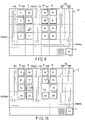
- FIGS. 9 to 12 are diagrams showing the transition of an exemplary rack sliding process in the transport control system according to the embodiment.
- the AGV controller 12 selects a single AGV 2 or multiple AGVs 2 from the AGVs 2 in the warehouse 61, and instructs the selected AGV 2 to perform the rack sliding.
- the processor 121 of the AGV controller 12 determines, based on the operational state of each AGV 2 in the warehouse 61, whether to have a single AGV 2 perform a rack retrieval and rack sliding, or to have multiple AGVs 2 (first and second transport vehicles) perform a rack retrieval and rack sliding.
- the processor 121 selects the same AGV 2 as the AGV 2 that transports the rack C1 in FIGS. 6 to 8 . If two different AGVs 2 (first and second transport vehicles) are slated to perform the rack retrieval and rack sliding, the processor 121 selects AGVs 2 that differ from the AGV 2 carrying the rack C1 in FIGS. 6 to 8 . Furthermore, if the rack sliding is performed multiple times, the processor 121 may determine, based on the operational state of each AGV 2 in the warehouse 61, whether to have the same AGV 2 perform the rack sliding multiple times, or to have different AGVs 2 perform the rack sliding multiple times, and then select AGVs 2.
- the rack sliding can be planned at the timing at which the rack retrieval is determined so that the rack sliding can be efficiently implemented.
- the AGV 2 for performing the rack sliding can be kept on standby near the vacant space before the vacant space is ready. In this manner, the rack sliding can be realized as soon as the vacant space is ready.
- the processor 121 of the AGV controller 12 outputs a second control signal to perform rack sliding once or multiple times, and the communication interface 125 thereby transmits the second control signal to the selected AGV 2.
- the second control signal includes a signal for performing rack sliding by the AGV 2 to carry the rack C2, which was adjacent to the rack C1, to the space 651 so that the vacancy in the space 651 created by the transport of the rack C1 can be shifted to the adjacent space 652 to create a vacant space 652.
- the selected AGV 2 travels based on the second control signal through the outbound passageway 631 and under-rack aisle 64, from the pickup station 62 to the pickup position corresponding to the rack C2 adjacent to the rack C1, where it lifts the rack C2 with the rack lifting mechanism 216, and completes the pickup of the rack C2.
- the AGV 2 transports the rack C2 from the pickup position to the space 651, and places the rack C2 in the space 651.
- the AGV 2 returns through the under-rack aisle 64 and return passageway 634 to the pickup station 62, and travels through the outbound passageway 631 and under-rack aisle 64 from the pickup station 62 to the pickup position corresponding to the rack C3 adjacent to the rack C2, where it lifts the rack C3 with the rack lifting mechanism 216, and completes the pickup of the rack C3.
- the AGV 2 transports the rack C3 from the space 653 to the space 652, and places the rack C3 in the space 652 (see FIG. 10 ).
- the AGV 2 travels through the under-rack aisle 64 from the space 651 to the space 653, lifts the rack C3 with the rack lifting mechanism 216, completes the pickup of the rack C3, transports the rack C3 from the space 653 to the space 652, and places the rack C3 in the space 652 (see FIG. 10 ).
- the AGV 2 also returns through the under-rack aisle 64 and return passageway 634 to the pickup station 62, and travels through the outbound passageway 631 and under-rack aisle 64 from the pickup station 62 to the pickup position corresponding to the rack C4 adjacent to the rack C3, where it lifts the rack C4 with the rack lifting mechanism 216, and completes the pickup of the rack C4.
- the AGV 2 transports the rack C4 from the space 654 to the space 653, and places the rack C4 in the space 653 (see FIG. 11 ).
- the AGV 2 travels through the under-rack aisle 64 from the space 652 to the space 654, lifts the rack C4 with the rack lifting mechanism 216, completes the pickup of the rack C4, transports the rack C4 from the space 654 to the space 653, and places the rack C4 in the space 653 (see FIG. 11 ).
- the vacancy in the space 651 can be shifted over to a targeted position (i.e., the rack row 511 of the rack group 51 closest to the pickup station 62) .
- the AGV 2 travels through the under-rack aisle 64 and return passageway 634 to the pickup position corresponding to the rack C1 of the pickup station 62, where it lifts the rack C1 with the rack lifting mechanism 216 and completes the pickup of the rack C1.
- the AGV 2 transports the rack C1 from the pickup position to the space 654 through the outbound passageway 631, and places the rack C1 in the space 654 (see FIG. 12 ).
- the retrieved rack C1 can be replaced in the rack row 511 of the rack group 51 closest to the pickup station 62.
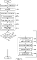
- FIG. 13 is a flowchart showing exemplary rack retrieving and rack sliding operations in the transport control system according to the embodiment.
- the host server 11 designates a targeted rack to be retrieved from groups of racks, and the communication interface 125 of the AGV controller 12 receives the designation of the targeted rack (ST1).
- the processor 121 selects one or more AGVs 2 slated to control the transport of a rack and sliding of the rack (ST2), and generates a first control signal for controlling the transport of a rack and a second control signal for controlling the sliding of the rack.
- the communication interface 125 transmits the first control signal to the selected AGV 2, and transmits the second control signal to the selected AGV 2.
- the AGVs 2 to which the first and second control signals are transmitted may be the same AGV 2, or different AGVs 2.
- the processor 121 of the AGV controller 12 transmits the first control signal to the selected AGV 2 via the communication interface 125 to control the transport of the rack (ST3), and transmits the second control signal to the selected AGV 2 via the communication interface 125 to control the rack sliding (ST5).
- the processor 121 controls the travel of the AGV 2 to a targeted rack with the first control signal (ST31), controls the pickup of the targeted rack by the AGV 2 (ST32), controls the travel of the AGV 2 toward the pickup station 62 (ST33), and controls the placement of the targeted rack in the pickup station 62 by the AGV 2 (ST34).
- the processor 121 controls the travel of the AGV 2 toward a sliding-targeted rack, which is adjacent to the transported rack, using the second control signal (ST51), the pickup of the sliding-targeted rack by the AGV 2 (ST52), the travel of the AGV 2 toward the vacant space (ST53), and the placement of the sliding-targeted rack in the vacant space by the AGV 2 (ST54).
- the rack sliding is repeated (ST5). If the targeted position becomes vacant (yes at ST4), the processing is terminated.
- the embodiment offers the transport control device, transport control method, and program, which can improve efficiency in storing, retrieving and replacing objects.
- racks By suitably laying out the outer aisles 63, racks can be placed at high density, allowing for effective use of the warehouse space.
- one-way traffic e.g., counterclockwise traffic
- AGVs 2 may be adopted for AGVs 2 to enhance the efficiency of rack retrieval.
- rack sliding a vacant space can be created in the rack row 511 of the rack group 51 closest to the pickup station 62, and the rack carried to the pickup station 62 can be efficiently returned to the rack group 51.
Landscapes
- Engineering & Computer Science (AREA)
- Physics & Mathematics (AREA)
- General Physics & Mathematics (AREA)
- Automation & Control Theory (AREA)
- Aviation & Aerospace Engineering (AREA)
- Radar, Positioning & Navigation (AREA)
- Remote Sensing (AREA)
- Mechanical Engineering (AREA)
- General Engineering & Computer Science (AREA)
- Manufacturing & Machinery (AREA)
- Quality & Reliability (AREA)
- Warehouses Or Storage Devices (AREA)
Abstract
Description
- Embodiments described herein relate generally to a transport control device, a transport control method, and a program.
- Recently, as the volume of objects such as cargo handled at distribution centers increases in the field of logistics, diligence is being made for greater efficiency in various approaches in relation to sorting and transporting of objects. As one approach, automated guided vehicles have been introduced to transport objects without requiring manpower. For instance, an automated guided vehicle ducks under a rack in which objects are contained, lifts the rack, and transports the rack to a targeted location.
- Patent Literature 1: Jpn. Pat. Appln. KOKAI Publication No.
2012-197184 - As a volume of objects to be handled increases, the storage space for racks that store objects needs to be expanded, which increases costs. Aligning the racks at high density may be one solution; however, if the racks are simply placed with no space in-between, there may be a difficulty in retrieving a rack from the back or middle of the aligned rack group. Moreover, once the rack is retrieved, it may also become difficult to return it to the place. There is a demand from business operators for increasing the efficiency of storing, retrieving, and replacing objects.
- The purpose of the embodiments is to offer a transport control device, a transport control method and program for improving efficiency in storing, retrieving and replacing objects.
- An information processing apparatus according to an embodiment includes a second recognition unit, an information processing unit, and an information output unit. The second recognition unit recognizes, by second recognition processing, a destination of an article with the destination not recognized by first recognition processing by a first recognition unit. The information processing unit generates recognition processing information proving that the second recognition processing has been executed by the second recognition unit. The information output unit outputs the recognition processing information. Each of the rack groups includes a first rack row and a second rack row. The outer aisle includes an outbound passageway, a first return passageway, and a second return passageway, the outbound passageway and the first return passageway being in proximity to the first rack row in a predetermined rack group of the rack groups, and the second return passageway being in proximity to the second rack row of each of the rack groups. The control unit outputs a first control signal for controlling a travel of the transport vehicle toward a first pickup position corresponding to a first rack included in the rack group, controlling a pickup of the first rack by the transport vehicle, and controlling the travel of the transport vehicle by way of the first or second return passageway from the first pickup position to the rack area. The control unit further outputs a second control signal for performing rack sliding once or a plurality of times, wherein in the rack sliding, a second rack previously adjacent to the first rack is transported by the transport vehicle to a vacant space created after transport of the first rack.
-
-
FIG. 1 is a diagram for schematically showing an exemplary configuration of a transport control system according to an embodiment. -
FIG. 2 is a diagram for showing an example of an AGV and a rack transported by the AGV in the transport control system according to the embodiment. -
FIG. 3 is a block diagram for schematically showing an exemplary configuration of an AGV controller in the transport control system according to the embodiment. -
FIG. 4 is a block diagram for schematically showing an exemplary configuration of an AGV according to the embodiment. -
FIG. 5 is a diagram for showing an exemplary warehouse environment for which the transport control system according to the embodiment is adopted. -
FIG. 6 is a transition diagram for showing an example of a rack retrieval by the AGV controller and AGV in the transport control system according to the embodiment. -
FIG. 7 is a transition diagram for showing an example of a rack retrieval by the AGV controller and AGV in the transport control system according to the embodiment. -
FIG. 8 is a transition diagram for showing an example of a rack retrieval by the AGV controller and AGV in the transport control system according to the embodiment. -
FIG. 9 is a transition diagram for showing an example of rack sliding by the AGV controller and AGV in the transport control system according to the embodiment. -
FIG. 10 is a transition diagram for showing an example of rack sliding by the AGV controller and AGV in the transport control system according to the embodiment. -
FIG. 11 is a transition diagram for showing an example of rack sliding by the AGV controller and AGV in the transport control system according to the embodiment. -
FIG. 12 is a transition diagram for showing an example of rack sliding by the AGV controller and AGV in the transport control system according to the embodiment. -
FIG. 13 is a flowchart for showing an example of rack retrieving and rack sliding by the AGV controller in the transport control system according to the embodiment. - Hereinafter, the embodiment will be described with reference to the drawings.
-
FIG. 1 is a diagram for schematically showing an exemplary configuration of a transport control system according to an embodiment. - As illustrated in
FIG. 1 , thetransport control system 1 includes ahost server 11 and an automated guided vehicle (AGV)controller 12 corresponding to a transport control device, where theAGV controller 12 controls anAGV 2, which corresponds to a transport vehicle. In this embodiment, theAGV controller 12 controlsmultiple AGVs 2. If the warehouse has multiple floors, anAGV controller 12 may be provided for a respective floor so that theAGV controller 12 of each floor can control theAGVs 2 allocated for the floor. - The
host server 11 can be realized by a single computer or by combining multiple computers. Thehost server 11 can communicate with other devices such as theAGV controller 12 in a wired or wireless manner, receive information from these devices or transmit a control signal or the like to the devices to control the devices. Thehost server 11 stores load information relating to objects such as loads, rack information relating to a rack containing one or more objects, AGV information relating to theAGVs 2, map data of the warehouse, and the like. The object information includes object identification information (ID) and the like, where each object has an object ID assigned. The rack information includes rack IDs and the like, where each rack has a rack ID assigned. The AGV information includes AGV IDs and the like, where eachAGV 2 has an AGV ID assigned. - An object ID may be marked directly upon each object, or a tag on which an object ID is marked may be attached to each object. As a manner of marking the object ID, it may be printed visibly, or printed invisibly with an ink that absorbs infrared light. Alternatively, an electronic tag or wireless tag in which an object ID is stored may be attached to an object. An object ID includes at least identification information constituted by one selected from numerals, characters, symbols, a bar code, a two-dimensional code, and a QR code (trademark), or a combination of two or more selected therefrom. Similarly, a rack ID may be marked directly upon each rack, or a tag or the like on which a rack ID is marked may be attached to the rack. An AGV 2 has an AGV ID. The AGV ID may be marked directly on each
AGV 2, or a tag or the like on which an AGV ID is marked may be attached to theAGV 2. - The
transport control system 1 according to the embodiment includes a plurality of cameras for taking images inside the warehouse and a plurality of ID readers. The ID readers read object IDs, rack IDs, and AGV IDs. Thehost server 11 detects the position of each object, each rack and eachAGV 2, and traces the move thereof, based on the warehouse map data, positional information of each camera and each ID reader on the map, an image taken by each camera, and an ID read by each ID reader. Thehost server 11 further draws up schedules regarding whichAGV 2 moves which rack at which timing, in response to an object retrieval request. - In accordance with the schedule received from the
host server 11, theAGV controller 12 transmits a control signal to eachAGV 2 to control the travel of eachAGV 2 and pickup and placement of a rack by theAGV 2. Pickup of a rack includes lifting, retrieving, and loading a rack. Placement of a rack includes lowering a lifted rack, releasing a retrieved rack, and dropping a loaded rack off. In the embodiment, a case of theAGV 2 picking up and moving a rack will be discussed. The transport control system according to the present embodiment is equally applicable to a case of theAGV 2 picking up and moving an object. -
FIG. 2 is a diagram for showing an example of an AGV and a rack to be transported by the AGV in the transport control system according to the embodiment. - An
AGV 2 is a wheeled, self-propelled robot, which, in response to a control signal from theAGV controller 12, travels toward a pickup position corresponding to a targeted rack R (e.g., directly under the rack R), picks up the targeted rack R at the pickup position, and travels toward a rack placement position. In response to the control signal from theAGV controller 12, theAGV 2 places the targeted rack R at the rack placement position corresponding to the targeted rack. - A rack R may stand upright with its four legs, with a height of the clearance under the rack (from the floor surface to the bottom of the rack) being larger than the height of an
AGV 2. This allows theAGV 2 to duck under the rack. TheAGV 2 that has ducked under the rack lifts the rack with therack lifting mechanism 216 to the extent that the legs will be lifted several centimeters off the floor surface, and travels with the rack being lifted. In this manner, theAGV 2 can transport the rack. - For instance, the
AGV 2 travels to the destination position, based on the map data, destination position data, and current position data. TheAGV 2 travels to the destination position while detecting the moving distance and moving direction. Alternatively, theAGV 2 travels to the destination position while reading a magnetic tape or two-dimensional bar codes attached to the passageways. Furthermore, theAGV 2 may be provided with a laser detection sensor, a camera or the like to detect obstacles (including other AGVs 2) so as to travel while avoiding the obstacles detected by the laser detection sensor or the obstacles detected through analysis of images taken by the camera. -
FIG. 3 is a block diagram for schematically showing an exemplary configuration of an AGV controller in the transport control system according to the embodiment. - The
AGV controller 12 corresponds to a transport control device configured to control the travel of theAGV 2 and pickup and placement of a rack by theAGV 2. For instance, theAGV controller 12 controls the operations of theAGV 2 including traveling to the rack pickup position, picking the rack up, moving the rack to the rack placement position, and dropping the rack off at the rack placement position. As illustrated inFIG. 3 , theAGV controller 12 includes aprocessor 121, aROM 122, aRAM 123, anauxiliary memory device 124, acommunication interface 125, and an input/output unit 126. - The
processor 121 serves as the central portion of the computer configured to execute processing such as calculations and controls required for the travel of theAGVs 2 and the pickup and placement of racks by theAGVs 2. Theprocessor 121 executes control to implement various functions of theAGV controller 12, based on the system software programs, application software programs, firmware programs stored in theROM 122,auxiliary memory device 124 or the like. Theprocessor 121 may be a central processing unit (CPU), a micro processing unit (MPU), or a digital signal processor (DSP). Alternatively, theprocessor 121 may be a combination of any of these. - The
ROM 122 is a non-transitory computer-readable storage medium, serving as the main memory device of the computer having theprocessor 121 as the central unit. TheROM 122 is a nonvolatile memory exclusively used for data reading. TheROM 122 stores therein the above-mentioned programs. Furthermore, theROM 122 stores data and various setting values used by theprocessor 121 for performing various kinds of processing. - The
RAM 123 serves as the main memory device of the computer having theprocessor 121 as the central unit. TheRAM 123 is a memory used for data reading and writing. TheRAM 123 is used, for example, as what is called a work area to temporarily store data when theprocessor 121 performs various kinds of processing. - The
auxiliary memory device 124 is a non-transitory computer-readable storage medium, serving as an auxiliary memory device of the computer having theprocessor 121 as the central unit. Theauxiliary memory device 124 may store therein the above-mentioned programs. Theauxiliary memory device 124 also stores the data used when theprocessor 121 performs various kinds of processing, as well as the data and various setting values produced through the processing of theprocessor 121. - The programs stored in the
ROM 122 orauxiliary memory device 124 include a program for controlling the travel of theAGVs 2 and pickup and placement of racks by theAGVs 2. For instance, theAGV controller 12 may be transferred to a manager of theAGV controller 12 or the like with the programs stored in theROM 122 orauxiliary memory device 124. Alternatively, theAGV controller 12 may also be transferred to the manager or the like with the programs not stored in theROM 122 orauxiliary memory device 124. The programs may be separately transferred to the manager so that they can be written into theauxiliary memory device 124 under the manipulation of the manager or a service provider. The transfer of the programs may be realized, for example, through a removable storage medium such as a magnetic disk, a magneto-optical disk, an optical disk, or a semiconductor memory, or through downloading via a network or the like. - The
communication interface 125 communicates via a network or the like with other devices such as thehost server 11 andAGVs 2 in a wired or wireless manner, receives various kinds of information transmitted from these devices, and transmits various kinds of information to the devices. For instance, thecommunication interface 125 receives a schedule from thehost server 11, and transmits to the AGVs 2 a control signal for controlling the travel of the AGVs. - The input/
output unit 126 includes a keyboard, a numeric keyboard, a mouse, a touch panel display, and the like. The input/output unit 126 receives an instruction input by the operator, and informs theprocessor 121 of the instructions. The touch panel display presents to the operator various types of information. -
FIG. 4 is a block diagram for schematically showing an exemplary configuration of an AGV according to the embodiment. - As illustrated in
FIG. 4 , theAGV 2 includes aprocessor 21, aROM 22, aRAM 23, anauxiliary memory device 24, acommunication interface 25, and a drivingunit 26. - The
processor 21 serves as the central portion of the computer configured to execute processing such as calculations and controls required for travel and pickup/drop-off of racks. Theprocessor 21 executes control to implement various functions of theAGV 2, based on the system software programs, application software programs, and firmware programs stored in theROM 22,auxiliary memory device 24 or the like. Theprocessor 21 may be a CPU, MPU, or DSP. Alternatively, theprocessor 21 may be a combination of any of these. For instance, theAGV controller 12 transmits a control signal for moving theAGV 2 to a destination position, and theprocessor 21 outputs a drive signal corresponding to map data included in the control signal transmitted from theAGV controller 12, destination position data, and current position data. Alternatively, theprocessor 21 outputs a drive signal corresponding to a rack pickup and drop-off instruction included in the control signal transmitted from theAGV controller 12. - The
ROM 22 is a non-transitory computer-readable storage medium, serving as the main memory device of the computer having theprocessor 21 as the central unit. TheROM 22 is a nonvolatile memory exclusively used for data reading. TheROM 22 stores therein the above-mentioned programs. Furthermore, theROM 22 stores data and various setting values used by theprocessor 21 for performing various kinds of processing. - The
RAM 23 serves as the main memory device of the computer having theprocessor 21 as the central unit. TheRAM 23 is a memory used for data reading and writing. TheRAM 23 is used, for example, as what is called a work area to temporarily store data when theprocessor 21 performs various kinds of processing. - The
auxiliary memory device 24 is a non-transitory computer-readable storage medium, serving as an auxiliary memory device of the computer having theprocessor 21 as the central unit. Theauxiliary memory device 24 may store therein the above-mentioned programs. Theauxiliary memory device 24 also stores the data used when theprocessor 21 performs various kinds of processing, as well as data and various setting values produced through the processing of theprocessor 21. - The
communication interface 25 communicates via a network or the like with other devices such as the AGV controller in a wireless manner, receives various types of information transmitted from these devices, and transmits various types of information to the devices. For instance, thecommunication interface 25 receives a control signal from theAGV controller 12. Thecommunication interface 25 also transmits completion notices to theAGV controller 12 to report the completion of travel to the destination position, completion of a pickup of a rack, or completion of a placement of a rack. - The driving
unit 26 includes wheels configured to be rotated by a motor, a steering mechanism for switching the traveling direction, a rack lifting mechanism configured to be vertically moved by a motor, and the like. In response to a drive signal output by theprocessor 21, the drivingunit 26 rotates or stops the motor and controls the steering mechanism to move theAGV 2 to a destination position. With theAGV 2 ducking under the rack, the drivingunit 26 rotates the motor (for a forward rotation) in response to a drive signal output by theprocessor 21 so that the rack lifting mechanism can ascend and lift the rack. After theAGV 2 reaches the destination position, the drivingunit 26 rotates the motor (for an inverse rotation) in response to a drive signal output by theprocessor 21 so that the rack lifting mechanism can descend and place the rack down to the floor. - Next, the environment of the warehouse in which the
AGVs 2 travels around will be described. -
FIG. 5 is a diagram for showing an exemplary warehouse environment for which the transport control system according to the embodiment is adopted. - In the warehouse, a plurality of racks are aligned. A plurality of aligned racks form a row of racks, and a plurality of rows of racks form a group of racks. Groups of racks that are formed are positioned at predetermined intervals, and racks in one group are aligned at predetermined intervals.
- For instance, as illustrated in
FIG. 5 ,rack groups warehouse 61. Therack group 51 includesrack rows rack row 511 includes racks A4, B4, C4, and D4, and therack row 512 includes racks A3, B3, C3, and D3. Furthermore, therack group 52 includesrack rows rack row 521 includes racks A2, B2, C2, and D2, and therack row 522 includes racks A1, B1, C1, and D1. A rack that can be any rack will be referred to as a "rack R". - The
warehouse 61 includes anouter aisle 63 at the peripheries of therack groups rack aisles 64 under the racks R, and a pickup station 62 (rack area) where a rack R carried from therack groups AGV 2 is placed. Under each rack R, an under-rack aisle 64 is formed to allow theAGV 2 to pass. - The
outer aisle 63 includes anoutbound passageway 631, a return passageway 632 (first return passageway), a return passageway 633 (second return passageway), a return passageway 634 (second return passageway), and a return passageway 635 (second return passageway), each having a passageway width corresponding to a rack transported by anAGV 2. - The
outbound passageway 631 is defined in the proximity of the rack row 511 (first rack row) of the rack group 51 (specific rack group), and theAGV 2 travels through thisoutbound passageway 631 from thepickup station 62 to a targeted rack R, which is included in therack row 511 of the rack group 51 (outbound trip). TheAGV 2 also travels through theoutbound passageway 631 and under-rack aisle 64 from thepickup station 62 to a targeted rack R included in therack row 512 of therack group 51 or to a targeted rack R included in therack row 521 orrack row 522 of the rack group 52 (outbound trip). Thereturn passageway 632 is defined in the proximity of the rack row 511 (first rack row) of the rack group 51 (specific rack group), and theAGV 2 travels through thisreturn passageway 632 from the targeted rack included in therack row 511 to the pickup station 62 (return trip). - The
return passageway 633 is defined in the proximity of the rack row 512 (second rack row) of therack group 51, and theAGV 2 travels through thisreturn passageway 633 and thereturn passageway 635 from the targeted rack included in therack row 512 to the pickup station 62 (return trip). Thereturn passageway 634 is defined in the proximity of the rack row 522 (second rack row) of therack group 52, and theAGV 2 travels through thisreturn passageway 634 and thereturn passageway 635 from the targeted rack included in therack row 522 to the pickup station 62 (return trip). As described above, all of theouter aisles 63 are determined to have one-way traffic in order to avoid collisions ofAGVs 2 and to simplify the transport management of themultiple AGVs 2. In addition, waiting of anAGV 2 for another AGV to pass can be reduced. - The
auxiliary memory device 124 of theAGV controller 12 stores the map data of thewarehouse 61, where the map data includes positional information relating to the racks R of therack groups pickup station 62,outer aisles 63, and under-rack aisles 64. Theauxiliary memory device 124 further stores management information for managing the racks R and objects contained in each rack R. The management information includes rack information including rack IDs and object information including object IDs. - Next, rack retrieval and rack sliding by the transport control system according to the embodiment will be described.
- For instance, the
AGV controller 12 selects one ormore AGVs 2 frommultiple AGVs 2 in thewarehouse 61. If oneAGV 2 is selected, theAGV controller 12 transmits to the selected AGV 2 a first control signal including a rack retrieval instruction, a second control signal including a rack sliding instruction, and a third control signal including a rack returning instruction for returning the rack placed in thepickup station 62 to a vacant space. Ifmultiple AGVs 2 are selected, theAGV controller 12 transmits the first control signal to one of the selectedAGVs 2, and the second control signal to another one of the selectedAGVs 2. - First, by referring to
FIGS. 6 to 8 , a rack retrieval will be described.FIGS. 6 to 8 are diagrams showing the transition of an exemplary rack retrieval by the transport control system according to the embodiment. - As illustrated in
FIG. 6 , it is assumed that therack groups AGV controller 12 selects asingle AGV 2 frommultiple AGVs 2 in thewarehouse 61, and instructs the selectedAGV 2 to retrieve the rack C1. For instance, theprocessor 121 of theAGV controller 12 selects anAGV 2 on standby in thepickup station 62 and outputs a first control signal, and thereby thecommunication interface 125 transmits the first control signal to the selectedAGV 2. - The first control signal controls the travel of the
AGV 2 through theoutbound passageway 631 and under-rack aisle 64 from thepickup station 62 to the pickup position corresponding to the rack C1 (e.g., directly below the rack C1), controls the pickup of the rack C1 by theAGV 2, controls the travel of theAGV 2 through the under-rack aisle 64,return passageway 634, and returnpassageway 635 from the pickup position corresponding to the rack C1 to the predetermined position of thepickup station 62, and controls the placement of the rack C1 at the predetermined position by theAGV 2. - In accordance with the first control signal, the
AGV 2 travels from thepickup station 62 to the pickup position corresponding to the rack C1 through the outbound passageway 631 (3 cells upward) and under-rack aisle 64 (5 cells leftward), where it lifts the rack C1 with therack lifting mechanism 216, and completes the pickup of the rack C1. Furthermore, as illustrated inFIGS. 7 and 8 , in accordance with the first control signal, theAGV 2 travels from the pickup position corresponding to the rack C1 to the predetermined position of thepickup station 62 through the under-rack aisle 64 (1 cell leftward), the return passageway 634 (2 cells downward), and the return passageway 635 (7 cells rightward and 1 cell downward), where it places the rack C1 at the predetermined position. As shown inFIGS. 7 and 8 , thespace 651 where the rack C1 of therack group 52 was placed becomes a vacant space, created by the transport of the rack C1. - With reference to
FIGS. 9 to 12 , the rack sliding will now be described.FIGS. 9 to 12 are diagrams showing the transition of an exemplary rack sliding process in the transport control system according to the embodiment. - The
AGV controller 12 selects asingle AGV 2 ormultiple AGVs 2 from theAGVs 2 in thewarehouse 61, and instructs the selectedAGV 2 to perform the rack sliding. Theprocessor 121 of theAGV controller 12 determines, based on the operational state of eachAGV 2 in thewarehouse 61, whether to have asingle AGV 2 perform a rack retrieval and rack sliding, or to have multiple AGVs 2 (first and second transport vehicles) perform a rack retrieval and rack sliding. - If a single AGV 2 (first transport vehicle) is slated to perform the rack retrieval and rack sliding, the
processor 121 selects thesame AGV 2 as theAGV 2 that transports the rack C1 inFIGS. 6 to 8 . If two different AGVs 2 (first and second transport vehicles) are slated to perform the rack retrieval and rack sliding, theprocessor 121 selectsAGVs 2 that differ from theAGV 2 carrying the rack C1 inFIGS. 6 to 8 . Furthermore, if the rack sliding is performed multiple times, theprocessor 121 may determine, based on the operational state of eachAGV 2 in thewarehouse 61, whether to have thesame AGV 2 perform the rack sliding multiple times, or to havedifferent AGVs 2 perform the rack sliding multiple times, and then selectAGVs 2. - When
multiple AGVs 2 are selected, the rack sliding can be planned at the timing at which the rack retrieval is determined so that the rack sliding can be efficiently implemented. TheAGV 2 for performing the rack sliding can be kept on standby near the vacant space before the vacant space is ready. In this manner, the rack sliding can be realized as soon as the vacant space is ready. - The
processor 121 of theAGV controller 12 outputs a second control signal to perform rack sliding once or multiple times, and thecommunication interface 125 thereby transmits the second control signal to the selectedAGV 2. For instance, the second control signal includes a signal for performing rack sliding by theAGV 2 to carry the rack C2, which was adjacent to the rack C1, to thespace 651 so that the vacancy in thespace 651 created by the transport of the rack C1 can be shifted to theadjacent space 652 to create avacant space 652. - If a
single AGV 2 on standby in thepickup station 62 is selected, the selectedAGV 2 travels based on the second control signal through theoutbound passageway 631 and under-rack aisle 64, from thepickup station 62 to the pickup position corresponding to the rack C2 adjacent to the rack C1, where it lifts the rack C2 with therack lifting mechanism 216, and completes the pickup of the rack C2. As illustrated inFIG. 9 , theAGV 2 transports the rack C2 from the pickup position to thespace 651, and places the rack C2 in thespace 651. - Furthermore, in accordance with the second control signal, the
AGV 2 returns through the under-rack aisle 64 andreturn passageway 634 to thepickup station 62, and travels through theoutbound passageway 631 and under-rack aisle 64 from thepickup station 62 to the pickup position corresponding to the rack C3 adjacent to the rack C2, where it lifts the rack C3 with therack lifting mechanism 216, and completes the pickup of the rack C3. TheAGV 2 transports the rack C3 from thespace 653 to thespace 652, and places the rack C3 in the space 652 (seeFIG. 10 ). Alternatively, in accordance with the second control signal, theAGV 2 travels through the under-rack aisle 64 from thespace 651 to thespace 653, lifts the rack C3 with therack lifting mechanism 216, completes the pickup of the rack C3, transports the rack C3 from thespace 653 to thespace 652, and places the rack C3 in the space 652 (seeFIG. 10 ). - In accordance with the second control signal, the
AGV 2 also returns through the under-rack aisle 64 andreturn passageway 634 to thepickup station 62, and travels through theoutbound passageway 631 and under-rack aisle 64 from thepickup station 62 to the pickup position corresponding to the rack C4 adjacent to the rack C3, where it lifts the rack C4 with therack lifting mechanism 216, and completes the pickup of the rack C4. TheAGV 2 transports the rack C4 from thespace 654 to thespace 653, and places the rack C4 in the space 653 (seeFIG. 11 ). Alternatively, in accordance with the second control signal, theAGV 2 travels through the under-rack aisle 64 from thespace 652 to thespace 654, lifts the rack C4 with therack lifting mechanism 216, completes the pickup of the rack C4, transports the rack C4 from thespace 654 to thespace 653, and places the rack C4 in the space 653 (seeFIG. 11 ). In the above manner, the vacancy in thespace 651 can be shifted over to a targeted position (i.e., therack row 511 of therack group 51 closest to the pickup station 62) . - In accordance with the third control signal, the
AGV 2 travels through the under-rack aisle 64 andreturn passageway 634 to the pickup position corresponding to the rack C1 of thepickup station 62, where it lifts the rack C1 with therack lifting mechanism 216 and completes the pickup of the rack C1. TheAGV 2 transports the rack C1 from the pickup position to thespace 654 through theoutbound passageway 631, and places the rack C1 in the space 654 (seeFIG. 12 ). In the above manner, the retrieved rack C1 can be replaced in therack row 511 of therack group 51 closest to thepickup station 62. -
FIG. 13 is a flowchart showing exemplary rack retrieving and rack sliding operations in the transport control system according to the embodiment. - For instance, the
host server 11 designates a targeted rack to be retrieved from groups of racks, and thecommunication interface 125 of theAGV controller 12 receives the designation of the targeted rack (ST1). Based on the operational states of theAGVs 2, theprocessor 121 selects one ormore AGVs 2 slated to control the transport of a rack and sliding of the rack (ST2), and generates a first control signal for controlling the transport of a rack and a second control signal for controlling the sliding of the rack. Thecommunication interface 125 transmits the first control signal to the selectedAGV 2, and transmits the second control signal to the selectedAGV 2. TheAGVs 2 to which the first and second control signals are transmitted may be thesame AGV 2, ordifferent AGVs 2. - The
processor 121 of theAGV controller 12 transmits the first control signal to the selectedAGV 2 via thecommunication interface 125 to control the transport of the rack (ST3), and transmits the second control signal to the selectedAGV 2 via thecommunication interface 125 to control the rack sliding (ST5). - That is, the
processor 121 controls the travel of theAGV 2 to a targeted rack with the first control signal (ST31), controls the pickup of the targeted rack by the AGV 2 (ST32), controls the travel of theAGV 2 toward the pickup station 62 (ST33), and controls the placement of the targeted rack in thepickup station 62 by the AGV 2 (ST34). - If the targeted position (e.g., the
rack row 511 of therack group 51 closest to the pickup station 62) does not become vacant under the control of the rack transport at ST3 (no at ST4), theprocessor 121 controls the travel of theAGV 2 toward a sliding-targeted rack, which is adjacent to the transported rack, using the second control signal (ST51), the pickup of the sliding-targeted rack by the AGV 2 (ST52), the travel of theAGV 2 toward the vacant space (ST53), and the placement of the sliding-targeted rack in the vacant space by the AGV 2 (ST54). - If the targeted position does not become vacant (no at ST4), the rack sliding is repeated (ST5). If the targeted position becomes vacant (yes at ST4), the processing is terminated.
- As described above, the embodiment offers the transport control device, transport control method, and program, which can improve efficiency in storing, retrieving and replacing objects.
- By suitably laying out the
outer aisles 63, racks can be placed at high density, allowing for effective use of the warehouse space. When retrieving a rack, one-way traffic (e.g., counterclockwise traffic) may be adopted forAGVs 2 to enhance the efficiency of rack retrieval. Furthermore, with the rack sliding, a vacant space can be created in therack row 511 of therack group 51 closest to thepickup station 62, and the rack carried to thepickup station 62 can be efficiently returned to therack group 51. In addition, with rack sliding, less frequently used racks are gathered in the rack group 52 (and in the rack row 522) further away from thepickup station 62, while frequently used racks are gathered in the rack group 51 (and in the rack row 511) closer to thepickup station 62, which enhances the efficiency of rack retrieval. - While certain embodiments have been described, these embodiments have been presented by way of example only, and are not intended to limit the scope of the invention. These new embodiments can be implemented in various other forms. Various omissions, replacements, and changes can be made without departing from the spirit of the invention. The accompanying claims and their equivalents are intended to cover such forms or modifications as would fall within the scope and spirit of the inventions.
Claims (9)
- A transport control device comprising:a storage unit configured to store positional information relating to racks included in a plurality of rack groups provided at predetermined intervals, an outer aisle around the rack groups, an under-rack aisle under each of the racks, and a rack area in which a rack retrieved from the rack groups by a transport vehicle is placed, and management information for managing the racks;a control unit configured to output a control signal for controlling the transport vehicle based on the positional information and the management information; anda communication unit configured to transmit the control signal to the transport vehicle,wherein each of the rack groups includes a first rack row and a second rack row,the outer aisle includes an outbound passageway, a first return passageway, and a second return passageway, the outbound passageway and the first return passageway being in proximity to the first rack row in a predetermined rack group of the rack groups, and the second return passageway being in proximity to the second rack row of each of the rack groups,the control unit outputs a first control signal for controlling a travel of the transport vehicle toward a first pickup position corresponding to a first rack included in the rack group, controlling a pickup of the first rack by the transport vehicle, and controlling the travel of the transport vehicle by way of the first or second return passageway from the first pickup position to the rack area, andthe control unit further outputs a second control signal for performing rack sliding once or a plurality of times, wherein in the rack sliding, a second rack previously adjacent to the first rack is transported by the transport vehicle to a vacant space created after transport of the first rack.
- The transport control device according to claim 1, wherein
the second control signal includes a signal for controlling the travel of the transport vehicle toward a second pickup position corresponding to the second rack, controlling a pickup of the second rack by the transport vehicle, controlling the travel of the transport vehicle from the second pickup position to the first pickup position, and controlling a placement of the second rack at the first pickup position by the transport vehicle. - The transport control device according to claim 1 or 2, wherein
the second control signal includes a signal for repeating the rack sliding until the vacant space moves to a position included in the first rack row of the predetermined rack group. - The transport control device according to any one of claims 1 to 3, wherein
the predetermined rack group is a rack group closest to the rack area among the rack groups. - The transport control device according to claim 1, wherein
in the case where the transport vehicle is instructed to travel to the first rack included in the second rack row, the first control signal includes a signal for controlling the travel of the transport vehicle under an under-rack aisle under racks included in the first rack row. - The transport control device according to any one of claims 1 to 5, wherein
the communication unit transmits the first control signal to a first transport vehicle, and transmits the second control signal to a second transport vehicle. - The transport control device according to claim 3, wherein
the control unit outputs a third control signal for controlling the travel of the transport vehicle toward a third pickup position corresponding to the first rack in the rack area, controlling the pickup of the first rack by the transport vehicle, and controlling the travel of the transport vehicle by way of the outbound passageway from the third pickup position to the vacant space included in the predetermined rack group. - A transport control method, comprising:outputting a control signal for controlling a transport vehicle based on positional information relating to racks included in a plurality of rack groups provided at predetermined intervals, an outer aisle around the rack groups, an under-rack aisle under each of the racks, and a rack area in which a rack retrieved from the rack groups by the transport vehicle is placed, and management information for managing the racks; andtransmitting the control signal to the transport vehicle, whereineach of the rack groups includes a first rack row and a second rack row,the outer aisle includes an outbound passageway, a first return passageway, and a second return passageway, the outbound passageway and the first return passageway being in proximity to the first rack row in a predetermined rack group of the rack groups, and the second return passageway being in proximity to the second rack row of each of the rack groups, andthe method further comprises:outputting a first control signal for controlling a travel of the transport vehicle toward a first pickup position corresponding to a first rack included in the rack group, controlling a pickup of the first rack by the transport vehicle, and controlling the travel of the transport vehicle by way of the first or second return passageway from the first pickup position to the rack area, andoutputting a second control signal for performing rack sliding once or a plurality of times, wherein in the rack sliding a second rack previously adjacent to the first rack is transported by the transport vehicle to a vacant space created after transport of the first rack.
- A program for causing a computer to implement:outputting a control signal for controlling a transport vehicle based on positional information relating to racks included in a plurality of rack groups provided at predetermined intervals, an outer aisle around the rack groups, an under-rack aisle under each of the racks, and a rack area in which a rack retrieved from the rack groups by the transport vehicle is placed, and management information for managing the racks; andtransmitting the control signal to the transport vehicle, whereineach of the rack groups includes a first rack row and a second rack row,the outer aisle includes an outbound passageway, a first return passageway, and a second return passageway, the outbound passageway and the first return passageway being in proximity to the first rack row in a predetermined rack group of the rack groups, and the second return passageway being in proximity to the second rack row of each of the rack groups, andthe program causes the computer to further implement:outputting a first control signal for controlling a travel of the transport vehicle toward a first pickup position corresponding to a first rack included in the rack group, controlling a pickup of the first rack by the transport vehicle, and controlling the travel of the transport vehicle by way of the first or second return passageway from the first pickup position to the rack area, andoutputting a second control signal for performing rack sliding once or a plurality of times, wherein in the rack sliding a second rack previously adjacent to the first rack is transported by the transport vehicle to a vacant space created after transport of the first rack.
Applications Claiming Priority (2)
| Application Number | Priority Date | Filing Date | Title |
|---|---|---|---|
| JP2020034082A JP6736788B1 (en) | 2020-02-28 | 2020-02-28 | Transfer control device, transfer control method, and program |
| PCT/JP2021/006799 WO2021172335A1 (en) | 2020-02-28 | 2021-02-24 | Transport control device, transport control method, and program |
Publications (3)
| Publication Number | Publication Date |
|---|---|
| EP4112499A1 true EP4112499A1 (en) | 2023-01-04 |
| EP4112499A4 EP4112499A4 (en) | 2024-02-21 |
| EP4112499B1 EP4112499B1 (en) | 2025-04-30 |
Family
ID=71892442
Family Applications (1)
| Application Number | Title | Priority Date | Filing Date |
|---|---|---|---|
| EP21759990.1A Active EP4112499B1 (en) | 2020-02-28 | 2021-02-24 | Transport control device, transport control method, and program |
Country Status (5)
| Country | Link |
|---|---|
| US (1) | US20220402698A1 (en) |
| EP (1) | EP4112499B1 (en) |
| JP (1) | JP6736788B1 (en) |
| CN (1) | CN115210151B (en) |
| WO (1) | WO2021172335A1 (en) |
Families Citing this family (7)
| Publication number | Priority date | Publication date | Assignee | Title |
|---|---|---|---|---|
| JP6786743B1 (en) * | 2020-06-25 | 2020-11-18 | 和則 藤沢 | Picking support system and program |
| JP6933765B1 (en) * | 2020-09-23 | 2021-09-08 | 株式会社東芝 | Motion control device and motion control system |
| JP2023045443A (en) | 2021-09-22 | 2023-04-03 | 株式会社東芝 | Transportation plan generation method, transportation plan generation device, and program |
| JP7802479B2 (en) * | 2021-09-24 | 2026-01-20 | 株式会社東芝 | Shelf processing system and shelf transport control system |
| JP7715990B2 (en) * | 2021-10-26 | 2025-07-31 | 富士通株式会社 | Information processing device, work plan creation method, and work plan creation program |
| JP7756539B2 (en) * | 2021-10-28 | 2025-10-20 | 株式会社日立製作所 | Transport system and method |
| JP2023102068A (en) * | 2022-01-11 | 2023-07-24 | 株式会社東芝 | Program, information processing method and information processing apparatus |
Family Cites Families (15)
| Publication number | Priority date | Publication date | Assignee | Title |
|---|---|---|---|---|
| US7894933B2 (en) * | 2005-07-19 | 2011-02-22 | Kiva Systems, Inc. | Method and system for retrieving inventory items |
| US7912574B2 (en) | 2006-06-19 | 2011-03-22 | Kiva Systems, Inc. | System and method for transporting inventory items |
| DE202010016724U1 (en) * | 2010-09-29 | 2011-04-07 | Kht Kommissionier- Und Handhabungstechnik Gmbh | Device for storing and retrieving goods |
| DE102011053633A1 (en) * | 2011-09-15 | 2013-03-21 | Klug Gmbh Integrierte Systeme | System for storing and delivering transport units |
| US20140178161A1 (en) * | 2012-12-21 | 2014-06-26 | Mossburger Logistics Network & Development KG | Conveyor technology supported commissioning of articles |
| US8965562B1 (en) * | 2013-09-09 | 2015-02-24 | Amazon Technologies, Inc. | Efficient shuffling of mobile drive units for inventory holders |
| EP3056453A4 (en) * | 2013-10-11 | 2017-07-26 | Hitachi, Ltd. | Transport vehicle control device and transport vehicle control method |
| JP2015096993A (en) * | 2013-11-15 | 2015-05-21 | 株式会社日立製作所 | Transport management device, transport management method, and transport management program |
| JP6695653B2 (en) * | 2014-08-08 | 2020-05-20 | 株式会社ケンコントロールズ | Transfer planning method, transfer planning device, transfer system, computer program |
| US10022867B2 (en) * | 2014-11-11 | 2018-07-17 | X Development Llc | Dynamically maintaining a map of a fleet of robotic devices in an environment to facilitate robotic action |
| US9809384B2 (en) * | 2014-11-24 | 2017-11-07 | Amazon Technologies, Inc. | Inventory system with efficient operator handling of inventory items |
| KR102824771B1 (en) * | 2016-01-14 | 2025-06-25 | 크라운 이큅먼트 코포레이션 | Goods-to-people warehouses including multi-level racking, mobile storage units, storage unit transporters and pick-and-place vehicles |
| CN108698760B (en) * | 2016-04-27 | 2020-04-21 | 株式会社日立制作所 | Transportation system, transportation method, and management system |
| US10210212B2 (en) * | 2017-06-15 | 2019-02-19 | Sap Se | Dynamic layout management for robotics warehouse system |
| JP6827905B2 (en) * | 2017-10-26 | 2021-02-10 | 株式会社日立物流 | Shelf management system and shelf management method |
-
2020
- 2020-02-28 JP JP2020034082A patent/JP6736788B1/en active Active
-
2021
- 2021-02-24 WO PCT/JP2021/006799 patent/WO2021172335A1/en not_active Ceased
- 2021-02-24 EP EP21759990.1A patent/EP4112499B1/en active Active
- 2021-02-24 CN CN202180016874.4A patent/CN115210151B/en active Active
-
2022
- 2022-08-25 US US17/895,832 patent/US20220402698A1/en not_active Abandoned
Also Published As
| Publication number | Publication date |
|---|---|
| WO2021172335A1 (en) | 2021-09-02 |
| JP6736788B1 (en) | 2020-08-05 |
| CN115210151B (en) | 2024-06-11 |
| US20220402698A1 (en) | 2022-12-22 |
| EP4112499B1 (en) | 2025-04-30 |
| EP4112499A4 (en) | 2024-02-21 |
| JP2021134079A (en) | 2021-09-13 |
| CN115210151A (en) | 2022-10-18 |
Similar Documents
| Publication | Publication Date | Title |
|---|---|---|
| EP4112499A1 (en) | Transport control device, transport control method, and program | |
| US20240043213A1 (en) | Hybrid Modular Storage Fetching System | |
| CN109279252B (en) | Cargo picking system and method | |
| JP6829779B2 (en) | Warehouse management system and method | |
| US12441543B2 (en) | Predicting a path of material handling equipment and determining an obstacle-free path | |
| JP6220406B2 (en) | Picking system | |
| EP3851398A1 (en) | Warehouse storage access system and method | |
| CN214987861U (en) | Storage goods picking system | |
| KR102301520B1 (en) | Article picking system and article picking method | |
| WO2018129362A1 (en) | Hybrid modular storage fetching system | |
| EP4033315A1 (en) | Goods processing system and goods processing method | |
| KR20190048674A (en) | Intelligent logistics robot | |
| CN115345447A (en) | Task management method, electronic device and storage medium | |
| CN115367356A (en) | Warehousing system and management method, interaction method, server and client equipment thereof | |
| JP2023129905A (en) | Warehouse management system and pallet shaped parts | |
| JP2023129906A (en) | warehouse management system | |
| JP2023129904A (en) | warehouse management system | |
| HK40127505A (en) | Predicting a path of material handling equipment and determining an obstacle-free path | |
| CN116767733A (en) | Logistics storage management system based on unmanned forklift | |
| HK40053737A (en) | Cargo transport system and method |
Legal Events
| Date | Code | Title | Description |
|---|---|---|---|
| STAA | Information on the status of an ep patent application or granted ep patent |
Free format text: STATUS: THE INTERNATIONAL PUBLICATION HAS BEEN MADE |
|
| PUAI | Public reference made under article 153(3) epc to a published international application that has entered the european phase |
Free format text: ORIGINAL CODE: 0009012 |
|
| STAA | Information on the status of an ep patent application or granted ep patent |
Free format text: STATUS: REQUEST FOR EXAMINATION WAS MADE |
|
| 17P | Request for examination filed |
Effective date: 20220817 |
|
| AK | Designated contracting states |
Kind code of ref document: A1 Designated state(s): AL AT BE BG CH CY CZ DE DK EE ES FI FR GB GR HR HU IE IS IT LI LT LU LV MC MK MT NL NO PL PT RO RS SE SI SK SM TR |
|
| DAV | Request for validation of the european patent (deleted) | ||
| DAX | Request for extension of the european patent (deleted) | ||
| REG | Reference to a national code |
Free format text: PREVIOUS MAIN CLASS: B65G0001000000 Ref country code: DE Ref legal event code: R079 Ref document number: 602021030053 Country of ref document: DE Free format text: PREVIOUS MAIN CLASS: B65G0001000000 Ipc: G05D0001698000 |
|
| A4 | Supplementary search report drawn up and despatched |
Effective date: 20240119 |
|
| RIC1 | Information provided on ipc code assigned before grant |
Ipc: G05D 109/10 20240101ALI20240115BHEP Ipc: G05D 107/70 20240101ALI20240115BHEP Ipc: G05D 105/28 20240101ALI20240115BHEP Ipc: G06Q 10/087 20230101ALI20240115BHEP Ipc: G05B 19/418 20060101ALI20240115BHEP Ipc: G05D 1/249 20240101ALI20240115BHEP Ipc: G05D 1/246 20240101ALI20240115BHEP Ipc: B65G 1/137 20060101ALI20240115BHEP Ipc: B65G 1/10 20060101ALI20240115BHEP Ipc: G05D 1/698 20240101AFI20240115BHEP |
|
| GRAP | Despatch of communication of intention to grant a patent |
Free format text: ORIGINAL CODE: EPIDOSNIGR1 |
|
| STAA | Information on the status of an ep patent application or granted ep patent |
Free format text: STATUS: GRANT OF PATENT IS INTENDED |
|
| INTG | Intention to grant announced |
Effective date: 20250121 |
|
| GRAS | Grant fee paid |
Free format text: ORIGINAL CODE: EPIDOSNIGR3 |
|
| GRAA | (expected) grant |
Free format text: ORIGINAL CODE: 0009210 |
|
| STAA | Information on the status of an ep patent application or granted ep patent |
Free format text: STATUS: THE PATENT HAS BEEN GRANTED |
|
| AK | Designated contracting states |
Kind code of ref document: B1 Designated state(s): AL AT BE BG CH CY CZ DE DK EE ES FI FR GB GR HR HU IE IS IT LI LT LU LV MC MK MT NL NO PL PT RO RS SE SI SK SM TR |
|
| REG | Reference to a national code |
Ref country code: CH Ref legal event code: EP Ref country code: GB Ref legal event code: FG4D |
|
| REG | Reference to a national code |
Ref country code: DE Ref legal event code: R096 Ref document number: 602021030053 Country of ref document: DE |
|
| REG | Reference to a national code |
Ref country code: IE Ref legal event code: FG4D |
|
| REG | Reference to a national code |
Ref country code: DE Ref legal event code: R081 Ref document number: 602021030053 Country of ref document: DE Owner name: KABUSHIKI KAISHA TOSHIBA, JP Free format text: FORMER OWNERS: KABUSHIKI KAISHA TOSHIBA, TOKYO, JP; TOSHIBA INFRASTRUCTURE SYSTEMS & SOLUTIONS CORPORATION, KAWASAKI-SHI, KANAGAWA, JP |
|
| REG | Reference to a national code |
Ref country code: NL Ref legal event code: MP Effective date: 20250430 |
|
| REG | Reference to a national code |
Ref country code: AT Ref legal event code: MK05 Ref document number: 1790607 Country of ref document: AT Kind code of ref document: T Effective date: 20250430 |
|
| RAP2 | Party data changed (patent owner data changed or rights of a patent transferred) |
Owner name: KABUSHIKI KAISHA TOSHIBA |
|
| PG25 | Lapsed in a contracting state [announced via postgrant information from national office to epo] |
Ref country code: PT Free format text: LAPSE BECAUSE OF FAILURE TO SUBMIT A TRANSLATION OF THE DESCRIPTION OR TO PAY THE FEE WITHIN THE PRESCRIBED TIME-LIMIT Effective date: 20250901 Ref country code: FI Free format text: LAPSE BECAUSE OF FAILURE TO SUBMIT A TRANSLATION OF THE DESCRIPTION OR TO PAY THE FEE WITHIN THE PRESCRIBED TIME-LIMIT Effective date: 20250430 Ref country code: ES Free format text: LAPSE BECAUSE OF FAILURE TO SUBMIT A TRANSLATION OF THE DESCRIPTION OR TO PAY THE FEE WITHIN THE PRESCRIBED TIME-LIMIT Effective date: 20250430 |
|
| REG | Reference to a national code |
Ref country code: LT Ref legal event code: MG9D |
|
| PG25 | Lapsed in a contracting state [announced via postgrant information from national office to epo] |
Ref country code: GR Free format text: LAPSE BECAUSE OF FAILURE TO SUBMIT A TRANSLATION OF THE DESCRIPTION OR TO PAY THE FEE WITHIN THE PRESCRIBED TIME-LIMIT Effective date: 20250731 Ref country code: NO Free format text: LAPSE BECAUSE OF FAILURE TO SUBMIT A TRANSLATION OF THE DESCRIPTION OR TO PAY THE FEE WITHIN THE PRESCRIBED TIME-LIMIT Effective date: 20250730 |
|
| PG25 | Lapsed in a contracting state [announced via postgrant information from national office to epo] |
Ref country code: NL Free format text: LAPSE BECAUSE OF FAILURE TO SUBMIT A TRANSLATION OF THE DESCRIPTION OR TO PAY THE FEE WITHIN THE PRESCRIBED TIME-LIMIT Effective date: 20250430 Ref country code: PL Free format text: LAPSE BECAUSE OF FAILURE TO SUBMIT A TRANSLATION OF THE DESCRIPTION OR TO PAY THE FEE WITHIN THE PRESCRIBED TIME-LIMIT Effective date: 20250430 |
|
| PG25 | Lapsed in a contracting state [announced via postgrant information from national office to epo] |
Ref country code: BG Free format text: LAPSE BECAUSE OF FAILURE TO SUBMIT A TRANSLATION OF THE DESCRIPTION OR TO PAY THE FEE WITHIN THE PRESCRIBED TIME-LIMIT Effective date: 20250430 |
|
| PG25 | Lapsed in a contracting state [announced via postgrant information from national office to epo] |
Ref country code: HR Free format text: LAPSE BECAUSE OF FAILURE TO SUBMIT A TRANSLATION OF THE DESCRIPTION OR TO PAY THE FEE WITHIN THE PRESCRIBED TIME-LIMIT Effective date: 20250430 |
|
| PG25 | Lapsed in a contracting state [announced via postgrant information from national office to epo] |
Ref country code: AT Free format text: LAPSE BECAUSE OF FAILURE TO SUBMIT A TRANSLATION OF THE DESCRIPTION OR TO PAY THE FEE WITHIN THE PRESCRIBED TIME-LIMIT Effective date: 20250430 |
|
| PG25 | Lapsed in a contracting state [announced via postgrant information from national office to epo] |
Ref country code: RS Free format text: LAPSE BECAUSE OF FAILURE TO SUBMIT A TRANSLATION OF THE DESCRIPTION OR TO PAY THE FEE WITHIN THE PRESCRIBED TIME-LIMIT Effective date: 20250731 |
|
| PG25 | Lapsed in a contracting state [announced via postgrant information from national office to epo] |
Ref country code: IS Free format text: LAPSE BECAUSE OF FAILURE TO SUBMIT A TRANSLATION OF THE DESCRIPTION OR TO PAY THE FEE WITHIN THE PRESCRIBED TIME-LIMIT Effective date: 20250830 |
|
| PG25 | Lapsed in a contracting state [announced via postgrant information from national office to epo] |
Ref country code: LV Free format text: LAPSE BECAUSE OF FAILURE TO SUBMIT A TRANSLATION OF THE DESCRIPTION OR TO PAY THE FEE WITHIN THE PRESCRIBED TIME-LIMIT Effective date: 20250430 |
|
| PG25 | Lapsed in a contracting state [announced via postgrant information from national office to epo] |
Ref country code: SM Free format text: LAPSE BECAUSE OF FAILURE TO SUBMIT A TRANSLATION OF THE DESCRIPTION OR TO PAY THE FEE WITHIN THE PRESCRIBED TIME-LIMIT Effective date: 20250430 Ref country code: DK Free format text: LAPSE BECAUSE OF FAILURE TO SUBMIT A TRANSLATION OF THE DESCRIPTION OR TO PAY THE FEE WITHIN THE PRESCRIBED TIME-LIMIT Effective date: 20250430 |
|
| PG25 | Lapsed in a contracting state [announced via postgrant information from national office to epo] |
Ref country code: CZ Free format text: LAPSE BECAUSE OF FAILURE TO SUBMIT A TRANSLATION OF THE DESCRIPTION OR TO PAY THE FEE WITHIN THE PRESCRIBED TIME-LIMIT Effective date: 20250430 |
|
| PG25 | Lapsed in a contracting state [announced via postgrant information from national office to epo] |
Ref country code: EE Free format text: LAPSE BECAUSE OF FAILURE TO SUBMIT A TRANSLATION OF THE DESCRIPTION OR TO PAY THE FEE WITHIN THE PRESCRIBED TIME-LIMIT Effective date: 20250430 |
|
| PG25 | Lapsed in a contracting state [announced via postgrant information from national office to epo] |
Ref country code: SK Free format text: LAPSE BECAUSE OF FAILURE TO SUBMIT A TRANSLATION OF THE DESCRIPTION OR TO PAY THE FEE WITHIN THE PRESCRIBED TIME-LIMIT Effective date: 20250430 |
|
| PG25 | Lapsed in a contracting state [announced via postgrant information from national office to epo] |
Ref country code: IT Free format text: LAPSE BECAUSE OF FAILURE TO SUBMIT A TRANSLATION OF THE DESCRIPTION OR TO PAY THE FEE WITHIN THE PRESCRIBED TIME-LIMIT Effective date: 20250430 |
|
| REG | Reference to a national code |
Ref country code: DE Ref legal event code: R097 Ref document number: 602021030053 Country of ref document: DE |
|
| PLBE | No opposition filed within time limit |
Free format text: ORIGINAL CODE: 0009261 |
|
| STAA | Information on the status of an ep patent application or granted ep patent |
Free format text: STATUS: NO OPPOSITION FILED WITHIN TIME LIMIT |
|
| REG | Reference to a national code |
Ref country code: CH Ref legal event code: L10 Free format text: ST27 STATUS EVENT CODE: U-0-0-L10-L00 (AS PROVIDED BY THE NATIONAL OFFICE) Effective date: 20260311 |
|
| 26N | No opposition filed |
Effective date: 20260202 |
|
| PGFP | Annual fee paid to national office [announced via postgrant information from national office to epo] |
Ref country code: DE Payment date: 20260102 Year of fee payment: 6 |