EP4112399B1 - Twin chamber air dryer and pneumatic system - Google Patents
Twin chamber air dryer and pneumatic system Download PDFInfo
- Publication number
- EP4112399B1 EP4112399B1 EP21181963.6A EP21181963A EP4112399B1 EP 4112399 B1 EP4112399 B1 EP 4112399B1 EP 21181963 A EP21181963 A EP 21181963A EP 4112399 B1 EP4112399 B1 EP 4112399B1
- Authority
- EP
- European Patent Office
- Prior art keywords
- valve
- regeneration
- air dryer
- pneumatic
- chamber air
- Prior art date
- Legal status (The legal status is an assumption and is not a legal conclusion. Google has not performed a legal analysis and makes no representation as to the accuracy of the status listed.)
- Active
Links
- 239000002274 desiccant Substances 0.000 claims description 65
- 230000008929 regeneration Effects 0.000 claims description 59
- 238000011069 regeneration method Methods 0.000 claims description 59
- 238000010926 purge Methods 0.000 claims description 26
- 230000000903 blocking effect Effects 0.000 claims description 12
- 230000003584 silencer Effects 0.000 claims description 4
- 230000008014 freezing Effects 0.000 claims description 2
- 238000007710 freezing Methods 0.000 claims description 2
- 238000007789 sealing Methods 0.000 claims description 2
- 238000010438 heat treatment Methods 0.000 claims 1
- 230000003213 activating effect Effects 0.000 description 2
- 230000008901 benefit Effects 0.000 description 2
- 230000001172 regenerating effect Effects 0.000 description 2
- 238000003860 storage Methods 0.000 description 2
- 238000002485 combustion reaction Methods 0.000 description 1
- 238000010586 diagram Methods 0.000 description 1
- 238000007599 discharging Methods 0.000 description 1
- 238000001035 drying Methods 0.000 description 1
- 238000005265 energy consumption Methods 0.000 description 1
- 230000000977 initiatory effect Effects 0.000 description 1
- 230000003993 interaction Effects 0.000 description 1
- 238000004519 manufacturing process Methods 0.000 description 1
- 238000000034 method Methods 0.000 description 1
- 238000009428 plumbing Methods 0.000 description 1
- 238000005086 pumping Methods 0.000 description 1
- 238000000926 separation method Methods 0.000 description 1
Images
Classifications
-
- F—MECHANICAL ENGINEERING; LIGHTING; HEATING; WEAPONS; BLASTING
- F15—FLUID-PRESSURE ACTUATORS; HYDRAULICS OR PNEUMATICS IN GENERAL
- F15B—SYSTEMS ACTING BY MEANS OF FLUIDS IN GENERAL; FLUID-PRESSURE ACTUATORS, e.g. SERVOMOTORS; DETAILS OF FLUID-PRESSURE SYSTEMS, NOT OTHERWISE PROVIDED FOR
- F15B21/00—Common features of fluid actuator systems; Fluid-pressure actuator systems or details thereof, not covered by any other group of this subclass
- F15B21/04—Special measures taken in connection with the properties of the fluid
- F15B21/048—Arrangements for compressed air preparation, e.g. comprising air driers, air condensers, filters, lubricators or pressure regulators
-
- B—PERFORMING OPERATIONS; TRANSPORTING
- B60—VEHICLES IN GENERAL
- B60T—VEHICLE BRAKE CONTROL SYSTEMS OR PARTS THEREOF; BRAKE CONTROL SYSTEMS OR PARTS THEREOF, IN GENERAL; ARRANGEMENT OF BRAKING ELEMENTS ON VEHICLES IN GENERAL; PORTABLE DEVICES FOR PREVENTING UNWANTED MOVEMENT OF VEHICLES; VEHICLE MODIFICATIONS TO FACILITATE COOLING OF BRAKES
- B60T17/00—Component parts, details, or accessories of power brake systems not covered by groups B60T8/00, B60T13/00 or B60T15/00, or presenting other characteristic features
- B60T17/002—Air treatment devices
- B60T17/004—Draining and drying devices
-
- B—PERFORMING OPERATIONS; TRANSPORTING
- B01—PHYSICAL OR CHEMICAL PROCESSES OR APPARATUS IN GENERAL
- B01D—SEPARATION
- B01D53/00—Separation of gases or vapours; Recovering vapours of volatile solvents from gases; Chemical or biological purification of waste gases, e.g. engine exhaust gases, smoke, fumes, flue gases, aerosols
- B01D53/02—Separation of gases or vapours; Recovering vapours of volatile solvents from gases; Chemical or biological purification of waste gases, e.g. engine exhaust gases, smoke, fumes, flue gases, aerosols by adsorption, e.g. preparative gas chromatography
- B01D53/04—Separation of gases or vapours; Recovering vapours of volatile solvents from gases; Chemical or biological purification of waste gases, e.g. engine exhaust gases, smoke, fumes, flue gases, aerosols by adsorption, e.g. preparative gas chromatography with stationary adsorbents
- B01D53/047—Pressure swing adsorption
-
- B—PERFORMING OPERATIONS; TRANSPORTING
- B01—PHYSICAL OR CHEMICAL PROCESSES OR APPARATUS IN GENERAL
- B01D—SEPARATION
- B01D53/00—Separation of gases or vapours; Recovering vapours of volatile solvents from gases; Chemical or biological purification of waste gases, e.g. engine exhaust gases, smoke, fumes, flue gases, aerosols
- B01D53/26—Drying gases or vapours
- B01D53/261—Drying gases or vapours by adsorption
-
- F—MECHANICAL ENGINEERING; LIGHTING; HEATING; WEAPONS; BLASTING
- F15—FLUID-PRESSURE ACTUATORS; HYDRAULICS OR PNEUMATICS IN GENERAL
- F15B—SYSTEMS ACTING BY MEANS OF FLUIDS IN GENERAL; FLUID-PRESSURE ACTUATORS, e.g. SERVOMOTORS; DETAILS OF FLUID-PRESSURE SYSTEMS, NOT OTHERWISE PROVIDED FOR
- F15B21/00—Common features of fluid actuator systems; Fluid-pressure actuator systems or details thereof, not covered by any other group of this subclass
- F15B21/008—Reduction of noise or vibration
-
- F—MECHANICAL ENGINEERING; LIGHTING; HEATING; WEAPONS; BLASTING
- F15—FLUID-PRESSURE ACTUATORS; HYDRAULICS OR PNEUMATICS IN GENERAL
- F15B—SYSTEMS ACTING BY MEANS OF FLUIDS IN GENERAL; FLUID-PRESSURE ACTUATORS, e.g. SERVOMOTORS; DETAILS OF FLUID-PRESSURE SYSTEMS, NOT OTHERWISE PROVIDED FOR
- F15B21/00—Common features of fluid actuator systems; Fluid-pressure actuator systems or details thereof, not covered by any other group of this subclass
- F15B21/04—Special measures taken in connection with the properties of the fluid
- F15B21/044—Removal or measurement of undissolved gas, e.g. de-aeration, venting or bleeding
-
- B—PERFORMING OPERATIONS; TRANSPORTING
- B01—PHYSICAL OR CHEMICAL PROCESSES OR APPARATUS IN GENERAL
- B01D—SEPARATION
- B01D2259/00—Type of treatment
- B01D2259/45—Gas separation or purification devices adapted for specific applications
- B01D2259/4566—Gas separation or purification devices adapted for specific applications for use in transportation means
-
- F—MECHANICAL ENGINEERING; LIGHTING; HEATING; WEAPONS; BLASTING
- F15—FLUID-PRESSURE ACTUATORS; HYDRAULICS OR PNEUMATICS IN GENERAL
- F15B—SYSTEMS ACTING BY MEANS OF FLUIDS IN GENERAL; FLUID-PRESSURE ACTUATORS, e.g. SERVOMOTORS; DETAILS OF FLUID-PRESSURE SYSTEMS, NOT OTHERWISE PROVIDED FOR
- F15B2211/00—Circuits for servomotor systems
- F15B2211/30—Directional control
- F15B2211/32—Directional control characterised by the type of actuation
- F15B2211/327—Directional control characterised by the type of actuation electrically or electronically
-
- F—MECHANICAL ENGINEERING; LIGHTING; HEATING; WEAPONS; BLASTING
- F15—FLUID-PRESSURE ACTUATORS; HYDRAULICS OR PNEUMATICS IN GENERAL
- F15B—SYSTEMS ACTING BY MEANS OF FLUIDS IN GENERAL; FLUID-PRESSURE ACTUATORS, e.g. SERVOMOTORS; DETAILS OF FLUID-PRESSURE SYSTEMS, NOT OTHERWISE PROVIDED FOR
- F15B2211/00—Circuits for servomotor systems
- F15B2211/60—Circuit components or control therefor
- F15B2211/63—Electronic controllers
- F15B2211/6303—Electronic controllers using input signals
- F15B2211/6306—Electronic controllers using input signals representing a pressure
-
- F—MECHANICAL ENGINEERING; LIGHTING; HEATING; WEAPONS; BLASTING
- F15—FLUID-PRESSURE ACTUATORS; HYDRAULICS OR PNEUMATICS IN GENERAL
- F15B—SYSTEMS ACTING BY MEANS OF FLUIDS IN GENERAL; FLUID-PRESSURE ACTUATORS, e.g. SERVOMOTORS; DETAILS OF FLUID-PRESSURE SYSTEMS, NOT OTHERWISE PROVIDED FOR
- F15B2211/00—Circuits for servomotor systems
- F15B2211/80—Other types of control related to particular problems or conditions
- F15B2211/885—Control specific to the type of fluid, e.g. specific to magnetorheological fluid
- F15B2211/8855—Compressible fluids, e.g. specific to pneumatics
Definitions
- the invention relates to a twin chamber air dryer for a pneumatic system of a commercial vehicle and a pneumatic system comprising a twin chamber air dryer.
- Pneumatic systems of commercial vehicles in general comprise a compressor driven by an engine shaft of the vehicle engine and an air dryer device for drying or dehumidifying the compressed air supplied by the compressor.
- the air dryer therefore receives the compressed air from the compressor, dehumidifies it by means of replaceable desiccant cartridges and delivers the dried, compressed air in on-load phases (supply phases) to consumer circuits, in particular by means of a multi circuit protection valve connected to the air dryer.
- the desiccant cartridges are regenerated only in pumping phases, in which dried, compressed air from the line behind one of the desiccant cartridges is guided in reverse direction through the second desiccant cartridge to an exhaust of the air dryer.
- these regeneration phases are time-controlled.
- a mechanical governor valve is provided for controlling the system pressure provided by the air dryer and stopping further supply when reaching a cut-out pressure, in order to prevent the pneumatic system from overpressure by the purge valve activating.
- the mechanical governor is realized by a valve devices and outputs a pneumatic signal to a compressor head of the compressor, which compressor head comprises a valve for switching the compressor into an off-load mode thereby stopping the air supply to the air dryer.
- Cut-out pressures provided by a mechanical governor are generally fixed by the internal specific valve equipment of the governor, which is a drawback of such a prior art assembly.
- twin chamber air dryers which comprise two desiccant cartridges to be operated in an alternating manner.
- one desiccant cartridge can be regenerated when the other desiccant cartridge is in its supply phase for dehumidifying the supplied compressed air.
- a toggling valve assembly is provided for switching or toggling the compressed air from a supply inlet port of the twin chamber air dryer to either a first air dryer line with the first desiccant cartridge or a second air dryer line with the second desiccant cartridge.
- Check valves or non-return valves are provided in order to connect the air dryer lines to a common supply outlet and a common regeneration line.
- the document WO 2017 050 408 A1 describes a twin chamber air dryer cartridge with a regeneration valve and a governor valve.
- one disadvantage of the prior art is an interaction of the air streams of the two air dryer lines.
- the regeneration air stream in one of the air dryer lines reduces the supply air flow provided by the other air dryer line during its on-load phase.
- the control of the on-load phases and regeneration phases are often realized by a timer element, which initiates and stops these phases according to preset time intervals.
- a timer element which initiates and stops these phases according to preset time intervals.
- such a time-control with fixed time intervals does not permit a higher flexibility according to the current air demand and air consumption.
- twin chamber air dryer systems tend to toggle or switch between a first and second supply phase, in which the air is transmitted through the first or second desiccant cartridge, respectively.
- An object of the invention is to provide a twin chamber air dryer for a pneumatic system of a commercial vehicle and a pneumatic system comprising such a twin chamber air dryer which enable a flexible, safe and energy-efficient operation.
- the inventive twin chamber air dryer comprises at least four pneumatic ports, which are a supply inlet port to be connected to a compressor or an external source of compressed air, a supply outlet for supplying dried compressed air to a pneumatic consumer system, a compressor control outlet for delivering a compressor pressure signal to said compressor, and an exhaust outlet.
- the twin chamber air dryer comprises a first and a second desiccant cartridge, which are preferably replaceable, a toggling valve assembly for switching between said first and second desiccant cartridge, a purge valve, and a solenoid valve assembly. Furthermore, additional means like a safety valve, non-return valves and a heater can be provided.
- the solenoid valve assembly comprises three solenoid valves, which are a direction control solenoid valve, a regeneration solenoid valve, and a governor solenoid valve. All three solenoid valves can be independently controlled by an electronic control unit, thereby enabling a separation of the individual on-load phases (supply phases) and regeneration phases of the respective desiccant cartridge. Further, the compressor can be switched by the governor solenoid valve, thus facilitating to control the compressor independently of the on-load phases and regeneration phases of the desiccant cartridges. By realizing the compressor control independently of the control of the desiccant cartridges, an energy-efficient operation is possible; further, a starting phase of the twin chamber air dryer is improved.
- This feature of an electrically controlled solenoid valve assembly with the above mentioned three solenoid valves enables the benefit of an individual operation, wherein in the air supply provided by one desiccant cartridge is not reduced by the regeneration phase of the other desiccant cartridge. Further, this assembly is energy-efficient, since the regeneration phase can be controlled independently of the on-load phase of the other desiccant cartridge.
- the purge valve is provided for connecting the supply inlet port to the exhaust outlet; it comprises a blocking basic position and is activated by the governor solenoid valve.
- the governor solenoid valve is electrically controlled by the governor control signal and outputs a pneumatic control signal fed to the pneumatic unloader control port of the compressor; further the pneumatic control signal is preferably fed to the pneumatic control port of the purge valve.
- This combined control process i.e. stopping the compressor and switching the purge valve, provides the inventive advantage, that a supply of additional compressed air can be stopped immediately. Stopping the compressor only does not necessarily block the supply of compressed air, since the compressor, depending on the type, can still supply some air flow in its idle mode even after receiving the pneumatic unloader control signal at least for a specific running down period.
- the direction control solenoid valve controls the toggling valve assembly and switches the toggling valves between their respective positions.
- the regeneration solenoid valve is provided for initiating a regenerating phase; thus, the direction control solenoid valve defines, which of the desiccant cartridges can be operated in the regeneration phase initiated by the regeneration solenoid valve.
- the on-load phase and the regeneration phase of each desiccant cartridge can be individually controlled, independently of the other desiccant cartridge.
- a regeneration phase of one desiccant cartridge can be started even in a compressor off-load mode, in which the other air dryer line is not providing compressed air to the common supply outlet.
- the pressure for the regeneration phases can be taken from the pneumatic system or consumer circuits behind the twin chamber air dryer.
- the solenoid valve assembly provides not only on-load phases and regeneration phases, but also passive phases of each desiccant cartridge, in which no through-flow of air through the desiccant cartridge, neither in its supply direction nor its regeneration direction, is provided. This reduces the energy consumption of the twin chamber air dryer by avoiding unnecessary operation.
- an additional safety valve is provided, which releases the pressure supplied by the compressor to the supply inlet port and therefore protects the pneumatic system against overpressure coming from the compressor, in particular sudden and unexpected overpressure.
- the safety valve and the purge valve both are preferably connected between the supply inlet and an exhaust; however, the safety valve is in particular-not switched by a control signal but it opens above a specific safety valve pressure value.
- the toggling valve assembly comprises a first and a second toggling valve, for switching a first air dryer line with the first desiccant cartridge and a second air dryer line with the second desiccant cartridge into an on-load phase (supply phase) or a regeneration phase.
- the toggling valve assembly preferably comprises a first toggling valve, which is pneumatically controlled by the direction control solenoid valve, and a pneumatically controlled second toggling valve, wherein the toggling valves are preferably 3/2 valves.
- the first toggling valve is preferably provided between the supply inlet and the first air dryer line with the first desiccant cartridge; in its blocking position it is preferably exhausting the first air dryer line in order to enable a regeneration phase of the first desiccant cartridge; in its open position it enables an on-load phase of the first desiccant cartridge.
- the second toggling valve is switchable in order to enable an on-load phase and a regeneration phase of the second desiccant cartridge.
- At least one of said solenoid valves is an electrically controlled 3/2 valve, being connected with its electrical control port to said supply outlet and biased into its blocking basic position.
- all three solenoid valves are 3/2 valves, which facilitates a cheap and standardized manufacturing and assembling.
- the pneumatic valve equipment is provided in a first casing and the solenoid valve assembly is provided in a second casing.
- the solenoid valves can be assembled in a separate casing, thereby facilitating the use of common parts and an exchange and flexible use for different first casings and second casings. Further the safety is enhanced by separating the solenoid valves from the pneumatic valve system.
- the second casing can be fixed to the first casing, realizing a stable assembly, wherein pneumatic connections between the first casing and the second casing are realized by openings in said casings and sealings between said casings.
- additional pneumatic plumbing between the casings can be avoided, which reduces the costs and enhances the safety.
- the compressor is preferably switchable between an on-load mode and an off-load mode, wherein the off-load mode can be e.g. a switched-off mode, in which the compressor is switched off, or an idle mode of the compressor.
- the off-load mode can be e.g. a switched-off mode, in which the compressor is switched off, or an idle mode of the compressor.
- a commercial vehicle 20 includes a pneumatic system 22, which comprises a compressor 2 connected to an engine shaft 25 of a combustion engine of the commercial vehicle 20, a twin chamber air dryer 1, an ECU (Electronic Control Unit) 10 for controlling the twin chamber air dryer 1, and a pneumatic consumer system 3 connected to the twin chamber air dryer 1; said pneumatic consumer system 3 comprises a multi circuit protection valve assembly 5, consumers circuits 4 and an alternative system pressure storage 14.
- a pneumatic system 22 which comprises a compressor 2 connected to an engine shaft 25 of a combustion engine of the commercial vehicle 20, a twin chamber air dryer 1, an ECU (Electronic Control Unit) 10 for controlling the twin chamber air dryer 1, and a pneumatic consumer system 3 connected to the twin chamber air dryer 1; said pneumatic consumer system 3 comprises a multi circuit protection valve assembly 5, consumers circuits 4 and an alternative system pressure storage 14.
- the twin chamber air dryer 1 comprises:
- the compressor 2 In its on-load mode the compressor 2 is supplying pressurized air; in its off-load mode the compressor 2 can in particular be switched OFF or be provided an idle mode.
- the ECU 10 outputs electrical control signals S1, S2, S3 to the solenoid valve assembly 6. Further the ECU 10 receives an electrical pressure control signal S4 from a pressure sensor 45 for sensing a system pressure p21.
- the pressure sensor 45 is provided at the supply outlet 21 or in the pneumatic consumer system 3 connected to the supply outlet 21, for example in one of the consumer circuits 4 connected to the multi circuit protection valve assembly 5.
- the solenoid valve assembly 6 includes a direction control solenoid valve 7 for receiving an electrical direction control signal S1, a regeneration solenoid valve 8 for receiving an electrical regeneration control signal S2, and a governor solenoid valve 9 for receiving an electrical governor control signal S3.
- the twin chamber air dryer 1 comprises a first dryer line 41 with a first desiccant cartridge 101 and a second dryer line 42 with a second desiccant cartridge 102, wherein the desiccant cartridges 101, 102 are operated alternately.
- a toggling valve assembly 121, 122 is provided for switching between the dryer lines 41, 42.
- the first and second toggling valve 121, 122 are pneumatically controlled 3/2 valves, for switching the supply inlet port 11 to either the first desiccant cartridge 101 or the second desiccant cartridge 102.
- the first toggling valve 121 remains in its open position for connecting the supply inlet port 11 to the first desiccant cartridge 101, which provides dried pressurized air into a first outlet line 51.
- the pneumatic control port 122a of the second toggling valve 122 is connected to the first outlet line 51, thereby keeping the second toggling valve 122 in its blocking position when the first outlet line 51 is pressurized. Contrary, when the first outlet line 51 is not pressurized, the second toggling valve 122 switches into its open basic position, thereby connecting the supply inlet port 11 to the second desiccant cartridge 102 and pressurizing a second outlet line 52.
- the first and second outlet line 51, 52 are connected via non-return valves 131, 132 to the supply outlet 21.
- Pressure control of the first toggling valve 121 is realized by the direction control solenoid 7 of the solenoid valve assembly 6 via a pneumatic control port 121a.
- the direction control solenoid valve 7 In its non-activated basic position the direction control solenoid valve 7 separates the supply outlet 21 from a pneumatic control port 121a of the first toggling valve 121; therefore the first toggling valve 121 remains in its open basic position, thereby keeping the second toggling valve 122 in its blocking position, as described above.
- the direction control solenoid valve 7 is switched into its activated open position, thereby connecting the supply outlet 21 to the pneumatic control port 121a and switching the first toggling valve 121 into its activated blocking position, in which the first air dryer line 41 is connected to the exhaust line 53, which is connected to the exhaust outlet 30 via a silencer 125.
- the second toggling valve 122 connects the second air dryer line 42 to the exhaust line 53 and the exhaust outlet 30.
- the electrical direction control signal S1 enables a toggling or switching between the operation via the first desiccant cartridge 101 and via the second desiccant cartridge 102, which are therefore operated in an alternating manner.
- the respective non-active (passive) desiccant cartridge 101, 102 can be operated either in a passive phase (off phase) or in a regeneration phase.
- the regeneration solenoid valve 8 is blocking the connection from the supply outlet 21 to a check valve assembly 141, 142, which connects a regeneration line 48 to the output of the desiccant cartridges 101, 102.
- the regeneration solenoid valve 8 switches into its open position and connects the supply outlet 21 to the regeneration line 48, and therefore, the regeneration check valve 141 or 142 of the non-pressurized outlet line 51 or 52 opens and fills the respective outlet line 51 or 52 with the pressurized air provided at the supply outlet 21, thus starting a first regeneration phase of the first desiccant cartridge 101 or a second regeneration phase of the second desiccant cartridge 102 depending on the position of the first and second toggling valve 121, 122.
- This pressurized air provided at the supply outlet 21 can therefore be delivered by the other outlet line, i.e. by the second outlet line 52 for regeneration of the first desiccant cartridge 101 and, accordingly, by the first outlet line 51 for regeneration of the second desiccant cartridge 102.
- the pressurized air can also be taken from the multi circuit protection valve assembly 5 and the consumers circuits 4 connected to the supply outlet 21, which offers a regeneration phase of the desiccant cartridge 101 or 102 depending on the position of the first and second toggling valve 121, 122.
- the regeneration solenoid valve 8 in its ON position, the regeneration of the passive desiccant cartridge 102 or 101 is started, thereby regenerating the passive desiccant cartridge and discharging the wet or humidified air via the toggling valve 122 or 121, which is open in its regeneration direction.
- the purge valve 126 itself or a purge valve area around the purge valve 126 can be electrically heated by an electrical heater device 127, in order to avoid freezing of the purge valve 126 or the purge valve area.
Description
- The invention relates to a twin chamber air dryer for a pneumatic system of a commercial vehicle and a pneumatic system comprising a twin chamber air dryer.
- Pneumatic systems of commercial vehicles in general comprise a compressor driven by an engine shaft of the vehicle engine and an air dryer device for drying or dehumidifying the compressed air supplied by the compressor. The air dryer therefore receives the compressed air from the compressor, dehumidifies it by means of replaceable desiccant cartridges and delivers the dried, compressed air in on-load phases (supply phases) to consumer circuits, in particular by means of a multi circuit protection valve connected to the air dryer.
- The desiccant cartridges are regenerated only in pumping phases, in which dried, compressed air from the line behind one of the desiccant cartridges is guided in reverse direction through the second desiccant cartridge to an exhaust of the air dryer. In general, these regeneration phases are time-controlled.
- Further a mechanical governor valve is provided for controlling the system pressure provided by the air dryer and stopping further supply when reaching a cut-out pressure, in order to prevent the pneumatic system from overpressure by the purge valve activating. In addition, the mechanical governor is realized by a valve devices and outputs a pneumatic signal to a compressor head of the compressor, which compressor head comprises a valve for switching the compressor into an off-load mode thereby stopping the air supply to the air dryer.
- Cut-out pressures provided by a mechanical governor are generally fixed by the internal specific valve equipment of the governor, which is a drawback of such a prior art assembly.
- In order to provide a relatively constant air supply even in regeneration phases, twin chamber air dryers are known which comprise two desiccant cartridges to be operated in an alternating manner. Thus, one desiccant cartridge can be regenerated when the other desiccant cartridge is in its supply phase for dehumidifying the supplied compressed air. In general, a toggling valve assembly is provided for switching or toggling the compressed air from a supply inlet port of the twin chamber air dryer to either a first air dryer line with the first desiccant cartridge or a second air dryer line with the second desiccant cartridge. Check valves or non-return valves are provided in order to connect the air dryer lines to a common supply outlet and a common regeneration line. The document
WO 2017 050 408 A1 describes a twin chamber air dryer cartridge with a regeneration valve and a governor valve. - However, one disadvantage of the prior art is an interaction of the air streams of the two air dryer lines. The regeneration air stream in one of the air dryer lines reduces the supply air flow provided by the other air dryer line during its on-load phase.
- The control of the on-load phases and regeneration phases are often realized by a timer element, which initiates and stops these phases according to preset time intervals. However, such a time-control with fixed time intervals does not permit a higher flexibility according to the current air demand and air consumption.
- Furthermore, the initial starting phase of the compressor can be problematic, since the internal pneumatic channels in the twin chamber air dryer are not yet pressurized and therefore cannot provide the internal pressure signals for controlling the pneumatically controlled valves. Thus, during a starting phase (pump-up phase) of the compressor, twin chamber air dryer systems tend to toggle or switch between a first and second supply phase, in which the air is transmitted through the first or second desiccant cartridge, respectively.
- An object of the invention is to provide a twin chamber air dryer for a pneumatic system of a commercial vehicle and a pneumatic system comprising such a twin chamber air dryer which enable a flexible, safe and energy-efficient operation.
- This object is realized by a twin chamber air dryer according to claim 1. Furthermore, a pneumatic system comprising a twin chamber air dryer, and a commercial vehicle comprising a pneumatic system are provided. The subclaims describe preferred embodiments.
- The inventive twin chamber air dryer comprises at least four pneumatic ports, which are a supply inlet port to be connected to a compressor or an external source of compressed air, a supply outlet for supplying dried compressed air to a pneumatic consumer system, a compressor control outlet for delivering a compressor pressure signal to said compressor, and an exhaust outlet.
- Further, the twin chamber air dryer comprises a first and a second desiccant cartridge, which are preferably replaceable, a toggling valve assembly for switching between said first and second desiccant cartridge, a purge valve, and a solenoid valve assembly. Furthermore, additional means like a safety valve, non-return valves and a heater can be provided.
- The solenoid valve assembly comprises three solenoid valves, which are a direction control solenoid valve, a regeneration solenoid valve, and a governor solenoid valve. All three solenoid valves can be independently controlled by an electronic control unit, thereby enabling a separation of the individual on-load phases (supply phases) and regeneration phases of the respective desiccant cartridge. Further, the compressor can be switched by the governor solenoid valve, thus facilitating to control the compressor independently of the on-load phases and regeneration phases of the desiccant cartridges. By realizing the compressor control independently of the control of the desiccant cartridges, an energy-efficient operation is possible; further, a starting phase of the twin chamber air dryer is improved.
- This feature of an electrically controlled solenoid valve assembly with the above mentioned three solenoid valves enables the benefit of an individual operation, wherein in the air supply provided by one desiccant cartridge is not reduced by the regeneration phase of the other desiccant cartridge. Further, this assembly is energy-efficient, since the regeneration phase can be controlled independently of the on-load phase of the other desiccant cartridge.
- The purge valve is provided for connecting the supply inlet port to the exhaust outlet; it comprises a blocking basic position and is activated by the governor solenoid valve. The governor solenoid valve is electrically controlled by the governor control signal and outputs a pneumatic control signal fed to the pneumatic unloader control port of the compressor; further the pneumatic control signal is preferably fed to the pneumatic control port of the purge valve. Thus, by activating the governor solenoid valve, the compressor is switched into its off-load mode and the purge valve is switched into its activated position, in which it prevents an additional supply of compressed air from the compressor.
- This combined control process, i.e. stopping the compressor and switching the purge valve, provides the inventive advantage, that a supply of additional compressed air can be stopped immediately. Stopping the compressor only does not necessarily block the supply of compressed air, since the compressor, depending on the type, can still supply some air flow in its idle mode even after receiving the pneumatic unloader control signal at least for a specific running down period.
- The direction control solenoid valve controls the toggling valve assembly and switches the toggling valves between their respective positions. The regeneration solenoid valve is provided for initiating a regenerating phase; thus, the direction control solenoid valve defines, which of the desiccant cartridges can be operated in the regeneration phase initiated by the regeneration solenoid valve.
- Therefore, the on-load phase and the regeneration phase of each desiccant cartridge can be individually controlled, independently of the other desiccant cartridge. In particular, a regeneration phase of one desiccant cartridge can be started even in a compressor off-load mode, in which the other air dryer line is not providing compressed air to the common supply outlet. The pressure for the regeneration phases can be taken from the pneumatic system or consumer circuits behind the twin chamber air dryer.
- According to a preferred embodiment, the solenoid valve assembly provides not only on-load phases and regeneration phases, but also passive phases of each desiccant cartridge, in which no through-flow of air through the desiccant cartridge, neither in its supply direction nor its regeneration direction, is provided. This reduces the energy consumption of the twin chamber air dryer by avoiding unnecessary operation.
- According to a preferred embodiment an additional safety valve is provided, which releases the pressure supplied by the compressor to the supply inlet port and therefore protects the pneumatic system against overpressure coming from the compressor, in particular sudden and unexpected overpressure. The safety valve and the purge valve both are preferably connected between the supply inlet and an exhaust; however, the safety valve is in particular-not switched by a control signal but it opens above a specific safety valve pressure value.
- According to a preferred embodiment the toggling valve assembly comprises a first and a second toggling valve, for switching a first air dryer line with the first desiccant cartridge and a second air dryer line with the second desiccant cartridge into an on-load phase (supply phase) or a regeneration phase. The toggling valve assembly preferably comprises a first toggling valve, which is pneumatically controlled by the direction control solenoid valve, and a pneumatically controlled second toggling valve, wherein the toggling valves are preferably 3/2 valves. The first toggling valve is preferably provided between the supply inlet and the first air dryer line with the first desiccant cartridge; in its blocking position it is preferably exhausting the first air dryer line in order to enable a regeneration phase of the first desiccant cartridge; in its open position it enables an on-load phase of the first desiccant cartridge. In the same way, the second toggling valve is switchable in order to enable an on-load phase and a regeneration phase of the second desiccant cartridge.
- By pneumatically controlling via direction solenoid valve only the first toggling valve, and pneumatically controlling the second toggling valve by a pressure at the first desiccant cartridge and/or provided by the first toggling valve, a safe operation of the toggling valve assembly is realized, thereby avoiding conflicts between the respective phases of the desiccant cartridges.
- According to a preferred embodiment, at least one of said solenoid valves is an electrically controlled 3/2 valve, being connected with its electrical control port to said supply outlet and biased into its blocking basic position. In particular, all three solenoid valves are 3/2 valves, which facilitates a cheap and standardized manufacturing and assembling.
- According to preferred embodiment the pneumatic valve equipment is provided in a first casing and the solenoid valve assembly is provided in a second casing. Thus the solenoid valves can be assembled in a separate casing, thereby facilitating the use of common parts and an exchange and flexible use for different first casings and second casings. Further the safety is enhanced by separating the solenoid valves from the pneumatic valve system. The second casing can be fixed to the first casing, realizing a stable assembly, wherein pneumatic connections between the first casing and the second casing are realized by openings in said casings and sealings between said casings. Thus additional pneumatic plumbing between the casings can be avoided, which reduces the costs and enhances the safety.
- The compressor is preferably switchable between an on-load mode and an off-load mode, wherein the off-load mode can be e.g. a switched-off mode, in which the compressor is switched off, or an idle mode of the compressor.
- The invention is explained in more detail by means of preferred embodiments, wherein:
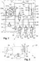
- Fig. 1
- is a block diagram of a twin chamber air dryer for a pneumatic system of a commercial vehicle according to an embodiment of the invention;
- Fig. 2
- depicts a pneumatic system of a commercial vehicle including the device of
figure 1 , according to an embodiment of the invention. - A first embodiment example of the invention is described below by means of
Figs. 1 and 2 . Acommercial vehicle 20 includes apneumatic system 22, which comprises acompressor 2 connected to anengine shaft 25 of a combustion engine of thecommercial vehicle 20, a twin chamber air dryer 1, an ECU (Electronic Control Unit) 10 for controlling the twin chamber air dryer 1, and a pneumatic consumer system 3 connected to the twin chamber air dryer 1; said pneumatic consumer system 3 comprises a multi circuitprotection valve assembly 5,consumers circuits 4 and an alternativesystem pressure storage 14. - The twin chamber air dryer 1 comprises:
- a
supply inlet port 11 connected to thecompressor 2, - an
supply outlet 21 for supplying the multi circuitprotection valve assembly 5 and theconsumer circuits 4 with dried compressed air, - an external fill port 12,
- an
exhaust outlet 30 - a
safety valve outlet 31, - and a
compressor control outlet 40, which feeds a pneumatic signal into anunloader port 2a of thecompressor 2, for switching thecompressor 2 between an on-load mode (active mode) and an off-load mode (inactive mode). Furthermore, the twin chamber air dryer 1 comprises asolenoid valve assembly 6, which is explained below. - In its on-load mode the
compressor 2 is supplying pressurized air; in its off-load mode thecompressor 2 can in particular be switched OFF or be provided an idle mode. - The
ECU 10 outputs electrical control signals S1, S2, S3 to thesolenoid valve assembly 6. Further theECU 10 receives an electrical pressure control signal S4 from apressure sensor 45 for sensing a system pressure p21. Thepressure sensor 45 is provided at thesupply outlet 21 or in the pneumatic consumer system 3 connected to thesupply outlet 21, for example in one of theconsumer circuits 4 connected to the multi circuitprotection valve assembly 5. - The
solenoid valve assembly 6 includes a direction control solenoid valve 7 for receiving an electrical direction control signal S1, aregeneration solenoid valve 8 for receiving an electrical regeneration control signal S2, and a governor solenoid valve 9 for receiving an electrical governor control signal S3. - The twin chamber air dryer 1 comprises a
first dryer line 41 with afirst desiccant cartridge 101 and asecond dryer line 42 with asecond desiccant cartridge 102, wherein thedesiccant cartridges valve assembly second toggling valve supply inlet port 11 to either thefirst desiccant cartridge 101 or thesecond desiccant cartridge 102. In the basic state shown inFig. 1 thefirst toggling valve 121 remains in its open position for connecting thesupply inlet port 11 to thefirst desiccant cartridge 101, which provides dried pressurized air into afirst outlet line 51. Thepneumatic control port 122a of thesecond toggling valve 122 is connected to thefirst outlet line 51, thereby keeping thesecond toggling valve 122 in its blocking position when thefirst outlet line 51 is pressurized. Contrary, when thefirst outlet line 51 is not pressurized, thesecond toggling valve 122 switches into its open basic position, thereby connecting thesupply inlet port 11 to thesecond desiccant cartridge 102 and pressurizing asecond outlet line 52. The first andsecond outlet line non-return valves supply outlet 21. - Pressure control of the
first toggling valve 121 is realized by the direction control solenoid 7 of thesolenoid valve assembly 6 via apneumatic control port 121a. - In its non-activated basic position the direction control solenoid valve 7 separates the
supply outlet 21 from apneumatic control port 121a of thefirst toggling valve 121; therefore thefirst toggling valve 121 remains in its open basic position, thereby keeping thesecond toggling valve 122 in its blocking position, as described above. When theECU 10 outputs the electrical direction control signal S1, i.e. S1=1, the direction control solenoid valve 7 is switched into its activated open position, thereby connecting thesupply outlet 21 to thepneumatic control port 121a and switching thefirst toggling valve 121 into its activated blocking position, in which the firstair dryer line 41 is connected to theexhaust line 53, which is connected to theexhaust outlet 30 via asilencer 125. - In its blocking position, the
second toggling valve 122 connects the secondair dryer line 42 to theexhaust line 53 and theexhaust outlet 30. - Thus the electrical direction control signal S1 enables a toggling or switching between the operation via the
first desiccant cartridge 101 and via thesecond desiccant cartridge 102, which are therefore operated in an alternating manner. - The respective non-active (passive)
desiccant cartridge regeneration solenoid valve 8 is blocking the connection from thesupply outlet 21 to acheck valve assembly regeneration line 48 to the output of thedesiccant cartridges non-active desiccant cartridge regeneration solenoid valve 8 switches into its open position and connects thesupply outlet 21 to theregeneration line 48, and therefore, theregeneration check valve non-pressurized outlet line respective outlet line supply outlet 21, thus starting a first regeneration phase of thefirst desiccant cartridge 101 or a second regeneration phase of thesecond desiccant cartridge 102 depending on the position of the first andsecond toggling valve - This pressurized air provided at the
supply outlet 21 can therefore be delivered by the other outlet line, i.e. by thesecond outlet line 52 for regeneration of thefirst desiccant cartridge 101 and, accordingly, by thefirst outlet line 51 for regeneration of thesecond desiccant cartridge 102. However, the pressurized air can also be taken from the multi circuitprotection valve assembly 5 and theconsumers circuits 4 connected to thesupply outlet 21, which offers a regeneration phase of thedesiccant cartridge second toggling valve - Thus by switching the
regeneration solenoid valve 8 in its ON position, the regeneration of thepassive desiccant cartridge valve - A
purge valve 126 is realized as a pneumatically controlled 2/2 valve, with a blocking basic position and apneumatic control port 126a, which is controlled by the output of the governor solenoid valve 9, which in turn is electrically controlled by the third control signal, i.e. the governor control signal S3. If S3=0 the governor solenoid valve 9 is in its blocking basic position. If S3=1, the governors solenoid valve 9 switches into its open position, thereby connecting thesupply outlet 21 to thepneumatic control port 126a and switching thepurge valve 126 into its open position, thereby connecting thesupply inlet port 11 via theopen purge valve 126 to the exhaust outlet 30 (via the silencer 125). - If the system pressure p21 at the
supply outlet 21 reaches a cut-out pressure p21_max, the ECU outputs the electrical governor control signal S3, i.e. S3=1, thereby switching the governor solenoid valve 9 into its open position. Therefore, a pneumatic unloader signal p40 is delivered to thepressure input 126a of thepurge valve 126 and switches thepurge valve 126 into its open position, in which the compressed air supplied by thecompressor 2 into thesupply inlet port 11 is directly passed to theexhaust outlet 30. Thus the supplied compressed air is directly unloaded to atmosphere. Further, thecompressor control outlet 40 outputs the pneumatic unloader signal p40 to theunloader port 2a of thecompressor 2, thereby switching thecompressor 2 into its off-load mode. - Preferably the
purge valve 126 itself or a purge valve area around thepurge valve 126 can be electrically heated by anelectrical heater device 127, in order to avoid freezing of thepurge valve 126 or the purge valve area. -
- 1
- twin chamber air dryer
- 2
- compressor
- 2a
- unloader port
- 3
- pneumatic consumer system
- 4
- consumer circuits
- 5
- multi circuit protection valve assembly
- 6
- solenoid valve assembly
- 7
- direction control solenoid valve
- 8
- regeneration solenoid valve
- 9
- governor solenoid valve
- 7a, 8a, 9a
- electrical control ports
- 10
- electronic control unit, ECU
- 11
- supply inlet port
- 12
- external supply inlet port
- 14
- system pressure storage
- 20
- commercial vehicle
- 21
- supply outlet
- 22
- pneumatic system
- 25
- engine shaft
- 30
- exhaust outlet
- 31
- safety valve outlet
- 32
- safety valve
- 40
- compressor control outlet
- 41
- first air dryer line
- 42
- second air dryer line
- 45
- pressure sensor
- 46
- second casing
- 47
- first casing
- 48
- regeneration line
- 51, 52
- outlet line
- 53
- exhaust line
- 101
- first desiccant cartridge
- 102
- second desiccant cartridge
- 121
- first toggling valve
- 122
- second toggling valve
- 121a, 122a
- pneumatic control port of the toggling
valve - 125
- silencer
- 126
- purge valve
- 126a
- pneumatic control port of the
purge valve 126 - 127
- heater device
- 131, 132
- system non-return valves
- 141, 142
- regeneration check valves
- S1
- electrical direction control signal
- S2
- electrical regeneration control signal
- S3
- electrical governor control signal
- S4
- electrical pressure control signal
- p11
- inlet pressure at the
supply inlet port 11 - p21
- system pressure at the
supply outlet 21 - p21_max
- cut-out pressure
- p40
- pneumatic unloader signal
Claims (14)
- Twin chamber air dryer (1) for a pneumatic system (22) of a commercial vehicle (20), said twin chamber air dryer (1) comprising:a supply inlet port (11) to be connected to a compressor (2), a supply outlet (21) for supplying dried compressed air to a pneumatic consumer system (3), a compressor control outlet (40) for delivering a pneumatic unloader signal (p40), an exhaust outlet (30),a first desiccant cartridge (101) and a second desiccant cartridge (102), to be operated alternately,a toggling valve assembly (121, 122) for switching between said first desiccant cartridge (101) and said second desiccant cartridge (102), a pneumatically controlled purge valve (126) switchable between a blocking basic position and an activated position for connecting said supply inlet port (11) to said exhaust outlet (30), anda solenoid valve assembly (6),said solenoid valve assembly (6) comprising- a directional control solenoid valve (7) receiving an electrical direction control signal (S1) and controlling said toggling valve assembly (121, 122),- a regeneration solenoid valve (8) receiving an electrical regeneration control signal (S2) and providing pressurized air in regeneration phases of said desiccant cartridges (101, 102), and- a governor solenoid valve (9) receiving an electrical governor control signal (S3), controlling said purge valve (126), and outputting said pneumatic unloader signal (p40),wherein said solenoid valves (7, 8, 9) can be operated independently by said electrical control signals (S1, S21, S3).
- Twin chamber air dryer (1) according to claim 1,
wherein each desiccant cartridge (101, 102) is operable in an on-load phase, a regeneration phase and a passive phase, respectively. - Twin chamber air dryer (1) according to one of the preceding claims, further comprising a safety valve (32) for releasing an inlet pressure (p11) at said supply inlet port (11).
- Twin chamber air dryer (1) according to one of the preceding claims, wherein said toggling valve assembly (121, 121) comprises a pneumatically controlled first toggling valve (121) connected to said first desiccant cartridge (101)and a pneumatically controlled second toggling valve (122) connected to said second desiccant cartridge (102),wherein said first toggling valve (121) is pneumatically controlled by said directional control solenoid valve (7) and said second toggling valve (122) is controlled by a pneumatic signal coming from said first desiccant cartridge (101).
- Twin chamber air dryer (1) according to claim 4, wherein said first toggling valve (121) and said second toggling valve (122) are 3/2 valves, which are biased into their open basic position for an on-load phase and activated into their closed position for a regeneration phase, respectively.
- Twin chamber air dryer (1) according to one of the preceding claims, wherein a system double check valve is provided, comprising two non-return valves (131), (132) which are connected to said common supply outlet (21).
- Twin chamber air dryer (1) according to one of the preceding claims, wherein said pneumatic unloader signal (p40) delivered by said governor solenoid valve (9) is- output at said compressor control outlet (40), for controlling a compressor mode, and- further fed to a pneumatic control port (126a) of said purge valve (126),wherein said purge valve (126) is provided for short-connecting said supply inlet port (11) to said exhaust outlet (30) in dependence of said pneumatic unloader signal (p40).
- Twin chamber air dryer (1) according to one of the preceding claims, wherein a heater device (127) is provided for electrically heating at least said purge valve (126) and/or an area around said purge valve (126), in order to avoid its freezing.
- Twin chamber air dryer (1) according to one of the preceding claims, wherein a silencer (125) is installed on an exhaust line (53) to reduce noise during discharge of compressed air via said purge valve (126).
- Twin chamber air dryer (1) according to one of the preceding claims, wherein said regeneration solenoid valve (8) is provided for controlling a regeneration phase of said first desiccant cartridge (101) and a regeneration phase of said second desiccant cartridge (102), wherein said regeneration solenoid valve (8) is pressurizing a regeneration line (48) in dependence of said electrical regeneration control signal (S2),
said regeneration line (48) being connected to said first and second desiccant cartridges (101, 102) via a first regeneration check valve (141) and a second regeneration check valve (142), respectively. - Twin chamber air dryer (1) according to one of the preceding claims, wherein at least one of said solenoid valves (7, 8, 9) is an electrically controlled 3/2 valve, connected with its electrical control port (7a, 8a, 9a) to said electronic control unit (10),
wherein said electrically controlled 3/2 valve is biased into its blocking basic position, to be switched into its open position by its respective electrical control signal (S1, S2, S3). - Twin chamber air dryer (1) according to one of the preceding claims, comprisinga first casing (47), in particular a die-casted casing, housing said pneumatically controlled valves anda triple block solenoid casing (46), housing said solenoid valve (7, 8, 9), wherein said triple block solenoid casing (46) is connected to said first casing (47), andwherein pneumatic connections between said first casing (47) and said second casing (46) are realized by openings in said casings (46, 47) and sealings between said casings (46, 47).
- Pneumatic system (22) for a commercial vehicle (20), said pneumatic system (22) comprising:a twin chamber air dryer (1) according to one of the preceding claims, an electronic control unit (10) for outputting said electrical control signals (S1, S2, S3) to said solenoid valve assembly (6),a pneumatically controlled compressor (2) supplying said supply inlet port (11) with compressed air and being pneumatically controlled by said unloader signal (p40) coming from said compressor control outlet (40), anda pneumatic consumer system (3) for receiving dried pressurized air from said supply outlet (21) and providing compressed dried air for said regeneration phase, wherein a pressure sensor (45) is provided at said supply outlet (21) or in said pneumatic consumer system (3), said pressure sensor (45) outputting a sensor signal (S4) to said electronic control unit (10).
- Commercial vehicle (20) comprising a pneumatic system according to claim 13.
Priority Applications (3)
| Application Number | Priority Date | Filing Date | Title |
|---|---|---|---|
| EP21181963.6A EP4112399B1 (en) | 2021-06-28 | 2021-06-28 | Twin chamber air dryer and pneumatic system |
| CN202210634380.9A CN115899027A (en) | 2021-06-28 | 2022-06-07 | Dual chamber air dryer and pneumatic system |
| US17/851,299 US20220412382A1 (en) | 2021-06-28 | 2022-06-28 | Twin chamber air dryer and pneumatic system |
Applications Claiming Priority (1)
| Application Number | Priority Date | Filing Date | Title |
|---|---|---|---|
| EP21181963.6A EP4112399B1 (en) | 2021-06-28 | 2021-06-28 | Twin chamber air dryer and pneumatic system |
Publications (2)
| Publication Number | Publication Date |
|---|---|
| EP4112399A1 EP4112399A1 (en) | 2023-01-04 |
| EP4112399B1 true EP4112399B1 (en) | 2024-01-03 |
Family
ID=77021025
Family Applications (1)
| Application Number | Title | Priority Date | Filing Date |
|---|---|---|---|
| EP21181963.6A Active EP4112399B1 (en) | 2021-06-28 | 2021-06-28 | Twin chamber air dryer and pneumatic system |
Country Status (3)
| Country | Link |
|---|---|
| US (1) | US20220412382A1 (en) |
| EP (1) | EP4112399B1 (en) |
| CN (1) | CN115899027A (en) |
Families Citing this family (1)
| Publication number | Priority date | Publication date | Assignee | Title |
|---|---|---|---|---|
| DE102018112521A1 (en) * | 2018-05-24 | 2019-11-28 | Knorr-Bremse Systeme für Nutzfahrzeuge GmbH | Air treatment device with electronic control unit for supplying at least one consumer circuit of a vehicle |
Family Cites Families (3)
| Publication number | Priority date | Publication date | Assignee | Title |
|---|---|---|---|---|
| DE102013207570A1 (en) * | 2013-04-25 | 2014-10-30 | Siemens Aktiengesellschaft | Apparatus and method for drying air and rail vehicle with such a device |
| DE102015012494A1 (en) * | 2015-09-24 | 2017-03-30 | Wabco Europe Bvba | Drying device of a compressed air supply system |
| DE102015118744A1 (en) * | 2015-11-02 | 2017-05-04 | Knorr-Bremse Systeme für Schienenfahrzeuge GmbH | Compressed air processing device and method for operating such |
-
2021
- 2021-06-28 EP EP21181963.6A patent/EP4112399B1/en active Active
-
2022
- 2022-06-07 CN CN202210634380.9A patent/CN115899027A/en active Pending
- 2022-06-28 US US17/851,299 patent/US20220412382A1/en active Pending
Also Published As
| Publication number | Publication date |
|---|---|
| US20220412382A1 (en) | 2022-12-29 |
| CN115899027A (en) | 2023-04-04 |
| EP4112399A1 (en) | 2023-01-04 |
Similar Documents
| Publication | Publication Date | Title |
|---|---|---|
| US8801111B2 (en) | Vehicle air braking system | |
| US5209764A (en) | Compressed air system with twin air dryers | |
| US6858066B2 (en) | Air dryer module | |
| US8628602B2 (en) | Air processing device with two air dryer cartridges | |
| CA2677459C (en) | Compressed air supply system and method for operating a compressed air supply system | |
| US8740316B2 (en) | Compressed air preparation device | |
| JP5340389B2 (en) | Method for operating a parking brake module in the event of a failure and parking brake module suitable for carrying out the method | |
| JP5101290B2 (en) | Compressed air supply device and method for operation of the compressed air supply device | |
| JP5187664B2 (en) | Compressed air supply system for vehicle and air dryer | |
| EP4112399B1 (en) | Twin chamber air dryer and pneumatic system | |
| JP6403678B2 (en) | Compressed air supply device and method of operating compressed air supply device | |
| US20100071779A1 (en) | Compressed Air Supply System for a Commercial Vehicle, and Method for Operating a Compressed Air Supply System | |
| US20200361436A1 (en) | Braking system for a commerical vehicle, compressed air processing unit and use of a compressed air processing unit | |
| US8616231B2 (en) | Valve device for a compressed air supply device and compressed air supply system | |
| EP3556622B1 (en) | Air supply unit for a pneumatic system of a commercial vehicle | |
| EP3113994B1 (en) | Dual purpose dryers for high flow | |
| JP2002523286A (en) | Air dryer | |
| JP2021506660A (en) | Equipment for commercial vehicles | |
| EP3995373A1 (en) | Air dryer with direct solenoid control |
Legal Events
| Date | Code | Title | Description |
|---|---|---|---|
| PUAI | Public reference made under article 153(3) epc to a published international application that has entered the european phase |
Free format text: ORIGINAL CODE: 0009012 |
|
| STAA | Information on the status of an ep patent application or granted ep patent |
Free format text: STATUS: THE APPLICATION HAS BEEN PUBLISHED |
|
| AK | Designated contracting states |
Kind code of ref document: A1 Designated state(s): AL AT BE BG CH CY CZ DE DK EE ES FI FR GB GR HR HU IE IS IT LI LT LU LV MC MK MT NL NO PL PT RO RS SE SI SK SM TR |
|
| STAA | Information on the status of an ep patent application or granted ep patent |
Free format text: STATUS: REQUEST FOR EXAMINATION WAS MADE |
|
| 17P | Request for examination filed |
Effective date: 20230704 |
|
| RBV | Designated contracting states (corrected) |
Designated state(s): AL AT BE BG CH CY CZ DE DK EE ES FI FR GB GR HR HU IE IS IT LI LT LU LV MC MK MT NL NO PL PT RO RS SE SI SK SM TR |
|
| GRAP | Despatch of communication of intention to grant a patent |
Free format text: ORIGINAL CODE: EPIDOSNIGR1 |
|
| STAA | Information on the status of an ep patent application or granted ep patent |
Free format text: STATUS: GRANT OF PATENT IS INTENDED |
|
| RIC1 | Information provided on ipc code assigned before grant |
Ipc: B01D 53/26 20060101ALI20230814BHEP Ipc: B01D 53/04 20060101ALI20230814BHEP Ipc: B60T 17/00 20060101AFI20230814BHEP |
|
| INTG | Intention to grant announced |
Effective date: 20230919 |
|
| GRAS | Grant fee paid |
Free format text: ORIGINAL CODE: EPIDOSNIGR3 |
|
| GRAA | (expected) grant |
Free format text: ORIGINAL CODE: 0009210 |
|
| STAA | Information on the status of an ep patent application or granted ep patent |
Free format text: STATUS: THE PATENT HAS BEEN GRANTED |
|
| AK | Designated contracting states |
Kind code of ref document: B1 Designated state(s): AL AT BE BG CH CY CZ DE DK EE ES FI FR GB GR HR HU IE IS IT LI LT LU LV MC MK MT NL NO PL PT RO RS SE SI SK SM TR |
|
| REG | Reference to a national code |
Ref country code: GB Ref legal event code: FG4D |
|
| REG | Reference to a national code |
Ref country code: CH Ref legal event code: EP |
|
| REG | Reference to a national code |
Ref country code: DE Ref legal event code: R096 Ref document number: 602021008236 Country of ref document: DE |
|
| REG | Reference to a national code |
Ref country code: IE Ref legal event code: FG4D |
|
| REG | Reference to a national code |
Ref country code: LT Ref legal event code: MG9D |