EP4112393A1 - Side airbag device and airbag module manufacturing method - Google Patents
Side airbag device and airbag module manufacturing method Download PDFInfo
- Publication number
- EP4112393A1 EP4112393A1 EP21761702.6A EP21761702A EP4112393A1 EP 4112393 A1 EP4112393 A1 EP 4112393A1 EP 21761702 A EP21761702 A EP 21761702A EP 4112393 A1 EP4112393 A1 EP 4112393A1
- Authority
- EP
- European Patent Office
- Prior art keywords
- cushion
- inflator
- vehicle
- frame
- end part
- Prior art date
- Legal status (The legal status is an assumption and is not a legal conclusion. Google has not performed a legal analysis and makes no representation as to the accuracy of the status listed.)
- Granted
Links
Images



Classifications
-
- B—PERFORMING OPERATIONS; TRANSPORTING
- B60—VEHICLES IN GENERAL
- B60R—VEHICLES, VEHICLE FITTINGS, OR VEHICLE PARTS, NOT OTHERWISE PROVIDED FOR
- B60R21/00—Arrangements or fittings on vehicles for protecting or preventing injuries to occupants or pedestrians in case of accidents or other traffic risks
- B60R21/02—Occupant safety arrangements or fittings, e.g. crash pads
- B60R21/16—Inflatable occupant restraints or confinements designed to inflate upon impact or impending impact, e.g. air bags
- B60R21/20—Arrangements for storing inflatable members in their non-use or deflated condition; Arrangement or mounting of air bag modules or components
- B60R21/207—Arrangements for storing inflatable members in their non-use or deflated condition; Arrangement or mounting of air bag modules or components in vehicle seats
-
- B—PERFORMING OPERATIONS; TRANSPORTING
- B60—VEHICLES IN GENERAL
- B60R—VEHICLES, VEHICLE FITTINGS, OR VEHICLE PARTS, NOT OTHERWISE PROVIDED FOR
- B60R21/00—Arrangements or fittings on vehicles for protecting or preventing injuries to occupants or pedestrians in case of accidents or other traffic risks
- B60R21/02—Occupant safety arrangements or fittings, e.g. crash pads
- B60R21/16—Inflatable occupant restraints or confinements designed to inflate upon impact or impending impact, e.g. air bags
- B60R21/20—Arrangements for storing inflatable members in their non-use or deflated condition; Arrangement or mounting of air bag modules or components
- B60R21/201—Packaging straps or envelopes for inflatable members
-
- B—PERFORMING OPERATIONS; TRANSPORTING
- B60—VEHICLES IN GENERAL
- B60R—VEHICLES, VEHICLE FITTINGS, OR VEHICLE PARTS, NOT OTHERWISE PROVIDED FOR
- B60R21/00—Arrangements or fittings on vehicles for protecting or preventing injuries to occupants or pedestrians in case of accidents or other traffic risks
- B60R21/02—Occupant safety arrangements or fittings, e.g. crash pads
- B60R21/16—Inflatable occupant restraints or confinements designed to inflate upon impact or impending impact, e.g. air bags
- B60R21/23—Inflatable members
- B60R21/231—Inflatable members characterised by their shape, construction or spatial configuration
- B60R21/23138—Inflatable members characterised by their shape, construction or spatial configuration specially adapted for side protection
-
- B—PERFORMING OPERATIONS; TRANSPORTING
- B60—VEHICLES IN GENERAL
- B60R—VEHICLES, VEHICLE FITTINGS, OR VEHICLE PARTS, NOT OTHERWISE PROVIDED FOR
- B60R21/00—Arrangements or fittings on vehicles for protecting or preventing injuries to occupants or pedestrians in case of accidents or other traffic risks
- B60R21/02—Occupant safety arrangements or fittings, e.g. crash pads
- B60R21/16—Inflatable occupant restraints or confinements designed to inflate upon impact or impending impact, e.g. air bags
- B60R21/23—Inflatable members
- B60R21/237—Inflatable members characterised by the way they are folded
-
- B—PERFORMING OPERATIONS; TRANSPORTING
- B60—VEHICLES IN GENERAL
- B60R—VEHICLES, VEHICLE FITTINGS, OR VEHICLE PARTS, NOT OTHERWISE PROVIDED FOR
- B60R21/00—Arrangements or fittings on vehicles for protecting or preventing injuries to occupants or pedestrians in case of accidents or other traffic risks
- B60R21/02—Occupant safety arrangements or fittings, e.g. crash pads
- B60R21/16—Inflatable occupant restraints or confinements designed to inflate upon impact or impending impact, e.g. air bags
- B60R21/23—Inflatable members
- B60R21/231—Inflatable members characterised by their shape, construction or spatial configuration
- B60R21/23138—Inflatable members characterised by their shape, construction or spatial configuration specially adapted for side protection
- B60R2021/23146—Inflatable members characterised by their shape, construction or spatial configuration specially adapted for side protection seat mounted
Definitions
- the present invention relates to a side airbag device and a manufacturing method of an airbag module constituting a side airbag device installed in a vehicle seat in a vehicle cabin in order to protect an occupant, for example, when a vehicle is impacted from a side (hereinafter referred to as a side impact).
- the present invention relates to a side airbag device containing an airbag module having a soft cover wound around an outer periphery thereof, and a manufacturing method of the airbag module.
- up and “upper” refer to the head direction of an occupant seated in a normal position in the seat
- down and “lower” refer to the foot direction of the same occupant
- front and “forward” refer to the frontward direction of an occupant seated in a normal position in the seat
- rear and “rearward” refer to the back direction of the same occupant
- width direction means the directions toward the left hand and right hand of an occupant seated in a normal position in the seat.
- a "normal position” in the description above refers to a position along which the entire back of the occupant is in contact with the backrest of the seat at a center position in the width direction of the seat cushion that constitutes the seat.
- "occupant” in the above description assumes an AM50 (a 50th percentile of an adult male in US) of World SID (Word Side Impact Dummy).
- a side airbag device that suppresses movement of the occupant toward the part where the impact is applied is configured such that a signal transmitted by a sensor that detects the impact activates an inflator so as to generate gas in order to expand and deploy a cushion to the side of the occupant seated in a vehicle seat.
- the side airbag device is, as illustrated in FIG. 5 , for example, a cushion 2 with an inflator 3 stowed therein that is stowed inside a side part of the backrest portion (hereinafter seatback SB) of a seat S in a state of being folded in a bellows shape in front-to-back direction of the vehicle.
- seatback SB backrest portion
- 1 represents the airbag module having the inflator 3 stowed in the cushion 2
- 3a represents a stud bolt, for example two thereof, provided in a protruding state in the longitudinal direction on the outer periphery of the inflator 3
- 4 represents a nut to attach to the stud bolt 3a.
- SF indicates a side frame built in both left and right sides of the seat back SB
- SD indicates a side door.
- a soft cover 5 is wound around an outer peripheral portion of the airbag module 1.
- a hole 5c provided in a first end 5a of the soft cover 5 is mated and engaged with the stud bolt 3a of the inflator 3. Thereafter, a second end 5b is wound from the side the inflator 3 is stowed in so as to surround the folded side of the cushion 2, and mating a hole 5d provided on the second end 5b to the stud bolt 3a of the inflator 3 enables the soft cover 5 to be wound around the airbag module 1.
- Patent Document 1 a technique for resolving the disadvantages has been proposed in Patent Document 1.
- the technology proposed in Patent Document 1 includes, as illustrated in FIG. 7 , a protective flap 6 arranged on the side frame SF side of the airbag module 1 that includes the folded part 2f on the seat side of the cushion 2 in proximity to the inflator 3.
- the protective flap 6 is provided with a hole 6a for inserting the stud bolt 3a of the inflator 3 and is sewn to the soft cover 5 and the cushion 2 so there is no deviation in placement position.
- Patent Document 1 U.S. Patent Application Publication No. 2015/0123382 Specification
- the protective flap can effectively prevent the cushion from getting caught, but there is a disadvantage that the protective wrap is additionally required, and this increases the number of steps for manufacturing of the airbag module. In addition, there is concern that the cushion getting caught may occur due to manufacturing variations.
- a problem to be solved by the present invention is that the cushion may get caught between the side frame and the inflator stowing portion when assembling the airbag module with the soft cover wound around the outer periphery to a vehicle.
- the cushion getting caught can be effectively prevented, but the protective wrap is additionally required, and the number of assembly steps of the airbag module increases. In addition, the cushion getting caught may occur due to manufacturing variations.
- An object of the present invention is to effectively prevent the cushion from getting caught without requiring an extra component besides the soft cover when assembling the airbag module to a vehicle.
- the present invention is a side airbag device for suppressing movement of an occupant in a vehicle collision and protecting the occupant provided with an airbag module having an inflator stowed in a cushion attached to a frame of a seat.
- a soft cover is wound around the outer periphery of the airbag module.
- the soft cover includes:
- the folded portion of the cushion on the frame side close to the inflator is pulled away from the attachment portion of the inflator to the frame by the tensile force acting on the soft cover. Therefore, effectively preventing the folded portion of the cushion from being caught between the frame and the inflator stowed in the cushion.
- the first side part of the soft cover should have a sewn portion sewn to the cushion near the stowing portion of the inflator of the cushion or have an insertion hole for the stud bolt of the inflator. Because in the case of such a configuration, when attaching the airbag module to the frame, the folded portion of the cushion on the frame side close to the inflator is pulled away from the attachment portion of the inflator to the frame by the first side part of the soft cover.
- having a space between the folded portion on the first side part of the soft cover which is the frame side close to the inflator, and the stowing portion of the inflator is desirable. This is because, when attaching the airbag module to the frame, even a portion of the folded cushion is likely to be caught between the frame and inflator stowing portion of the cushion, a portion thereof moves due to the presence of the space, and may avoid getting caught.
- the folded portion of the cushion on the frame side in proximity to the inflator is pulled away from the portion where the inflator attaches to the frame. Therefore, the folded portion can be effectively prevented from being caught between the frame and the inflator stowing portion of the cushion.
- An object of the present invention is to prevent a cushion from getting caught without requiring an extra component in addition to a soft cover when assembling an airbag module to a vehicle.
- the object of the present invention is achieved by winding the soft cover that is wrapped around the airbag module from a frame and an inflator stowing portion of the cushion along a side surface of the cushion frame to an end part toward the front of the vehicle, then along the side surface of the cushion on the side opposite the frame to an end part toward the rear of the vehicle.
- a side airbag device 10 is attached to side frame SF arranged on both the left and right sides of the seat back SB, for example, which functions as a framework of the seat S.
- the side airbag device 10 is attached to the side door SD side of the side frame SF.
- "seat side" in the following description means the same direction as "frame side”.
- the side airbag device 10 includes, for example, an airbag module 1 where a cushion 2 in which an inflator 3 is stowed is folded in the front-to-back direction of the vehicle and the folded state is maintained by winding a soft cover 11 around the outer periphery thereof.
- the cushion 2 is formed longer in the up-down direction than the front-to-back direction in order to cover an upper body of an occupant from the side, and for example, formed in a bag shape by sewing outer periphery portions of 2 pierces of base material panels together to increase thickness in the left-right direction.
- the inflator 3 is configured to receive a signal from a sensor and discharge gas into the interior of the cushion 2 from a gas discharge hole provided on the outer surface thereof.
- the airbag module 1 is attached to the side frame SF on the side door SD side, for example, using two stud bolts 3a provided at appropriate intervals in a protruding manner in the longitudinal direction of the exterior surface of the inflator 3 opposite the gas discharge hole.
- the form of the soft cover 11 and the manufacturing method of the airbag module differ significantly from that of the side airbag device having the airbag module 1 with a conventional soft cover wound thereon.
- the soft cover 11 used in the present invention is attached to the side frame SF and has a length in the vertical direction corresponding in general to the length of the cushion 2 in a folded state in the vertical direction of the vehicle.
- the first side part 11a, the front end part 11b, the second side part 11c, the rear end part 11d, and the engaging part 11e are continuously provided from the rear to the front of the vehicle.
- the first side part 11a extends from the side frame SF and the inflator 3 stowing portion of the cushion 2 along a side surface 2a of the folded cushion 2 on the frame side (seat side) toward the front of the vehicle and is a portion that covers the side surface 2a.
- the insertion hole 11f of the stud bolt 3a of the inflator 3 is provided on the first side part 11a.
- the front end part 11b is a part that extends continuously from the front end of the first side part 11a and covers an end part toward the front of the vehicle 2b of the folded cushion 2 of the airbag module 1 in a state attached to the side frame SF.
- the second side part 11c is a part that extends continuously from the front end part 11b toward the rear of the vehicle along a side surface 2c on a side of the folded cushion 2 of the airbag module 1 on the side opposite that of the frame (side opposite the seat S) and covers the side surface 2c.
- the rear end part 11d is a part that extends continuously from the second side part 11c and covers the end part toward rear end of vehicle 2d of the folded cushion 2 of the airbag module 1 in the attached state.
- the engaging part 11e is a part that extends continuously from the rear end part 11d, overlaps with a portion of the first side part 11a and the outside thereof, and is engaged to the stud bolt 3a of the inflator 2.
- an insertion hole 11g for the stud bolt 3a of the inflator 3 is provided in the engagement part.
- the front end part 11b refers to the entire region between the first side part 11a and the second side part 11c, and is positioned on the front surface of the airbag module 1 in a state where the soft cover 11 is wound around the outer periphery of the airbag device 10.
- the rear end part 11d refers to the entire region between the second side part 11c and the engaging part 11e, and is positioned on the rear surface of the airbag module 1 in a state where the soft cover 11 is wound around the outer periphery of the airbag device 10.
- the airbag module 1 including the soft cover 11 having the above configuration is assembled and manufactured in the following order.
- “seat side” in the following description means the same direction as "frame side”.
- the protruding hole 2e of the stud bolt 3a provided in the stowing portion where the inflator 3 of the cushion 2 is stowed and the insertion hole 11f provided on the first side part 11a of the soft cover 11 are aligned.
- the soft cover 11 is sewn to the cushion 2 on the front end part 11b side of the insertion hole 11f and side opposite the front end part 11b.
- the reference 12 in FIG. 2 indicates the sewn part of the soft cover 11 and cushion 2.
- providing at least one sewn part 12 on the each of the insertion holes 11f for the stud bolts 3a in the vehicle front-to-back direction increases the strength of the stitches of the soft cover 11 and cushion 2.
- the cushion 2 main body portion is folded into a bellows shape in the front-back direction of the vehicle, and the leading end is folded into a roll shape.
- the first side part 11a, the front end part 11b, the second side part 11c, and the rear end part 11d of the soft cover 11 are wound so as to cover each of the frame side (seat side) surface 2a, the end part toward front end of vehicle 2b, the side surface 2c on the side opposite the frame (side opposite the seat S), and the end part toward rear end of vehicle 2d of the cushion 2.
- the stud bolt 3a of the inflator 3 is inserted into the insertion hole 11g provided on the engaging part 11e, and engaged.
- a space 13 is formed between the frame side close to the inflator 3 of the cushion 2 main body portion, in other words, the folded part 2f of first side part 11a of the soft cover 11, and the stowing portion of the inflator 3.
- the folded part 2f on the frame side of the cushion 2 close to the inflator 3 is pulled in a direction (arrow B) away from the portion of the side frame SF that the inflator 3 is attached to.
- a portion of the folded part 2f of the cushion 2 can effectively be prevented from being caught between the side frame SF and the inflator 3 stowed in the cushion 2. Even if the folded part 2f getting caught between the side frame SF and the inflator 3 stowing portion of the cushion 2 is likely, a portion thereof moves due to the presence of the space 13, and getting caught is less likely to occur.
- the side airbag device and the airbag module manufacturing method described above are preferred examples of the present invention, and Embodiments other than these examples are included.
- the shape, size, configuration, arrangement, and the like of the detailed parts illustrated in the accompanying drawings do not restrict the present invention.
- expressions and terms used in the specification of the present application are for the purpose of description and are not limiting unless otherwise specified.
- the side airbag device 10 is attached to the side door SD side of the side frame SF, but as illustrated in FIG. 3 , the side airbag device 10 may be attached to the side frame SF on the center side in the vehicle width direction.
- winding the soft cover 11 in the direction of the arrow B in FIG. 3 (opposite direction of the Embodiment described above) enables implementation of the present invention and obtaining the same effect as the effect described above.
- the side airbag device 10 (airbag module 1) of the present invention is provided on a side closer to the side door SD (near side) of the seat S, but may be provided on the center side in the vehicle width direction (far side).
- the insertion hole 11f of the stud bolt 3a is provided on the first side part 11a of the soft cover 11, but if the stud bolt 3a can penetrate through the first side part 11a, a cutout 11h as illustrated in FIG. 4 may be provided.
- the positioning of the soft cover 11 on the cushion 2 is set by the insertion hole 11f for the stud bolt 3a provided on the first side part 11a of the soft cover 11 and the sewn part 12.
- the positioning can also be set by adhering the soft cover 11 and the cushion 2.
- the length of the soft cover 11 in the up-down direction corresponds generally to the length of the cushion 2 attached to the side frame SF in the folded state in the up-down direction of the vehicle.
- the length of the soft cover 11 in the up-down direction may be shorter than the length in the up-down direction of the vehicle of the cushion 2 in the folded state.
- the cushion 2 is folded in a bellows shape and a roll shape in the front-rear direction of the vehicle, but may be folded in a bellows shape in the front-rear direction of the vehicle as illustrated in FIG. 5 .
- folding in a bellows shape in the width direction of the vehicle is also feasible.
- folding in a roll shape is also feasible.
- the present invention can also be applied to a self-driving vehicle having a high degree of freedom with respect to the orientation of the seat, such that the orientation of the seat is not fixed in the vehicle travel direction, and can be rotated 180° degrees until facing in the reverse direction of the vehicle travel direction.
- the cushion 2 of the present invention is not limited to being joined by a suitable number of sewn base material panels, and can also be formed by using a technology called one-piece weaving.
Landscapes
- Engineering & Computer Science (AREA)
- Mechanical Engineering (AREA)
- Air Bags (AREA)
Abstract
a first side part 11a that extends from between a side frame SF where the airbag module 1 is attached to the side frame SF and the inflator 3 stowed in the cushion 2 along the side surface of the folded cushion 2 on the frame side toward the front,
a front end part 11b wound around the end part of the cushion 2 towards the front of the vehicle,
a second side part 11c extending along the side surface of the cushion 2 on the side opposite the frame toward the rear of the vehicle,
a rear end part 11d wound around the end part of the cushion 2 toward the rear of the vehicle, and
an engaging part 11e that overlaps with a portion of the first side part 11a and engages with the stud bolt 3a of the inflator 3.
Description
- The present invention relates to a side airbag device and a manufacturing method of an airbag module constituting a side airbag device installed in a vehicle seat in a vehicle cabin in order to protect an occupant, for example, when a vehicle is impacted from a side (hereinafter referred to as a side impact). In particular, the present invention relates to a side airbag device containing an airbag module having a soft cover wound around an outer periphery thereof, and a manufacturing method of the airbag module.
- As used in this application, "up" and "upper" refer to the head direction of an occupant seated in a normal position in the seat, and "down" and "lower" refer to the foot direction of the same occupant. In addition, "front" and "forward" refer to the frontward direction of an occupant seated in a normal position in the seat, and "rear" and "rearward" refer to the back direction of the same occupant. Moreover, the "width direction" means the directions toward the left hand and right hand of an occupant seated in a normal position in the seat. Note that a "normal position" in the description above refers to a position along which the entire back of the occupant is in contact with the backrest of the seat at a center position in the width direction of the seat cushion that constitutes the seat. Furthermore, "occupant" in the above description assumes an AM50 (a 50th percentile of an adult male in US) of World SID (Word Side Impact Dummy).
- For example, upon a side impact, a side airbag device that suppresses movement of the occupant toward the part where the impact is applied is configured such that a signal transmitted by a sensor that detects the impact activates an inflator so as to generate gas in order to expand and deploy a cushion to the side of the occupant seated in a vehicle seat.
- The side airbag device is, as illustrated in
FIG. 5 , for example, acushion 2 with aninflator 3 stowed therein that is stowed inside a side part of the backrest portion (hereinafter seatback SB) of a seat S in a state of being folded in a bellows shape in front-to-back direction of the vehicle. Note that, inFIG. 5 ,1 represents the airbag module having theinflator 3 stowed in thecushion inflator stud bolt 3a. In addition, SF indicates a side frame built in both left and right sides of the seat back SB, and SD indicates a side door. - In order to maintain the folded state of the cushion while the side airbag device is being assembled, being transported to a vehicle manufacturer, being assembled to a vehicle, and during standard usage of a vehicle, as illustrated in
FIG. 6 , asoft cover 5 is wound around an outer peripheral portion of theairbag module 1. - A hole 5c provided in a first end 5a of the
soft cover 5 is mated and engaged with thestud bolt 3a of theinflator 3. Thereafter, asecond end 5b is wound from the side theinflator 3 is stowed in so as to surround the folded side of thecushion 2, and mating ahole 5d provided on thesecond end 5b to thestud bolt 3a of theinflator 3 enables thesoft cover 5 to be wound around theairbag module 1. - However, in the case of the winding of the
soft cover 5, when theairbag module 1 is assembled to a vehicle, a foldedpart 2f on the seat side in proximity to theinflator 3 is caught between a side frame SF and the inflator stowing portion of thecushion 2 due to the tensile force (arrow A). In this case, damage occurs to the portion of thecushion 2 that is caught. - Therefore, a technique for resolving the disadvantages has been proposed in
Patent Document 1. The technology proposed inPatent Document 1 includes, as illustrated inFIG. 7 , aprotective flap 6 arranged on the side frame SF side of theairbag module 1 that includes the foldedpart 2f on the seat side of thecushion 2 in proximity to theinflator 3. Note that theprotective flap 6 is provided with ahole 6a for inserting thestud bolt 3a of theinflator 3 and is sewn to thesoft cover 5 and thecushion 2 so there is no deviation in placement position. -
Patent Document 1U.S. Patent Application Publication No. 2015/0123382 Specification - However, in the case of the technology proposed in
Patent Document 1, the protective flap can effectively prevent the cushion from getting caught, but there is a disadvantage that the protective wrap is additionally required, and this increases the number of steps for manufacturing of the airbag module. In addition, there is concern that the cushion getting caught may occur due to manufacturing variations. - A problem to be solved by the present invention is that the cushion may get caught between the side frame and the inflator stowing portion when assembling the airbag module with the soft cover wound around the outer periphery to a vehicle.
- On the other hand, in the case of the side airbag device proposed in
Patent Document 1, the cushion getting caught can be effectively prevented, but the protective wrap is additionally required, and the number of assembly steps of the airbag module increases. In addition, the cushion getting caught may occur due to manufacturing variations. - An object of the present invention is to effectively prevent the cushion from getting caught without requiring an extra component besides the soft cover when assembling the airbag module to a vehicle.
- The present invention is a side airbag device for suppressing movement of an occupant in a vehicle collision and protecting the occupant provided with an airbag module having an inflator stowed in a cushion attached to a frame of a seat.
- In the side airbag device of the present invention, a soft cover is wound around the outer periphery of the airbag module.
- Furthermore, with the present invention, an important feature is that the soft cover includes:
- a first side part extending from the stowing portion of the inflator in the cushion along the side surface of the folded cushion on the frame side toward the front of the vehicle,
- a front end part extending continuously from a front end of the first side part and wound around the end part of the cushion towards the front of the vehicle, a second side part extending continuously from the front end part along a side surface of the cushion on the side opposite the frame and extending toward the rear of the vehicle,
- a rear end part extending continuously from the second side part and wound around a rear end part of the cushion towards the rear of the vehicle, and an engaging part extending continuously from the rear end part and overlapping with a portion of the first side part and engaged to a stud bolt of the inflator.
- With the airbag module constituting the side airbag device according to the present invention,
- a protrusion hole in the inflator stowing portion of the cushion for the stud bolt is aligned with the insertion part of the stud bolt provided on the first side portion of the soft cover,
- the soft cover is attached to the cushion,
- the inflator is stowed in the cushion,
- the cushion is folded,
- the soft cover is wound, with a first side thereof covering the side surface of the cushion on the frame side, a front end part thereof covering around the end part of the cushion toward the front of the vehicle, a second side part thereof covering the side surface of the cushion on the side opposite the frame, and a rear end part thereof covering the end part of the cushion toward the rear of the vehicle, and
- the engaging part engages with the inflator stud bolt and overlaps a portion of the first side part.
- This is a manufacturing method of the airbag module of the present invention.
- In the present invention, when attaching the airbag module to the frame of the seat, the folded portion of the cushion on the frame side close to the inflator is pulled away from the attachment portion of the inflator to the frame by the tensile force acting on the soft cover. Therefore, effectively preventing the folded portion of the cushion from being caught between the frame and the inflator stowed in the cushion.
- In the present invention, the first side part of the soft cover should have a sewn portion sewn to the cushion near the stowing portion of the inflator of the cushion or have an insertion hole for the stud bolt of the inflator. Because in the case of such a configuration, when attaching the airbag module to the frame, the folded portion of the cushion on the frame side close to the inflator is pulled away from the attachment portion of the inflator to the frame by the first side part of the soft cover.
- In addition, in the present invention, having a space between the folded portion on the first side part of the soft cover which is the frame side close to the inflator, and the stowing portion of the inflator is desirable. This is because, when attaching the airbag module to the frame, even a portion of the folded cushion is likely to be caught between the frame and inflator stowing portion of the cushion, a portion thereof moves due to the presence of the space, and may avoid getting caught.
- With the present invention, when attaching the airbag module to the seat frame, the folded portion of the cushion on the frame side in proximity to the inflator is pulled away from the portion where the inflator attaches to the frame. Therefore, the folded portion can be effectively prevented from being caught between the frame and the inflator stowing portion of the cushion.
-
-
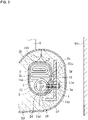
FIG. 1 is a cross-sectional view illustrating a state of an airbag module constituting a side airbag device of the present invention attached to a side frame; -
FIG. 2 is an expanded view of a soft cover constituting the airbag module of the side airbag device of the present invention; -
FIG. 3 is a cross-sectional view illustrating a state of another example of an airbag module constituting a side airbag device of the present invention attached to a side frame; -
FIG. 4 is an expanded view of another example of the soft cover constituting the airbag module of the side airbag device of the present invention; -
FIG. 5 is a partial cross-sectional view of an airbag module constituting a conventional side airbag device attached to a side frame, viewed from a horizontal direction; -
FIG. 6 is a cross-sectional view illustrating the airbag module constituting the conventional side airbag device attached to a side frame; and -
FIG. 7 is a cross-sectional view illustrating an airbag module constituting a side airbag device proposed inPatent Document 1 attached to a side frame. - An object of the present invention is to prevent a cushion from getting caught without requiring an extra component in addition to a soft cover when assembling an airbag module to a vehicle.
- The object of the present invention is achieved by winding the soft cover that is wrapped around the airbag module from a frame and an inflator stowing portion of the cushion along a side surface of the cushion frame to an end part toward the front of the vehicle, then along the side surface of the cushion on the side opposite the frame to an end part toward the rear of the vehicle.
- An embodiment of the present invention is described below using the attached diagrams. Note that the explanations of the embodiments below are examples of the present invention, and are not intended to limit the scope of the present invention, the application, and the uses thereof.
- As described in
FIG. 5 , aside airbag device 10 is attached to side frame SF arranged on both the left and right sides of the seat back SB, for example, which functions as a framework of the seat S. In addition, in the Embodiment illustrated inFIG. 1 , theside airbag device 10 is attached to the side door SD side of the side frame SF. In the present Embodiment, "seat side" in the following description means the same direction as "frame side". - The
side airbag device 10 includes, for example, anairbag module 1 where acushion 2 in which aninflator 3 is stowed is folded in the front-to-back direction of the vehicle and the folded state is maintained by winding asoft cover 11 around the outer periphery thereof. - The
cushion 2 is formed longer in the up-down direction than the front-to-back direction in order to cover an upper body of an occupant from the side, and for example, formed in a bag shape by sewing outer periphery portions of 2 pierces of base material panels together to increase thickness in the left-right direction. - Additionally, the
inflator 3 is configured to receive a signal from a sensor and discharge gas into the interior of thecushion 2 from a gas discharge hole provided on the outer surface thereof. - Furthermore, the
airbag module 1 is attached to the side frame SF on the side door SD side, for example, using twostud bolts 3a provided at appropriate intervals in a protruding manner in the longitudinal direction of the exterior surface of theinflator 3 opposite the gas discharge hole. - Regarding the
side airbag device 10 of the present invention, the form of thesoft cover 11 and the manufacturing method of the airbag module differ significantly from that of the side airbag device having theairbag module 1 with a conventional soft cover wound thereon. - In other words, except for an
engaging part 11e described below, thesoft cover 11 used in the present invention is attached to the side frame SF and has a length in the vertical direction corresponding in general to the length of thecushion 2 in a folded state in the vertical direction of the vehicle. On the other hand, in the front-rear direction of the vehicle in the state where theairbag module 1 is attached to the side frame SF, as illustrated inFIG. 2 , thefirst side part 11a, thefront end part 11b, thesecond side part 11c, therear end part 11d, and theengaging part 11e are continuously provided from the rear to the front of the vehicle. - The
first side part 11a extends from the side frame SF and theinflator 3 stowing portion of thecushion 2 along aside surface 2a of the foldedcushion 2 on the frame side (seat side) toward the front of the vehicle and is a portion that covers theside surface 2a. In the Embodiment illustrated inFIG. 2 , theinsertion hole 11f of thestud bolt 3a of theinflator 3 is provided on thefirst side part 11a. - In addition, the
front end part 11b is a part that extends continuously from the front end of thefirst side part 11a and covers an end part toward the front of thevehicle 2b of the foldedcushion 2 of theairbag module 1 in a state attached to the side frame SF. - In addition, the
second side part 11c is a part that extends continuously from thefront end part 11b toward the rear of the vehicle along aside surface 2c on a side of the foldedcushion 2 of theairbag module 1 on the side opposite that of the frame (side opposite the seat S) and covers theside surface 2c. - In addition, the
rear end part 11d is a part that extends continuously from thesecond side part 11c and covers the end part toward rear end ofvehicle 2d of the foldedcushion 2 of theairbag module 1 in the attached state. - In addition, the
engaging part 11e is a part that extends continuously from therear end part 11d, overlaps with a portion of thefirst side part 11a and the outside thereof, and is engaged to thestud bolt 3a of theinflator 2. In the Embodiment illustrated inFIG. 2 , aninsertion hole 11g for thestud bolt 3a of theinflator 3 is provided in the engagement part. - Note that, as understood from
FIG. 2 illustrating the expanded view, thefront end part 11b refers to the entire region between thefirst side part 11a and thesecond side part 11c, and is positioned on the front surface of theairbag module 1 in a state where thesoft cover 11 is wound around the outer periphery of theairbag device 10. Similarly, therear end part 11d refers to the entire region between thesecond side part 11c and theengaging part 11e, and is positioned on the rear surface of theairbag module 1 in a state where thesoft cover 11 is wound around the outer periphery of theairbag device 10. - The
airbag module 1 including thesoft cover 11 having the above configuration is assembled and manufactured in the following order. Note that in the present embodiment, "seat side" in the following description means the same direction as "frame side". - First, the protruding
hole 2e of thestud bolt 3a provided in the stowing portion where theinflator 3 of thecushion 2 is stowed and theinsertion hole 11f provided on thefirst side part 11a of thesoft cover 11 are aligned. Then, in the aligned state, thesoft cover 11 is sewn to thecushion 2 on thefront end part 11b side of theinsertion hole 11f and side opposite thefront end part 11b. Thereference 12 inFIG. 2 indicates the sewn part of thesoft cover 11 andcushion 2. In the present Embodiment, providing at least onesewn part 12 on the each of theinsertion holes 11f for thestud bolts 3a in the vehicle front-to-back direction increases the strength of the stitches of thesoft cover 11 andcushion 2. - After the
inflator 3 is stowed in thecushion 2 with thesoft cover 11 sewn to the aforementioned stowing portion, as illustrated inFIG. 1 , for example, thecushion 2 main body portion is folded into a bellows shape in the front-back direction of the vehicle, and the leading end is folded into a roll shape. - Next, the
first side part 11a, thefront end part 11b, thesecond side part 11c, and therear end part 11d of thesoft cover 11 are wound so as to cover each of the frame side (seat side)surface 2a, the end part toward front end ofvehicle 2b, theside surface 2c on the side opposite the frame (side opposite the seat S), and the end part toward rear end ofvehicle 2d of thecushion 2. - Thereafter, in a state where the
engaging part 11e is overlapped with a portion of thefirst side part 11a and the outside thereof towards the rear of the vehicle, thestud bolt 3a of theinflator 3 is inserted into theinsertion hole 11g provided on theengaging part 11e, and engaged. - When assembling the
airbag module 1 in the order above, in the Embodiment ofFIG. 1 , aspace 13 is formed between the frame side close to theinflator 3 of thecushion 2 main body portion, in other words, the foldedpart 2f offirst side part 11a of thesoft cover 11, and the stowing portion of theinflator 3. - When the
airbag module 1 assembled by the method above is assembled into the side frame SF, the foldedpart 2f on the frame side of thecushion 2 close to theinflator 3 is pulled in a direction (arrow B) away from the portion of the side frame SF that theinflator 3 is attached to. - Therefore, a portion of the folded
part 2f of thecushion 2 can effectively be prevented from being caught between the side frame SF and theinflator 3 stowed in thecushion 2. Even if the foldedpart 2f getting caught between the side frame SF and theinflator 3 stowing portion of thecushion 2 is likely, a portion thereof moves due to the presence of thespace 13, and getting caught is less likely to occur. - Needless to say, the present invention is not limited to the examples described above and the Embodiments may be appropriately changed within the scope of the technical concepts described in each claim.
- In other words, the side airbag device and the airbag module manufacturing method described above are preferred examples of the present invention, and Embodiments other than these examples are included. Unless particularly limited in the specification of the present application, the shape, size, configuration, arrangement, and the like of the detailed parts illustrated in the accompanying drawings do not restrict the present invention. Furthermore, expressions and terms used in the specification of the present application are for the purpose of description and are not limiting unless otherwise specified.
- For example, in the embodiment described above, the
side airbag device 10 is attached to the side door SD side of the side frame SF, but as illustrated inFIG. 3 , theside airbag device 10 may be attached to the side frame SF on the center side in the vehicle width direction. In the case of a modified example ofFIG. 3 related to the Embodiment described with left and right inverted and setting the frame side to thefirst side part 11a and the side opposite side the frame as thesecond side part 11c, winding thesoft cover 11 in the direction of the arrow B inFIG. 3 (opposite direction of the Embodiment described above) enables implementation of the present invention and obtaining the same effect as the effect described above. - For example, in the Embodiment described above, the side airbag device 10 (airbag module 1) of the present invention is provided on a side closer to the side door SD (near side) of the seat S, but may be provided on the center side in the vehicle width direction (far side).
- Additionally, in the Embodiment described above, the
insertion hole 11f of thestud bolt 3a is provided on thefirst side part 11a of thesoft cover 11, but if thestud bolt 3a can penetrate through thefirst side part 11a, acutout 11h as illustrated inFIG. 4 may be provided. - In addition, in the Embodiment described above, the positioning of the
soft cover 11 on thecushion 2 is set by theinsertion hole 11f for thestud bolt 3a provided on thefirst side part 11a of thesoft cover 11 and the sewnpart 12. However, as long as the positioning can be reliably set, employing of only one of the foregoing is feasible. Additionally, the positioning can also be set by adhering thesoft cover 11 and thecushion 2. - Additionally, in the Embodiment described above, the length of the
soft cover 11 in the up-down direction corresponds generally to the length of thecushion 2 attached to the side frame SF in the folded state in the up-down direction of the vehicle. However, as long as the folded state of thecushion 2 can be maintained during standard use of the vehicle, the length of thesoft cover 11 in the up-down direction may be shorter than the length in the up-down direction of the vehicle of thecushion 2 in the folded state. - In addition, in the Embodiment described above, the
cushion 2 is folded in a bellows shape and a roll shape in the front-rear direction of the vehicle, but may be folded in a bellows shape in the front-rear direction of the vehicle as illustrated inFIG. 5 . In addition, as illustrated inFIG. 7 , folding in a bellows shape in the width direction of the vehicle is also feasible. Further, folding in a roll shape is also feasible. - In addition, the present invention can also be applied to a self-driving vehicle having a high degree of freedom with respect to the orientation of the seat, such that the orientation of the seat is not fixed in the vehicle travel direction, and can be rotated 180° degrees until facing in the reverse direction of the vehicle travel direction.
- In addition, the
cushion 2 of the present invention is not limited to being joined by a suitable number of sewn base material panels, and can also be formed by using a technology called one-piece weaving. -
- 1. Airbag module
- 2. Cushion
- 2a. Frame side surface
- 2b. End part toward front end of vehicle
- 2c. Side surface opposite to frame
- 2d. End part toward rear end of vehicle
- 2f. Folded portion
- 3. Inflator
- 10. Side airbag device
- 11. Soft cover
- 11a. First side part
- 11b. Front end part
- 11c. Second side part
- 11d. Rear end part
- 11e. Engaging part
- 11f. Insertion hole
- 12. Sewn part
- 13. Space
- S. Seat
- SF. Side frame
Claims (6)
- A side airbag device for suppressing movement of an occupant in a vehicle collision and protecting the occupant, provided with an airbag module having an inflator stowed in a cushion attached to a frame of a vehicle seat, comprising:a soft cover wound around an outer periphery of the airbag module; whereinthe soft cover includes:a first side part extending from the stowing portion of the inflator in the cushion along the side surface of the folded cushion on the frame side toward the front of the vehicle,a front end part extending continuously from a front end of the first side part and wound around the end part of the cushion towards the front of the vehicle,a second side part extending continuously from the front end part along a side surface of the cushion on the side opposite the frame and extending toward the rear of the vehicle,a rear end part extending continuously from the second side part and wound around a rear end part of the cushion towards the rear of the vehicle, andan engaging part extending continuously from the rear end part, overlapping with a portion of the first side part, and engaged to a stud bolt of the inflator.
- The side airbag device according to claim 1, wherein the first side part includes an insertion hole of the stud bolt of the inflator.
- The side airbag device according to claim 1 or 2, wherein the first side part includes a sewn part sewn to the cushion close to the stowing portion of the inflator in the cushion.
- The side airbag device according to claim 3, wherein at least one sewn part is provided on each of the insertion holes for the stud bolt in the vehicle front-rear direction
- The side airbag device according to any one of claims 1 through 4, wherein a space is included between the folded portion of the first side part side of the soft cover close to the inflator and the inflator stowing portion.
- A method for manufacturing the airbag module constituting the side airbag device according to any one of claims 1 to 5, comprising:aligning a protrusion hole in the inflator stowing portion of the cushion for the stud bolt and the insertion part of the stud bolt provided on the first side portion of the soft cover;attaching the soft cover to the cushion;stowing the inflator in the cushion;folding the cushion;winding the soft cover, a first side thereof covering the side surface of the cushion on the frame side, a front end part thereof covering around the end part of the cushion toward the front of the vehicle, a second side part thereof covering the side surface of the cushion on the side opposite the frame, and a rear end part thereof covering the end part of the cushion toward the rear of the vehicle; andengaging the engaging part on the inflator stud bolt overlapping a portion of the first side part.
Applications Claiming Priority (2)
| Application Number | Priority Date | Filing Date | Title |
|---|---|---|---|
| JP2020030291 | 2020-02-26 | ||
| PCT/JP2021/002172 WO2021171847A1 (en) | 2020-02-26 | 2021-01-22 | Side airbag device and airbag module manufacturing method |
Publications (3)
| Publication Number | Publication Date |
|---|---|
| EP4112393A1 true EP4112393A1 (en) | 2023-01-04 |
| EP4112393A4 EP4112393A4 (en) | 2024-04-10 |
| EP4112393B1 EP4112393B1 (en) | 2025-04-30 |
Family
ID=77490844
Family Applications (1)
| Application Number | Title | Priority Date | Filing Date |
|---|---|---|---|
| EP21761702.6A Active EP4112393B1 (en) | 2020-02-26 | 2021-01-22 | Side airbag device and airbag module manufacturing method |
Country Status (4)
| Country | Link |
|---|---|
| EP (1) | EP4112393B1 (en) |
| JP (1) | JP7423742B2 (en) |
| CN (1) | CN115210115B (en) |
| WO (1) | WO2021171847A1 (en) |
Family Cites Families (15)
| Publication number | Priority date | Publication date | Assignee | Title |
|---|---|---|---|---|
| US5062664A (en) * | 1989-05-11 | 1991-11-05 | Allied-Signal Inc. | Air bag assembly |
| US5498023A (en) * | 1994-12-02 | 1996-03-12 | Morton International, Inc. | Packaging tether for driver side air bag cushion |
| JPH11321509A (en) * | 1998-05-15 | 1999-11-24 | Kansei Corp | Airbag device |
| JP2001158320A (en) * | 1999-12-03 | 2001-06-12 | T S Tec Kk | Air bag device |
| JP2001130364A (en) * | 1999-11-10 | 2001-05-15 | T S Tec Kk | Mounting structure of airbag device |
| JP3646593B2 (en) * | 1999-11-22 | 2005-05-11 | 豊田合成株式会社 | Side airbag device |
| JP3815192B2 (en) * | 2000-08-24 | 2006-08-30 | 豊田合成株式会社 | Air bag cover |
| JP4760184B2 (en) * | 2005-07-25 | 2011-08-31 | タカタ株式会社 | Airbag device |
| JP4822477B2 (en) * | 2007-01-09 | 2011-11-24 | 日本プラスト株式会社 | Airbag folding method, airbag folding apparatus and airbag |
| JP5366444B2 (en) * | 2008-05-30 | 2013-12-11 | タカタ株式会社 | Airbag device for passenger seat |
| DE102009042594B4 (en) * | 2009-05-29 | 2020-07-23 | Autoliv Development Ab | Vehicle seat with a side airbag unit mounted in or on the backrest |
| DE102009033375B4 (en) * | 2009-07-16 | 2019-04-25 | Autoliv Development Ab | Curtain airbag |
| JP5923051B2 (en) * | 2013-03-25 | 2016-05-24 | オートリブ ディベロップメント エービー | Airbag device |
| US9108589B2 (en) | 2013-11-02 | 2015-08-18 | Autoliv Asp, Inc. | Protective flap for airbags |
| DE102017113105A1 (en) * | 2017-06-14 | 2018-12-20 | Autoliv Development Ab | Side airbag module and vehicle seat |
-
2021
- 2021-01-22 EP EP21761702.6A patent/EP4112393B1/en active Active
- 2021-01-22 CN CN202180010487.XA patent/CN115210115B/en active Active
- 2021-01-22 WO PCT/JP2021/002172 patent/WO2021171847A1/en not_active Ceased
- 2021-01-22 JP JP2022503159A patent/JP7423742B2/en active Active
Also Published As
| Publication number | Publication date |
|---|---|
| JP7423742B2 (en) | 2024-01-29 |
| EP4112393B1 (en) | 2025-04-30 |
| CN115210115A (en) | 2022-10-18 |
| WO2021171847A1 (en) | 2021-09-02 |
| JPWO2021171847A1 (en) | 2021-09-02 |
| CN115210115B (en) | 2023-09-19 |
| EP4112393A4 (en) | 2024-04-10 |
Similar Documents
| Publication | Publication Date | Title |
|---|---|---|
| US11377062B2 (en) | Seat airbag for vehicle | |
| JP5786939B2 (en) | Seat component and vehicle seat using the same | |
| JP4235975B2 (en) | Airbag device and airbag manufacturing method | |
| JP5626470B2 (en) | Vehicle seat with side airbag device | |
| EP3900985B1 (en) | Side airbag device, vehicle seat provided with same, and method for manufacturing side airbag device | |
| US7125038B2 (en) | Twist prevention apparatus and method for an inflatable airbag curtain | |
| EP3778311B1 (en) | Side airbag device and vehicle seat | |
| US20200130629A1 (en) | Side airbag device | |
| US8876155B2 (en) | Curtain airbag device for vehicle | |
| EP4063201B1 (en) | Internal seat frame comprising a side airbag device | |
| EP4328097B1 (en) | A vehicle seat comprising a side airbag device | |
| US11618407B2 (en) | Side airbag for vehicle | |
| KR102460804B1 (en) | Airbag device manufacturing method and airbag device | |
| EP4112393B1 (en) | Side airbag device and airbag module manufacturing method | |
| US20250326368A1 (en) | Curtain airbag device | |
| CN119095746A (en) | Airbag device | |
| JPH10310017A (en) | Seat back structure of seat with built-in side airbag | |
| US12145527B2 (en) | Airbag apparatus for vehicle | |
| EP4368460A1 (en) | Airbag device | |
| JP6565821B2 (en) | Seat cushion airbag device | |
| KR20260058464A (en) | Side airbag apparatus | |
| WO2025216031A1 (en) | Airbag device | |
| CN120229211A (en) | Airbags |
Legal Events
| Date | Code | Title | Description |
|---|---|---|---|
| STAA | Information on the status of an ep patent application or granted ep patent |
Free format text: STATUS: THE INTERNATIONAL PUBLICATION HAS BEEN MADE |
|
| PUAI | Public reference made under article 153(3) epc to a published international application that has entered the european phase |
Free format text: ORIGINAL CODE: 0009012 |
|
| STAA | Information on the status of an ep patent application or granted ep patent |
Free format text: STATUS: REQUEST FOR EXAMINATION WAS MADE |
|
| 17P | Request for examination filed |
Effective date: 20220912 |
|
| AK | Designated contracting states |
Kind code of ref document: A1 Designated state(s): AL AT BE BG CH CY CZ DE DK EE ES FI FR GB GR HR HU IE IS IT LI LT LU LV MC MK MT NL NO PL PT RO RS SE SI SK SM TR |
|
| DAV | Request for validation of the european patent (deleted) | ||
| DAX | Request for extension of the european patent (deleted) | ||
| A4 | Supplementary search report drawn up and despatched |
Effective date: 20240313 |
|
| RIC1 | Information provided on ipc code assigned before grant |
Ipc: B60R 21/207 20060101ALI20240306BHEP Ipc: B60R 21/201 20110101AFI20240306BHEP |
|
| GRAP | Despatch of communication of intention to grant a patent |
Free format text: ORIGINAL CODE: EPIDOSNIGR1 |
|
| STAA | Information on the status of an ep patent application or granted ep patent |
Free format text: STATUS: GRANT OF PATENT IS INTENDED |
|
| INTG | Intention to grant announced |
Effective date: 20241209 |
|
| GRAS | Grant fee paid |
Free format text: ORIGINAL CODE: EPIDOSNIGR3 |
|
| GRAA | (expected) grant |
Free format text: ORIGINAL CODE: 0009210 |
|
| STAA | Information on the status of an ep patent application or granted ep patent |
Free format text: STATUS: THE PATENT HAS BEEN GRANTED |
|
| AK | Designated contracting states |
Kind code of ref document: B1 Designated state(s): AL AT BE BG CH CY CZ DE DK EE ES FI FR GB GR HR HU IE IS IT LI LT LU LV MC MK MT NL NO PL PT RO RS SE SI SK SM TR |
|
| REG | Reference to a national code |
Ref country code: CH Ref legal event code: EP Ref country code: GB Ref legal event code: FG4D |
|
| REG | Reference to a national code |
Ref country code: IE Ref legal event code: FG4D |
|
| REG | Reference to a national code |
Ref country code: DE Ref legal event code: R096 Ref document number: 602021030054 Country of ref document: DE |
|
| REG | Reference to a national code |
Ref country code: NL Ref legal event code: MP Effective date: 20250430 |
|
| REG | Reference to a national code |
Ref country code: AT Ref legal event code: MK05 Ref document number: 1789773 Country of ref document: AT Kind code of ref document: T Effective date: 20250430 |
|
| PG25 | Lapsed in a contracting state [announced via postgrant information from national office to epo] |
Ref country code: PT Free format text: LAPSE BECAUSE OF FAILURE TO SUBMIT A TRANSLATION OF THE DESCRIPTION OR TO PAY THE FEE WITHIN THE PRESCRIBED TIME-LIMIT Effective date: 20250901 Ref country code: FI Free format text: LAPSE BECAUSE OF FAILURE TO SUBMIT A TRANSLATION OF THE DESCRIPTION OR TO PAY THE FEE WITHIN THE PRESCRIBED TIME-LIMIT Effective date: 20250430 Ref country code: ES Free format text: LAPSE BECAUSE OF FAILURE TO SUBMIT A TRANSLATION OF THE DESCRIPTION OR TO PAY THE FEE WITHIN THE PRESCRIBED TIME-LIMIT Effective date: 20250430 |
|
| REG | Reference to a national code |
Ref country code: LT Ref legal event code: MG9D |
|
| PG25 | Lapsed in a contracting state [announced via postgrant information from national office to epo] |
Ref country code: GR Free format text: LAPSE BECAUSE OF FAILURE TO SUBMIT A TRANSLATION OF THE DESCRIPTION OR TO PAY THE FEE WITHIN THE PRESCRIBED TIME-LIMIT Effective date: 20250731 Ref country code: NO Free format text: LAPSE BECAUSE OF FAILURE TO SUBMIT A TRANSLATION OF THE DESCRIPTION OR TO PAY THE FEE WITHIN THE PRESCRIBED TIME-LIMIT Effective date: 20250730 |
|
| PG25 | Lapsed in a contracting state [announced via postgrant information from national office to epo] |
Ref country code: NL Free format text: LAPSE BECAUSE OF FAILURE TO SUBMIT A TRANSLATION OF THE DESCRIPTION OR TO PAY THE FEE WITHIN THE PRESCRIBED TIME-LIMIT Effective date: 20250430 Ref country code: PL Free format text: LAPSE BECAUSE OF FAILURE TO SUBMIT A TRANSLATION OF THE DESCRIPTION OR TO PAY THE FEE WITHIN THE PRESCRIBED TIME-LIMIT Effective date: 20250430 |
|
| PG25 | Lapsed in a contracting state [announced via postgrant information from national office to epo] |
Ref country code: BG Free format text: LAPSE BECAUSE OF FAILURE TO SUBMIT A TRANSLATION OF THE DESCRIPTION OR TO PAY THE FEE WITHIN THE PRESCRIBED TIME-LIMIT Effective date: 20250430 |
|
| PG25 | Lapsed in a contracting state [announced via postgrant information from national office to epo] |
Ref country code: HR Free format text: LAPSE BECAUSE OF FAILURE TO SUBMIT A TRANSLATION OF THE DESCRIPTION OR TO PAY THE FEE WITHIN THE PRESCRIBED TIME-LIMIT Effective date: 20250430 |
|
| PG25 | Lapsed in a contracting state [announced via postgrant information from national office to epo] |
Ref country code: AT Free format text: LAPSE BECAUSE OF FAILURE TO SUBMIT A TRANSLATION OF THE DESCRIPTION OR TO PAY THE FEE WITHIN THE PRESCRIBED TIME-LIMIT Effective date: 20250430 |
|
| PG25 | Lapsed in a contracting state [announced via postgrant information from national office to epo] |
Ref country code: RS Free format text: LAPSE BECAUSE OF FAILURE TO SUBMIT A TRANSLATION OF THE DESCRIPTION OR TO PAY THE FEE WITHIN THE PRESCRIBED TIME-LIMIT Effective date: 20250731 |
|
| PG25 | Lapsed in a contracting state [announced via postgrant information from national office to epo] |
Ref country code: IS Free format text: LAPSE BECAUSE OF FAILURE TO SUBMIT A TRANSLATION OF THE DESCRIPTION OR TO PAY THE FEE WITHIN THE PRESCRIBED TIME-LIMIT Effective date: 20250830 |
|
| PG25 | Lapsed in a contracting state [announced via postgrant information from national office to epo] |
Ref country code: LV Free format text: LAPSE BECAUSE OF FAILURE TO SUBMIT A TRANSLATION OF THE DESCRIPTION OR TO PAY THE FEE WITHIN THE PRESCRIBED TIME-LIMIT Effective date: 20250430 |
|
| PG25 | Lapsed in a contracting state [announced via postgrant information from national office to epo] |
Ref country code: DK Free format text: LAPSE BECAUSE OF FAILURE TO SUBMIT A TRANSLATION OF THE DESCRIPTION OR TO PAY THE FEE WITHIN THE PRESCRIBED TIME-LIMIT Effective date: 20250430 Ref country code: SM Free format text: LAPSE BECAUSE OF FAILURE TO SUBMIT A TRANSLATION OF THE DESCRIPTION OR TO PAY THE FEE WITHIN THE PRESCRIBED TIME-LIMIT Effective date: 20250430 |
|
| PG25 | Lapsed in a contracting state [announced via postgrant information from national office to epo] |
Ref country code: CZ Free format text: LAPSE BECAUSE OF FAILURE TO SUBMIT A TRANSLATION OF THE DESCRIPTION OR TO PAY THE FEE WITHIN THE PRESCRIBED TIME-LIMIT Effective date: 20250430 |
|
| PG25 | Lapsed in a contracting state [announced via postgrant information from national office to epo] |
Ref country code: EE Free format text: LAPSE BECAUSE OF FAILURE TO SUBMIT A TRANSLATION OF THE DESCRIPTION OR TO PAY THE FEE WITHIN THE PRESCRIBED TIME-LIMIT Effective date: 20250430 |
|
| PG25 | Lapsed in a contracting state [announced via postgrant information from national office to epo] |
Ref country code: SK Free format text: LAPSE BECAUSE OF FAILURE TO SUBMIT A TRANSLATION OF THE DESCRIPTION OR TO PAY THE FEE WITHIN THE PRESCRIBED TIME-LIMIT Effective date: 20250430 |
|
| PG25 | Lapsed in a contracting state [announced via postgrant information from national office to epo] |
Ref country code: IT Free format text: LAPSE BECAUSE OF FAILURE TO SUBMIT A TRANSLATION OF THE DESCRIPTION OR TO PAY THE FEE WITHIN THE PRESCRIBED TIME-LIMIT Effective date: 20250430 |
|
| REG | Reference to a national code |
Ref country code: DE Ref legal event code: R097 Ref document number: 602021030054 Country of ref document: DE |
|
| PLBE | No opposition filed within time limit |
Free format text: ORIGINAL CODE: 0009261 |
|
| STAA | Information on the status of an ep patent application or granted ep patent |
Free format text: STATUS: NO OPPOSITION FILED WITHIN TIME LIMIT |
|
| REG | Reference to a national code |
Ref country code: CH Ref legal event code: L10 Free format text: ST27 STATUS EVENT CODE: U-0-0-L10-L00 (AS PROVIDED BY THE NATIONAL OFFICE) Effective date: 20260311 |
|
| 26N | No opposition filed |
Effective date: 20260202 |
|
| PGFP | Annual fee paid to national office [announced via postgrant information from national office to epo] |
Ref country code: GB Payment date: 20260126 Year of fee payment: 6 |
|
| PGFP | Annual fee paid to national office [announced via postgrant information from national office to epo] |
Ref country code: DE Payment date: 20260127 Year of fee payment: 6 |
|
| PGFP | Annual fee paid to national office [announced via postgrant information from national office to epo] |
Ref country code: FR Payment date: 20260126 Year of fee payment: 6 |
|
| PG25 | Lapsed in a contracting state [announced via postgrant information from national office to epo] |
Ref country code: LT Free format text: LAPSE BECAUSE OF FAILURE TO SUBMIT A TRANSLATION OF THE DESCRIPTION OR TO PAY THE FEE WITHIN THE PRESCRIBED TIME-LIMIT Effective date: 20250430 |
|
| PG25 | Lapsed in a contracting state [announced via postgrant information from national office to epo] |
Ref country code: SE Free format text: LAPSE BECAUSE OF FAILURE TO SUBMIT A TRANSLATION OF THE DESCRIPTION OR TO PAY THE FEE WITHIN THE PRESCRIBED TIME-LIMIT Effective date: 20250430 |