EP4112233A1 - Mobile manipulator - Google Patents
Mobile manipulator Download PDFInfo
- Publication number
- EP4112233A1 EP4112233A1 EP21760823.1A EP21760823A EP4112233A1 EP 4112233 A1 EP4112233 A1 EP 4112233A1 EP 21760823 A EP21760823 A EP 21760823A EP 4112233 A1 EP4112233 A1 EP 4112233A1
- Authority
- EP
- European Patent Office
- Prior art keywords
- mounting portion
- transported object
- bracket
- cassette
- mobile manipulator
- Prior art date
- Legal status (The legal status is an assumption and is not a legal conclusion. Google has not performed a legal analysis and makes no representation as to the accuracy of the status listed.)
- Withdrawn
Links
Images



Classifications
-
- B—PERFORMING OPERATIONS; TRANSPORTING
- B25—HAND TOOLS; PORTABLE POWER-DRIVEN TOOLS; MANIPULATORS
- B25J—MANIPULATORS; CHAMBERS PROVIDED WITH MANIPULATION DEVICES
- B25J9/00—Program-controlled manipulators
- B25J9/0009—Constructional details, e.g. manipulator supports, bases
-
- B—PERFORMING OPERATIONS; TRANSPORTING
- B25—HAND TOOLS; PORTABLE POWER-DRIVEN TOOLS; MANIPULATORS
- B25J—MANIPULATORS; CHAMBERS PROVIDED WITH MANIPULATION DEVICES
- B25J5/00—Manipulators mounted on wheels or on carriages
- B25J5/007—Manipulators mounted on wheels or on carriages mounted on wheels
-
- B—PERFORMING OPERATIONS; TRANSPORTING
- B25—HAND TOOLS; PORTABLE POWER-DRIVEN TOOLS; MANIPULATORS
- B25J—MANIPULATORS; CHAMBERS PROVIDED WITH MANIPULATION DEVICES
- B25J11/00—Manipulators not otherwise provided for
- B25J11/0095—Manipulators transporting wafers
-
- B—PERFORMING OPERATIONS; TRANSPORTING
- B25—HAND TOOLS; PORTABLE POWER-DRIVEN TOOLS; MANIPULATORS
- B25J—MANIPULATORS; CHAMBERS PROVIDED WITH MANIPULATION DEVICES
- B25J18/00—Arms
-
- B—PERFORMING OPERATIONS; TRANSPORTING
- B25—HAND TOOLS; PORTABLE POWER-DRIVEN TOOLS; MANIPULATORS
- B25J—MANIPULATORS; CHAMBERS PROVIDED WITH MANIPULATION DEVICES
- B25J9/00—Program-controlled manipulators
- B25J9/16—Program controls
- B25J9/1615—Program controls characterised by special kind of manipulator, e.g. planar, scara, gantry, cantilever, space, closed chain, passive/active joints and tendon driven manipulators
- B25J9/162—Mobile manipulator, movable base with manipulator arm mounted on it
-
- G—PHYSICS
- G05—CONTROLLING; REGULATING
- G05B—CONTROL OR REGULATING SYSTEMS IN GENERAL; FUNCTIONAL ELEMENTS OF SUCH SYSTEMS; MONITORING OR TESTING ARRANGEMENTS FOR SUCH SYSTEMS OR ELEMENTS
- G05B2219/00—Program-control systems
- G05B2219/30—Nc systems
- G05B2219/39—Robotics, robotics to robotics hand
- G05B2219/39172—Vehicle, coordination between manipulator arm and its moving vehicle
Definitions
- the present invention relates to a mobile manipulator.
- wafers materials that comply with the standards
- a person performs the work of transporting these wafers from one process to the next process with use of a device (hereinafter referred to as a cassette) that is capable of transporting several wafers as a set.
- a cassette a device that is capable of transporting several wafers as a set.
- Patent Literature 1 Japanese Patent Laid-Open No. 2001-306148
- automatic transport What is important in automating the transport work (hereinafter referred to as automatic transport) is to transport two cassettes at the same time.
- an unmanned transport vehicle When only one cassette can be transported, an unmanned transport vehicle will go to pick up the processed cassette, mount it, transport it to the next process, go to pick up a new cassette, and transport it. Therefore, it is uneconomic. However, when there is a space for transporting two cassettes at the same time, the unmanned transport vehicle can pick up the processed cassette and set a new cassette in the apparatus. Accordingly, the uneconomic issue can be reduced.
- One aspect of the present invention is to mount two transported objects without increasing the width of the transport vehicle.
- a mobile manipulator includes an unmanned transport vehicle, a robot base portion mounted on the unmanned transport vehicle, a robot arm mounted on the robot base portion, and a first mounting portion and a second mounting portion which are arranged on the robot base portion and on which a predetermined transported object is mounted.
- the first mounting portion holds the transported object in a state where a bottom surface of the transported object is inclined with respect to a horizontal, and a part of the second mounting portion overlaps on the first mounting portion in a plan view.
- two transported objects can be mounted without increasing the width of the transport vehicle.
- FIG. 1 and FIG. 2 are views showing the appearance of a mobile manipulator 1 according to the present embodiment.
- FIG. 1 includes a robot arm 4.
- FIG. 2 does not include the robot arm 4.
- Both FIG. 1 and FIG. 2 show a perspective view, a plan view, a front view, and a lateral view of the mobile manipulator 1.
- the mobile manipulator 1 transports a cassette (transported object) 11 and arranges the cassette 11 in a predetermined location.
- the mobile manipulator 1 includes an unmanned transport vehicle 2, a robot base portion 3, the robot arm 4, a bracket (first mounting portion) 5, and a bracket (second mounting portion) 6.
- the unmanned transport vehicle 2 is the lower half portion of the lower side of a base of the robot arm 4, and includes left and right wheels 21.
- the unmanned transport vehicle 2 moves by rotating the left and right wheels 21, and changes the direction by controlling the rotation speed and the rotation direction of the left and right wheels 21.
- the robot base portion 3 is the upper half portion of the lower side of the base of the robot arm 4 and is mounted on the unmanned transport vehicle 2.
- the robot base portion 3 includes a controller that controls the left and right wheels 21 and the robot arm 4, a communication unit that communicates with the outside, etc.
- the robot arm 4 is mounted on the robot base portion 3 and moves the cassette (predetermined transported object) 11 between the brackets 5 and 6 and the predetermined location.
- the bracket 5 and the bracket 6 are arranged on the robot base portion 3 and are mounting portions on which the cassette 11 is mounted.
- the bracket 5 holds the cassette 11 in a state where the bottom surface of the cassette 11 is inclined with respect to the horizontal. Then, as shown in the plan views and the front views of FIG. 1 and FIG. 2 , a part of the bracket 6 overlaps on the bracket 5 in the plan view.
- bracket 6 may hold the cassette 11 in a state where the bottom surface of the cassette 11 is inclined with respect to the horizontal.
- the brackets 5 and 6 may be arranged so as to fit inside a footprint of the unmanned transport vehicle 2.
- the footprint is a projected area of the unmanned transport vehicle 2 in a top view, and is an area shown by the broken lines in the front view and the lateral view of FIG. 2 .
- the brackets 5 and 6 are accommodated between the two broken lines in the front view and the lateral view of FIG. 2 .
- the bracket 6 may be arranged at a position avoiding a space in a direction perpendicular to the bottom surface of the cassette 11 from the cassette 11 mounted on the bracket 5. That is, in the front view of FIG. 2 , the bracket 6 is not arranged in the direction of the arrow from the bracket 5.
- the robot arm 4 can take out the cassette 11 straight from the bracket 5 (in the direction of the arrow) and insert the cassette 11 straight into the bracket 5 without being interfered by the bracket 6.
- a device 7 may be arranged in a space located in the right direction (lateral direction) of the bracket 5 and in the lower direction of the bracket 6. That is, in the front view of FIG. 2 , since the shaded portion is located in the right direction of the bracket 5 and in the lower direction of the bracket 6, the space becomes empty. Therefore, the device 7 such as a control device and an operation switch may be arranged.
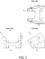
- FIG. 3 is a view showing the appearance of the bracket 5 according to the present embodiment.
- FIG. 3 shows a plan view, a lateral view, and a front view of the bracket 5.
- the appearance of the bracket 6 is the same as the appearance of the bracket 5.
- the bracket 5 may have a bottom surface support wall 51 and two side surface support walls 52.
- the bottom surface support wall 51 supports the bottom surface of the cassette 11.
- the two side surface support walls 52 support two side surfaces of the cassette 11 and face each other.
- the two side surface support walls 52 form a tapered shape that narrows toward the bottom surface of the cassette 11.
- the two side surfaces of the cassette 11 respectively contact the corresponding side surfaces of the cassette 11. Since the bracket 5 is installed below the bracket 6, it may be difficult to mount the cassette 11, but the bracket 5 has the side surface support walls 52 in a tapered shape, so the cassette 11 can be easily positioned.
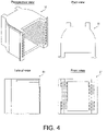
- FIG. 4 and FIG. 5 are views showing the appearance of the cassette 11 according to the present embodiment.
- FIG. 4 does not include a wafer 12.
- FIG. 5 includes the wafer 12. Both FIG. 4 and FIG. 5 show a perspective view, a plan view, a lateral view, and a front view of the cassette 11.
- a plurality of wafers 12 are inserted into the cassette 11.
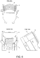
- FIG. 6 is a view showing the appearances of the bracket 5 and the cassette 11 according to the present embodiment.
- FIG. 6 shows a plan view, a lateral view, and a front view of the bracket 5 and the cassette 11.
- the appearance of the bracket 6 is the same as the appearance of the bracket 5.
- a plurality of wafers 12 are inserted into the cassette 11.
- the cassettes 11 are held obliquely instead of being arranged side by side, which allows the cassette 11 to be taken out and put in obliquely, unlike the conventional technology in which the cassette 11 is taken out from the horizontal and vertical directions. As a result, it is possible to secure a space for mounting two cassettes 11 even in a narrow space. Therefore, the mobile manipulator 1 can be introduced even in an existing factory where the width of the passage is narrow.
- a mobile manipulator includes: an unmanned transport vehicle, a robot base portion mounted on the unmanned transport vehicle, a robot arm mounted on the robot base portion, and a first mounting portion and a second mounting portion which are arranged on the robot base portion and on which a predetermined transported object is mounted.
- the first mounting portion holds the transported object in a state where a bottom surface of the transported object is inclined with respect to a horizontal, and a part of the second mounting portion overlaps on the first mounting portion in a plan view.
- the robot arm can take out the inclined transported object in the oblique direction. As a result, it is possible to secure a space for mounting two transported objects and to introduce the unmanned transporter (mobile manipulator) even in an existing factory where the width of the passage is narrow.
- the first mounting portion and the second mounting portion are arranged so as to fit inside a footprint of the unmanned transport vehicle.
- the unmanned transport vehicle moves, turns, etc. without recognizing the size of the structure mounted on the upper surface. If the structure on the upper surface protrudes from the footprint, it may collide with surrounding objects, for example, when the unmanned transport vehicle turns. According to the above configuration, since the first mounting portion and the second mounting portion fit within the footprint, it is possible to prevent the first mounting portion and the second mounting portion from colliding with surrounding objects while the unmanned transport vehicle is turning.
- the second mounting portion is arranged at a position avoiding a space in a direction perpendicular to the bottom surface of the transported object from the transported object mounted on the first mounting portion.
- the mounted object can be taken out and put in linearly in a direction perpendicular to the bottom surface (that is, the oblique direction). Therefore, there is no need for operations such as lifting up and moving laterally. In addition, it is not necessary to switch between operations such as ascending and moving laterally, and it is possible to quickly take out and put in the transported object.
- the second mounting portion holds the transported object in a state where the bottom surface of the transported object is inclined with respect to the horizontal.
- both the first mounting portion and the second mounting portion hold the transported object in a state where the bottom surface of the transported object is inclined with respect to the horizontal, the robot arm can take out and put in two transported objects in the same oblique direction at the same time.
- the first mounting portion has a bottom surface support wall that supports the bottom surface of the transported object, and two side surface support walls that support two side surfaces of the transported object and face each other, and the two side surface support walls form a tapered shape.
- the transported object having side surfaces in a corresponding tapered shape can be positioned simply by placing the transported object.
- a device in the mobile manipulator, is arranged in a space located in a lateral direction of the first mounting portion and located in a lower direction of the second mounting portion.
- the device such as a control device and an operation switch can be arranged in the space created by shifting the second mounting portion upward.
Landscapes
- Engineering & Computer Science (AREA)
- Robotics (AREA)
- Mechanical Engineering (AREA)
- Health & Medical Sciences (AREA)
- General Health & Medical Sciences (AREA)
- Orthopedic Medicine & Surgery (AREA)
- Container, Conveyance, Adherence, Positioning, Of Wafer (AREA)
- Aviation & Aerospace Engineering (AREA)
- Remote Sensing (AREA)
- Physics & Mathematics (AREA)
- General Physics & Mathematics (AREA)
- Automation & Control Theory (AREA)
- Radar, Positioning & Navigation (AREA)
- Manipulator (AREA)
- Control Of Position, Course, Altitude, Or Attitude Of Moving Bodies (AREA)
Abstract
Description
- The present invention relates to a mobile manipulator.
- At semiconductor factories, semiconductor products are manufactured based on materials that comply with the standards (hereinafter referred to as wafers) through various processes. In many cases, a person performs the work of transporting these wafers from one process to the next process with use of a device (hereinafter referred to as a cassette) that is capable of transporting several wafers as a set. However, due to labor shortage, there are many requests to automate the wafer transport work performed by people.
- [Patent Literature 1]
Japanese Patent Laid-Open No. 2001-306148 - What is important in automating the transport work (hereinafter referred to as automatic transport) is to transport two cassettes at the same time.
- When only one cassette can be transported, an unmanned transport vehicle will go to pick up the processed cassette, mount it, transport it to the next process, go to pick up a new cassette, and transport it. Therefore, it is uneconomic. However, when there is a space for transporting two cassettes at the same time, the unmanned transport vehicle can pick up the processed cassette and set a new cassette in the apparatus. Accordingly, the uneconomic issue can be reduced.
- Nevertheless, if two cassettes are mounted side by side, the size (width) of the unmanned transporter becomes large, and the swiveling radius increases.
- For the semiconductor industry in Japan, because the width of the passage in the factory is often narrow, there is a problem that the environment that can introduce an unmanned transporter is limited. If the width of the passage in the factory is increased, there is a problem that the cost rises.
- One aspect of the present invention is to mount two transported objects without increasing the width of the transport vehicle.
- In order to solve the above problems, a mobile manipulator according to one aspect of the present invention includes an unmanned transport vehicle, a robot base portion mounted on the unmanned transport vehicle, a robot arm mounted on the robot base portion, and a first mounting portion and a second mounting portion which are arranged on the robot base portion and on which a predetermined transported object is mounted. The first mounting portion holds the transported object in a state where a bottom surface of the transported object is inclined with respect to a horizontal, and a part of the second mounting portion overlaps on the first mounting portion in a plan view.
- According to one aspect of the present invention, two transported objects can be mounted without increasing the width of the transport vehicle.
-
-
FIG. 1 is a view showing the appearance of the mobile manipulator according to an embodiment of the present invention. -
FIG. 2 is a view showing the appearance of the mobile manipulator according to an embodiment of the present invention. -
FIG. 3 is a view showing the appearance of the bracket according to an embodiment of the present invention. -
FIG. 4 is a view showing the appearance of the cassette according to an embodiment of the present invention. -
FIG. 5 is a view showing the appearance of the cassette according to an embodiment of the present invention. -
FIG. 6 is a view showing the appearances of the bracket and the cassette according to an embodiment of the present invention. - Hereinafter, an embodiment according to one aspect of the present invention (hereinafter also referred to as "the present embodiment") will be described with reference to the drawings.
-
FIG. 1 andFIG. 2 are views showing the appearance of amobile manipulator 1 according to the present embodiment.FIG. 1 includes arobot arm 4.FIG. 2 does not include therobot arm 4. BothFIG. 1 andFIG. 2 show a perspective view, a plan view, a front view, and a lateral view of themobile manipulator 1. Themobile manipulator 1 transports a cassette (transported object) 11 and arranges thecassette 11 in a predetermined location. - As shown in
FIG. 1 , themobile manipulator 1 includes anunmanned transport vehicle 2, arobot base portion 3, therobot arm 4, a bracket (first mounting portion) 5, and a bracket (second mounting portion) 6. Theunmanned transport vehicle 2 is the lower half portion of the lower side of a base of therobot arm 4, and includes left andright wheels 21. Theunmanned transport vehicle 2 moves by rotating the left andright wheels 21, and changes the direction by controlling the rotation speed and the rotation direction of the left andright wheels 21. Therobot base portion 3 is the upper half portion of the lower side of the base of therobot arm 4 and is mounted on theunmanned transport vehicle 2. Therobot base portion 3 includes a controller that controls the left andright wheels 21 and therobot arm 4, a communication unit that communicates with the outside, etc. - The
robot arm 4 is mounted on therobot base portion 3 and moves the cassette (predetermined transported object) 11 between thebrackets bracket 5 and thebracket 6 are arranged on therobot base portion 3 and are mounting portions on which thecassette 11 is mounted. - As shown in the front views of
FIG. 1 andFIG. 2 , thebracket 5 holds thecassette 11 in a state where the bottom surface of thecassette 11 is inclined with respect to the horizontal. Then, as shown in the plan views and the front views ofFIG. 1 andFIG. 2 , a part of thebracket 6 overlaps on thebracket 5 in the plan view. - Further, the
bracket 6 may hold thecassette 11 in a state where the bottom surface of thecassette 11 is inclined with respect to the horizontal. - As shown in the plan view, the front view, and the lateral view of
FIG. 2 , thebrackets unmanned transport vehicle 2. The footprint is a projected area of theunmanned transport vehicle 2 in a top view, and is an area shown by the broken lines in the front view and the lateral view ofFIG. 2 . In fact, thebrackets FIG. 2 . - As shown in the front view of
FIG. 2 , thebracket 6 may be arranged at a position avoiding a space in a direction perpendicular to the bottom surface of thecassette 11 from thecassette 11 mounted on thebracket 5. That is, in the front view ofFIG. 2 , thebracket 6 is not arranged in the direction of the arrow from thebracket 5. - As a result, the
robot arm 4 can take out thecassette 11 straight from the bracket 5 (in the direction of the arrow) and insert thecassette 11 straight into thebracket 5 without being interfered by thebracket 6. - As shown in the front view of
FIG. 2 , a device 7 may be arranged in a space located in the right direction (lateral direction) of thebracket 5 and in the lower direction of thebracket 6. That is, in the front view ofFIG. 2 , since the shaded portion is located in the right direction of thebracket 5 and in the lower direction of thebracket 6, the space becomes empty. Therefore, the device 7 such as a control device and an operation switch may be arranged. -
FIG. 3 is a view showing the appearance of thebracket 5 according to the present embodiment.FIG. 3 shows a plan view, a lateral view, and a front view of thebracket 5. The appearance of thebracket 6 is the same as the appearance of thebracket 5. - As shown in
FIG. 3 , thebracket 5 may have a bottomsurface support wall 51 and two sidesurface support walls 52. At that time, the bottomsurface support wall 51 supports the bottom surface of thecassette 11. The two sidesurface support walls 52 support two side surfaces of thecassette 11 and face each other. Then, the two sidesurface support walls 52 form a tapered shape that narrows toward the bottom surface of thecassette 11. The two side surfaces of thecassette 11 respectively contact the corresponding side surfaces of thecassette 11. Since thebracket 5 is installed below thebracket 6, it may be difficult to mount thecassette 11, but thebracket 5 has the sidesurface support walls 52 in a tapered shape, so thecassette 11 can be easily positioned. -
FIG. 4 andFIG. 5 are views showing the appearance of thecassette 11 according to the present embodiment.FIG. 4 does not include awafer 12.FIG. 5 includes thewafer 12. BothFIG. 4 andFIG. 5 show a perspective view, a plan view, a lateral view, and a front view of thecassette 11. - As shown in
FIG. 5 , a plurality ofwafers 12 are inserted into thecassette 11. -
FIG. 6 is a view showing the appearances of thebracket 5 and thecassette 11 according to the present embodiment.FIG. 6 shows a plan view, a lateral view, and a front view of thebracket 5 and thecassette 11. The appearance of thebracket 6 is the same as the appearance of thebracket 5. - As shown in
FIG. 6 , a plurality ofwafers 12 are inserted into thecassette 11. - The
cassettes 11 are held obliquely instead of being arranged side by side, which allows thecassette 11 to be taken out and put in obliquely, unlike the conventional technology in which thecassette 11 is taken out from the horizontal and vertical directions. As a result, it is possible to secure a space for mounting twocassettes 11 even in a narrow space. Therefore, themobile manipulator 1 can be introduced even in an existing factory where the width of the passage is narrow. - A mobile manipulator according to one aspect of the present invention includes: an unmanned transport vehicle, a robot base portion mounted on the unmanned transport vehicle, a robot arm mounted on the robot base portion, and a first mounting portion and a second mounting portion which are arranged on the robot base portion and on which a predetermined transported object is mounted. The first mounting portion holds the transported object in a state where a bottom surface of the transported object is inclined with respect to a horizontal, and a part of the second mounting portion overlaps on the first mounting portion in a plan view.
- According to the above configuration, since a part of the second mounting portion overlaps on the first mounting portion, two transported objects can be mounted without increasing the width of the transport vehicle. Further, even though a part of the second mounting portion overlaps on the first mounting portion, the robot arm can take out the inclined transported object in the oblique direction. As a result, it is possible to secure a space for mounting two transported objects and to introduce the unmanned transporter (mobile manipulator) even in an existing factory where the width of the passage is narrow.
- In an embodiment, in the mobile manipulator, the first mounting portion and the second mounting portion are arranged so as to fit inside a footprint of the unmanned transport vehicle.
- Generally, the unmanned transport vehicle moves, turns, etc. without recognizing the size of the structure mounted on the upper surface. If the structure on the upper surface protrudes from the footprint, it may collide with surrounding objects, for example, when the unmanned transport vehicle turns. According to the above configuration, since the first mounting portion and the second mounting portion fit within the footprint, it is possible to prevent the first mounting portion and the second mounting portion from colliding with surrounding objects while the unmanned transport vehicle is turning.
- In an embodiment, in the mobile manipulator, the second mounting portion is arranged at a position avoiding a space in a direction perpendicular to the bottom surface of the transported object from the transported object mounted on the first mounting portion.
- According to the above configuration, the mounted object can be taken out and put in linearly in a direction perpendicular to the bottom surface (that is, the oblique direction). Therefore, there is no need for operations such as lifting up and moving laterally. In addition, it is not necessary to switch between operations such as ascending and moving laterally, and it is possible to quickly take out and put in the transported object.
- In an embodiment, in the mobile manipulator, the second mounting portion holds the transported object in a state where the bottom surface of the transported object is inclined with respect to the horizontal.
- According to the above configuration, since both the first mounting portion and the second mounting portion hold the transported object in a state where the bottom surface of the transported object is inclined with respect to the horizontal, the robot arm can take out and put in two transported objects in the same oblique direction at the same time.
- In an embodiment, in the mobile manipulator, the first mounting portion has a bottom surface support wall that supports the bottom surface of the transported object, and two side surface support walls that support two side surfaces of the transported object and face each other, and the two side surface support walls form a tapered shape.
- According to the above configuration, the transported object having side surfaces in a corresponding tapered shape can be positioned simply by placing the transported object.
- In an embodiment, in the mobile manipulator, a device is arranged in a space located in a lateral direction of the first mounting portion and located in a lower direction of the second mounting portion.
- According to the above configuration, the device such as a control device and an operation switch can be arranged in the space created by shifting the second mounting portion upward.
- The present invention is not limited to the embodiments described above, and various modifications can be made within the scope of the claims. The technical scope of the present invention also includes embodiments obtained by appropriately combining the technical means disclosed in different embodiments.
-
- 1 Mobile manipulator
- 2 Unmanned transport vehicle
- 3 Robot base portion
- 4 Robot arm
- 5 Bracket (first mounting portion)
- 6 Bracket (second mounting portion)
- 7 Device
- 11 Cassette (transported object)
- 12 Wafer
- 21 Wheel
- 51 Bottom surface support wall
- 52 Side surface support wall
Claims (6)
- A mobile manipulator, comprising:an unmanned transport vehicle;a robot base portion mounted on the unmanned transport vehicle;a robot arm mounted on the robot base portion; anda first mounting portion and a second mounting portion which are arranged on the robot base portion and on which a predetermined transported object is mounted,wherein the first mounting portion holds the transported object in a state where a bottom surface of the transported object is inclined with respect to a horizontal, anda part of the second mounting portion overlaps on the first mounting portion in a plan view.
- The mobile manipulator according to claim 1, wherein the first mounting portion and the second mounting portion are arranged so as to fit inside a footprint of the unmanned transport vehicle.
- The mobile manipulator according to claim 1 or 2, wherein the second mounting portion is arranged at a position avoiding a space in a direction perpendicular to the bottom surface of the transported object from the transported object mounted on the first mounting portion.
- The mobile manipulator according to any one of claims 1 to 3, wherein the second mounting portion holds the transported object in a state where the bottom surface of the transported object is inclined with respect to the horizontal.
- The mobile manipulator according to any one of claims 1 to 4, wherein the first mounting portion has a bottom surface support wall that supports the bottom surface of the transported object, and two side surface support walls that support two side surfaces of the transported object and face each other, and
the two side surface support walls form a tapered shape. - The mobile manipulator according to any one of claims 1 to 5, wherein a device is arranged in a space located in a lateral direction of the first mounting portion and located in a lower direction of the second mounting portion.
Applications Claiming Priority (2)
| Application Number | Priority Date | Filing Date | Title |
|---|---|---|---|
| JP2020032230A JP7400540B2 (en) | 2020-02-27 | 2020-02-27 | mobile manipulator |
| PCT/JP2021/004322 WO2021171965A1 (en) | 2020-02-27 | 2021-02-05 | Mobile manipulator |
Publications (2)
| Publication Number | Publication Date |
|---|---|
| EP4112233A1 true EP4112233A1 (en) | 2023-01-04 |
| EP4112233A4 EP4112233A4 (en) | 2024-03-27 |
Family
ID=77490481
Family Applications (1)
| Application Number | Title | Priority Date | Filing Date |
|---|---|---|---|
| EP21760823.1A Withdrawn EP4112233A4 (en) | 2020-02-27 | 2021-02-05 | Mobile manipulator |
Country Status (6)
| Country | Link |
|---|---|
| US (1) | US12296472B2 (en) |
| EP (1) | EP4112233A4 (en) |
| JP (1) | JP7400540B2 (en) |
| KR (1) | KR102681748B1 (en) |
| CN (1) | CN115003458A (en) |
| WO (1) | WO2021171965A1 (en) |
Families Citing this family (1)
| Publication number | Priority date | Publication date | Assignee | Title |
|---|---|---|---|---|
| JP7537075B2 (en) * | 2019-07-09 | 2024-08-21 | セイコーエプソン株式会社 | Mobile robot |
Family Cites Families (19)
| Publication number | Priority date | Publication date | Assignee | Title |
|---|---|---|---|---|
| US4698775A (en) * | 1985-05-17 | 1987-10-06 | Flexible Manufacturing Systems, Inc. | Self-contained mobile reprogrammable automation device |
| JPH0469713A (en) * | 1990-07-11 | 1992-03-04 | Hitachi Ltd | Self-traveling truck and semiconductor manufacturing line |
| JPH04189483A (en) | 1990-11-21 | 1992-07-07 | Hitachi Ltd | Carrying robot for wafer storing jig |
| JPH05190648A (en) * | 1992-01-13 | 1993-07-30 | Hitachi Ltd | Transfer method of wafer containing jig |
| JPH06218678A (en) * | 1993-01-26 | 1994-08-09 | Hitachi Ltd | A trolley with a position / posture conversion mechanism |
| JPH0851136A (en) | 1994-08-05 | 1996-02-20 | Takenaka Komuten Co Ltd | Semiconductor manufacturing equipment |
| JP2000252686A (en) | 1999-03-02 | 2000-09-14 | Matsushita Electric Ind Co Ltd | Electronic component mounting equipment |
| JP2001306148A (en) | 2000-04-19 | 2001-11-02 | Murata Mach Ltd | Automatic guided vehicle with robot and its system |
| JP2002286091A (en) | 2001-03-26 | 2002-10-03 | Murata Mach Ltd | Article mount and conveyor system equipped therewith |
| JP2004281475A (en) | 2003-03-12 | 2004-10-07 | Seiko Epson Corp | Single wafer transfer device and single wafer transfer method |
| NO2966067T3 (en) * | 2013-08-12 | 2018-03-24 | ||
| MX364080B (en) | 2013-09-09 | 2019-04-11 | Dematic Corp | Autonomous mobile picking. |
| KR101869813B1 (en) | 2013-10-28 | 2018-06-21 | 무라다기카이가부시끼가이샤 | Conveyor device |
| JP6470763B2 (en) * | 2014-12-26 | 2019-02-13 | 川崎重工業株式会社 | Production system |
| JP6587814B2 (en) | 2015-02-27 | 2019-10-09 | シャープ株式会社 | Autonomous robot |
| JP6510436B2 (en) | 2016-02-12 | 2019-05-08 | 株式会社日立製作所 | Article conveying system, conveying apparatus and article conveying method |
| US10343881B2 (en) | 2017-04-24 | 2019-07-09 | Ching Qing Guo | Automatic batch picking robot |
| WO2019133944A1 (en) * | 2017-12-29 | 2019-07-04 | Avar Robotics Inc. | Robotic item retrieval and distribution system |
| US11235930B2 (en) * | 2018-03-20 | 2022-02-01 | Bastian Solutions, Llc | Robotic shuttle system |
-
2020
- 2020-02-27 JP JP2020032230A patent/JP7400540B2/en active Active
-
2021
- 2021-02-05 EP EP21760823.1A patent/EP4112233A4/en not_active Withdrawn
- 2021-02-05 KR KR1020227023079A patent/KR102681748B1/en active Active
- 2021-02-05 US US17/793,031 patent/US12296472B2/en active Active
- 2021-02-05 CN CN202180008124.2A patent/CN115003458A/en active Pending
- 2021-02-05 WO PCT/JP2021/004322 patent/WO2021171965A1/en not_active Ceased
Also Published As
| Publication number | Publication date |
|---|---|
| EP4112233A4 (en) | 2024-03-27 |
| JP7400540B2 (en) | 2023-12-19 |
| US12296472B2 (en) | 2025-05-13 |
| KR102681748B1 (en) | 2024-07-04 |
| WO2021171965A1 (en) | 2021-09-02 |
| US20230044274A1 (en) | 2023-02-09 |
| JP2021133466A (en) | 2021-09-13 |
| KR20220110279A (en) | 2022-08-05 |
| CN115003458A (en) | 2022-09-02 |
Similar Documents
| Publication | Publication Date | Title |
|---|---|---|
| JP6760386B2 (en) | Ceiling transfer system and overhead transfer vehicle | |
| KR100880291B1 (en) | Access to one or more levels of material storage shelves by an overhead hoist transport vehicle from a single track position | |
| US20070186799A1 (en) | Direction change device | |
| EP2790210A2 (en) | Automated material handling system | |
| US8875866B2 (en) | Article transport facility | |
| KR20010006331A (en) | Integrated intrabay buffer, delivery, and stocker system | |
| TW201810496A (en) | Transport system | |
| KR20160134507A (en) | Container transport device and container transport facility | |
| CN104909101A (en) | Container Transport Facility | |
| JPWO2006046580A1 (en) | Transfer system, substrate processing apparatus, and transfer method | |
| US12296472B2 (en) | Mobile manipulator | |
| TWI829780B (en) | Loading system | |
| CN1216285A (en) | Stocking equipment including port with operating unit | |
| JP5928304B2 (en) | Board transfer equipment | |
| US11820593B2 (en) | Transport vehicle system | |
| KR20010014928A (en) | Manufacturing plant for semiconductor products | |
| KR101612414B1 (en) | System for transferring product | |
| JP7195127B2 (en) | Positioning method of transport unit and transport tray | |
| JPH05190648A (en) | Transfer method of wafer containing jig | |
| JP2007208284A (en) | Vacuum processing method in vacuum processing apparatus | |
| KR20240098700A (en) | Autonomous vehicle and carrier transport system including the same | |
| CN120149251A (en) | Support unit and container storage system including the support unit | |
| KR20220060485A (en) | Transport vehicle | |
| JPH05129416A (en) | Wafer storage jig transfer method | |
| KR20180071082A (en) | Apparatus for rotating semiconductor wafer carrier |
Legal Events
| Date | Code | Title | Description |
|---|---|---|---|
| STAA | Information on the status of an ep patent application or granted ep patent |
Free format text: STATUS: THE INTERNATIONAL PUBLICATION HAS BEEN MADE |
|
| PUAI | Public reference made under article 153(3) epc to a published international application that has entered the european phase |
Free format text: ORIGINAL CODE: 0009012 |
|
| STAA | Information on the status of an ep patent application or granted ep patent |
Free format text: STATUS: REQUEST FOR EXAMINATION WAS MADE |
|
| 17P | Request for examination filed |
Effective date: 20220708 |
|
| AK | Designated contracting states |
Kind code of ref document: A1 Designated state(s): AL AT BE BG CH CY CZ DE DK EE ES FI FR GB GR HR HU IE IS IT LI LT LU LV MC MK MT NL NO PL PT RO RS SE SI SK SM TR |
|
| DAV | Request for validation of the european patent (deleted) | ||
| DAX | Request for extension of the european patent (deleted) | ||
| A4 | Supplementary search report drawn up and despatched |
Effective date: 20240223 |
|
| RIC1 | Information provided on ipc code assigned before grant |
Ipc: B25J 11/00 20060101ALN20240219BHEP Ipc: B25J 9/16 20060101ALI20240219BHEP Ipc: B25J 5/00 20060101AFI20240219BHEP |
|
| STAA | Information on the status of an ep patent application or granted ep patent |
Free format text: STATUS: THE APPLICATION HAS BEEN WITHDRAWN |
|
| 18W | Application withdrawn |
Effective date: 20251124 |