EP4112153A1 - Gas-liquid separator - Google Patents
Gas-liquid separator Download PDFInfo
- Publication number
- EP4112153A1 EP4112153A1 EP20920780.2A EP20920780A EP4112153A1 EP 4112153 A1 EP4112153 A1 EP 4112153A1 EP 20920780 A EP20920780 A EP 20920780A EP 4112153 A1 EP4112153 A1 EP 4112153A1
- Authority
- EP
- European Patent Office
- Prior art keywords
- gas
- body portion
- liquid separator
- straightening plate
- liquid
- Prior art date
- Legal status (The legal status is an assumption and is not a legal conclusion. Google has not performed a legal analysis and makes no representation as to the accuracy of the status listed.)
- Granted
Links
Images




Classifications
-
- B—PERFORMING OPERATIONS; TRANSPORTING
- B01—PHYSICAL OR CHEMICAL PROCESSES OR APPARATUS IN GENERAL
- B01D—SEPARATION
- B01D45/00—Separating dispersed particles from gases or vapours by gravity, inertia, or centrifugal forces
- B01D45/12—Separating dispersed particles from gases or vapours by gravity, inertia, or centrifugal forces by centrifugal forces
- B01D45/16—Separating dispersed particles from gases or vapours by gravity, inertia, or centrifugal forces by centrifugal forces generated by the winding course of the gas stream, the centrifugal forces being generated solely or partly by mechanical means, e.g. fixed swirl vanes
-
- F—MECHANICAL ENGINEERING; LIGHTING; HEATING; WEAPONS; BLASTING
- F04—POSITIVE - DISPLACEMENT MACHINES FOR LIQUIDS; PUMPS FOR LIQUIDS OR ELASTIC FLUIDS
- F04B—POSITIVE-DISPLACEMENT MACHINES FOR LIQUIDS; PUMPS
- F04B39/00—Component parts, details, or accessories, of pumps or pumping systems specially adapted for elastic fluids, not otherwise provided for in, or of interest apart from, groups F04B25/00 - F04B37/00
- F04B39/16—Filtration; Moisture separation
-
- B—PERFORMING OPERATIONS; TRANSPORTING
- B01—PHYSICAL OR CHEMICAL PROCESSES OR APPARATUS IN GENERAL
- B01D—SEPARATION
- B01D45/00—Separating dispersed particles from gases or vapours by gravity, inertia, or centrifugal forces
- B01D45/02—Separating dispersed particles from gases or vapours by gravity, inertia, or centrifugal forces by utilising gravity
-
- B—PERFORMING OPERATIONS; TRANSPORTING
- B01—PHYSICAL OR CHEMICAL PROCESSES OR APPARATUS IN GENERAL
- B01D—SEPARATION
- B01D45/00—Separating dispersed particles from gases or vapours by gravity, inertia, or centrifugal forces
- B01D45/04—Separating dispersed particles from gases or vapours by gravity, inertia, or centrifugal forces by utilising inertia
- B01D45/08—Separating dispersed particles from gases or vapours by gravity, inertia, or centrifugal forces by utilising inertia by impingement against baffle separators
-
- B—PERFORMING OPERATIONS; TRANSPORTING
- B01—PHYSICAL OR CHEMICAL PROCESSES OR APPARATUS IN GENERAL
- B01D—SEPARATION
- B01D45/00—Separating dispersed particles from gases or vapours by gravity, inertia, or centrifugal forces
- B01D45/12—Separating dispersed particles from gases or vapours by gravity, inertia, or centrifugal forces by centrifugal forces
-
- B—PERFORMING OPERATIONS; TRANSPORTING
- B04—CENTRIFUGAL APPARATUS OR MACHINES FOR CARRYING-OUT PHYSICAL OR CHEMICAL PROCESSES
- B04C—APPARATUS USING FREE VORTEX FLOW, e.g. CYCLONES
- B04C5/00—Apparatus in which the axial direction of the vortex is reversed
- B04C5/02—Construction of inlets by which the vortex flow is generated, e.g. tangential admission, the fluid flow being forced to follow a downward path by spirally wound bulkheads, or with slightly downwardly-directed tangential admission
- B04C5/04—Tangential inlets
-
- B—PERFORMING OPERATIONS; TRANSPORTING
- B04—CENTRIFUGAL APPARATUS OR MACHINES FOR CARRYING-OUT PHYSICAL OR CHEMICAL PROCESSES
- B04C—APPARATUS USING FREE VORTEX FLOW, e.g. CYCLONES
- B04C5/00—Apparatus in which the axial direction of the vortex is reversed
- B04C5/08—Vortex chamber constructions
- B04C5/103—Bodies or members, e.g. bulkheads, guides, in the vortex chamber
-
- B—PERFORMING OPERATIONS; TRANSPORTING
- B04—CENTRIFUGAL APPARATUS OR MACHINES FOR CARRYING-OUT PHYSICAL OR CHEMICAL PROCESSES
- B04C—APPARATUS USING FREE VORTEX FLOW, e.g. CYCLONES
- B04C5/00—Apparatus in which the axial direction of the vortex is reversed
- B04C5/14—Construction of the underflow ducting; Apex constructions; Discharge arrangements ; discharge through sidewall provided with a few slits or perforations
- B04C5/15—Construction of the underflow ducting; Apex constructions; Discharge arrangements ; discharge through sidewall provided with a few slits or perforations with swinging flaps or revolving sluices; Sluices; Check-valves
-
- F—MECHANICAL ENGINEERING; LIGHTING; HEATING; WEAPONS; BLASTING
- F04—POSITIVE - DISPLACEMENT MACHINES FOR LIQUIDS; PUMPS FOR LIQUIDS OR ELASTIC FLUIDS
- F04B—POSITIVE-DISPLACEMENT MACHINES FOR LIQUIDS; PUMPS
- F04B39/00—Component parts, details, or accessories, of pumps or pumping systems specially adapted for elastic fluids, not otherwise provided for in, or of interest apart from, groups F04B25/00 - F04B37/00
- F04B39/04—Measures to avoid lubricant contaminating the pumped fluid
-
- F—MECHANICAL ENGINEERING; LIGHTING; HEATING; WEAPONS; BLASTING
- F04—POSITIVE - DISPLACEMENT MACHINES FOR LIQUIDS; PUMPS FOR LIQUIDS OR ELASTIC FLUIDS
- F04C—ROTARY-PISTON, OR OSCILLATING-PISTON, POSITIVE-DISPLACEMENT MACHINES FOR LIQUIDS; ROTARY-PISTON, OR OSCILLATING-PISTON, POSITIVE-DISPLACEMENT PUMPS
- F04C29/00—Component parts, details or accessories of pumps or pumping installations, not provided for in groups F04C18/00 - F04C28/00
- F04C29/02—Lubrication; Lubricant separation
-
- F—MECHANICAL ENGINEERING; LIGHTING; HEATING; WEAPONS; BLASTING
- F25—REFRIGERATION OR COOLING; COMBINED HEATING AND REFRIGERATION SYSTEMS; HEAT PUMP SYSTEMS; MANUFACTURE OR STORAGE OF ICE; LIQUEFACTION SOLIDIFICATION OF GASES
- F25B—REFRIGERATION MACHINES, PLANTS OR SYSTEMS; COMBINED HEATING AND REFRIGERATION SYSTEMS; HEAT PUMP SYSTEMS
- F25B43/00—Arrangements for separating or purifying gases or liquids; Arrangements for vaporising the residuum of liquid refrigerant, e.g. by heat
- F25B43/02—Arrangements for separating or purifying gases or liquids; Arrangements for vaporising the residuum of liquid refrigerant, e.g. by heat for separating lubricants from the refrigerant
-
- F—MECHANICAL ENGINEERING; LIGHTING; HEATING; WEAPONS; BLASTING
- F04—POSITIVE - DISPLACEMENT MACHINES FOR LIQUIDS; PUMPS FOR LIQUIDS OR ELASTIC FLUIDS
- F04C—ROTARY-PISTON, OR OSCILLATING-PISTON, POSITIVE-DISPLACEMENT MACHINES FOR LIQUIDS; ROTARY-PISTON, OR OSCILLATING-PISTON, POSITIVE-DISPLACEMENT PUMPS
- F04C29/00—Component parts, details or accessories of pumps or pumping installations, not provided for in groups F04C18/00 - F04C28/00
- F04C29/02—Lubrication; Lubricant separation
- F04C29/026—Lubricant separation
-
- F—MECHANICAL ENGINEERING; LIGHTING; HEATING; WEAPONS; BLASTING
- F25—REFRIGERATION OR COOLING; COMBINED HEATING AND REFRIGERATION SYSTEMS; HEAT PUMP SYSTEMS; MANUFACTURE OR STORAGE OF ICE; LIQUEFACTION SOLIDIFICATION OF GASES
- F25B—REFRIGERATION MACHINES, PLANTS OR SYSTEMS; COMBINED HEATING AND REFRIGERATION SYSTEMS; HEAT PUMP SYSTEMS
- F25B2400/00—Component parts or details not otherwise provided for in this subclass
- F25B2400/02—Centrifugal separation of gas, liquid or oil
Definitions
- the present invention relates to a gas-liquid separator that separates gas and liquid from a gas-liquid mixture.
- lubricating oil liquid
- gas such as air or gas suctioned into the compressor. Accordingly, lubricating oil is present in a mixed state in the gas ejected from the compressor.
- Patent Literature 1 described below discloses a gas-liquid separator that centrifuges gas and liquid by blowing a gas-liquid mixture into a body portion having a cylindrical shape.
- a guide plate having a curved shape is attached to a gas-liquid separator body (body portion), being a pressure vessel having a cylindrical shape, with a predetermined distance between an inner wall of the body portion and the guide plate to form a guide path between the inner wall of the body portion and the guide plate, thus causing a gas-liquid mixture to swirl in a long-distance receiver tank.
- Patent Literature 1 JP 2004-52710 A
- the guide plate is formed to have a shape where the distance between the guide plate and the inner wall of the body portion gradually increases within a range of a predetermined length from one end toward the other end side of the guide plate and hence, a flow velocity of a gas-liquid mixture that flows into the body portion decreases in the guide path.
- the flow velocity of the gas-liquid mixture decreases, there may be a case where the gas-liquid mixture does not sufficiently swirl in the body portion, so that there is a possibility that gas and liquid cannot be suitably separated.
- an introduction passage is attached to the body portion in a state of being parallel to a tangent with respect to an outer wall of the body portion and of being disposed at a position close to the tangent. Accordingly, it is difficult to attach the introduction passage in manufacture, and the number of work steps increases.
- the present invention has been made to solve the above-mentioned problems, and it is an object of the present invention to provide a small-sized or compact gas-liquid separator that can suitably separate gas and liquid by increasing the flow velocity of the gas-liquid mixture that flows into the body portion.
- a gas-liquid separator that achieves the above-mentioned object is a gas-liquid separator that separates gas and liquid from a gas-liquid mixture.
- the gas-liquid separator includes: a body portion having a cylindrical shape; an introduction passage provided in a state of communicating with the body portion, the gas-liquid mixture being introduced through the introduction passage; a straightening plate attached to the body portion to extend in a chord length direction of a circular arc formed at a barrel of the body portion, the straightening plate being configured to straighten the gas-liquid mixture; and an exhaust flow passage provided for gas from which liquid is separated.
- the straightening plate has a narrow width portion configured such that a distance between the straightening plate and an inner wall of the body portion gradually decreases toward an end portion from which the gas-liquid mixture flows out.
- a swirl portion in the body portion is formed by the body portion extending in an up-and-down direction and a partition plate.
- the straightening plate has the narrow width portion configured such that the distance between the straightening plate and the inner wall of the body portion gradually decreases toward the end portion from which the gas-liquid mixture flows out. Accordingly, it is possible to increase a flow velocity of the gas-liquid mixture and it is possible to effectively make use of a space in the barrel and hence, gas and liquid can be suitably separated.
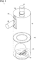
- Figure 1 is a schematic transparent view showing a gas-liquid separator 1 according to an embodiment of the present invention.
- Figure 2 is a schematic vertical cross-sectional view showing the gas-liquid separator 1 according to this embodiment.
- Figure 3 is a diagram taken along a line A-A and seen from a direction indicated by arrows in Figure 2 , the diagram showing the gas-liquid separator 1 according to this embodiment.
- Figure 4 is a diagram for describing a configuration of a straightening plate 50 of the gas-liquid separator 1 according to this embodiment.
- the gas-liquid separator 1 includes a body portion 10, an introduction passage 20, an exhaust flow passage 30, an oil discharge flow passage 40, the straightening plate 50, and a partition plate 60, the body portion 10 having a cylindrical shape, a gas-liquid mixture being introduced through the introduction passage 20, gas being exhausted through the exhaust flow passage 30, a refrigerating machine oil being discharged through the oil discharge flow passage 40, the straightening plate 50 straightening the gas-liquid mixture, and the partition plate 60 being provided at a position lower than the introduction passage 20.
- the gas-liquid separator 1 is used for a gas compressor, is preferably used for a high-speed multicylinder refrigerating machine, and is more preferably used for a high-speed multicylinder refrigerating machine for ship.
- the gas-liquid separator 1 is used for returning oil accompanied by a compressed gas to a crankcase.
- the body portion 10 is formed into a cylindrical shape extending in an up-and-down direction.
- a conical funnel is provided at a lower portion or a configuration in which a swirl flow is generated by using a gas outflow pipe as an inner cylinder
- there is no inner cylinder forming a resistance against a swirl flow is not provided and hence, the swirl flow is efficiently formed only by the cylindrical shape.
- the partition plate 60 it is possible to narrow a swirl region R (see Figure 2 ). Therefore, by increasing a swirl speed without dispersing the swirl flow, it is possible to improve a separation efficiency.
- the body portion 10 is formed of a steel pipe, for example, the body portion 10 is not limited to the steel pipe.
- the size of the body portion 10 is not particularly limited, it is preferable to set the size of the body portion 10 to a size that allows gas and liquid to be suitably separated. Specifically, it is preferable to set the size of the body portion 10 to a volume that allows a gas-liquid mixture to have a retention time of 0.6 seconds or more.
- the straightening plate 50 is disposed to extend in a chord length direction of a circular arc formed at a barrel of the body portion 10 when viewed from above.
- One end of the straightening plate 50 is connected to an inner wall of the body portion 10, and the other end of the straightening plate 50 has an end portion 50A.
- the straightening plate 50 has a narrow width portion configured such that a distance between the straightening plate 50 and the inner wall of the body portion 10 gradually decreases.
- the introduction passage 20 is provided in a state of communicating with the body portion 10.
- the introduction passage 20 is provided as shown in Figure 3 .
- the introduction passage 20 is provided at a free angle with respect to a center of the body portion 10 within a range of a circular arc formed with a length corresponding to 1/4 or less (90° or less shown in Figure 3 ) of a circumference of the barrel of the body portion 10.
- the introduction passage 20 is attached to extend in a tangential direction with respect to the body portion 10, for example, it is difficult to form a distorted hole in the body portion 10 and to weld the introduction passage 20 to the body portion 10.
- the introduction passage 20 is provided at the free angle and with a free offset amount with respect to the center of the body portion 10 and hence, it is possible to easily weld the introduction passage 20 to the body portion 10.
- the exhaust flow passage 30 is provided at an upper portion of the body portion 10. Gas (gas) separated from a refrigerating machine oil (liquid) is exhausted through the exhaust flow passage 30.
- an insertion portion of the exhaust flow passage 30 is configured to extend downward a short distance from an upper end portion 10A of the body portion 10.
- the exhaust flow passage 30 has no insertion portion and is configured to extend upward from the upper end portion 10A, and the introduction passage 20 and the exhaust flow passage 30 are disposed close to each other.
- the introduction passage 20 and the exhaust flow passage 30 are disposed close to each other.
- the gas-liquid separator 1 is configured such that the insertion portion of the exhaust flow passage 30 extends downward in a short distance from the upper end portion 10A of the body portion 10. Accordingly, of a gas-liquid mixture that flows out from the end portion 50A of the straightening plate 50, an unseparated gas that is discharged to an outer peripheral region of the insertion portion in a space above the straightening plate 50 or refrigerating machine oil separated from the gas is prevented from directly flowing into the exhaust flow passage 30 and hence, it is possible to suitably suppress a situation where the unseparated gas or the refrigerating machine oil is discharged to the outside.
- a lower portion of the body portion 10 forms an oil storage portion.
- the oil discharge flow passage 40 is provided at the lower portion of the body portion 10. Refrigerating machine oil separated from gas is discharged through the oil discharge flow passage 40.
- a float valve 90 is disposed above the oil discharge flow passage 40. The float valve 90 has a known configuration and hence, the detailed description of the float valve 90 will be omitted.
- the straightening plate 50 causes a gas-liquid mixture introduced through the introduction passage 20 to be subject to impingement separation and changes a flow direction to a circumferential direction to straighten the flow. At the same time, the straightening plate 50 increases a flow velocity of the gas-liquid mixture introduced through the introduction passage 20.
- the straightening plate 50 is fixed to an inner wall of an inflow portion formed in the inside of the body portion 10.
- the straightening plate 50 includes the first extending portion 51, a second extending portion 52, and a third extending portion 53, the first extending portion 51 extending inward in the substantially horizontal direction from an inner wall of the body portion 10, the second extending portion 52 being continuously formed with the first extending portion 51 and extending in a downward direction, the third extending portion 53 being continuously formed with the second extending portion 52 and extending to the inner wall of the body portion 10.
- the straightening plate 50 is attached to extend along an X-Y line, that is, to extend in a chord length direction of a circular arc formed with a length corresponding to 1/4 or less (90° or less shown in Figure 3 ) of the circumference of the barrel of the body portion 10.
- the straightening plate 50 is formed into a square U shape or a U shape when viewed in a front view.
- the straightening plate 50 may be formed as an integral body by the first extending portion 51, the second extending portion 52, and the third extending portion 53.
- the first extending portion 51 and the third extending portion 53 are fixed to the inner wall of the body portion 10 by welding, for example.
- the straightening plate 50 may be integrally formed with the inner wall of the body portion 10. As described above, the first extending portion 51 does not vary the shape of a narrow width portion 54 with respect to the body portion 10 and hence, it is possible to prevent breakage of the straightening plate 50 or a reduction in service life of the straightening plate 50. As shown in Figure 3 , the straightening plate 50 extends to cover the introduction passage 20 such that a gas-liquid mixture introduced through the introduction passage 20 impinges on the straightening plate 50.
- Figure 3 shows one straightening plate 50 that has both a function of an impingement separation portion and a function of a flow direction straightening portion.
- the flow direction straightening portion may be formed by the straightening plate 50 where the flow passage is narrowed toward the narrow width portion 54.
- the narrow width portion 54 has a narrow flow passage toward an internal opening.
- the narrow width portion 54 generates a swirl flow in the inside of the barrel while ensuring a gas flow velocity suitable for centrifugation.
- the narrow width portion 54 also has a function of causing the gas-liquid mixture to diagonally impinge on a flow swirling in the barrel so as to prevent the gas-liquid mixture from opposing the flow swirling in the barrel.
- the first extending portion 51 is formed to have a linear shape when viewed from above and when viewed in a front view.
- the second extending portion 52 is also formed to have a linear shape when viewed in a front view.
- the first extending portion 51 and the third extending portion 53 are fixed to the inner wall of the body portion 10 at positions above and below the introduction passage 20 and hence, the first extending portion 51 and the third extending portion 53 act as baffle plates. Accordingly, it is possible to suitably suppress a situation where, of the gas-liquid mixture introduced through the introduction passage 20, refrigerating machine oil is discharged through the exhaust flow passage 30.
- the first extending portion 51 and the third extending portion 53 of the straightening plate 50 have the narrow width portion 54 configured such that a distance between the straightening plate 50 and the inner wall of the body portion 10 gradually decreases toward the end portion 50A when viewed from above, the gas-liquid mixture flowing out from the end portion 50A. That is, in the vicinity of the narrow width portion 54, the straightening plate 50 gradually approaches the inner wall of the body portion 10 toward the end portion 50A of the first extending portion 51 and the third extending portion 53. As shown in Figure 3 , the straightening plate 50 is formed to have a linear shape when viewed from above.
- Such a configuration it is possible to increase a flow velocity of the gas-liquid mixture and hence, gas and liquid can be separated more suitably. Further, such a configuration does not require a guide plate and a guide path that are formed in the circumferential direction for approximately half of the circumference, the guide plate and the guide path being disclosed in JP 2004-52710 A . Accordingly, a simple configuration can be achieved.
- the flow velocity of the gas-liquid mixture in the introduction passage 20 is 4 m/s to 10 m/s, for example, the flow velocity of the gas-liquid mixture at the end portion 50A of the straightening plate 50 is 6 m/s to 15 m/s.
- the partition plate 60 is provided at a position lower than the introduction passage 20.
- the partition plate 60 is connected to the inner wall of the body portion 10.
- the partition plate 60 has a small inner diameter, thus having an inner diameter of a so-called toroidal shape.
- the inner diameter of the partition plate 60 is not particularly limited, the inner diameter of the partition plate 60 is 0.4 to 0.6 times the inner diameter of the body portion 10.
- the partition plate 60 is formed separately from the body portion 10.
- the partition plate 60 is fixed to the body portion 10 by welding, for example.
- the partition plate 60 is formed along an XY plane . That is, the partition plate 60 is configured to be substantially horizontal without being inclined with respect to the gas-liquid separator 1.
- the partition plate 60 is provided along the horizontal direction as described above and hence, it is possible to easily manufacture the gas-liquid separator 1.
- the swirl region R (see Figure 2 ) extending along the up-and-down direction is narrowed and hence, it is possible to increase a swirl speed. Accordingly, it is possible to suitably separate gas and liquid.
- the partition plate 60 is disposed at a position sufficiently away from the exhaust flow passage 30.
- oil adhering to the inner wall of the body portion 10 due to the swirl flow of the gas-liquid mixture is gravitationally precipitated and temporarily stays on the partition plate 60, and then descends to the oil discharge flow passage 40 from an opening portion of the partition plate 60 without flowing out through the exhaust flow passage 30, the oil discharge flow passage 40 being disposed at a position lower than the opening portion of the partition plate 60.
- the introduced gas-liquid mixture flows between the inner wall of the body portion 10 and the straightening plate 50 and flows out from the end portion 50A of the straightening plate 50.
- the straightening plate 50 has the narrow width portion 54 and hence, the gas-liquid mixture flows out from the end portion 50A of the straightening plate 50 at an increased flow velocity.
- the gas-liquid mixture that flows out from the end portion 50A of the straightening plate 50 swirls along the inner wall of the body portion 10, so that gas and liquid are centrifuged (see Figure 3 ).
- the gas-liquid separator 1 is the gas-liquid separator 1 that separates gas and liquid from a gas-liquid mixture.
- the gas-liquid separator 1 includes the body portion 10, the introduction passage 20, the straightening plate 50, and the exhaust flow passage 30, the body portion 10 having a cylindrical shape, the introduction passage 20 being provided in a state of communicating with the body portion 10, the gas-liquid mixture being introduced through the introduction passage 20, the straightening plate 50 being attached to the body portion 10 and straightening the gas-liquid mixture to increase a flow velocity, and the exhaust flow passage 30 being provided for gas from which liquid is separated.
- the straightening plate 50 is attached to extend in the chord length direction of the circular arc formed with the length corresponding to 1/4 or less (90° or less as shown in Figure 3 ) of the circumference of the barrel of the body portion 10.
- the introduction passage 20 is connected at a free angle and a free offset amount within a range of the circular arc.
- the straightening plate 50 has the narrow width portion 54 configured such that a distance between the straightening plate 50 and the inner wall of the body portion 10 gradually decreases toward the end portion 50A from which the gas-liquid mixture flows out.
- the straightening plate 50 has the narrow width portion 54 configured such that the distance between the straightening plate 50 and the inner wall of the body portion 10 gradually decreases toward the end portion 50A from which the gas-liquid mixture flows out. Accordingly, it is possible to suitably separate gas and liquid by increasing the flow velocity of the gas-liquid mixture.
- the straightening plate 50 is formed to have a linear shape when viewed from above. For the gas-liquid separator 1 having such a configuration, it is possible to easily manufacture the straightening plate 50.
- the straightening plate 50 When viewed in a front view, the straightening plate 50 is fixed to the inner wall of the body portion 10 at a position higher than the introduction passage 20.
- the gas-liquid separator 1 having such a configuration, it is possible to suitably suppress a situation where, of a gas-liquid mixture that flows out from the end portion 50A of the straightening plate 50, refrigerating machine oil separated from gas is discharged through the exhaust flow passage 30.
- the gas-liquid separator 1 further includes the partition plate 60 provided at a position lower than the introduction passage 20 and having the inner diameter of a toroidal shape which is smaller than the inner diameter of the body portion 10.
- the partition plate 60 provided at a position lower than the introduction passage 20 and having the inner diameter of a toroidal shape which is smaller than the inner diameter of the body portion 10.
- the partition plate 60 is provided along the horizontal direction.
- gas-liquid separator 1 having such a configuration it is possible to easily form the partition plate 60.
- Gas fluid from which oil is separated rises at the center of the swirl flow from the partition plate 60 toward the exhaust flow passage 30.
- the gas-liquid separator 1 having such a configuration does not require the tapered portion of the barrel which is provided at the lower portion of a conventional barrel, thus contributing to achieving a compact configuration.
- the straightening plate 50 includes the first extending portion 51, the second extending portion 52, and the third extending portion 53 and is formed into a square U shape, the first extending portion 51 extending substantially horizontally inward from the inner wall of the body portion 10, the second extending portion 52 being formed continuously with the first extending portion 51 and extending in the downward direction, the third extending portion 53 being formed continuously with the second extending portion 52 and extending to the inner wall of the body portion 10.
- a straightening plate 150 may be formed into an L shape including a first extending portion 151 and a second extending portion 152, the first extending portion 151 extending substantially horizontally inward from the inner wall of the body portion, the second extending portion 152 being formed continuously with the first extending portion 151 and extending in the downward direction.
- the partition plate 60 is provided along the horizontal direction.
- a partition plate 160 may be configured to be inclined inward in the radial direction and in the downward direction. With such a configuration, it is possible to cause refrigerating machine oil on the partition plate 160 to descend downward along an inclined surface and hence, it is possible to suitably suppress a situation where the refrigerating machine oil is stored on the partition plate 160.
- the straightening plate 50 is formed to have a linear shape when viewed from above.
- the configuration of the straightening plate is not limited to the configuration that has the narrow width portion configured such that the distance between the straightening plate and the inner wall of the body portion gradually decreases toward the end portion from which a gas-liquid mixture flows out.
- the straightening plate 50 may be formed to have a curved shape, for example.
- the gas-liquid separator 1 includes the partition plate 60 having a toroidal shape. However, it is not always necessary for the gas-liquid separator 1 to include the partition plate having a toroidal shape.
- the gas-liquid separator 1 includes the partition plate 60 having a toroidal shape.
- a gas-liquid separator 2 may include a partition plate 260 that partitions the body portion 10 into an upper portion and a lower portion in place of the partition plate 60 having a toroidal shape.
- the partition plate 260 has a through hole 261 at an end portion, the through hole 261 penetrating through the partition plate 260 in the up-and-down direction.
- a size of the through hole 261 is not particularly limited, when the inner diameter of the body portion 10 is 150 to 160 mm, the size of the through hole 261 is 15 mm ⁇ 15 mm, for example.
- a demister 360 may be attached to the partition plate 60.
- a method for attaching the demister 360 to the partition plate 60 is not particularly limited.
- the demister 360 is not particularly limited, a demister made of SUS304 and having a wire diameter of 0.12 mm and a density of 360kg/m3 may be used for the demister 360.
- the demister 360 is attached to a lower side of the partition plate 60.
- the demister 360 may be attached to an upper side of the partition plate 60, or may be attached in a state of being sandwiched between the partition plates 60.
- the demister 360 can suitably attenuate a swirl flow of a gas-liquid mixture and hence, it is possible to reduce violent movement of the float valve 90 and movement of an oil surface.
- Figure 11 shows the results obtained by measuring a separation efficiency and a pressure loss when a flow velocity of a gas-liquid mixture introduced into the gas-liquid separator 1 having the above-mentioned configuration through the introduction passage 20 is changed within a range of 5 to 20 m/s.
- the horizontal axis shows the flow velocity of the gas-liquid mixture
- black circles on the vertical axis show the separation efficiency
- white circles on the vertical axis show the pressure loss.
- a separation efficiency of 97% or more can be ensured at every flow velocity.
- the pressure loss increases with an increase in flow velocity of the gas-liquid mixture, it is found that a maximum pressure loss is 5kPa, which is not an especially high numerical value.
- gas that flows into the body portion 10 through the introduction passage 20 is subject to impingement separation at the straightening plate 50 and, then, a gas-liquid mixture that flows out from the end portion 50A of the straightening plate 50 swirls along the inner wall of the body portion 10, so that gas and liquid are centrifuged.
- a gas-liquid mixture that flows out from the end portion 50A of the straightening plate 50 swirls along the inner wall of the body portion 10, so that gas and liquid are centrifuged.
- the gas-liquid separator 1 can be used as an oil separator of a gas compressor, can be suitably used for a high-speed multicylinder refrigerating machine, and can be more suitably used for a high-speed multicylinder refrigerating machine for ship having a restriction on a mounting space.
Landscapes
- Engineering & Computer Science (AREA)
- Chemical & Material Sciences (AREA)
- Chemical Kinetics & Catalysis (AREA)
- Physics & Mathematics (AREA)
- General Engineering & Computer Science (AREA)
- Mechanical Engineering (AREA)
- Fluid Mechanics (AREA)
- Analytical Chemistry (AREA)
- Power Engineering (AREA)
- Thermal Sciences (AREA)
- Cyclones (AREA)
- Separating Particles In Gases By Inertia (AREA)
- Compressor (AREA)
Abstract
Description
- The present invention relates to a gas-liquid separator that separates gas and liquid from a gas-liquid mixture.
- In a gas compressor that compresses gas, such as air, a refrigerant gas, or a process gas, for the purpose of cooling, lubrication or the like, lubricating oil (liquid), such as refrigerating machine oil, is used for gas, such as air or gas suctioned into the compressor. Accordingly, lubricating oil is present in a mixed state in the gas ejected from the compressor.
- Therefore, it is necessary for the gas ejected from the compressor to be temporarily introduced into a gas-liquid separator so as to separate refrigerating machine oil in the gas-liquid separator.
- As such a gas-liquid separator, for example,
Patent Literature 1 described below discloses a gas-liquid separator that centrifuges gas and liquid by blowing a gas-liquid mixture into a body portion having a cylindrical shape. - In the gas-liquid separator disclosed in
Patent Literature 1, a guide plate having a curved shape is attached to a gas-liquid separator body (body portion), being a pressure vessel having a cylindrical shape, with a predetermined distance between an inner wall of the body portion and the guide plate to form a guide path between the inner wall of the body portion and the guide plate, thus causing a gas-liquid mixture to swirl in a long-distance receiver tank. - Patent Literature 1:
JP 2004-52710 A - However, in the gas-liquid separator disclosed in the above-mentioned
Patent Literature 1, the guide plate is formed to have a shape where the distance between the guide plate and the inner wall of the body portion gradually increases within a range of a predetermined length from one end toward the other end side of the guide plate and hence, a flow velocity of a gas-liquid mixture that flows into the body portion decreases in the guide path. When the flow velocity of the gas-liquid mixture decreases, there may be a case where the gas-liquid mixture does not sufficiently swirl in the body portion, so that there is a possibility that gas and liquid cannot be suitably separated. Further, an introduction passage is attached to the body portion in a state of being parallel to a tangent with respect to an outer wall of the body portion and of being disposed at a position close to the tangent. Accordingly, it is difficult to attach the introduction passage in manufacture, and the number of work steps increases. - The present invention has been made to solve the above-mentioned problems, and it is an object of the present invention to provide a small-sized or compact gas-liquid separator that can suitably separate gas and liquid by increasing the flow velocity of the gas-liquid mixture that flows into the body portion.
- A gas-liquid separator according to the present invention that achieves the above-mentioned object is a gas-liquid separator that separates gas and liquid from a gas-liquid mixture. The gas-liquid separator includes: a body portion having a cylindrical shape; an introduction passage provided in a state of communicating with the body portion, the gas-liquid mixture being introduced through the introduction passage; a straightening plate attached to the body portion to extend in a chord length direction of a circular arc formed at a barrel of the body portion, the straightening plate being configured to straighten the gas-liquid mixture; and an exhaust flow passage provided for gas from which liquid is separated. The straightening plate has a narrow width portion configured such that a distance between the straightening plate and an inner wall of the body portion gradually decreases toward an end portion from which the gas-liquid mixture flows out. A swirl portion in the body portion is formed by the body portion extending in an up-and-down direction and a partition plate.
- In the above-mentioned gas-liquid separator, the straightening plate has the narrow width portion configured such that the distance between the straightening plate and the inner wall of the body portion gradually decreases toward the end portion from which the gas-liquid mixture flows out. Accordingly, it is possible to increase a flow velocity of the gas-liquid mixture and it is possible to effectively make use of a space in the barrel and hence, gas and liquid can be suitably separated.
-
- [
Figure 1] Figure 1 is a schematic transparent view showing a gas-liquid separator according to an embodiment of the present invention. - [
Figure 2] Figure 2 is a schematic vertical cross-sectional view showing the gas-liquid separator according to this embodiment. - [
Figure 3] Figure 3 is a diagram taken along a line A-A and seen from a direction indicated by arrows inFigure 2 , the diagram showing the gas-liquid separator according to this embodiment. - [
Figure 4] Figure 4 is a diagram for describing a configuration of a straightening plate of the gas-liquid separator according to this embodiment. - [
Figure 5] Figure 5 is a diagram showing a gas-liquid separator according to amodification 1, the diagram corresponding toFigure 3 . - [
Figure 6] Figure 6 is a diagram showing the gas-liquid separator according to themodification 1, the diagram corresponding toFigure 4 . - [
Figure 7] Figure 7 is a diagram showing a gas-liquid separator according to amodification 2, the diagram corresponding toFigure 2 . - [
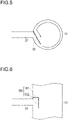
Figure 8] Figure 8 is a diagram showing a gas-liquid separator according to amodification 3, the diagram corresponding toFigure 2 . - [
Figure 9] Figure 9 is a schematic bottom view showing the gas-liquid separator according to themodification 3. - [
Figure 10] Figure 10 is a diagram showing a gas-liquid separator according to a modification 4, the diagram corresponding toFigure 2 . - [
Figure 11] Figure 11 is a graph showing a relationship between a flow velocity of a gas-liquid mixture and a separation efficiency. - An embodiment of the present invention will be described with reference to
Figure 1 to Figure 4 . In the description of the drawings, identical elements are given the same reference symbols, and the repeated description will be omitted. The dimensional ratios in the drawings are exaggerated for convenience of description, and may be different from the actual ratios. -
Figure 1 is a schematic transparent view showing a gas-liquid separator 1 according to an embodiment of the present invention.Figure 2 is a schematic vertical cross-sectional view showing the gas-liquid separator 1 according to this embodiment.Figure 3 is a diagram taken along a line A-A and seen from a direction indicated by arrows inFigure 2 , the diagram showing the gas-liquid separator 1 according to this embodiment.Figure 4 is a diagram for describing a configuration of astraightening plate 50 of the gas-liquid separator 1 according to this embodiment. - As shown in
Figure 1 , the gas-liquid separator 1 includes abody portion 10, anintroduction passage 20, anexhaust flow passage 30, an oildischarge flow passage 40, thestraightening plate 50, and apartition plate 60, thebody portion 10 having a cylindrical shape, a gas-liquid mixture being introduced through theintroduction passage 20, gas being exhausted through theexhaust flow passage 30, a refrigerating machine oil being discharged through the oildischarge flow passage 40, thestraightening plate 50 straightening the gas-liquid mixture, and thepartition plate 60 being provided at a position lower than theintroduction passage 20. The gas-liquid separator 1 is used for a gas compressor, is preferably used for a high-speed multicylinder refrigerating machine, and is more preferably used for a high-speed multicylinder refrigerating machine for ship. The gas-liquid separator 1 is used for returning oil accompanied by a compressed gas to a crankcase. - The
body portion 10 is formed into a cylindrical shape extending in an up-and-down direction. In this configuration, unlike a configuration disclosed inJP 5-296610 A partition plate 60, it is possible to narrow a swirl region R (seeFigure 2 ). Therefore, by increasing a swirl speed without dispersing the swirl flow, it is possible to improve a separation efficiency. Further, there is no conical funnel portion and hence, it is possible to form the gas-liquid separator 1 in a compact manner. - Although the
body portion 10 is formed of a steel pipe, for example, thebody portion 10 is not limited to the steel pipe. Although the size of thebody portion 10 is not particularly limited, it is preferable to set the size of thebody portion 10 to a size that allows gas and liquid to be suitably separated. Specifically, it is preferable to set the size of thebody portion 10 to a volume that allows a gas-liquid mixture to have a retention time of 0.6 seconds or more. - As shown in
Figure 3 , thestraightening plate 50 is disposed to extend in a chord length direction of a circular arc formed at a barrel of thebody portion 10 when viewed from above. One end of thestraightening plate 50 is connected to an inner wall of thebody portion 10, and the other end of thestraightening plate 50 has anend portion 50A. The straighteningplate 50 has a narrow width portion configured such that a distance between thestraightening plate 50 and the inner wall of thebody portion 10 gradually decreases. - As shown in
Figure 1 andFigure 2 , theintroduction passage 20 is provided in a state of communicating with thebody portion 10. Theintroduction passage 20 is provided as shown inFigure 3 . As shown inFigure 3 , theintroduction passage 20 is provided at a free angle with respect to a center of thebody portion 10 within a range of a circular arc formed with a length corresponding to 1/4 or less (90° or less shown inFigure 3 ) of a circumference of the barrel of thebody portion 10. - In a case where the
introduction passage 20 is attached to extend in a tangential direction with respect to thebody portion 10, for example, it is difficult to form a distorted hole in thebody portion 10 and to weld theintroduction passage 20 to thebody portion 10. In contrast, in the gas-liquid separator 1 according to this embodiment, theintroduction passage 20 is provided at the free angle and with a free offset amount with respect to the center of thebody portion 10 and hence, it is possible to easily weld theintroduction passage 20 to thebody portion 10. - As shown in
Figure 1 , theexhaust flow passage 30 is provided at an upper portion of thebody portion 10. Gas (gas) separated from a refrigerating machine oil (liquid) is exhausted through theexhaust flow passage 30. - As shown in
Figure 2 , an insertion portion of theexhaust flow passage 30 is configured to extend downward a short distance from anupper end portion 10A of thebody portion 10. - For example, assume a case where the
exhaust flow passage 30 has no insertion portion and is configured to extend upward from theupper end portion 10A, and theintroduction passage 20 and theexhaust flow passage 30 are disposed close to each other. In such a case, there is a possibility that, of a gas-liquid mixture that flows out in an upward direction from theend portion 50A of the straighteningplate 50, a portion of gas from which refrigerating machine oil is not sufficiently separated or a portion of refrigerating machine oil separated from the gas due to impingement separation is suctioned into theexhaust flow passage 30 and is discharged to the outside. - In contrast, the gas-
liquid separator 1 according to this embodiment is configured such that the insertion portion of theexhaust flow passage 30 extends downward in a short distance from theupper end portion 10A of thebody portion 10. Accordingly, of a gas-liquid mixture that flows out from theend portion 50A of the straighteningplate 50, an unseparated gas that is discharged to an outer peripheral region of the insertion portion in a space above the straighteningplate 50 or refrigerating machine oil separated from the gas is prevented from directly flowing into theexhaust flow passage 30 and hence, it is possible to suitably suppress a situation where the unseparated gas or the refrigerating machine oil is discharged to the outside. - As shown in
Figure 2 , it is preferable to stop the downward extension of the insertion portion of theexhaust flow passage 30 before the insertion portion reaches a position in the vicinity of a height of a first extendingportion 51 of the straighteningplate 50, which will be described later. Such a configuration can suppress a situation where the insertion portion of theexhaust flow passage 30 obstructs a generated swirl flow. Further, the insertion portion of theexhaust flow passage 30 can be easily assembled and constructed. - A lower portion of the
body portion 10 forms an oil storage portion. As shown inFigure 1 , the oildischarge flow passage 40 is provided at the lower portion of thebody portion 10. Refrigerating machine oil separated from gas is discharged through the oildischarge flow passage 40. Afloat valve 90 is disposed above the oildischarge flow passage 40. Thefloat valve 90 has a known configuration and hence, the detailed description of thefloat valve 90 will be omitted. - When the
float valve 90 is opened, refrigerating machine oil stored at the lower portion of thebody portion 10 is discharged through the oildischarge flow passage 40. After a lapse of a predetermined time period, thefloat valve 90 is closed and refrigerating machine oil is stored at the lower portion of thebody portion 10. - The straightening
plate 50 causes a gas-liquid mixture introduced through theintroduction passage 20 to be subject to impingement separation and changes a flow direction to a circumferential direction to straighten the flow. At the same time, the straighteningplate 50 increases a flow velocity of the gas-liquid mixture introduced through theintroduction passage 20. - As shown in
Figure 3 and Figure 4 , the straighteningplate 50 is fixed to an inner wall of an inflow portion formed in the inside of thebody portion 10. The straighteningplate 50 includes the first extendingportion 51, a second extendingportion 52, and a third extendingportion 53, the first extendingportion 51 extending inward in the substantially horizontal direction from an inner wall of thebody portion 10, the second extendingportion 52 being continuously formed with the first extendingportion 51 and extending in a downward direction, the third extendingportion 53 being continuously formed with the second extendingportion 52 and extending to the inner wall of thebody portion 10. For example, as shown inFigure 3 , the straighteningplate 50 is attached to extend along an X-Y line, that is, to extend in a chord length direction of a circular arc formed with a length corresponding to 1/4 or less (90° or less shown inFigure 3 ) of the circumference of the barrel of thebody portion 10. As shown inFigure 4 , the straighteningplate 50 is formed into a square U shape or a U shape when viewed in a front view. The straighteningplate 50 may be formed as an integral body by the first extendingportion 51, the second extendingportion 52, and the third extendingportion 53. - Although a method for fixing the first extending
portion 51 and the third extendingportion 53 to the inner wall of thebody portion 10 is not particularly limited, the first extendingportion 51 and the third extendingportion 53 are fixed to the inner wall of thebody portion 10 by welding, for example. The straighteningplate 50 may be integrally formed with the inner wall of thebody portion 10. As described above, the first extendingportion 51 does not vary the shape of anarrow width portion 54 with respect to thebody portion 10 and hence, it is possible to prevent breakage of the straighteningplate 50 or a reduction in service life of the straighteningplate 50. As shown inFigure 3 , the straighteningplate 50 extends to cover theintroduction passage 20 such that a gas-liquid mixture introduced through theintroduction passage 20 impinges on the straighteningplate 50. -
Figure 3 shows onestraightening plate 50 that has both a function of an impingement separation portion and a function of a flow direction straightening portion. The flow direction straightening portion may be formed by the straighteningplate 50 where the flow passage is narrowed toward thenarrow width portion 54. - The
narrow width portion 54 has a narrow flow passage toward an internal opening. Thenarrow width portion 54 generates a swirl flow in the inside of the barrel while ensuring a gas flow velocity suitable for centrifugation. Thenarrow width portion 54 also has a function of causing the gas-liquid mixture to diagonally impinge on a flow swirling in the barrel so as to prevent the gas-liquid mixture from opposing the flow swirling in the barrel. - As shown in
Figure 3 and Figure 4 , the first extendingportion 51 is formed to have a linear shape when viewed from above and when viewed in a front view. As shown inFigure 4 , the second extendingportion 52 is also formed to have a linear shape when viewed in a front view. - As described above, the first extending
portion 51 and the third extendingportion 53 are fixed to the inner wall of thebody portion 10 at positions above and below theintroduction passage 20 and hence, the first extendingportion 51 and the third extendingportion 53 act as baffle plates. Accordingly, it is possible to suitably suppress a situation where, of the gas-liquid mixture introduced through theintroduction passage 20, refrigerating machine oil is discharged through theexhaust flow passage 30. - As shown in
Figure 3 , the first extendingportion 51 and the third extendingportion 53 of the straighteningplate 50 have thenarrow width portion 54 configured such that a distance between the straighteningplate 50 and the inner wall of thebody portion 10 gradually decreases toward theend portion 50A when viewed from above, the gas-liquid mixture flowing out from theend portion 50A. That is, in the vicinity of thenarrow width portion 54, the straighteningplate 50 gradually approaches the inner wall of thebody portion 10 toward theend portion 50A of the first extendingportion 51 and the third extendingportion 53. As shown inFigure 3 , the straighteningplate 50 is formed to have a linear shape when viewed from above. With such a configuration, it is possible to increase a flow velocity of the gas-liquid mixture and hence, gas and liquid can be separated more suitably. Further, such a configuration does not require a guide plate and a guide path that are formed in the circumferential direction for approximately half of the circumference, the guide plate and the guide path being disclosed inJP 2004-52710 A - When the flow velocity of the gas-liquid mixture in the
introduction passage 20 is 4 m/s to 10 m/s, for example, the flow velocity of the gas-liquid mixture at theend portion 50A of the straighteningplate 50 is 6 m/s to 15 m/s. - As shown in
Figure 1 , thepartition plate 60 is provided at a position lower than theintroduction passage 20. Thepartition plate 60 is connected to the inner wall of thebody portion 10. Thepartition plate 60 has a small inner diameter, thus having an inner diameter of a so-called toroidal shape. Although the inner diameter of thepartition plate 60 is not particularly limited, the inner diameter of thepartition plate 60 is 0.4 to 0.6 times the inner diameter of thebody portion 10. - The
partition plate 60 is formed separately from thebody portion 10. Thepartition plate 60 is fixed to thebody portion 10 by welding, for example. - The
partition plate 60 is formed along an XY plane . That is, thepartition plate 60 is configured to be substantially horizontal without being inclined with respect to the gas-liquid separator 1. Thepartition plate 60 is provided along the horizontal direction as described above and hence, it is possible to easily manufacture the gas-liquid separator 1. - By providing the
partition plate 60 as described above, compared with a configuration where the partition plate is not provided, the swirl region R (seeFigure 2 ) extending along the up-and-down direction is narrowed and hence, it is possible to increase a swirl speed. Accordingly, it is possible to suitably separate gas and liquid. - As shown in
Figure 1 , thepartition plate 60 is disposed at a position sufficiently away from theexhaust flow passage 30. With such a configuration, oil adhering to the inner wall of thebody portion 10 due to the swirl flow of the gas-liquid mixture is gravitationally precipitated and temporarily stays on thepartition plate 60, and then descends to the oildischarge flow passage 40 from an opening portion of thepartition plate 60 without flowing out through theexhaust flow passage 30, the oildischarge flow passage 40 being disposed at a position lower than the opening portion of thepartition plate 60. - When a gas-liquid mixture is introduced into the gas-
liquid separator 1 having the above-mentioned configuration through theintroduction passage 20, the introduced gas-liquid mixture flows between the inner wall of thebody portion 10 and the straighteningplate 50 and flows out from theend portion 50A of the straighteningplate 50. The straighteningplate 50 has thenarrow width portion 54 and hence, the gas-liquid mixture flows out from theend portion 50A of the straighteningplate 50 at an increased flow velocity. The gas-liquid mixture that flows out from theend portion 50A of the straighteningplate 50 swirls along the inner wall of thebody portion 10, so that gas and liquid are centrifuged (seeFigure 3 ). In a region where swirling starts from theend portion 50A of the straighteningplate 50, there is no obstacles inhibiting the formation of the swirl flow, such as the inner cylinder, and no surface or protrusion impinging on oil droplets at right angles and thus causing scattering of the oil droplets. Accordingly, centrifugation can be performed by effectively using the inside of the barrel and hence, a high efficiency is achieved. - In a case where oil droplets of refrigerating machine oil have a small size, the refrigerating machine oil is not easily centrifuged. Therefore, when the gas-liquid mixture swirls along the inner wall of the
body portion 10, oil droplets are collected to form large oil droplets. With such a configuration, it is possible to cause the oil droplets to be gravitationally precipitated along the inner wall of thebody portion 10. - As described above, the gas-
liquid separator 1 according to this embodiment is the gas-liquid separator 1 that separates gas and liquid from a gas-liquid mixture. The gas-liquid separator 1 includes thebody portion 10, theintroduction passage 20, the straighteningplate 50, and theexhaust flow passage 30, thebody portion 10 having a cylindrical shape, theintroduction passage 20 being provided in a state of communicating with thebody portion 10, the gas-liquid mixture being introduced through theintroduction passage 20, the straighteningplate 50 being attached to thebody portion 10 and straightening the gas-liquid mixture to increase a flow velocity, and theexhaust flow passage 30 being provided for gas from which liquid is separated. The straighteningplate 50 is attached to extend in the chord length direction of the circular arc formed with the length corresponding to 1/4 or less (90° or less as shown inFigure 3 ) of the circumference of the barrel of thebody portion 10. Theintroduction passage 20 is connected at a free angle and a free offset amount within a range of the circular arc. The straighteningplate 50 has thenarrow width portion 54 configured such that a distance between the straighteningplate 50 and the inner wall of thebody portion 10 gradually decreases toward theend portion 50A from which the gas-liquid mixture flows out. In the gas-liquid separator 1 having such a configuration, the straighteningplate 50 has thenarrow width portion 54 configured such that the distance between the straighteningplate 50 and the inner wall of thebody portion 10 gradually decreases toward theend portion 50A from which the gas-liquid mixture flows out. Accordingly, it is possible to suitably separate gas and liquid by increasing the flow velocity of the gas-liquid mixture. - The straightening
plate 50 is formed to have a linear shape when viewed from above. For the gas-liquid separator 1 having such a configuration, it is possible to easily manufacture the straighteningplate 50. - When viewed in a front view, the straightening
plate 50 is fixed to the inner wall of thebody portion 10 at a position higher than theintroduction passage 20. In the gas-liquid separator 1 having such a configuration, it is possible to suitably suppress a situation where, of a gas-liquid mixture that flows out from theend portion 50A of the straighteningplate 50, refrigerating machine oil separated from gas is discharged through theexhaust flow passage 30. - The gas-
liquid separator 1 further includes thepartition plate 60 provided at a position lower than theintroduction passage 20 and having the inner diameter of a toroidal shape which is smaller than the inner diameter of thebody portion 10. In the gas-liquid separator 1 having such a configuration, it is unnecessary to use an auxiliary swirling mechanism, such as an inner cylinder, in the inside of thebody portion 10 and it is possible to sufficiently make use of the swirl region R extending along the up-and-down direction. Accordingly, the swirl region R is narrowed and a swirl speed can be increased and hence, it is possible to separate gas and liquid more suitably. - The
partition plate 60 is provided along the horizontal direction. In the gas-liquid separator 1 having such a configuration, it is possible to easily form thepartition plate 60. Gas fluid from which oil is separated rises at the center of the swirl flow from thepartition plate 60 toward theexhaust flow passage 30. The gas-liquid separator 1 having such a configuration does not require the tapered portion of the barrel which is provided at the lower portion of a conventional barrel, thus contributing to achieving a compact configuration. - The present invention is not limited to the above-mentioned embodiment, and various modifications are conceivable without departing from Claims.
- For example, in the above-mentioned embodiment, as shown in
Figure 3 and Figure 4 , the straighteningplate 50 includes the first extendingportion 51, the second extendingportion 52, and the third extendingportion 53 and is formed into a square U shape, the first extendingportion 51 extending substantially horizontally inward from the inner wall of thebody portion 10, the second extendingportion 52 being formed continuously with the first extendingportion 51 and extending in the downward direction, the third extendingportion 53 being formed continuously with the second extendingportion 52 and extending to the inner wall of thebody portion 10. However, as shown inFigure 6 , a straighteningplate 150 may be formed into an L shape including a first extendingportion 151 and a second extendingportion 152, the first extendingportion 151 extending substantially horizontally inward from the inner wall of the body portion, the second extendingportion 152 being formed continuously with the first extendingportion 151 and extending in the downward direction. - In the above-mentioned embodiment, the
partition plate 60 is provided along the horizontal direction. However, as shown inFigure 7 , apartition plate 160 may be configured to be inclined inward in the radial direction and in the downward direction. With such a configuration, it is possible to cause refrigerating machine oil on thepartition plate 160 to descend downward along an inclined surface and hence, it is possible to suitably suppress a situation where the refrigerating machine oil is stored on thepartition plate 160. - In the above-mentioned embodiment, the straightening
plate 50 is formed to have a linear shape when viewed from above. However, the configuration of the straightening plate is not limited to the configuration that has the narrow width portion configured such that the distance between the straightening plate and the inner wall of the body portion gradually decreases toward the end portion from which a gas-liquid mixture flows out. The straighteningplate 50 may be formed to have a curved shape, for example. - In the above-mentioned embodiment, the gas-
liquid separator 1 includes thepartition plate 60 having a toroidal shape. However, it is not always necessary for the gas-liquid separator 1 to include the partition plate having a toroidal shape. - In the above-mentioned embodiment, the gas-
liquid separator 1 includes thepartition plate 60 having a toroidal shape. However, as shown inFigure 8 and Figure 9 , a gas-liquid separator 2 may include apartition plate 260 that partitions thebody portion 10 into an upper portion and a lower portion in place of thepartition plate 60 having a toroidal shape. As shown inFigure 8 and Figure 9 , thepartition plate 260 has a throughhole 261 at an end portion, the throughhole 261 penetrating through thepartition plate 260 in the up-and-down direction. Although a size of the throughhole 261 is not particularly limited, when the inner diameter of thebody portion 10 is 150 to 160 mm, the size of the throughhole 261 is 15 mm × 15 mm, for example. - By providing the
partition plate 260 having the throughhole 261 at the end portion as described above, an amount of the gas-liquid mixture flowing to a space below thepartition plate 260 is reduced and hence, it is possible to reduce violent movement of thefloat valve 90 and movement of an oil surface. - As shown in
Figure 10 , in a gas-liquid separator 3, ademister 360 may be attached to thepartition plate 60. A method for attaching thedemister 360 to thepartition plate 60 is not particularly limited. Although thedemister 360 is not particularly limited, a demister made of SUS304 and having a wire diameter of 0.12 mm and a density of 360kg/m3 may be used for thedemister 360. InFigure 10 , thedemister 360 is attached to a lower side of thepartition plate 60. However, thedemister 360 may be attached to an upper side of thepartition plate 60, or may be attached in a state of being sandwiched between thepartition plates 60. - By attaching the
demister 360 to thepartition plate 60 as described above, thedemister 360 can suitably attenuate a swirl flow of a gas-liquid mixture and hence, it is possible to reduce violent movement of thefloat valve 90 and movement of an oil surface. - Next, performance characteristics of the gas-
liquid separator 1 will be described. First, for a gas-liquid mixture being a separation target, in a case where volume concentration of oil in a gas-liquid mixture that flows into thebody portion 10 is several percent, a large amount of oil is contained and a swirling force attenuates and hence, it is preferable to use thepartition plate 60 shown inFigure 1 andFigure 2 . In contrast, in a case where volume concentration of oil in a gas-liquid mixture that flows into thebody portion 10 is several parts per million, a small amount of oil is contained and a swirling force does not attenuate and hence, a swirl flow generated in thebody portion 10 is stronger. Accordingly, it is preferable to suppress violent movement of thefloat valve 90 and movement of an oil surface by reducing the size of the opening of the partition plate. In a case where it is difficult to determine the size of the opening of the partition plate with respect to volume concentration of oil that flows into thebody portion 10, it is preferable to reduce violent movement of thefloat valve 90 and movement of an oil surface by installing thedemister 360 on thepartition plate 60 having a large opening to provide a resistance. The above-mentioned advantageous effects can also be obtained even with the configuration of the above-mentionedpartition plate 260. -
Figure 11 shows the results obtained by measuring a separation efficiency and a pressure loss when a flow velocity of a gas-liquid mixture introduced into the gas-liquid separator 1 having the above-mentioned configuration through theintroduction passage 20 is changed within a range of 5 to 20 m/s. - In
Figure 11 , the horizontal axis shows the flow velocity of the gas-liquid mixture, black circles on the vertical axis show the separation efficiency, and white circles on the vertical axis show the pressure loss. As shown inFigure 11 , when the flow velocity of the gas-liquid mixture is changed to 5 m/s, 10 m/s, 15 m/s, and 20 m/s, a separation efficiency of 97% or more can be ensured at every flow velocity. Although the pressure loss increases with an increase in flow velocity of the gas-liquid mixture, it is found that a maximum pressure loss is 5kPa, which is not an especially high numerical value. - For the characteristic of the gas-
liquid separator 1, it is found that a high separation efficiency can be maintained even when a blowing velocity of a swirl flow is changed within a range of 5 m/sec to 20 m/sec. A pressure loss can be changed according to an allowable pressure loss of equipment in which the gas-liquid separator 1 is installed and hence, the degree of freedom in selection is increased. - As described above, in the method for separating refrigerating machine oil in gas with the gas-
liquid separator 1 according to this embodiment, first, gas that flows into thebody portion 10 through theintroduction passage 20 is subject to impingement separation at the straighteningplate 50 and, then, a gas-liquid mixture that flows out from theend portion 50A of the straighteningplate 50 swirls along the inner wall of thebody portion 10, so that gas and liquid are centrifuged. There is no obstacles inhibiting the formation of a swirl flow in a region where swirling starts and hence, it is possible to perform centrifugation and gravitational sedimentation by effectively using the inside of the barrel. Accordingly, it is possible to effectively make use of the space in the barrel and hence, oil is efficiently separated. Further, violent movement of an oil surface of refrigerating machine oil temporarily stored at the lower portion of thebody portion 10 and reaccompanying of oil due to the swirl flow are prevented by providing thepartition plate - Further, it is possible to omit the funnel portion provided at the lower portion and hence, it is possible to achieve a reduction in size and a compact structure. Accordingly, the gas-
liquid separator 1 can be used as an oil separator of a gas compressor, can be suitably used for a high-speed multicylinder refrigerating machine, and can be more suitably used for a high-speed multicylinder refrigerating machine for ship having a restriction on a mounting space. -
- 1
- gas-liquid separator
- 10
- body portion
- 10A
- upper end portion
- 20
- introduction passage
- 30
- exhaust flow passage
- 40
- oil discharge flow passage
- 50, 150
- straightening plate
- 50A
- end portion
- 51
- first extending portion
- 52
- second extending portion
- 53
- third extending portion
- 54
- narrow width portion
- 60, 160, 260
- partition plate
- 90
- float valve
- 360
- demister
Claims (11)
- A gas-liquid separator that separates gas and liquid from a gas-liquid mixture, the gas-liquid separator comprising:a body portion having a cylindrical shape;an introduction passage provided in a state of communicating with the body portion, the gas-liquid mixture being introduced through the introduction passage;a straightening plate attached to the body portion to extend in a chord length direction of a circular arc formed by a barrel of the body portion, the straightening plate being configured to straighten the gas-liquid mixture; andan exhaust flow passage provided for gas from which liquid is separated, whereinthe straightening plate has a narrow width portion configured such that a distance between the straightening plate and an inner wall of the body portion gradually decreases toward an end portion from which the gas-liquid mixture flows out, anda swirl portion in the body portion is formed by the body portion extending in an up-and-down direction and a partition plate.
- The gas-liquid separator according to claim 1, wherein an insertion portion of the exhaust flow passage is inserted into the body portion, and the insertion portion extends by an extension length that allows the insertion portion to reach a position of a height of an upper end of an extending portion of the straightening plate, the extending portion extending in a horizontal direction.
- The gas-liquid separator according to claim 1 or 2, wherein the straightening plate is disposed to extend in the chord length direction of the circular arc formed by the barrel of the body portion when viewed from above, one end of the straightening plate is connected to the inner wall of the body portion, and the other end of the straightening plate has a narrow width portion.
- The gas-liquid separator according to any one of claims 1 to 3, wherein the straightening plate is attached to extend in the chord length direction of the circular arc having a length corresponding to 1/4 or less of a circumference of the body portion.
- The gas-liquid separator according to claim 4, wherein the introduction passage is connected at a free angle and with a free offset amount within a range of the circular arc.
- The gas-liquid separator according to any one of claims 1 to 5, wherein a fluid is blown out from a distal end portion of the straightening plate, the distal end portion has a narrow width portion, and the narrow width portion is selected such that a blowing velocity of a swirl flow falls within a range of 5 m/sec to 20 m/sec.
- The gas-liquid separator according to any one of claims 1 to 6, wherein the straightening plate has a square U shape when viewed in a front view, and the straightening plate is fixed to the inner wall of the body portion at least at a position higher than the introduction passage.
- The gas-liquid separator according to any one of claims 1 to 7, wherein the partition plate is provided at a position lower than the introduction passage, and has an inner diameter smaller than an inner diameter of the body portion.
- The gas-liquid separator according to any one of claims 1 to 8, wherein the partition plate is provided along the horizontal direction.
- The gas-liquid separator according to any one of claims 1 to 9, further comprising a demister attached to the partition plate.
- The gas-liquid separator according to any one of claims 1 to 10, further comprising the partition plate provided at a position lower than the introduction passage, and configured to partition the body portion into an upper portion and a lower portion, wherein a through hole is formed at an end portion of the partition plate, the through hole penetrating through the partition plate in the up-and-down direction.
Priority Applications (1)
| Application Number | Priority Date | Filing Date | Title |
|---|---|---|---|
| RS20240942A RS65872B1 (en) | 2020-02-25 | 2020-12-21 | Gas-liquid separator |
Applications Claiming Priority (3)
| Application Number | Priority Date | Filing Date | Title |
|---|---|---|---|
| PCT/JP2020/007487 WO2021171369A1 (en) | 2020-02-25 | 2020-02-25 | Gas-liquid separator |
| PCT/JP2020/034459 WO2021171662A1 (en) | 2020-02-25 | 2020-09-11 | Gas-liquid separator |
| PCT/JP2020/047667 WO2021171755A1 (en) | 2020-02-25 | 2020-12-21 | Gas-liquid separator |
Publications (4)
| Publication Number | Publication Date |
|---|---|
| EP4112153A1 true EP4112153A1 (en) | 2023-01-04 |
| EP4112153A4 EP4112153A4 (en) | 2023-08-09 |
| EP4112153B1 EP4112153B1 (en) | 2024-08-14 |
| EP4112153C0 EP4112153C0 (en) | 2024-08-14 |
Family
ID=77489919
Family Applications (1)
| Application Number | Title | Priority Date | Filing Date |
|---|---|---|---|
| EP20920780.2A Active EP4112153B1 (en) | 2020-02-25 | 2020-12-21 | Gas-liquid separator |
Country Status (7)
| Country | Link |
|---|---|
| US (1) | US20240335843A1 (en) |
| EP (1) | EP4112153B1 (en) |
| JP (1) | JP7274596B2 (en) |
| HU (1) | HUE068009T2 (en) |
| RS (1) | RS65872B1 (en) |
| TW (1) | TWI758099B (en) |
| WO (1) | WO2021171755A1 (en) |
Families Citing this family (2)
| Publication number | Priority date | Publication date | Assignee | Title |
|---|---|---|---|---|
| CN115059601A (en) * | 2022-06-16 | 2022-09-16 | 西安交通大学 | Oil remover of gas storage gas injection compressor and working method thereof |
| JP2024130636A (en) * | 2023-03-15 | 2024-09-30 | 株式会社前川製作所 | Oil Separator |
Family Cites Families (11)
| Publication number | Priority date | Publication date | Assignee | Title |
|---|---|---|---|---|
| JPS5676054U (en) * | 1979-11-19 | 1981-06-20 | ||
| JP3180420B2 (en) * | 1992-03-30 | 2001-06-25 | 三菱マテリアル株式会社 | Powder classifier |
| JPH05296610A (en) | 1992-04-13 | 1993-11-09 | Daikin Ind Ltd | Centrifugal oil separator |
| TW439533U (en) * | 1998-10-15 | 2001-06-07 | Chen Jian Cheng | Liquid/gas separating device |
| JP2001246216A (en) | 1999-12-28 | 2001-09-11 | Denso Corp | Gas-liquid separation device |
| JP4167457B2 (en) | 2002-07-23 | 2008-10-15 | 北越工業株式会社 | Oil-cooled compressor receiver tank |
| EP2169332A3 (en) * | 2008-09-29 | 2014-12-03 | Sanyo Electric Co., Ltd. | Oil separator for separating refrigerant and oil |
| JP2013044456A (en) * | 2011-08-23 | 2013-03-04 | Hitachi Appliances Inc | Oil separator and refrigerating cycle apparatus |
| JP2014105582A (en) * | 2012-11-22 | 2014-06-09 | Aisin Seiki Co Ltd | Oil separator |
| JP6850238B2 (en) * | 2017-10-18 | 2021-03-31 | 株式会社神戸製鋼所 | Gas-liquid separator and oil-cooled compressor |
| CN211706363U (en) * | 2019-12-05 | 2020-10-20 | 中国石油大学(北京) | Gas-liquid separation apparatus |
-
2020
- 2020-12-21 HU HUE20920780A patent/HUE068009T2/en unknown
- 2020-12-21 WO PCT/JP2020/047667 patent/WO2021171755A1/en not_active Ceased
- 2020-12-21 RS RS20240942A patent/RS65872B1/en unknown
- 2020-12-21 EP EP20920780.2A patent/EP4112153B1/en active Active
- 2020-12-21 JP JP2021551907A patent/JP7274596B2/en active Active
- 2020-12-21 US US17/801,335 patent/US20240335843A1/en active Pending
-
2021
- 2021-02-19 TW TW110105831A patent/TWI758099B/en active
Also Published As
| Publication number | Publication date |
|---|---|
| EP4112153A4 (en) | 2023-08-09 |
| TW202131984A (en) | 2021-09-01 |
| EP4112153B1 (en) | 2024-08-14 |
| TWI758099B (en) | 2022-03-11 |
| US20240335843A1 (en) | 2024-10-10 |
| WO2021171755A1 (en) | 2021-09-02 |
| HUE068009T2 (en) | 2024-12-28 |
| EP4112153C0 (en) | 2024-08-14 |
| RS65872B1 (en) | 2024-09-30 |
| JP7274596B2 (en) | 2023-05-16 |
| JPWO2021171755A1 (en) | 2021-09-02 |
Similar Documents
| Publication | Publication Date | Title |
|---|---|---|
| US7871461B2 (en) | Bubble separator | |
| US6709476B2 (en) | Centrifugal air-oil separator | |
| US6475256B2 (en) | Cyclone type gas-liquid separator | |
| US7967901B2 (en) | Lubricating liquid separator | |
| EP4112153B1 (en) | Gas-liquid separator | |
| US9803900B2 (en) | Screw compressor and chiller unit provided with same | |
| JP2830618B2 (en) | Centrifugal oil separator | |
| CN107192182B (en) | Oil separator, compressor and air conditioner | |
| EP1839721A1 (en) | Gas-liquid separator | |
| KR20020070965A (en) | Oil separator and outdoor unit with the oil separator | |
| US20230311041A1 (en) | Gas-liquid separator | |
| CN113557073B (en) | Gas-liquid separator | |
| EP1541943B1 (en) | Gas liquid separator | |
| JP3593594B2 (en) | Gas-liquid separator | |
| CN102230704A (en) | Centrifugal oil and gas separator | |
| JPH10311627A (en) | Oil separator | |
| JP2001121036A (en) | Centrifugal separator | |
| JP4063179B2 (en) | Oil separator | |
| JPH1019422A (en) | Oil separator | |
| WO2019077945A1 (en) | Gas-liquid separator and oil-cooled compressor | |
| JPH10185367A (en) | Oil separator | |
| BR112022016296B1 (en) | GAS-LIQUID SEPARATOR | |
| JPH0610859A (en) | Horizontal scroll compressor | |
| JPH05196325A (en) | accumulator | |
| JP2006305525A (en) | Gas-liquid separator |
Legal Events
| Date | Code | Title | Description |
|---|---|---|---|
| STAA | Information on the status of an ep patent application or granted ep patent |
Free format text: STATUS: THE INTERNATIONAL PUBLICATION HAS BEEN MADE |
|
| PUAI | Public reference made under article 153(3) epc to a published international application that has entered the european phase |
Free format text: ORIGINAL CODE: 0009012 |
|
| STAA | Information on the status of an ep patent application or granted ep patent |
Free format text: STATUS: REQUEST FOR EXAMINATION WAS MADE |
|
| 17P | Request for examination filed |
Effective date: 20220824 |
|
| AK | Designated contracting states |
Kind code of ref document: A1 Designated state(s): AL AT BE BG CH CY CZ DE DK EE ES FI FR GB GR HR HU IE IS IT LI LT LU LV MC MK MT NL NO PL PT RO RS SE SI SK SM TR |
|
| DAV | Request for validation of the european patent (deleted) | ||
| DAX | Request for extension of the european patent (deleted) | ||
| A4 | Supplementary search report drawn up and despatched |
Effective date: 20230711 |
|
| RIC1 | Information provided on ipc code assigned before grant |
Ipc: B04C 5/15 20060101ALI20230705BHEP Ipc: B04C 5/103 20060101ALI20230705BHEP Ipc: B01D 45/08 20060101ALI20230705BHEP Ipc: B01D 45/16 20060101ALI20230705BHEP Ipc: F04C 29/02 20060101ALI20230705BHEP Ipc: F25B 43/02 20060101ALI20230705BHEP Ipc: F04B 39/04 20060101ALI20230705BHEP Ipc: B04C 5/04 20060101ALI20230705BHEP Ipc: B01D 45/12 20060101AFI20230705BHEP |
|
| GRAP | Despatch of communication of intention to grant a patent |
Free format text: ORIGINAL CODE: EPIDOSNIGR1 |
|
| STAA | Information on the status of an ep patent application or granted ep patent |
Free format text: STATUS: GRANT OF PATENT IS INTENDED |
|
| GRAJ | Information related to disapproval of communication of intention to grant by the applicant or resumption of examination proceedings by the epo deleted |
Free format text: ORIGINAL CODE: EPIDOSDIGR1 |
|
| STAA | Information on the status of an ep patent application or granted ep patent |
Free format text: STATUS: REQUEST FOR EXAMINATION WAS MADE |
|
| GRAP | Despatch of communication of intention to grant a patent |
Free format text: ORIGINAL CODE: EPIDOSNIGR1 |
|
| STAA | Information on the status of an ep patent application or granted ep patent |
Free format text: STATUS: GRANT OF PATENT IS INTENDED |
|
| INTG | Intention to grant announced |
Effective date: 20240212 |
|
| INTG | Intention to grant announced |
Effective date: 20240307 |
|
| GRAS | Grant fee paid |
Free format text: ORIGINAL CODE: EPIDOSNIGR3 |
|
| GRAA | (expected) grant |
Free format text: ORIGINAL CODE: 0009210 |
|
| STAA | Information on the status of an ep patent application or granted ep patent |
Free format text: STATUS: THE PATENT HAS BEEN GRANTED |
|
| AK | Designated contracting states |
Kind code of ref document: B1 Designated state(s): AL AT BE BG CH CY CZ DE DK EE ES FI FR GB GR HR HU IE IS IT LI LT LU LV MC MK MT NL NO PL PT RO RS SE SI SK SM TR |
|
| REG | Reference to a national code |
Ref country code: GB Ref legal event code: FG4D |
|
| REG | Reference to a national code |
Ref country code: CH Ref legal event code: EP |
|
| REG | Reference to a national code |
Ref country code: DE Ref legal event code: R096 Ref document number: 602020035988 Country of ref document: DE |
|
| REG | Reference to a national code |
Ref country code: IE Ref legal event code: FG4D |
|
| U01 | Request for unitary effect filed |
Effective date: 20240904 |
|
| U07 | Unitary effect registered |
Designated state(s): AT BE BG DE DK EE FI FR IT LT LU LV MT NL PT RO SE SI Effective date: 20240923 |
|
| U20 | Renewal fee for the european patent with unitary effect paid |
Year of fee payment: 5 Effective date: 20241107 |
|
| REG | Reference to a national code |
Ref country code: HU Ref legal event code: AG4A Ref document number: E068009 Country of ref document: HU |
|
| PG25 | Lapsed in a contracting state [announced via postgrant information from national office to epo] |
Ref country code: NO Free format text: LAPSE BECAUSE OF FAILURE TO SUBMIT A TRANSLATION OF THE DESCRIPTION OR TO PAY THE FEE WITHIN THE PRESCRIBED TIME-LIMIT Effective date: 20241114 |
|
| PG25 | Lapsed in a contracting state [announced via postgrant information from national office to epo] |
Ref country code: PL Free format text: LAPSE BECAUSE OF FAILURE TO SUBMIT A TRANSLATION OF THE DESCRIPTION OR TO PAY THE FEE WITHIN THE PRESCRIBED TIME-LIMIT Effective date: 20240814 Ref country code: GR Free format text: LAPSE BECAUSE OF FAILURE TO SUBMIT A TRANSLATION OF THE DESCRIPTION OR TO PAY THE FEE WITHIN THE PRESCRIBED TIME-LIMIT Effective date: 20241115 |
|
| PG25 | Lapsed in a contracting state [announced via postgrant information from national office to epo] |
Ref country code: IS Free format text: LAPSE BECAUSE OF FAILURE TO SUBMIT A TRANSLATION OF THE DESCRIPTION OR TO PAY THE FEE WITHIN THE PRESCRIBED TIME-LIMIT Effective date: 20241214 |
|
| PG25 | Lapsed in a contracting state [announced via postgrant information from national office to epo] |
Ref country code: HR Free format text: LAPSE BECAUSE OF FAILURE TO SUBMIT A TRANSLATION OF THE DESCRIPTION OR TO PAY THE FEE WITHIN THE PRESCRIBED TIME-LIMIT Effective date: 20240814 |
|
| PG25 | Lapsed in a contracting state [announced via postgrant information from national office to epo] |
Ref country code: ES Free format text: LAPSE BECAUSE OF FAILURE TO SUBMIT A TRANSLATION OF THE DESCRIPTION OR TO PAY THE FEE WITHIN THE PRESCRIBED TIME-LIMIT Effective date: 20240814 |
|
| PG25 | Lapsed in a contracting state [announced via postgrant information from national office to epo] |
Ref country code: PL Free format text: LAPSE BECAUSE OF FAILURE TO SUBMIT A TRANSLATION OF THE DESCRIPTION OR TO PAY THE FEE WITHIN THE PRESCRIBED TIME-LIMIT Effective date: 20240814 Ref country code: NO Free format text: LAPSE BECAUSE OF FAILURE TO SUBMIT A TRANSLATION OF THE DESCRIPTION OR TO PAY THE FEE WITHIN THE PRESCRIBED TIME-LIMIT Effective date: 20241114 Ref country code: IS Free format text: LAPSE BECAUSE OF FAILURE TO SUBMIT A TRANSLATION OF THE DESCRIPTION OR TO PAY THE FEE WITHIN THE PRESCRIBED TIME-LIMIT Effective date: 20241214 Ref country code: HR Free format text: LAPSE BECAUSE OF FAILURE TO SUBMIT A TRANSLATION OF THE DESCRIPTION OR TO PAY THE FEE WITHIN THE PRESCRIBED TIME-LIMIT Effective date: 20240814 Ref country code: GR Free format text: LAPSE BECAUSE OF FAILURE TO SUBMIT A TRANSLATION OF THE DESCRIPTION OR TO PAY THE FEE WITHIN THE PRESCRIBED TIME-LIMIT Effective date: 20241115 Ref country code: ES Free format text: LAPSE BECAUSE OF FAILURE TO SUBMIT A TRANSLATION OF THE DESCRIPTION OR TO PAY THE FEE WITHIN THE PRESCRIBED TIME-LIMIT Effective date: 20240814 |
|
| PG25 | Lapsed in a contracting state [announced via postgrant information from national office to epo] |
Ref country code: SM Free format text: LAPSE BECAUSE OF FAILURE TO SUBMIT A TRANSLATION OF THE DESCRIPTION OR TO PAY THE FEE WITHIN THE PRESCRIBED TIME-LIMIT Effective date: 20240814 |
|
| PG25 | Lapsed in a contracting state [announced via postgrant information from national office to epo] |
Ref country code: SK Free format text: LAPSE BECAUSE OF FAILURE TO SUBMIT A TRANSLATION OF THE DESCRIPTION OR TO PAY THE FEE WITHIN THE PRESCRIBED TIME-LIMIT Effective date: 20240814 |
|
| PLBE | No opposition filed within time limit |
Free format text: ORIGINAL CODE: 0009261 |
|
| STAA | Information on the status of an ep patent application or granted ep patent |
Free format text: STATUS: NO OPPOSITION FILED WITHIN TIME LIMIT |
|
| PG25 | Lapsed in a contracting state [announced via postgrant information from national office to epo] |
Ref country code: MC Free format text: LAPSE BECAUSE OF FAILURE TO SUBMIT A TRANSLATION OF THE DESCRIPTION OR TO PAY THE FEE WITHIN THE PRESCRIBED TIME-LIMIT Effective date: 20240814 |
|
| 26N | No opposition filed |
Effective date: 20250515 |
|
| REG | Reference to a national code |
Ref country code: CH Ref legal event code: PL |
|
| GBPC | Gb: european patent ceased through non-payment of renewal fee |
Effective date: 20241221 |
|
| PG25 | Lapsed in a contracting state [announced via postgrant information from national office to epo] |
Ref country code: GB Free format text: LAPSE BECAUSE OF NON-PAYMENT OF DUE FEES Effective date: 20241221 |
|
| PG25 | Lapsed in a contracting state [announced via postgrant information from national office to epo] |
Ref country code: CH Free format text: LAPSE BECAUSE OF NON-PAYMENT OF DUE FEES Effective date: 20241231 |
|
| PG25 | Lapsed in a contracting state [announced via postgrant information from national office to epo] |
Ref country code: IE Free format text: LAPSE BECAUSE OF NON-PAYMENT OF DUE FEES Effective date: 20241221 |
|
| U20 | Renewal fee for the european patent with unitary effect paid |
Year of fee payment: 6 Effective date: 20251110 |
|
| PGFP | Annual fee paid to national office [announced via postgrant information from national office to epo] |
Ref country code: HU Payment date: 20251127 Year of fee payment: 6 |
|
| PGFP | Annual fee paid to national office [announced via postgrant information from national office to epo] |
Ref country code: CZ Payment date: 20251208 Year of fee payment: 6 |
|
| PGFP | Annual fee paid to national office [announced via postgrant information from national office to epo] |
Ref country code: RS Payment date: 20251210 Year of fee payment: 6 |
|
| PG25 | Lapsed in a contracting state [announced via postgrant information from national office to epo] |
Ref country code: CY Free format text: LAPSE BECAUSE OF FAILURE TO SUBMIT A TRANSLATION OF THE DESCRIPTION OR TO PAY THE FEE WITHIN THE PRESCRIBED TIME-LIMIT Effective date: 20240814 |