EP4112102A1 - Lock adapter, syringe assembly, and prefilled syringe - Google Patents
Lock adapter, syringe assembly, and prefilled syringe Download PDFInfo
- Publication number
- EP4112102A1 EP4112102A1 EP21775747.5A EP21775747A EP4112102A1 EP 4112102 A1 EP4112102 A1 EP 4112102A1 EP 21775747 A EP21775747 A EP 21775747A EP 4112102 A1 EP4112102 A1 EP 4112102A1
- Authority
- EP
- European Patent Office
- Prior art keywords
- lock adapter
- tip end
- nozzle portion
- syringe
- rotation restricting
- Prior art date
- Legal status (The legal status is an assumption and is not a legal conclusion. Google has not performed a legal analysis and makes no representation as to the accuracy of the status listed.)
- Pending
Links
Images






Classifications
-
- A—HUMAN NECESSITIES
- A61—MEDICAL OR VETERINARY SCIENCE; HYGIENE
- A61M—DEVICES FOR INTRODUCING MEDIA INTO, OR ONTO, THE BODY; DEVICES FOR TRANSDUCING BODY MEDIA OR FOR TAKING MEDIA FROM THE BODY; DEVICES FOR PRODUCING OR ENDING SLEEP OR STUPOR
- A61M39/00—Tubes, tube connectors, tube couplings, valves, access sites or the like, specially adapted for medical use
- A61M39/10—Tube connectors; Tube couplings
-
- A—HUMAN NECESSITIES
- A61—MEDICAL OR VETERINARY SCIENCE; HYGIENE
- A61M—DEVICES FOR INTRODUCING MEDIA INTO, OR ONTO, THE BODY; DEVICES FOR TRANSDUCING BODY MEDIA OR FOR TAKING MEDIA FROM THE BODY; DEVICES FOR PRODUCING OR ENDING SLEEP OR STUPOR
- A61M5/00—Devices for bringing media into the body in a subcutaneous, intra-vascular or intramuscular way; Accessories therefor, e.g. filling or cleaning devices, arm-rests
- A61M5/178—Syringes
- A61M5/31—Details
- A61M5/32—Needles; Details of needles pertaining to their connection with syringe or hub; Accessories for bringing the needle into, or holding the needle on, the body; Devices for protection of needles
- A61M5/34—Constructions for connecting the needle, e.g. to syringe nozzle or needle hub
- A61M5/344—Constructions for connecting the needle, e.g. to syringe nozzle or needle hub using additional parts, e.g. clamping rings or collets
- A61M5/345—Adaptors positioned between needle hub and syringe nozzle
-
- A—HUMAN NECESSITIES
- A61—MEDICAL OR VETERINARY SCIENCE; HYGIENE
- A61M—DEVICES FOR INTRODUCING MEDIA INTO, OR ONTO, THE BODY; DEVICES FOR TRANSDUCING BODY MEDIA OR FOR TAKING MEDIA FROM THE BODY; DEVICES FOR PRODUCING OR ENDING SLEEP OR STUPOR
- A61M5/00—Devices for bringing media into the body in a subcutaneous, intra-vascular or intramuscular way; Accessories therefor, e.g. filling or cleaning devices, arm-rests
- A61M5/178—Syringes
- A61M5/28—Syringe ampoules or carpules, i.e. ampoules or carpules provided with a needle
-
- A—HUMAN NECESSITIES
- A61—MEDICAL OR VETERINARY SCIENCE; HYGIENE
- A61M—DEVICES FOR INTRODUCING MEDIA INTO, OR ONTO, THE BODY; DEVICES FOR TRANSDUCING BODY MEDIA OR FOR TAKING MEDIA FROM THE BODY; DEVICES FOR PRODUCING OR ENDING SLEEP OR STUPOR
- A61M5/00—Devices for bringing media into the body in a subcutaneous, intra-vascular or intramuscular way; Accessories therefor, e.g. filling or cleaning devices, arm-rests
- A61M5/178—Syringes
- A61M5/28—Syringe ampoules or carpules, i.e. ampoules or carpules provided with a needle
- A61M5/285—Syringe ampoules or carpules, i.e. ampoules or carpules provided with a needle with sealing means to be broken or opened
-
- A—HUMAN NECESSITIES
- A61—MEDICAL OR VETERINARY SCIENCE; HYGIENE
- A61M—DEVICES FOR INTRODUCING MEDIA INTO, OR ONTO, THE BODY; DEVICES FOR TRANSDUCING BODY MEDIA OR FOR TAKING MEDIA FROM THE BODY; DEVICES FOR PRODUCING OR ENDING SLEEP OR STUPOR
- A61M5/00—Devices for bringing media into the body in a subcutaneous, intra-vascular or intramuscular way; Accessories therefor, e.g. filling or cleaning devices, arm-rests
- A61M5/178—Syringes
- A61M5/31—Details
- A61M5/3129—Syringe barrels
-
- A—HUMAN NECESSITIES
- A61—MEDICAL OR VETERINARY SCIENCE; HYGIENE
- A61M—DEVICES FOR INTRODUCING MEDIA INTO, OR ONTO, THE BODY; DEVICES FOR TRANSDUCING BODY MEDIA OR FOR TAKING MEDIA FROM THE BODY; DEVICES FOR PRODUCING OR ENDING SLEEP OR STUPOR
- A61M5/00—Devices for bringing media into the body in a subcutaneous, intra-vascular or intramuscular way; Accessories therefor, e.g. filling or cleaning devices, arm-rests
- A61M5/178—Syringes
- A61M5/31—Details
- A61M5/3129—Syringe barrels
- A61M5/3134—Syringe barrels characterised by constructional features of the distal end, i.e. end closest to the tip of the needle cannula
-
- A—HUMAN NECESSITIES
- A61—MEDICAL OR VETERINARY SCIENCE; HYGIENE
- A61M—DEVICES FOR INTRODUCING MEDIA INTO, OR ONTO, THE BODY; DEVICES FOR TRANSDUCING BODY MEDIA OR FOR TAKING MEDIA FROM THE BODY; DEVICES FOR PRODUCING OR ENDING SLEEP OR STUPOR
- A61M5/00—Devices for bringing media into the body in a subcutaneous, intra-vascular or intramuscular way; Accessories therefor, e.g. filling or cleaning devices, arm-rests
- A61M5/178—Syringes
- A61M5/31—Details
- A61M5/32—Needles; Details of needles pertaining to their connection with syringe or hub; Accessories for bringing the needle into, or holding the needle on, the body; Devices for protection of needles
- A61M5/3286—Needle tip design, e.g. for improved penetration
-
- A—HUMAN NECESSITIES
- A61—MEDICAL OR VETERINARY SCIENCE; HYGIENE
- A61M—DEVICES FOR INTRODUCING MEDIA INTO, OR ONTO, THE BODY; DEVICES FOR TRANSDUCING BODY MEDIA OR FOR TAKING MEDIA FROM THE BODY; DEVICES FOR PRODUCING OR ENDING SLEEP OR STUPOR
- A61M5/00—Devices for bringing media into the body in a subcutaneous, intra-vascular or intramuscular way; Accessories therefor, e.g. filling or cleaning devices, arm-rests
- A61M5/178—Syringes
- A61M5/31—Details
- A61M5/32—Needles; Details of needles pertaining to their connection with syringe or hub; Accessories for bringing the needle into, or holding the needle on, the body; Devices for protection of needles
- A61M5/3293—Needles; Details of needles pertaining to their connection with syringe or hub; Accessories for bringing the needle into, or holding the needle on, the body; Devices for protection of needles characterised by features of the needle hub
-
- A—HUMAN NECESSITIES
- A61—MEDICAL OR VETERINARY SCIENCE; HYGIENE
- A61M—DEVICES FOR INTRODUCING MEDIA INTO, OR ONTO, THE BODY; DEVICES FOR TRANSDUCING BODY MEDIA OR FOR TAKING MEDIA FROM THE BODY; DEVICES FOR PRODUCING OR ENDING SLEEP OR STUPOR
- A61M5/00—Devices for bringing media into the body in a subcutaneous, intra-vascular or intramuscular way; Accessories therefor, e.g. filling or cleaning devices, arm-rests
- A61M5/178—Syringes
- A61M5/31—Details
- A61M2005/3103—Leak prevention means for distal end of syringes, i.e. syringe end for mounting a needle
- A61M2005/3104—Caps for syringes without needle
-
- A—HUMAN NECESSITIES
- A61—MEDICAL OR VETERINARY SCIENCE; HYGIENE
- A61M—DEVICES FOR INTRODUCING MEDIA INTO, OR ONTO, THE BODY; DEVICES FOR TRANSDUCING BODY MEDIA OR FOR TAKING MEDIA FROM THE BODY; DEVICES FOR PRODUCING OR ENDING SLEEP OR STUPOR
- A61M39/00—Tubes, tube connectors, tube couplings, valves, access sites or the like, specially adapted for medical use
- A61M39/10—Tube connectors; Tube couplings
- A61M2039/1077—Adapters, e.g. couplings adapting a connector to one or several other connectors
Definitions
- the present invention relates to a lock adapter, a syringe assembly, and a prefilled syringe for an injector.
- a lock adapter is attached to the periphery of a nozzle portion at the tip end of the syringe, and a cap covering the nozzle portion is screwed into a female screw of the lock adapter for sealing.
- JP 2008-35913 A discloses a prefilled syringe having a slidable lock adapter in which the lock adapter is configured slidable in the axial direction.
- a slide portion for allowing the lock adapter to slide in the axial direction is provided at a base portion of the nozzle portion.
- the slide portion is provided with six rotation restricting ribs extending in the axial direction to prevent rotation of the lock adapter, and an annular rib extending in the circumferential direction along a boundary between the slide portion and the base portion of a luer tip.
- the lock adapter is provided with six claw portions extending inward.
- the claw portions of the lock adapter are disposed between the rotation restricting ribs and configured to slide in the axial direction along the outer surface of the slide portion.
- the claw portions of the lock adapter are caught by the annular rib, so that the lock adapter is prevented from coming off from the slide portion while withstanding the tightening load of the cap.
- the claw portions of the lock adapter are fragile, and when the autoclave sterilization process is performed in a state where the cap is screwed thereon, the strength of the claw portions becomes insufficient due to application of heat. As a result, the claw portions might not be able to withstand the load acting from the cap, and thus are deformed.
- Variation may thus be increased in the position on the tip end side of the lock adapter after being subjected to the autoclave sterilization process, so that it may be difficult to keep the position within the desired dimensional tolerance.
- An object of one embodiment is to provide a lock adapter, a syringe assembly, and a prefilled syringe capable of suppressing variation in position on the tip end side of the lock adapter after being subjected to an autoclave sterilization process.
- a lock adapter attached to the periphery of a nozzle portion at the tip end of a prefilled syringe and configured slidable in the axial direction of the nozzle portion
- the lock adapter including: a cylindrical body portion formed in a cylindrical shape surrounding the periphery of the nozzle portion; and a claw portion protruding to the inner peripheral side from a base end portion of the cylindrical body portion, and configured to determine a tip end position of the lock adapter by being caught in an annular rib extending in the circumferential direction of the nozzle portion, in which the claw portion is formed in a circumferential shape when viewed from the axial direction and is integrally connected in the circumferential direction.
- a syringe assembly including: a syringe body having a lumen capable of accommodating a medicinal solution; a nozzle portion formed at the tip end of the syringe body; and a lock adapter attached to the outer periphery of the nozzle portion, in which the nozzle portion includes: a slide portion provided on the base end side and on which the lock adapter is slidable in the axial direction; a luer tip provided on the tip end side of the slide portion; and an annular rib extending and protruding in the circumferential direction along a boundary between the luer tip and the slide portion, the lock adapter includes: a cylindrical body portion formed in a cylindrical shape surrounding the periphery of the nozzle portion; and a claw portion protruding to the inner peripheral side from a base end portion of the cylindrical body portion, and configured to determine a tip end position of the lock adapter by being caught in the annular rib extending in the circumferential direction of the nozzle portion, and
- a prefilled syringe including: a syringe body having a lumen accommodating a medicinal solution; a gasket to be inserted from the base end side of the syringe body to seal the lumen; a nozzle portion formed at the tip end of the syringe body; a lock adapter attached to the outer periphery of the nozzle portion; and a cap to be screwed into the lock adapter to seal the nozzle portion, in which the nozzle portion includes: a slide portion provided on the base end side and on which the lock adapter is slidable in the axial direction; a luer tip provided on the tip end side of the slide portion; and an annular rib extending and protruding in the circumferential direction along a boundary between the luer tip and the slide portion, the lock adapter includes: a cylindrical body portion formed in a cylindrical shape surrounding the periphery of the nozzle portion; and a claw portion protruding to the inner peripheral side from a
- a lock adapter 22 a syringe assembly 50, and a prefilled syringe 10 will be described in detail with reference to the accompanying drawings.
- the side of a nozzle portion 18 of the prefilled syringe 10 is referred to as the tip end or the tip end side
- the side of a flange portion 16 of the prefilled syringe 10 is referred to as the base end or the base end side.
- an alternate long and short dash line A in the drawings represents an axis of the prefilled syringe 10
- the direction of the alternate long and short dash line A is referred to as the axial direction.
- the prefilled syringe 10 includes a syringe body 12 formed in a cylindrical shape, and a lumen 13 extending in the axial direction is formed inside the syringe body 12.
- a base end opening portion 14 through which the lumen 13 opens is provided on the base end side of the syringe body 12.
- a gasket 15 is inserted into the lumen 13 from the base end opening portion 14.
- the gasket 15 is configured slidable in the axial direction while liquid-tightly sealing the inside of the lumen 13, and a portion of the lumen 13 closer to the tip end side than the gasket 15 is a drug chamber that is liquid-tightly sealed by the gasket 15.
- the drug chamber of the lumen 13 sealed by the gasket 15 is filled with a medicinal solution or a liquid preparation such as injection water or physiological saline for dilution in advance.
- the prefilled syringe 10 may be provided to a user in a state where a plunger (not illustrated) is attached, and in such a case, a plunger (pusher) for pressing the gasket 15 may be attached to the gasket 15.
- a constituent material of the gasket 15 a rubber material having elasticity, an elastomer material, or the like can be used.
- the flange portion 16 is formed to protrude radially outward.
- a finger grip (not illustrated) can be attached to the flange portion 16.
- the finger grip may be attached to the flange portion 16 in advance.
- the flange portion 16 and the finger grip may be integrally formed.
- a neck portion 17 having a diameter smaller than that of the syringe body 12 is formed at the tip end of the syringe body 12. From the neck portion 17, the nozzle portion 18 is formed to protrude toward the tip end side. As illustrated in Fig. 2 , a flow path 18a is formed inside the nozzle portion 18. The flow path 18a has an opening at a tip end surface 18b of the nozzle portion 18. The base end side of the flow path 18a communicates with the lumen 13.
- the prefilled syringe 10 is configured to be capable of discharging a medicinal solution from the tip end surface 18b of the nozzle portion 18.
- a syringe barrel 20 including the syringe body 12, the flange portion 16, and the nozzle portion 18 is formed of a transparent resin material or glass, which enables the lumen 13 to be visually recognized. Furthermore, a scale for recognizing the liquid amount of the medicinal solution may be provided at the side portion of the syringe body 12.
- the lock adapter 22 and a cap 24 are attached to the nozzle portion 18.
- the lock adapter 22 is a cylindrical member attached to the outer peripheral portion of the nozzle portion 18.
- a female screw 25 is formed on an inner peripheral portion 22a of the lock adapter 22.
- the cap 24 illustrated in Fig. 1 is detachably screwed into the lock adapter 22.
- the cap 24 seals the opening portion of the flow path 18a of the nozzle portion 18 in a state of being screwed into the lock adapter 22.
- the tip end of the nozzle portion 18 is exposed, so that it is enabled to connect a connector of a connection tube, a needle module, or the like to the nozzle portion 18.
- the lock adapter 22 is attached to the outer peripheral portion of the nozzle portion 18.
- the lock adapter 22 is configured slidable in the axial direction within a range of a slide portion 33 provided in the nozzle portion 18.
- the lock adapter 22 includes a cylindrical body portion 23 formed in a substantially hexagonal cylindrical shape.
- a circular insertion hole 23a is formed inside the cylindrical body portion 23.
- a female screw 25 is formed on an inner peripheral portion 22a of the cylindrical body portion 23, the inner peripheral portion 22a facing the insertion hole 23a.
- a tip end surface 22b erected perpendicularly to the axial direction is formed on the tip end side of the cylindrical body portion 23.
- the tip end surface 22b is formed in a substantially hexagonal shape when viewed from the tip end side, and six lock protrusions 27 are formed in a portion corresponding to each corner portion of the hexagonal shape so as to protrude toward the tip end.
- Each lock protrusion 27 has the outer peripheral side formed in a quarter spherical shape. This lock protrusion 27 makes contact with an anti-loosening protrusion 40b (see Fig. 9 ) of the cap 24 to prevent loosening of the cap 24.
- a base end portion 28 having a base end surface 22c erected perpendicularly to the axial direction is formed on the base end side of the cylindrical body portion 23 of the lock adapter 22.
- a claw portion 30 is formed to protrude from the base end portion 28 toward the inside of the insertion hole 23a.
- the claw portion 30 is formed in a circular ring shape (circumferential shape) when viewed from the axial direction, and is integrally formed over the entire circumferential direction.
- An inner peripheral surface 30a (see Fig. 4 ) of the claw portion 30 is formed to have an inner diameter slightly larger than the outer diameter of the slide portion 33 in order to make the slide portion 33 slidable. Furthermore, rotation restricting portions 31 are formed at some parts of the claw portion 30 in the circumferential direction. Each of the rotation restricting portions 31 has a pair of rotation restricting protrusions 31a protruding inward from the claw portion 30. The rotation restricting protrusions 31a are formed so as to protrude inward from the inner peripheral surface 30a of the claw portion 30. The pair of rotation restricting protrusions 31a is separated from each other by the same width as that of a rotation restricting rib 36 (see Fig.
- the position (inner diameter) of the inner periphery of the slide groove 31b is substantially the same as the position (inner diameter) of the inner peripheral surface 30a of the claw portion 30.
- the rotation restricting protrusions 31a and the slide groove 31b are engaged with the rotation restricting rib 36 to prevent the rotation of the lock adapter 22 in the circumferential direction.
- the claw portion 30 makes contact with an annular rib 32 to be described later of the nozzle portion 18 to prevent the movement of the lock adapter 22 to the tip end side. That is, the tip end position of the lock adapter 22 is determined by the claw portion 30.
- the lock adapter 22 covers the periphery of a luer tip 34.
- the cap 24, the needle module, the connector, or the like can be connected to the female screw 25 on the inner peripheral portion 22a.
- the lock adapter 22 is moved to the base end side, the most portion of the luer tip 34 is exposed from the lock adapter 22.
- the position of the female screw 25 and the position of the tip end surface 22b of the lock adapter 22 in the tip end position of the lock adapter 22 are defined by a corresponding standard.
- ISO 80369-7 which is a standard related to small-diameter syringes
- the axial dimension c from the tip end surface 18b of the nozzle portion 18 to the tip end surface 22b of the lock adapter 22 is defined to fall within 2.100 to 2.573 mm.
- a resin material such as polypropylene, polyethylene, polycarbonate, polyester, or cyclic polyolefin can be used.
- a heat-resistant resin such as polypropylene or cyclic polyolefin is preferably used from the viewpoint of preventing deformation during heating in autoclave sterilization.
- the nozzle portion 18 to which the lock adapter 22 is attached is formed on the tip end side of the neck portion 17, which is a reduced diameter portion of the tip end of the syringe body 12.
- the nozzle portion 18 includes the slide portion 33 formed on the tip end side of the neck portion 17, the luer tip 34 formed on the tip end side of the slide portion 33, and the annular rib 32 provided along a boundary between the slide portion 33 and the luer tip 34.
- the slide portion 33 is formed between the tip end of the neck portion 17 and the base end of the annular rib 32.
- the slide portion 33 is formed in a cylindrical shape having a constant outer diameter size, and has the rotation restricting rib 36 and a slide lock portion 38 on an outer peripheral portion thereof.
- the rotation restricting rib 36 protrudes outward from the outer peripheral portion of the slide portion 33 and extends in the axial direction.
- the rotation restricting rib 36 is formed over the entire range in the axial direction of the slide portion 33.
- the radial protrusion height of the rotation restricting rib 36 is formed lower than the radial protrusion height of the annular rib 32.
- the rotation restricting rib 36 is formed at such a height that does not divide the annular rib 32 in the circumferential direction.
- a pair of the rotation restricting ribs 36 is formed spaced apart from each other by 180° in the circumferential direction. It should be noted that the number of the rotation restricting ribs 36 is not limited to two, and may be one or three or more.
- the slide lock portion 38 includes a tip end convex portion 38a for holding the lock adapter 22 at the tip end position and a base end convex portion 38b for holding the lock adapter 22 at the base end position.
- the tip end convex portion 38a protrudes at substantially the same height as that of the annular rib 32.
- the tip end convex portion 38a is configured by an inclined surface in which the tip end side and the base end side are inclined with respect to the axial direction, so that the claw portion 30 of the lock adapter 22 can cross thereover.
- the tip end convex portion 38a is formed at a position separated from the annular rib 32 by the axial length of the claw portion 30, and makes contact with the base end of the claw portion 30 at the tip end position of the lock adapter 22 to hold the lock adapter 22 at the tip end position.
- the base end convex portion 38b is formed in the vicinity of the neck portion 17.
- the base end side of the base end convex portion 38b is configured by a steep surface erected perpendicularly to the axial direction, and engages with the claw portion 30 at the base end position of the lock adapter 22 to hold the lock adapter 22 at the base end position.
- the annular rib 32 is formed on the tip end side of the slide portion 33.
- the annular rib 32 protrudes to the outer peripheral side of the slide portion 33 and annularly extends in the circumferential direction of the nozzle portion 18.
- a tip end surface 32a on the tip end side of the annular rib 32 is configured as an inclined surface inclined in the axial direction in order to facilitate attachment of the lock adapter 22.
- a base end surface 32b of the annular rib 32 is formed of a surface erecting perpendicularly to the axial direction, and is configured such that the claw portion 30 of the lock adapter 22 cannot cross over the annular rib 32 toward the tip end side.
- the protruding height of the annular rib 32 in the outer circumferential direction is higher than that of the rotation restricting rib 36 in the outer circumferential direction. That is, the annular rib 32 has a shape that is divided in the circumferential direction by the rotation restricting rib 36.
- the annular rib 32 has notches 32c each formed by being partially cut out in the circumferential direction in order to facilitate the passage of the rotation restricting protrusion 31a of the lock adapter 22 when the lock adapter 22 is attached. Two notches 32c are provided in each portion adjacent in the circumferential direction to the rotation restricting rib 36.
- the luer tip 34 is formed in a tapered shape the diameter of which gradually decreases toward the tip end.
- a needle hub of a needle unit and a connector are connected to the luer tip 34.
- the cap 24 is connected to the tip end portion of the nozzle portion 18 and attached so as to cover the luer tip 34.
- the cap 24 is a member formed in a bottomed cylindrical shape, and includes a body portion 40 having a cylindrical shape provided on the tip end side, an attachment portion 42 extending in a cylindrical shape from the body portion 40 to the base end side, and a luer tip housing portion 44 formed on the inner peripheral side of the attachment portion 42 and the body portion 40.
- the attachment portion 42 is formed in a cylindrical shape that can be inserted into the lock adapter 22.
- a male screw 46 that can be screwed into the female screw 25 on the inner peripheral portion 22a of the lock adapter 22 is formed on the outer peripheral portion of the attachment portion 42.
- the luer tip housing portion 44 for housing the luer tip 34 is formed on the inner peripheral side of the attachment portion 42.
- the luer tip housing portion 44 extends to the side of the body portion 40.
- a seal member 48 is attached to the innermost portion of the luer tip housing portion 44.
- the seal member 48 is made of a rubber material, and when the cap 24 is screwed into the innermost portion, the seal member is elastically compressed and comes into close contact with the tip end surface 18b of the nozzle portion 18 to seal the flow path 18a.
- An opposing surface 40a opposing to the tip end surface 22b of the lock adapter 22 is formed on the base end side of the body portion 40.
- the opposing surface 40a is provided with an anti-loosening protrusion 40b engaging with the lock protrusion 27 to prevent loosening of the cap 24.
- the anti-loosening protrusion 40b engages with the lock protrusion 27 to keep the cap 24 in a tightly screwed state.
- the cap 24 can be formed of a material similar to that of the lock adapter 22.
- the syringe assembly 50 of the present embodiment is configured by attaching the lock adapter 22 to the syringe body 12.
- the lock adapter 22, the syringe assembly 50, and the prefilled syringe 10 of the present embodiment are configured as described above, and the operation thereof will be described below.
- a plurality of syringe assemblies 50 are collectively accommodated in a packaging container called a nested tab container in a sterilized state and distributed, and are provided to a sterile filling facility.
- a sterile filling facility filling of each syringe assembly 50 (syringe body 12) with a medicinal solution and capping with the cap 24 and the gasket 15 are performed. Thereafter, autoclave sterilization is performed on the syringe body 12 in which the medicinal solution is sealed, and the prefilled syringe 10 in Fig. 1 is completed.
- the autoclave sterilization of the prefilled syringe 10 is performed in a state where the cap 24 is screwed into the lock adapter 22.
- a load in a state where the cap 24 is screwed, a load (tightening load) in the direction in which the cap 24 is separated from the nozzle portion 18 acts by the resilient force of the seal member 48.
- This tightening load is transmitted to the lock adapter 22 through the male screw 46 of the cap 24.
- the force acts on the claw portion 30 at a base portion of the lock adapter 22 toward a tip end in the axial direction as indicated by a white arrow. Since a high temperature at the time of autoclave sterilization acts on the claw portion 30 under a condition where a tightening load through the cap 24 is acting thereon, the claw portion 30 is easily deformed.
- rotation restricting ribs 106 are formed on the outer peripheral portion of a slide portion 104 on the base end side of a nozzle portion 102.
- the rotation restricting ribs 106 also serve to reinforce a base portion of the nozzle portion 102, and are formed to protrude outward from an annular rib 110 provided along a boundary with a tip portion 108 as illustrated in Fig. 10B . Therefore, the annular rib 110 is divided in the circumferential direction by the rotation restricting ribs 106. As illustrated in Fig.
- a lock adapter 112 attached to this nozzle portion 102 has a shape divided in the circumferential direction in such a manner that claw portions 114 on the base end side avoid the rotation restricting ribs 106. Therefore, in the lock adapter 112 of the comparative example, the claw portions 114 have a fragile structure as being divided in the circumferential direction.
- the claw portions 114 of the lock adapter 112 of the comparative example have a risk of receiving the load of the cap 24 in a state of abutting on the annular rib 110 at contact portions 116 on the inner peripheral side. In this state, the claw portions 114 are liable to be deformed by high temperature due to autoclave sterilization, and a dimensional error may occur.
- the rotation restricting rib 36 is formed lower than the protruding height of the annular rib 32 in the nozzle portion 18. That is, the rotation restricting rib 36 does not divide the annular rib 32. Therefore, as illustrated in Fig. 12 , it is possible to configure the claw portion 30 of the lock adapter 22 to have a shape integrally connected in the circumferential direction, so that the rigidity of the claw portion 30 can be enhanced. As illustrated, in the lock adapter 22 of the present embodiment, the contact portion 30b makes contact with the annular rib 32. In this manner, the tightening load of the cap 24 is dispersed over a wide range of the claw portion 30.
- the lock adapter 22, the syringe assembly 50, and the prefilled syringe 10 of the present embodiment have the following effects.
- the lock adapter 22 of the present embodiment relates to the lock adapter 22 attached on the periphery of the nozzle portion 18 at the tip end of the prefilled syringe 10 and configured slidable in the axial direction of the nozzle portion 18.
- the lock adapter 22 includes: the cylindrical body portion 23 formed in a cylindrical shape surrounding the periphery of the nozzle portion 18; and the claw portion 30 protruding to the inner peripheral side from the base end portion 28 of the cylindrical body portion 23, and configured to determine the tip end position of the lock adapter 22 by being caught in the annular rib 32 extending in the circumferential direction of the nozzle portion 18.
- the claw portion 30 is formed in a circumferential shape when viewed from the axial direction and is integrally connected in the circumferential direction.
- the rigidity of the claw portion 30 can be enhanced.
- the tightening load of the cap 24 is dispersed over a wide range in the circumferential direction of the claw portion 30.
- the lock adapter 22 may further include the rotation restricting protrusion 31a that protrudes inward from the claw portion 30 and engages with the rotation restricting rib 36 extending in the axial direction of the nozzle portion 18.
- the syringe assembly 50 of the present embodiment includes the syringe body 12 having the lumen 13 capable of accommodating a medicinal solution, the nozzle portion 18 formed at the tip end of the syringe body 12, and the lock adapter 22 attached to the outer periphery of the nozzle portion 18.
- the nozzle portion 18 includes the slide portion 33 provided on the base end side and on which the lock adapter 22 is slidable in the axial direction, the luer tip 34 provided on the tip end side of the slide portion 33, and the annular rib 32 extending and protruding in the circumferential direction along the boundary between the luer tip 34 and the slide portion 33.
- the lock adapter 22 includes the cylindrical body portion 23 formed in a cylindrical shape surrounding the periphery of the nozzle portion 18, and the claw portion 30 protruding to the inner peripheral side from the base end portion 28 of the cylindrical body portion 23, and configured to determine a tip end position of the lock adapter 22 by being caught in the annular rib 32 extending in the circumferential direction of the nozzle portion 18.
- the claw portion 30 of the lock adapter 22 is formed in a circumferential shape when viewed from the axial direction and is integrally connected in the circumferential direction.
- the deformation of the claw portion 30 can be prevented, and variations in the axial position of the tip end surface 22b of the lock adapter 22 and the axial position of the female screw 25 can be suppressed.
- the rotation restricting rib 36 extending in the axial direction is formed on the slide portion 33 of the nozzle portion 18, and the protruding height of the rotation restricting rib 36 may be formed lower than the protruding height of the annular rib 32.
- the rotation restricting rib 36 may be formed inward of the claw portion 30 of the lock adapter 22. With this configuration, since the rotation restricting rib 36 is positioned inside the claw portion 30, the rotation restricting rib 36 does not interfere with the claw portion 30, and the claw portion 30 can be integrally formed in the circumferential direction.
- the rotation restricting protrusion 31a may be formed that protrudes inward from the inner peripheral surface 30a of the claw portion 30 of the lock adapter 22 and engages with the rotation restricting rib 36. With this configuration, rotation of the lock adapter 22 can be prevented.
- the notch 32c for allowing the rotation restricting protrusion 31a to pass therethrough may be formed at a portion adjacent in the circumferential direction to the rotation restricting rib 36 of the annular rib 32.
- the tip end surface 32a of the annular rib 32 is gradually reduced in diameter and inclined toward the tip end side, and the base end surface 32b of the annular rib 32 may be erected perpendicularly to the axial direction.
- the claw portion 30 upon attaching the lock adapter 22 to the nozzle portion 18, the claw portion 30 can easily cross over the annular rib 32, which is preferable.
- the base end surface 32b of the annular rib 32 is formed to be erected upright, even when the tightening load of the cap 24 or the like acts on the claw portion 30, it is possible to prevent the claw portion 30 from falling off from the annular rib 32 to the tip end side, which is preferable.
- the prefilled syringe 10 of the present embodiment includes the syringe body 12 accommodating a medicinal solution in the lumen 13, the gasket 15 to be inserted from the base end side of the syringe body 12 to seal the lumen 13, the nozzle portion 18 formed at the tip end of the syringe body 12, the lock adapter 22 attached to the outer periphery of the nozzle portion 18, and the cap 24 screwed into the lock adapter 22 to seal the nozzle portion 18.
- the nozzle portion 18 of this prefilled syringe 10 includes the slide portion 33 provided on the base end side and on which the lock adapter 22 is slidable in the axial direction, the luer tip 34 provided on the tip end side of the slide portion 33, and the annular rib 32 extending and protruding in the circumferential direction along the boundary between the luer tip 34 and the slide portion 33.
- the lock adapter 22 includes the cylindrical body portion 23 formed in a cylindrical shape surrounding the periphery of the nozzle portion 18, and the claw portion 30 protruding to the inner peripheral side from the base end portion 28 of the cylindrical body portion 23, and configured to determine the tip end position of the lock adapter 22 by being caught in the annular rib 32 extending in the circumferential direction of the nozzle portion 18.
- the claw portion 30 of the lock adapter 22 is formed in a circumferential shape when viewed from the axial direction and is integrally connected in the circumferential direction.
- the deformation of the claw portion 30 can be prevented, and variations in the axial position of the tip end surface 22b of the lock adapter 22 and the axial position of the female screw 25 can be suppressed.
- the lock adapter may be separate from the prefilled syringe and configured to slide, or may be separate and configured not to slide.
Landscapes
- Health & Medical Sciences (AREA)
- Heart & Thoracic Surgery (AREA)
- Hematology (AREA)
- Anesthesiology (AREA)
- Biomedical Technology (AREA)
- Engineering & Computer Science (AREA)
- Life Sciences & Earth Sciences (AREA)
- Animal Behavior & Ethology (AREA)
- General Health & Medical Sciences (AREA)
- Public Health (AREA)
- Veterinary Medicine (AREA)
- Vascular Medicine (AREA)
- Pulmonology (AREA)
- Infusion, Injection, And Reservoir Apparatuses (AREA)
Abstract
Description
- The present invention relates to a lock adapter, a syringe assembly, and a prefilled syringe for an injector.
- Prefilled syringes in which a syringe is filled with a medicinal solution in advance have been widely used. In some prefilled syringes, a lock adapter is attached to the periphery of a nozzle portion at the tip end of the syringe, and a cap covering the nozzle portion is screwed into a female screw of the lock adapter for sealing.
-
JP 2008-35913 A - Furthermore, the lock adapter is provided with six claw portions extending inward. The claw portions of the lock adapter are disposed between the rotation restricting ribs and configured to slide in the axial direction along the outer surface of the slide portion. In addition, when the cap is screwed thereon, the claw portions of the lock adapter are caught by the annular rib, so that the lock adapter is prevented from coming off from the slide portion while withstanding the tightening load of the cap.
- In the conventional lock adapter, the claw portions of the lock adapter are fragile, and when the autoclave sterilization process is performed in a state where the cap is screwed thereon, the strength of the claw portions becomes insufficient due to application of heat. As a result, the claw portions might not be able to withstand the load acting from the cap, and thus are deformed.
- Variation may thus be increased in the position on the tip end side of the lock adapter after being subjected to the autoclave sterilization process, so that it may be difficult to keep the position within the desired dimensional tolerance.
- An object of one embodiment is to provide a lock adapter, a syringe assembly, and a prefilled syringe capable of suppressing variation in position on the tip end side of the lock adapter after being subjected to an autoclave sterilization process.
- One aspect of the following disclosure resides in a lock adapter attached to the periphery of a nozzle portion at the tip end of a prefilled syringe and configured slidable in the axial direction of the nozzle portion, the lock adapter including: a cylindrical body portion formed in a cylindrical shape surrounding the periphery of the nozzle portion; and a claw portion protruding to the inner peripheral side from a base end portion of the cylindrical body portion, and configured to determine a tip end position of the lock adapter by being caught in an annular rib extending in the circumferential direction of the nozzle portion, in which the claw portion is formed in a circumferential shape when viewed from the axial direction and is integrally connected in the circumferential direction.
- Another aspect resides in a syringe assembly including: a syringe body having a lumen capable of accommodating a medicinal solution; a nozzle portion formed at the tip end of the syringe body; and a lock adapter attached to the outer periphery of the nozzle portion, in which the nozzle portion includes: a slide portion provided on the base end side and on which the lock adapter is slidable in the axial direction; a luer tip provided on the tip end side of the slide portion; and an annular rib extending and protruding in the circumferential direction along a boundary between the luer tip and the slide portion, the lock adapter includes: a cylindrical body portion formed in a cylindrical shape surrounding the periphery of the nozzle portion; and a claw portion protruding to the inner peripheral side from a base end portion of the cylindrical body portion, and configured to determine a tip end position of the lock adapter by being caught in the annular rib extending in the circumferential direction of the nozzle portion, and the claw portion of the lock adapter is formed in a circumferential shape when viewed from the axial direction and is integrally connected in the circumferential direction.
- Yet another aspect resides in a prefilled syringe including: a syringe body having a lumen accommodating a medicinal solution; a gasket to be inserted from the base end side of the syringe body to seal the lumen; a nozzle portion formed at the tip end of the syringe body; a lock adapter attached to the outer periphery of the nozzle portion; and a cap to be screwed into the lock adapter to seal the nozzle portion, in which the nozzle portion includes: a slide portion provided on the base end side and on which the lock adapter is slidable in the axial direction; a luer tip provided on the tip end side of the slide portion; and an annular rib extending and protruding in the circumferential direction along a boundary between the luer tip and the slide portion, the lock adapter includes: a cylindrical body portion formed in a cylindrical shape surrounding the periphery of the nozzle portion; and a claw portion protruding to the inner peripheral side from a base end portion of the cylindrical body portion, and configured to determine a tip end position of the lock adapter by being caught in the annular rib extending in the circumferential direction of the nozzle portion, and the claw portion of the lock adapter is formed in a circumferential shape when viewed from the axial direction and is integrally connected in the circumferential direction.
- With the lock adapter, the syringe assembly, and the prefilled syringe in the above-mentioned aspects, since the claw portion of the lock adapter is less likely to be deformed during the autoclave sterilization process, it is possible to suppress variation in the position on the tip end side of the lock adapter.
-
-
Fig. 1 is a plan view of a prefilled syringe according to one embodiment. -
Fig. 2 is a partially enlarged cross-sectional view of the vicinity of a nozzle portion of the prefilled syringe ofFig. 1 . -
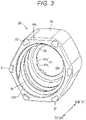
Fig. 3 is a perspective view of the tip end side of a lock adapter ofFig. 2 . -
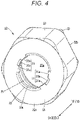
Fig. 4 is a perspective view of the base end side of the lock adapter ofFig. 2 . -
Fig. 5 is a front view of the lock adapter ofFig. 2 . -
Fig. 6 is a partially enlarged perspective view of the vicinity of the nozzle portion of the prefilled syringe ofFig. 2 . -
Fig. 7 is an enlarged view of the nozzle portion of the prefilled syringe ofFig. 2 as viewed from the front side. -
Fig. 8 is a cross-sectional view taken along line VIII-VIII inFig. 6 . -
Fig. 9 is a cross-sectional view of a state in which a cap is screwed into a syringe assembly ofFig. 2 . -
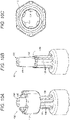
Fig. 10A is a perspective view of a lock adapter and a nozzle portion of a prefilled syringe according to a comparative example.Fig. 10B is a perspective view of the nozzle portion ofFig. 10A. Fig. 10C is a front view of the lock adapter ofFig. 10A . -
Fig. 11 is a front view illustrating claw portions of the lock adapter and a contact portion with an annular rib of the comparative example. -
Fig. 12 is a front view illustrating a claw portion of the lock adapter and a contact portion with an annular rib according to one embodiment. -
Fig. 13 is a cross-sectional view of the contact portion between the claw portion and the annular rib of the lock adapter according to one embodiment. - Hereinafter, preferred embodiments of a
lock adapter 22, asyringe assembly 50, and aprefilled syringe 10 will be described in detail with reference to the accompanying drawings. It should be noted that in the following description, the side of anozzle portion 18 of theprefilled syringe 10 is referred to as the tip end or the tip end side, and the side of aflange portion 16 of theprefilled syringe 10 is referred to as the base end or the base end side. In addition, an alternate long and short dash line A in the drawings represents an axis of theprefilled syringe 10, and the direction of the alternate long and short dash line A is referred to as the axial direction. - As illustrated in
Fig. 1 , theprefilled syringe 10 according to the present embodiment includes asyringe body 12 formed in a cylindrical shape, and alumen 13 extending in the axial direction is formed inside thesyringe body 12. A baseend opening portion 14 through which thelumen 13 opens is provided on the base end side of thesyringe body 12. Agasket 15 is inserted into thelumen 13 from the baseend opening portion 14. - The
gasket 15 is configured slidable in the axial direction while liquid-tightly sealing the inside of thelumen 13, and a portion of thelumen 13 closer to the tip end side than thegasket 15 is a drug chamber that is liquid-tightly sealed by thegasket 15. The drug chamber of thelumen 13 sealed by thegasket 15 is filled with a medicinal solution or a liquid preparation such as injection water or physiological saline for dilution in advance. The prefilledsyringe 10 may be provided to a user in a state where a plunger (not illustrated) is attached, and in such a case, a plunger (pusher) for pressing thegasket 15 may be attached to thegasket 15. As a constituent material of thegasket 15, a rubber material having elasticity, an elastomer material, or the like can be used. - At the base end of the
syringe body 12, theflange portion 16 is formed to protrude radially outward. A finger grip (not illustrated) can be attached to theflange portion 16. In theprefilled syringe 10, the finger grip may be attached to theflange portion 16 in advance. In addition, theflange portion 16 and the finger grip may be integrally formed. - A
neck portion 17 having a diameter smaller than that of thesyringe body 12 is formed at the tip end of thesyringe body 12. From theneck portion 17, thenozzle portion 18 is formed to protrude toward the tip end side. As illustrated inFig. 2 , aflow path 18a is formed inside thenozzle portion 18. Theflow path 18a has an opening at atip end surface 18b of thenozzle portion 18. The base end side of theflow path 18a communicates with thelumen 13. The prefilledsyringe 10 is configured to be capable of discharging a medicinal solution from thetip end surface 18b of thenozzle portion 18. - A
syringe barrel 20 including thesyringe body 12, theflange portion 16, and thenozzle portion 18 is formed of a transparent resin material or glass, which enables thelumen 13 to be visually recognized. Furthermore, a scale for recognizing the liquid amount of the medicinal solution may be provided at the side portion of thesyringe body 12. - As illustrated in
Fig. 1 , thelock adapter 22 and acap 24 are attached to thenozzle portion 18. Thelock adapter 22 is a cylindrical member attached to the outer peripheral portion of thenozzle portion 18. As illustrated inFigs. 2 and3 , afemale screw 25 is formed on an innerperipheral portion 22a of thelock adapter 22. Thecap 24 illustrated inFig. 1 is detachably screwed into thelock adapter 22. As illustrated inFig. 9 , thecap 24 seals the opening portion of theflow path 18a of thenozzle portion 18 in a state of being screwed into thelock adapter 22. When thecap 24 is detached from thelock adapter 22, the tip end of thenozzle portion 18 is exposed, so that it is enabled to connect a connector of a connection tube, a needle module, or the like to thenozzle portion 18. - As illustrated in
Fig. 2 , thelock adapter 22 is attached to the outer peripheral portion of thenozzle portion 18. Thelock adapter 22 is configured slidable in the axial direction within a range of aslide portion 33 provided in thenozzle portion 18. As illustrated inFig. 3 , thelock adapter 22 includes acylindrical body portion 23 formed in a substantially hexagonal cylindrical shape. Acircular insertion hole 23a is formed inside thecylindrical body portion 23. Afemale screw 25 is formed on an innerperipheral portion 22a of thecylindrical body portion 23, the innerperipheral portion 22a facing theinsertion hole 23a. Atip end surface 22b erected perpendicularly to the axial direction is formed on the tip end side of thecylindrical body portion 23. As illustrated inFig. 3 , thetip end surface 22b is formed in a substantially hexagonal shape when viewed from the tip end side, and sixlock protrusions 27 are formed in a portion corresponding to each corner portion of the hexagonal shape so as to protrude toward the tip end. Eachlock protrusion 27 has the outer peripheral side formed in a quarter spherical shape. Thislock protrusion 27 makes contact with ananti-loosening protrusion 40b (seeFig. 9 ) of thecap 24 to prevent loosening of thecap 24. - As illustrated in
Fig. 4 , abase end portion 28 having abase end surface 22c erected perpendicularly to the axial direction is formed on the base end side of thecylindrical body portion 23 of thelock adapter 22. Aclaw portion 30 is formed to protrude from thebase end portion 28 toward the inside of theinsertion hole 23a. As illustrated inFig. 5 , theclaw portion 30 is formed in a circular ring shape (circumferential shape) when viewed from the axial direction, and is integrally formed over the entire circumferential direction. - An inner
peripheral surface 30a (seeFig. 4 ) of theclaw portion 30 is formed to have an inner diameter slightly larger than the outer diameter of theslide portion 33 in order to make theslide portion 33 slidable. Furthermore,rotation restricting portions 31 are formed at some parts of theclaw portion 30 in the circumferential direction. Each of therotation restricting portions 31 has a pair ofrotation restricting protrusions 31a protruding inward from theclaw portion 30. Therotation restricting protrusions 31a are formed so as to protrude inward from the innerperipheral surface 30a of theclaw portion 30. The pair ofrotation restricting protrusions 31a is separated from each other by the same width as that of a rotation restricting rib 36 (seeFig. 6 ) of thenozzle portion 18 described later, and aslide groove 31b configured slidable over therotation restricting rib 36 is formed between the pair ofrotation restricting protrusions 31a. It should be noted that in order to prevent theclaw portion 30 from being divided in the circumferential direction, the position (inner diameter) of the inner periphery of theslide groove 31b is substantially the same as the position (inner diameter) of the innerperipheral surface 30a of theclaw portion 30. Therotation restricting protrusions 31a and theslide groove 31b are engaged with therotation restricting rib 36 to prevent the rotation of thelock adapter 22 in the circumferential direction. - As illustrated in
Fig. 2 , when thelock adapter 22 is moved to the tip end, theclaw portion 30 makes contact with anannular rib 32 to be described later of thenozzle portion 18 to prevent the movement of thelock adapter 22 to the tip end side. That is, the tip end position of thelock adapter 22 is determined by theclaw portion 30. When thelock adapter 22 is moved to the tip end position, thelock adapter 22 covers the periphery of aluer tip 34. Thecap 24, the needle module, the connector, or the like can be connected to thefemale screw 25 on the innerperipheral portion 22a. When thelock adapter 22 is moved to the base end side, the most portion of theluer tip 34 is exposed from thelock adapter 22. - In order to ensure compatibility and to prevent erroneous connection, the position of the
female screw 25 and the position of thetip end surface 22b of thelock adapter 22 in the tip end position of thelock adapter 22 are defined by a corresponding standard. According to ISO 80369-7, which is a standard related to small-diameter syringes, the axial dimension c from thetip end surface 18b of thenozzle portion 18 to thetip end surface 22b of thelock adapter 22 is defined to fall within 2.100 to 2.573 mm. - As a constituent material of the
lock adapter 22, for example, a resin material such as polypropylene, polyethylene, polycarbonate, polyester, or cyclic polyolefin can be used. Among them, a heat-resistant resin such as polypropylene or cyclic polyolefin is preferably used from the viewpoint of preventing deformation during heating in autoclave sterilization. - As illustrated in
Fig. 6 , thenozzle portion 18 to which thelock adapter 22 is attached is formed on the tip end side of theneck portion 17, which is a reduced diameter portion of the tip end of thesyringe body 12. Thenozzle portion 18 includes theslide portion 33 formed on the tip end side of theneck portion 17, theluer tip 34 formed on the tip end side of theslide portion 33, and theannular rib 32 provided along a boundary between theslide portion 33 and theluer tip 34. - The
slide portion 33 is formed between the tip end of theneck portion 17 and the base end of theannular rib 32. Theslide portion 33 is formed in a cylindrical shape having a constant outer diameter size, and has therotation restricting rib 36 and aslide lock portion 38 on an outer peripheral portion thereof. Therotation restricting rib 36 protrudes outward from the outer peripheral portion of theslide portion 33 and extends in the axial direction. Therotation restricting rib 36 is formed over the entire range in the axial direction of theslide portion 33. The radial protrusion height of therotation restricting rib 36 is formed lower than the radial protrusion height of theannular rib 32. That is, therotation restricting rib 36 is formed at such a height that does not divide theannular rib 32 in the circumferential direction. A pair of therotation restricting ribs 36 is formed spaced apart from each other by 180° in the circumferential direction. It should be noted that the number of therotation restricting ribs 36 is not limited to two, and may be one or three or more. - The
slide lock portion 38 includes a tip endconvex portion 38a for holding thelock adapter 22 at the tip end position and a base endconvex portion 38b for holding thelock adapter 22 at the base end position. The tip endconvex portion 38a protrudes at substantially the same height as that of theannular rib 32. As illustrated inFig. 8 , the tip endconvex portion 38a is configured by an inclined surface in which the tip end side and the base end side are inclined with respect to the axial direction, so that theclaw portion 30 of thelock adapter 22 can cross thereover. The tip endconvex portion 38a is formed at a position separated from theannular rib 32 by the axial length of theclaw portion 30, and makes contact with the base end of theclaw portion 30 at the tip end position of thelock adapter 22 to hold thelock adapter 22 at the tip end position. The base endconvex portion 38b is formed in the vicinity of theneck portion 17. The base end side of the base endconvex portion 38b is configured by a steep surface erected perpendicularly to the axial direction, and engages with theclaw portion 30 at the base end position of thelock adapter 22 to hold thelock adapter 22 at the base end position. - As illustrated in
Fig. 6 , theannular rib 32 is formed on the tip end side of theslide portion 33. Theannular rib 32 protrudes to the outer peripheral side of theslide portion 33 and annularly extends in the circumferential direction of thenozzle portion 18. As illustrated inFig. 8 , atip end surface 32a on the tip end side of theannular rib 32 is configured as an inclined surface inclined in the axial direction in order to facilitate attachment of thelock adapter 22. On the other hand, abase end surface 32b of theannular rib 32 is formed of a surface erecting perpendicularly to the axial direction, and is configured such that theclaw portion 30 of thelock adapter 22 cannot cross over theannular rib 32 toward the tip end side. - As illustrated in
Fig. 6 , the protruding height of theannular rib 32 in the outer circumferential direction is higher than that of therotation restricting rib 36 in the outer circumferential direction. That is, theannular rib 32 has a shape that is divided in the circumferential direction by therotation restricting rib 36. In addition, as illustrated inFig. 7 , theannular rib 32 hasnotches 32c each formed by being partially cut out in the circumferential direction in order to facilitate the passage of therotation restricting protrusion 31a of thelock adapter 22 when thelock adapter 22 is attached. Twonotches 32c are provided in each portion adjacent in the circumferential direction to therotation restricting rib 36. - As illustrated in
Fig. 6 , theluer tip 34 is formed in a tapered shape the diameter of which gradually decreases toward the tip end. A needle hub of a needle unit and a connector are connected to theluer tip 34. - As illustrated in
Fig. 9 , thecap 24 is connected to the tip end portion of thenozzle portion 18 and attached so as to cover theluer tip 34. Thecap 24 is a member formed in a bottomed cylindrical shape, and includes abody portion 40 having a cylindrical shape provided on the tip end side, anattachment portion 42 extending in a cylindrical shape from thebody portion 40 to the base end side, and a luertip housing portion 44 formed on the inner peripheral side of theattachment portion 42 and thebody portion 40. Theattachment portion 42 is formed in a cylindrical shape that can be inserted into thelock adapter 22. Amale screw 46 that can be screwed into thefemale screw 25 on the innerperipheral portion 22a of thelock adapter 22 is formed on the outer peripheral portion of theattachment portion 42. - The luer
tip housing portion 44 for housing theluer tip 34 is formed on the inner peripheral side of theattachment portion 42. The luertip housing portion 44 extends to the side of thebody portion 40. Aseal member 48 is attached to the innermost portion of the luertip housing portion 44. Theseal member 48 is made of a rubber material, and when thecap 24 is screwed into the innermost portion, the seal member is elastically compressed and comes into close contact with thetip end surface 18b of thenozzle portion 18 to seal theflow path 18a. - An opposing
surface 40a opposing to thetip end surface 22b of thelock adapter 22 is formed on the base end side of thebody portion 40. The opposingsurface 40a is provided with ananti-loosening protrusion 40b engaging with thelock protrusion 27 to prevent loosening of thecap 24. When thecap 24 is screwed, theanti-loosening protrusion 40b engages with thelock protrusion 27 to keep thecap 24 in a tightly screwed state. Thecap 24 can be formed of a material similar to that of thelock adapter 22. - The
syringe assembly 50 of the present embodiment is configured by attaching thelock adapter 22 to thesyringe body 12. - The
lock adapter 22, thesyringe assembly 50, and theprefilled syringe 10 of the present embodiment are configured as described above, and the operation thereof will be described below. - A plurality of
syringe assemblies 50 are collectively accommodated in a packaging container called a nested tab container in a sterilized state and distributed, and are provided to a sterile filling facility. In the sterile filling facility, filling of each syringe assembly 50 (syringe body 12) with a medicinal solution and capping with thecap 24 and thegasket 15 are performed. Thereafter, autoclave sterilization is performed on thesyringe body 12 in which the medicinal solution is sealed, and theprefilled syringe 10 inFig. 1 is completed. - As described above, the autoclave sterilization of the
prefilled syringe 10 is performed in a state where thecap 24 is screwed into thelock adapter 22. As illustrated inFig. 9 , in a state where thecap 24 is screwed, a load (tightening load) in the direction in which thecap 24 is separated from thenozzle portion 18 acts by the resilient force of theseal member 48. This tightening load is transmitted to thelock adapter 22 through themale screw 46 of thecap 24. Then, as illustrated in an enlarged view ofFig. 13 , the force acts on theclaw portion 30 at a base portion of thelock adapter 22 toward a tip end in the axial direction as indicated by a white arrow. Since a high temperature at the time of autoclave sterilization acts on theclaw portion 30 under a condition where a tightening load through thecap 24 is acting thereon, theclaw portion 30 is easily deformed. - In a
prefilled syringe 100 of a comparative example illustrated inFigs. 10A and 10B , sixrotation restricting ribs 106 are formed on the outer peripheral portion of aslide portion 104 on the base end side of anozzle portion 102. Therotation restricting ribs 106 also serve to reinforce a base portion of thenozzle portion 102, and are formed to protrude outward from anannular rib 110 provided along a boundary with atip portion 108 as illustrated inFig. 10B . Therefore, theannular rib 110 is divided in the circumferential direction by therotation restricting ribs 106. As illustrated inFig. 10C , alock adapter 112 attached to thisnozzle portion 102 has a shape divided in the circumferential direction in such a manner that clawportions 114 on the base end side avoid therotation restricting ribs 106. Therefore, in thelock adapter 112 of the comparative example, theclaw portions 114 have a fragile structure as being divided in the circumferential direction. - As illustrated in
Fig. 11 , theclaw portions 114 of thelock adapter 112 of the comparative example have a risk of receiving the load of thecap 24 in a state of abutting on theannular rib 110 atcontact portions 116 on the inner peripheral side. In this state, theclaw portions 114 are liable to be deformed by high temperature due to autoclave sterilization, and a dimensional error may occur. - In contrast, in the
syringe assembly 50 and theprefilled syringe 10 of the present embodiment, therotation restricting rib 36 is formed lower than the protruding height of theannular rib 32 in thenozzle portion 18. That is, therotation restricting rib 36 does not divide theannular rib 32. Therefore, as illustrated inFig. 12 , it is possible to configure theclaw portion 30 of thelock adapter 22 to have a shape integrally connected in the circumferential direction, so that the rigidity of theclaw portion 30 can be enhanced. As illustrated, in thelock adapter 22 of the present embodiment, thecontact portion 30b makes contact with theannular rib 32. In this manner, the tightening load of thecap 24 is dispersed over a wide range of theclaw portion 30. - As a result, as illustrated in
Fig. 13 , even when autoclave sterilization is performed in a state where the tightening load of thecap 24 acts on theclaw portion 30, deformation of theclaw portion 30 can be suppressed. Furthermore, variations in the axial position of thetip end surface 22b of thelock adapter 22 and the axial position of thefemale screw 25 are suppressed. - The
lock adapter 22, thesyringe assembly 50, and theprefilled syringe 10 of the present embodiment have the following effects. - The
lock adapter 22 of the present embodiment relates to thelock adapter 22 attached on the periphery of thenozzle portion 18 at the tip end of theprefilled syringe 10 and configured slidable in the axial direction of thenozzle portion 18. Thelock adapter 22 includes: thecylindrical body portion 23 formed in a cylindrical shape surrounding the periphery of thenozzle portion 18; and theclaw portion 30 protruding to the inner peripheral side from thebase end portion 28 of thecylindrical body portion 23, and configured to determine the tip end position of thelock adapter 22 by being caught in theannular rib 32 extending in the circumferential direction of thenozzle portion 18. Theclaw portion 30 is formed in a circumferential shape when viewed from the axial direction and is integrally connected in the circumferential direction. - With the above configuration, the rigidity of the
claw portion 30 can be enhanced. In addition, the tightening load of thecap 24 is dispersed over a wide range in the circumferential direction of theclaw portion 30. As a result, even when autoclave sterilization is performed in a state where the tightening load of thecap 24 acts on theclaw portion 30, deformation of theclaw portion 30 can be prevented, and variations in the axial position of thetip end surface 22b of thelock adapter 22 and the axial position of thefemale screw 25 can be suppressed. - The
lock adapter 22 may further include therotation restricting protrusion 31a that protrudes inward from theclaw portion 30 and engages with therotation restricting rib 36 extending in the axial direction of thenozzle portion 18. With this configuration, it is possible to realize a configuration capable of preventing the rotation of thelock adapter 22 without dividing theclaw portion 30 in the circumferential direction. - The
syringe assembly 50 of the present embodiment includes thesyringe body 12 having thelumen 13 capable of accommodating a medicinal solution, thenozzle portion 18 formed at the tip end of thesyringe body 12, and thelock adapter 22 attached to the outer periphery of thenozzle portion 18. In thesyringe assembly 50, thenozzle portion 18 includes theslide portion 33 provided on the base end side and on which thelock adapter 22 is slidable in the axial direction, theluer tip 34 provided on the tip end side of theslide portion 33, and theannular rib 32 extending and protruding in the circumferential direction along the boundary between theluer tip 34 and theslide portion 33. Thelock adapter 22 includes thecylindrical body portion 23 formed in a cylindrical shape surrounding the periphery of thenozzle portion 18, and theclaw portion 30 protruding to the inner peripheral side from thebase end portion 28 of thecylindrical body portion 23, and configured to determine a tip end position of thelock adapter 22 by being caught in theannular rib 32 extending in the circumferential direction of thenozzle portion 18. Theclaw portion 30 of thelock adapter 22 is formed in a circumferential shape when viewed from the axial direction and is integrally connected in the circumferential direction. - With the above-described
syringe assembly 50, the deformation of theclaw portion 30 can be prevented, and variations in the axial position of thetip end surface 22b of thelock adapter 22 and the axial position of thefemale screw 25 can be suppressed. - In the
syringe assembly 50 described above, therotation restricting rib 36 extending in the axial direction is formed on theslide portion 33 of thenozzle portion 18, and the protruding height of therotation restricting rib 36 may be formed lower than the protruding height of theannular rib 32. With the above-described configuration, since it is not necessary to form theclaw portion 30 in the circumferential shape of thelock adapter 22 so as to avoid therotation restricting rib 36, theclaw portion 30 can be integrally formed. As a result, the strength of theclaw portion 30 is improved, and deformation of theclaw portion 30 can be suppressed. - In the
syringe assembly 50 described above, therotation restricting rib 36 may be formed inward of theclaw portion 30 of thelock adapter 22. With this configuration, since therotation restricting rib 36 is positioned inside theclaw portion 30, therotation restricting rib 36 does not interfere with theclaw portion 30, and theclaw portion 30 can be integrally formed in the circumferential direction. - In the
syringe assembly 50 described above, therotation restricting protrusion 31a may be formed that protrudes inward from the innerperipheral surface 30a of theclaw portion 30 of thelock adapter 22 and engages with therotation restricting rib 36. With this configuration, rotation of thelock adapter 22 can be prevented. - In the
syringe assembly 50 described above, thenotch 32c for allowing therotation restricting protrusion 31a to pass therethrough may be formed at a portion adjacent in the circumferential direction to therotation restricting rib 36 of theannular rib 32. With this configuration, upon attaching thelock adapter 22 to thenozzle portion 18, therotation restricting protrusion 31a can easily pass through theannular rib 32, which makes the assembly easy. Furthermore, it is possible to prevent breakage of theannular rib 32 and therotation restricting protrusion 31a at the time of assembly. - In the
syringe assembly 50 described above, thetip end surface 32a of theannular rib 32 is gradually reduced in diameter and inclined toward the tip end side, and thebase end surface 32b of theannular rib 32 may be erected perpendicularly to the axial direction. With this configuration, upon attaching thelock adapter 22 to thenozzle portion 18, theclaw portion 30 can easily cross over theannular rib 32, which is preferable. In addition, since thebase end surface 32b of theannular rib 32 is formed to be erected upright, even when the tightening load of thecap 24 or the like acts on theclaw portion 30, it is possible to prevent theclaw portion 30 from falling off from theannular rib 32 to the tip end side, which is preferable. - The
prefilled syringe 10 of the present embodiment includes thesyringe body 12 accommodating a medicinal solution in thelumen 13, thegasket 15 to be inserted from the base end side of thesyringe body 12 to seal thelumen 13, thenozzle portion 18 formed at the tip end of thesyringe body 12, thelock adapter 22 attached to the outer periphery of thenozzle portion 18, and thecap 24 screwed into thelock adapter 22 to seal thenozzle portion 18. Thenozzle portion 18 of thisprefilled syringe 10 includes theslide portion 33 provided on the base end side and on which thelock adapter 22 is slidable in the axial direction, theluer tip 34 provided on the tip end side of theslide portion 33, and theannular rib 32 extending and protruding in the circumferential direction along the boundary between theluer tip 34 and theslide portion 33. Thelock adapter 22 includes thecylindrical body portion 23 formed in a cylindrical shape surrounding the periphery of thenozzle portion 18, and theclaw portion 30 protruding to the inner peripheral side from thebase end portion 28 of thecylindrical body portion 23, and configured to determine the tip end position of thelock adapter 22 by being caught in theannular rib 32 extending in the circumferential direction of thenozzle portion 18. Theclaw portion 30 of thelock adapter 22 is formed in a circumferential shape when viewed from the axial direction and is integrally connected in the circumferential direction. - With the prefilled
syringe 10 configured as described above, the deformation of theclaw portion 30 can be prevented, and variations in the axial position of thetip end surface 22b of thelock adapter 22 and the axial position of thefemale screw 25 can be suppressed. - Although the present invention has been described above with reference to preferred embodiments, the present invention is not limited to the above embodiments, and it goes without saying that various modifications can be made without departing from the gist of the present invention. For example, in the present embodiment, the lock adapter may be separate from the prefilled syringe and configured to slide, or may be separate and configured not to slide.
Claims (9)
- A lock adapter attached to a periphery of a nozzle portion at a tip end of a prefilled syringe and configured slidable in an axial direction of the nozzle portion, the lock adapter comprising:a cylindrical body portion formed in a cylindrical shape surrounding the periphery of the nozzle portion; anda claw portion protruding to an inner peripheral side from a base end portion of the cylindrical body portion, and configured to determine a tip end position of the lock adapter by being caught in an annular rib extending in a circumferential direction of the nozzle portion, whereinthe claw portion is formed in a circumferential shape when viewed from the axial direction and is integrally connected in the circumferential direction.
- The lock adapter according to claim 1, further comprising a rotation restricting protrusion that protrudes inward from the claw portion and engages with a rotation restricting rib extending in the axial direction of the nozzle portion.
- A syringe assembly comprising:a syringe body having a lumen capable of accommodating a medicinal solution;a nozzle portion formed at a tip end of the syringe body; anda lock adapter attached to an outer periphery of the nozzle portion, whereinthe nozzle portion includes: a slide portion provided on a base end side and on which the lock adapter is slidable in an axial direction; a luer tip provided on a tip end side of the slide portion; and an annular rib extending and protruding in a circumferential direction along a boundary between the luer tip and the slide portion,the lock adapter includes: a cylindrical body portion formed in a cylindrical shape surrounding the periphery of the nozzle portion; and a claw portion protruding to an inner peripheral side from a base end portion of the cylindrical body portion, and configured to determine a tip end position of the lock adapter by being caught in the annular rib extending in the circumferential direction of the nozzle portion, andthe claw portion of the lock adapter is formed in a circumferential shape when viewed from the axial direction and is integrally connected in the circumferential direction.
- The syringe assembly according to claim 3, wherein the slide portion of the nozzle portion is provided with a rotation restricting rib extending in the axial direction, and a protruding height of the rotation restricting rib is formed lower than a protruding height of the annular rib.
- The syringe assembly according to claim 4, wherein the rotation restricting rib is formed inward of the claw portion of the lock adapter.
- The syringe assembly according to claim 4 or 5, wherein a rotation restricting protrusion protruding inward from an inner peripheral portion of the claw portion of the lock adapter so as to engage with the rotation restricting rib is formed.
- The syringe assembly according to claim 6, wherein a notch that allows the rotation restricting protrusion to pass therethrough is formed at a portion of the annular rib adjacent in the circumferential direction to the rotation restricting rib.
- The syringe assembly according to claim 3, wherein a tip end surface of the annular rib is gradually reduced in diameter and inclined toward the tip end side, and a base end surface of the annular rib is erected perpendicularly to the axial direction.
- A prefilled syringe comprising:a syringe body having a lumen accommodating a medicinal solution;a gasket to be inserted from a base end side of the syringe body to seal the lumen;a nozzle portion formed at a tip end of the syringe body;a lock adapter attached to an outer periphery of the nozzle portion; anda cap screwed into the lock adapter to seal the nozzle portion, whereinthe nozzle portion includes: a slide portion provided on a base end side and on which the lock adapter is slidable in an axial direction; a luer tip provided on a tip end side of the slide portion; and an annular rib extending and protruding in a circumferential direction along a boundary between the luer tip and the slide portion;the lock adapter includes: a cylindrical body portion formed in a cylindrical shape surrounding a periphery of the nozzle portion; and a claw portion protruding to an inner peripheral side from a base end portion of the cylindrical body portion, and configured to determine a tip end position of the lock adapter by being caught in the annular rib extending in the circumferential direction of the nozzle portion, andthe claw portion of the lock adapter is formed in a circumferential shape when viewed from the axial direction and is integrally connected in the circumferential direction.
Applications Claiming Priority (2)
| Application Number | Priority Date | Filing Date | Title |
|---|---|---|---|
| JP2020052002 | 2020-03-24 | ||
| PCT/JP2021/008873 WO2021192945A1 (en) | 2020-03-24 | 2021-03-08 | Lock adapter, syringe assembly, and prefilled syringe |
Publications (2)
| Publication Number | Publication Date |
|---|---|
| EP4112102A1 true EP4112102A1 (en) | 2023-01-04 |
| EP4112102A4 EP4112102A4 (en) | 2023-08-02 |
Family
ID=77890084
Family Applications (1)
| Application Number | Title | Priority Date | Filing Date |
|---|---|---|---|
| EP21775747.5A Pending EP4112102A4 (en) | 2020-03-24 | 2021-03-08 | LOCKING ADAPTER, SYRINGE ASSEMBLY AND PRE-FILLED SYRINGE |
Country Status (5)
| Country | Link |
|---|---|
| US (1) | US20230015177A1 (en) |
| EP (1) | EP4112102A4 (en) |
| JP (1) | JP7596361B2 (en) |
| CN (1) | CN114867521B (en) |
| WO (1) | WO2021192945A1 (en) |
Family Cites Families (6)
| Publication number | Priority date | Publication date | Assignee | Title |
|---|---|---|---|---|
| JP4522071B2 (en) * | 2002-10-24 | 2010-08-11 | テルモ株式会社 | Syringe |
| JP4863809B2 (en) | 2006-08-01 | 2012-01-25 | テルモ株式会社 | Prefilled syringe and manufacturing method thereof |
| ES2741662T3 (en) * | 2009-06-24 | 2020-02-11 | Becton Dickinson France | Enhanced Luer Connector |
| US9604012B2 (en) * | 2011-04-20 | 2017-03-28 | Taisei Kako Co., Ltd. | Barrel with cap, pre-filled syringe, and cap with connector |
| JP5962948B2 (en) * | 2011-11-28 | 2016-08-03 | 株式会社ジェイ・エム・エス | Medical syringe |
| WO2015046170A1 (en) * | 2013-09-27 | 2015-04-02 | テルモ株式会社 | Syringe outer cylinder with puncture function, syringe with puncture function, and prefilled syringe with puncture function |
-
2021
- 2021-03-08 EP EP21775747.5A patent/EP4112102A4/en active Pending
- 2021-03-08 WO PCT/JP2021/008873 patent/WO2021192945A1/en not_active Ceased
- 2021-03-08 CN CN202180007483.6A patent/CN114867521B/en active Active
- 2021-03-08 JP JP2022509498A patent/JP7596361B2/en active Active
-
2022
- 2022-09-19 US US17/933,150 patent/US20230015177A1/en active Pending
Also Published As
| Publication number | Publication date |
|---|---|
| JP7596361B2 (en) | 2024-12-09 |
| CN114867521B (en) | 2026-01-02 |
| WO2021192945A1 (en) | 2021-09-30 |
| EP4112102A4 (en) | 2023-08-02 |
| CN114867521A (en) | 2022-08-05 |
| US20230015177A1 (en) | 2023-01-19 |
| JPWO2021192945A1 (en) | 2021-09-30 |
Similar Documents
| Publication | Publication Date | Title |
|---|---|---|
| JP6873173B2 (en) | Adapters for drug delivery devices and methods for mounting the adapters therein | |
| US10159826B2 (en) | Adaptor for a drug delivery device and method for mounting said adaptor thereon | |
| US6957745B2 (en) | Transfer set | |
| EP1267794B1 (en) | Housing capable of connecting a container to a medical device | |
| US6378576B2 (en) | Vial transferset and method | |
| JP5908609B2 (en) | Prefilled syringe outer cylinder and prefilled syringe outer cylinder package | |
| JP2016537064A (en) | Tip cap assembly for closing an injection system | |
| EP3484575B1 (en) | Tip cap assembly, medical injection system and process for producing a medical injection system | |
| RU2003130956A (en) | TRANSITION FITTING FOR USE WITH CUTTERS OF SMALL TARE OF VARIOUS SIZES | |
| JP2002528183A (en) | Cap and luer connector for fluid transfer device | |
| EP2700425A1 (en) | Barrel with attached cap, prefilled syringe, and cap with attached connector | |
| JP2009240684A (en) | Method for manufacturing cap and prefilled syringe | |
| US12071279B2 (en) | Vial closure assembly | |
| US20220354747A1 (en) | Syringe set, syringe, and set | |
| JP4867775B2 (en) | Syringe holder and syringe device | |
| US20230015177A1 (en) | Lock adapter, syringe assembly, and prefilled syringe | |
| EP3603603B1 (en) | Female syringe and syringe kit | |
| JP2010131064A (en) | Container-cum-syringe | |
| JP4299509B2 (en) | Prefilled syringe and prefilled syringe | |
| CN213490571U (en) | Adapter for vials | |
| JP6318691B2 (en) | Medical plug | |
| US20250001099A1 (en) | Syringe outer cylinder, syringe, and prefilled syringe | |
| EP4052746B1 (en) | Syringe-shaped spraying device | |
| WO2024134964A1 (en) | Drug solution dosing device | |
| JP2006081686A (en) | Vial port and chemical kit with the same |
Legal Events
| Date | Code | Title | Description |
|---|---|---|---|
| STAA | Information on the status of an ep patent application or granted ep patent |
Free format text: STATUS: THE INTERNATIONAL PUBLICATION HAS BEEN MADE |
|
| PUAI | Public reference made under article 153(3) epc to a published international application that has entered the european phase |
Free format text: ORIGINAL CODE: 0009012 |
|
| STAA | Information on the status of an ep patent application or granted ep patent |
Free format text: STATUS: REQUEST FOR EXAMINATION WAS MADE |
|
| 17P | Request for examination filed |
Effective date: 20220930 |
|
| AK | Designated contracting states |
Kind code of ref document: A1 Designated state(s): AL AT BE BG CH CY CZ DE DK EE ES FI FR GB GR HR HU IE IS IT LI LT LU LV MC MK MT NL NO PL PT RO RS SE SI SK SM TR |
|
| DAV | Request for validation of the european patent (deleted) | ||
| DAX | Request for extension of the european patent (deleted) | ||
| A4 | Supplementary search report drawn up and despatched |
Effective date: 20230630 |
|
| RIC1 | Information provided on ipc code assigned before grant |
Ipc: A61M 5/32 20060101ALI20230626BHEP Ipc: A61M 5/34 20060101ALI20230626BHEP Ipc: A61M 5/31 20060101ALI20230626BHEP Ipc: A61M 39/10 20060101ALI20230626BHEP Ipc: A61M 5/28 20060101AFI20230626BHEP |
|
| STAA | Information on the status of an ep patent application or granted ep patent |
Free format text: STATUS: EXAMINATION IS IN PROGRESS |
|
| 17Q | First examination report despatched |
Effective date: 20260226 |