JP4867775B2 - Syringe holder and syringe device - Google Patents
Syringe holder and syringe device Download PDFInfo
- Publication number
- JP4867775B2 JP4867775B2 JP2007117298A JP2007117298A JP4867775B2 JP 4867775 B2 JP4867775 B2 JP 4867775B2 JP 2007117298 A JP2007117298 A JP 2007117298A JP 2007117298 A JP2007117298 A JP 2007117298A JP 4867775 B2 JP4867775 B2 JP 4867775B2
- Authority
- JP
- Japan
- Prior art keywords
- syringe
- holder
- main body
- diameter portion
- retaining plate
- Prior art date
- Legal status (The legal status is an assumption and is not a legal conclusion. Google has not performed a legal analysis and makes no representation as to the accuracy of the status listed.)
- Active
Links
Images


Landscapes
- Infusion, Injection, And Reservoir Apparatuses (AREA)
Description
本発明は、注射器(シリンジ)の注射器本体が内挿される注射器ホルダに関する。また、本発明は、注射器と注射器ホルダとからなる注射器装置に関する。 The present invention relates to a syringe holder in which a syringe body of a syringe (syringe) is inserted. The present invention also relates to a syringe device comprising a syringe and a syringe holder.
注射器は、使用する薬液の種類等に応じて、その材料が定められる。薬液が充填される筒状の注射器本体の材料としては、一般に樹脂やガラスが使用されるが、使用する薬液の種類によってはガラスである必要がある。また、近年多用されている、予め所定量の薬液が充填されたプレフィルド型の注射器では、保管中の薬液の変質を防止するために、注射器本体はガラス製であることが要求される。 The material of the syringe is determined according to the type of chemical solution to be used. Resin and glass are generally used as the material for the cylindrical syringe body filled with the chemical solution, but it is necessary to use glass depending on the type of the chemical solution to be used. In addition, in a prefilled syringe that has been frequently used in recent years and is pre-filled with a predetermined amount of a chemical solution, the syringe body is required to be made of glass in order to prevent the chemical solution from being altered during storage.
注射器内に充填された薬液を、その先端のノズルから吐出するためには、注射器本体にプランジャを押し込む操作が必要である。この押し込み操作では、注射器本体に形成された指掛け用フランジに人差し指と中指を掛け、プランジャの後端を親指で押す。従って、この押し込み操作を安定的に行うためには、指掛け用フランジがある程度以上の大きさを有している必要がある。 In order to discharge the drug solution filled in the syringe from the nozzle at the tip, it is necessary to push the plunger into the syringe body. In this pushing operation, the index finger and the middle finger are put on the finger-hanging flange formed on the syringe body, and the rear end of the plunger is pushed with the thumb. Therefore, in order to perform this pushing operation stably, the finger-hanging flange needs to have a certain size or more.
ところが、注射器本体の材料としてガラスを使用する場合に、指掛け用フランジを大きくすると、ガラスが脆性を有するために指掛け用フランジが破損し欠落する、成型が困難である、等の問題が発生する。従って、ガラス製の注射器本体に大きな指掛け用フランジを設けることは困難であり、その結果、ガラス製の注射器本体はプランジャの押し込み操作性が悪いという課題がある。 However, when glass is used as the material for the syringe body, if the finger-hanging flange is made large, the glass is brittle, so that the finger-hanging flange is broken and missing, and molding is difficult. Accordingly, it is difficult to provide a large finger-hanging flange on the glass syringe body, and as a result, the glass syringe body has a problem that the push-in operability of the plunger is poor.
この課題を解決するための提案が特許文献1に記載されており、これを図6を用いて説明する。 A proposal for solving this problem is described in Patent Document 1, which will be described with reference to FIG.
注射器910は、筒状の注射器本体911と、注射器本体911内に摺動可能に挿入されたガスケット912と、ガスケット912にその先端が螺合されたプランジャ913とを備えている。注射器本体911の一端のノズル911aにはキャップ914が装着されており、注射器本体911の他端の外周面には、外径が相対的に太い径大部911bが形成されている。この注射器910は、注射器本体911内に予め薬液が充填されたプレフィルド型の注射器である。
The
注射器910の注射器本体911は、注射器本体911とほぼ同じ長さを有する筒状の注射器ホルダ920に挿入されている。注射器ホルダ920の後端の外周面には、外方向に突出した指掛け用フランジ921が形成されている。指掛け用フランジ921には固定部材925が係止されており、これら指掛け用フランジ921と固定部材925とが注射器本体911の径大部911bを挟持することで、注射器ホルダ920に対する注射器本体911の長手方向の相対的な移動が規制されている。注射器ホルダ920の先端には、内周面に螺旋突条(雌ネジ、図示せず)が形成された止着部922が設けられている。
The
この注射器装置を使用する際には、キャップ914を取り外し、代わりに注射針(図示せず)を注射器本体911の先端のノズル911aに取り付ける。この際、注射針の針基の外周に形成された螺旋突条(雄ネジ)を注射器ホルダ920の止着部922の内周面の螺旋突条と螺合させる(このように、ネジを利用してノズル911aに注射針等をしっかりと接続することを、「ルアーロック接続」という)。その後、注射器ホルダ920に形成された指掛け用フランジ921に人差し指と中指を掛け、プランジャ913の後端を親指で押せば、注射器本体911内に充填された薬液を、ノズル911aに取り付けられた注射針の先端から吐出させることができる。
When using this syringe device, the
注射器ホルダ920は樹脂からなるので、十分に大きな指掛け用フランジ921を形成することができる。従って、プランジャ913の押し込み操作を安定して行うことができる。
Since the
また、注射針の針基が注射器ホルダ920の止着部922と螺合しているので、高粘度の薬液を吐出する際に注射器本体911内に高圧力が発生しても、注射針がノズル911aから抜け落ちることがない。
患者に輸血や輸液を行う場合に、血液や薬液が流れる主送液路に薬液等を混注するために、主送液路に混注用ポートが設けられることが多い。この混注用ポートとしては、スリットが形成されたゴム製の弁体を備え、この弁体のスリットに注射器のノズルを直接差し込むように構成されたニードルレスポートが知られている(このように、注射器のノズルを弁体のスリットに挿入してノズルとポートとを接続することを、「スリップ接続」という)。 When blood transfusion or infusion is performed on a patient, a co-infusion port is often provided in the main liquid supply path in order to co-inject the chemical liquid or the like into the main liquid supply path through which blood or chemical liquid flows. As this mixed injection port, there is known a needleless port that is provided with a rubber valve body in which a slit is formed and in which a nozzle of a syringe is directly inserted into the slit of the valve body (in this way, Connecting the nozzle and the port by inserting the nozzle of the syringe into the slit of the valve body is called “slip connection”).
ところが、図6に示された注射器ホルダ920の止着部922は、注射器910のノズル911aの周囲を取り囲んでいるので、注射器ホルダ920を装着した状態で注射器910のノズル911aをニードルレスポートのスリットに差し込むことはできない。即ち、図6の注射器ホルダ920は、ルアーロック接続を行うことを前提に設計されており、スリップ接続を行うことはできない。
However, since the
注射器910を注射器ホルダ920から取り出せば、注射器910のノズル911aをニードルレスポートに差し込むことは可能であるが、注射器910の径大部911bは指掛け用フランジとしては小さすぎるので、プランジャ913の押し込み操作性は極めて悪くなる。
If the
本発明は、十分に大きな指掛け用フランジを備えることでプランジャの良好な押し込み操作性を確保しながら、ルアーロック接続及びスリップ接続のいずれをも行うことができる注射器ホルダ及び注射器装置を提供することを目的とする。 It is an object of the present invention to provide a syringe holder and a syringe device that can perform both luer lock connection and slip connection while ensuring a good pushing operability of the plunger by providing a sufficiently large finger-hanging flange. Objective.
本発明の注射器ホルダは、一端に薬液を吐出するノズルを備え、他端に径大部を備えた注射器本体が内挿される注射器ホルダであって、一端の内周面に、前記ノズルに接続される注射針と螺合する螺旋突条が形成され、他端又はその近傍の外周面に外方向に突出した指掛け用フランジが形成された筒状のホルダ本体を少なくとも備え、前記ホルダ本体の、前記螺旋突条と前記指掛け用フランジとの間の領域に、前記ホルダ本体をその長手方向に分割することを可能にする切り欠きが形成されていることを特徴とする。 The syringe holder of the present invention is a syringe holder having a nozzle for discharging a chemical solution at one end and a syringe main body having a large diameter portion at the other end, which is connected to the nozzle on the inner peripheral surface of one end. At least a cylindrical holder body formed with a finger hook flange projecting outwardly on the outer peripheral surface at the other end or in the vicinity thereof. A notch that allows the holder body to be divided in the longitudinal direction is formed in a region between the spiral protrusion and the finger-hanging flange.
本発明の注射器装置は、上記の本発明の注射器ホルダと注射器とからなる。 The syringe device of the present invention comprises the above-described syringe holder and syringe of the present invention.
本発明によれば、注射器ホルダの一端の内周面に形成された螺旋突条を用いればルアーロック接続が可能である。また、注射器ホルダを分割してその螺旋突条側の部分を取り除けば注射器のノズルが露出するのでスリップ接続が可能である。更に、ルアーロック接続及びスリップ接続のいずれを行う場合であっても、注射器ホルダの指掛け用フランジを備える部分が注射器本体に搭載されるので、プランジャの良好な押し込み操作性が確保される。 According to the present invention, a luer lock connection is possible by using a spiral protrusion formed on the inner peripheral surface of one end of the syringe holder. Further, if the syringe holder is divided and the spiral protrusion side portion is removed, the nozzle of the syringe is exposed, so that slip connection is possible. Furthermore, even when either the luer lock connection or the slip connection is performed, the portion of the syringe holder that includes the finger hooking flange is mounted on the syringe main body, so that a good pushing operability of the plunger is ensured.
上記の本発明の注射器ホルダにおいて、前記ホルダ本体の前記他端の内周面には、内径が前記注射器本体の前記径大部の外径より大きな大内径部が形成され、前記大内径部の前記螺旋突条側には、内径が前記注射器本体の前記径大部の外径より小さな小内径部が形成されていることが好ましい。ホルダ本体の他端に大内径部を備えることにより、ホルダ本体内に注射器本体の径大部を収納することができる。また、ホルダ本体が、大内径部の螺旋突条側に小内径部を備えることにより、プランジャの押し込み操作時に注射器本体が注射器ホルダに対して螺旋突条側に移動するのを規制することができる。 In the syringe holder according to the present invention, a large inner diameter portion having an inner diameter larger than an outer diameter of the large diameter portion of the syringe main body is formed on an inner peripheral surface of the other end of the holder main body. It is preferable that a small inner diameter portion having an inner diameter smaller than the outer diameter of the large diameter portion of the syringe main body is formed on the spiral protrusion side. By providing the large inner diameter portion at the other end of the holder main body, the large diameter portion of the syringe main body can be accommodated in the holder main body. Further, since the holder main body includes the small inner diameter portion on the spiral protrusion side of the large inner diameter portion, it is possible to restrict the syringe body from moving toward the spiral protrusion side with respect to the syringe holder during the pushing operation of the plunger. .
上記の本発明の注射器ホルダが、前記ホルダ本体の前記他端に、前記注射器本体の前記径大部よりも小径の貫通孔が形成された抜け止め板を更に備えることが好ましい。これにより、注射器ホルダに内挿された注射器本体が、螺旋突条とは反対側端から抜け落ちるのを防止することができる。 It is preferable that the syringe holder of the present invention further includes a retaining plate in which a through hole having a smaller diameter than the large diameter portion of the syringe body is formed at the other end of the holder body. Thereby, the syringe main body inserted in the syringe holder can be prevented from falling off from the end opposite to the spiral protrusion.
上記の本発明の注射器ホルダが、前記ホルダ本体の前記他端に抜け止め板を更に備え、前記注射器本体の前記径大部が、前記ホルダ本体及び前記抜け止め板により挟持されることが好ましい。これにより、注射器ホルダに内挿された注射器本体が注射器ホルダに対して長手方向に移動することなく保持される。 Preferably, the syringe holder of the present invention further includes a retaining plate at the other end of the holder body, and the large-diameter portion of the syringe body is sandwiched between the holder body and the retaining plate. Thereby, the syringe main body inserted in the syringe holder is held without moving in the longitudinal direction with respect to the syringe holder.
この場合において、前記ホルダ本体及び前記抜け止め板に、互いに係合し合う係合構造が設けられていることが好ましい。これにより、ホルダ本体に抜け止め板を容易に固定することができるので、注射器ホルダの組立が容易なる。 In this case, it is preferable that an engagement structure that engages with each other is provided on the holder body and the retaining plate. Thereby, since the retaining plate can be easily fixed to the holder body, the assembly of the syringe holder is facilitated.
上記の本発明の注射器ホルダにおいて、前記ホルダ本体と前記抜け止め板とがヒンジを介して一体に成形されていることが好ましい。これにより、注射器ホルダを一部品で構成することができるので、部品の管理や組立が容易になり、生産コストを低減することができる。 In the syringe holder of the present invention described above, it is preferable that the holder body and the retaining plate are integrally formed via a hinge. Thereby, since a syringe holder can be comprised by one component, management and assembly of components become easy and production cost can be reduced.
以下、本発明を具体的な実施形態を示しながら詳細に説明する。 Hereinafter, the present invention will be described in detail with reference to specific embodiments.
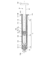
図1は、本発明の一実施形態に係る注射器装置の概略構成を示した底面図、図2は、図1のII−II線での注射器装置の矢視断面図である。本実施形態の注射器装置は、注射器10と注射器ホルダ100とからなる。
FIG. 1 is a bottom view showing a schematic configuration of a syringe apparatus according to an embodiment of the present invention, and FIG. 2 is a cross-sectional view of the syringe apparatus taken along line II-II in FIG. The syringe device according to this embodiment includes a
注射器10は、筒状の注射器本体11と、注射器本体11内に配されたガスケット12と、注射器本体11内に挿入されたプランジャ13とを備えている。
The
注射器本体11は、その一端(以下、「前端」という)に薬液が吐出されるノズル11aを備え、他端(以下、「後端」という)に径大部11bを備える。ノズル11a及び径大部11bを除く注射器本体11の部分は、外径が一定の円筒形状を有し、この部分を円筒部11cと呼ぶ。円筒部11cの外径に比べて、ノズル11aの外径は小さく、径大部11bの外径は大きい。
The
プランジャ13は、その一端の雄ネジ13aと、他端の皿状の押板13bと、これらを繋ぐ軸部13cとを備える。軸部13cの雄ネジ13aに隣接する部分13c1の外径は、これ以外の部分13c2の外径よりも僅かに大きい。
The
ガスケット12のプランジャ13a側端面には雌ネジが形成されている。この雌ネジとプランジャ13の先端に形成された雄ネジ13aとを螺合させることにより、ガスケット12とプランジャ13とが結合されている。プランジャ13を注射器本体11に対して抜き差しすると、ガスケット12はその外周面が注射器本体11の円筒状の内周面に密着しながら、注射器本体11内をその長手方向に摺動する。
A female screw is formed on the end face of the gasket 12 on the plunger 13a side. The gasket 12 and the
図1及び図2に示した注射器10は、ガスケット12と、これよりノズル11a側の注射器本体11とで形成された空間内に薬液が充填されたプレフィルド型の注射器である。ノズル11aには、充填された薬液が漏れ出るのを防止するためにキャップ14が装着されている。
The
注射器本体11の材料は、特に制限はないが、例えば、透明性が高く、耐薬品性の高い樹脂またはガラスが好ましい。樹脂としては、例えば、環状ポリオレフィン、ポリカーボネート、ポリエチレンテレフタレート、ポリプロピレン、ポリエチレンナフタレート等が好ましい。ノズル11aは、ISO594−1に規定の100分の6テーパー面を有していると好ましい。
The material of the
ガスケット12の材料は、特に制限はないが、例えば、ブチルゴム、スチレン系熱可塑性エラストマー等が好ましい。 The material of the gasket 12 is not particularly limited, but for example, butyl rubber, styrene thermoplastic elastomer, and the like are preferable.
プランジャ13の材料は、特に制限はないが、例えば、ポリプロピレン、ポリエチレン等の樹脂が好ましい。
The material of the
キャップ14の材料は、特に制限はないが、弾性材料が好ましく、例えば、ブチルゴム、スチレン系熱可塑性エラストマー等が好ましい。
The material of the
注射器10の注射器本体11は注射器ホルダ100に内挿されている。
The
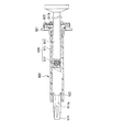
図3は、注射器本体11が内挿される前の注射器ホルダ100の底面図である。図4(A)は、図3のIVA−IVA線に沿った注射器ホルダ100の矢視断面図、図4(B)は本発明の一実施形態に係る注射器ホルダ100の背面図である。
FIG. 3 is a bottom view of the
注射器ホルダ100はホルダ本体110と抜け止め板130とを備え、これらはヒンジ119を介して一体に成形されている。一点鎖線110aはホルダ本体110の中心軸を示す。
The
ホルダ本体110は、全体して筒状である。ホルダ本体110の中心軸110a方向の一端(以下、「前端」という)の内周面には螺旋突条(雌ネジ)112が形成され、その他端(以下、「後端」という)の内周面には内径が拡大された大内径部113が形成されている。ホルダ本体100の、螺旋突条112が形成された部分を止着部111と呼ぶ。ホルダ本体110の、止着部111と大内径部113との間の部分は、内径が一定の円筒状の内周面を有し、この部分を小内径部114と呼ぶ。小内径部114の内径は、これと後端側に隣接する大内径部113の内径よりも小さく、これと前端側に隣接する止着部111の螺旋突条112の内径(即ち、雌ネジの山径)よりも大きい。螺旋突条112、小内径部114、及び大内径部113の各中心軸は中心軸110aと一致する。
The
ホルダ本体110の後端の外周面には外方向(中心軸110aに直交する方向)に突出した指掛け用フランジ117が形成されている。中心軸110a方向において、大内径部113と指掛け用フランジ117とはほぼ同じ位置に形成されている。これにより、ホルダ本体110に強度が低い薄肉部が形成されるのを防止している。
A
止着部111の螺旋突条112の内径は、注射器本体11のノズル11aの外径よりも大きく、注射器本体11の円筒部11cの外径よりも小さい。また、小内径部114の内径は、注射器本体11の円筒部11cの外径よりも大きく、注射器本体11の径大部11bの外径よりも小さい。これにより、ホルダ本体110に内挿された注射器本体11が、ホルダ本体110に対して止着部111側に相対的に移動するのを防止している。
The inner diameter of the
また、大内径部113の内径は、注射器本体11の径大部11bの外径よりも大きい。これにより、大内径部113に注射器本体11の径大部11bを収納することができる。
Further, the inner diameter of the large
ホルダ本体110の止着部111と大内径部113との間の領域には、ホルダ本体110を中心軸110a方向に分割することを可能にする切り欠き115が形成されている。
A
止着部111の外周面には、中心軸110aと平行な複数の畝状突起116が形成されている。畝状突起116は、ホルダ本体110を指で挟んでルアーロック接続をする際の滑り止めとして機能する。但し、止着部111の外周面には複数の畝状突起116以外の滑り止め機能を有する形状が形成されていても良く、あるいは滑らかな円筒面であっても良い。
A plurality of hook-shaped
抜け止め板130は、指掛け用フランジ117に設けられたヒンジ119に接続されている。抜け止め板130は、ヒンジ119を中心として回動させて、指掛け用フランジ117に重ね合わせることができる(図1、図2参照)。
The retaining
指掛け用フランジ117及び抜け止め板130には互いに係合し合う係合構造が設けられている。この係合構造は、指掛け用フランジ117の後端側の面に突出した一対の係止用爪118と、抜け止め板130に形成された一対の係止用穴131とからなる。指掛け用フランジ117に抜け止め板130を重ね合わせると、一対の係止用爪118が一対の係止用穴131内に嵌入し、一対の係止用爪118の鉤形状が一対の係止用穴131の端縁と係合する。かくして、一対の係止用爪118と一対の係止用穴131とからなる係合構造は、指掛け用フランジ117と抜け止め板130との密着固定状態を保持する。
The
抜け止め板130には、貫通孔133が形成されている。抜け止め板130が指掛け用フランジ117に重ね合わされ、一対の係止用爪118と一対の係止用穴131の端縁とが係合したとき、貫通孔133の中心は、ホルダ本体110の中心軸110aと一致する。
A through
貫通孔133の内径は、注射器本体11の径大部11bの外径よりも小さい。これにより、注射器本体11が抜け止め板130の貫通孔133を通って注射器ホルダ100から抜け落ちるのを防止できる。
The inner diameter of the through
また、貫通孔133の内径は、プランジャ13の雄ネジ13aに隣接する部分13c1の外径より僅かに小さく、これ以外の部分13c2の外径より大きい。これにより、抜け止め板130の貫通孔133にプランジャ13を一端挿入した後は、プランジャ13が抜け止め板130から抜け落ちるのを防止している。
Further, the inner diameter of the through-
ホルダ本体110の長手方向の寸法は、注射器本体11のそれとほぼ同じである。図2に示したようにホルダ本体110に注射器本体11が挿入された状態において、注射器本体11のノズル11a、円筒部11c、径大部11bが、ホルダ本体110の止着部111、小内径部114、大内径部113とそれぞれ中心軸110a方向の位置がほぼ一致するように、止着部111、小内径部114、大内径部113のそれぞれの長手方向の寸法が設定されている。
The length of the
ホルダ本体110及び抜け止め板130の材料は、特に制限はないが、例えば、透明性が高く、成形性が良好で、軽量な樹脂が好ましい。ホルダ本体110が高い透明性を有することにより、内挿された注射器本体11内の薬液や、その外周面に貼付されたラベルを透視することができる。また、成形性が良好な材料を用いることにより、十分な大きさの指掛け用フランジ117や、複雑な形状を有する指掛け用フランジ117と抜け止め板130との係合構造を容易に形成することができる。樹脂としては、例えば、ポリカーボネート、ポリプロピレン、ポリエチレンナフタレート、ポリエチレンテレフタレート等が好ましい。螺旋突条112はISO594−2に規定された螺旋突状であると好ましい。
The material of the holder
次に、プレフィルド型の注射器を用いた本発明の注射器装置(図1及び図2参照)の組立方法の一例を説明する。 Next, an example of a method for assembling the syringe device (see FIGS. 1 and 2) of the present invention using a prefilled syringe will be described.
まず、注射器10を構成する注射器本体11、ガスケット12、キャップ14をそれぞれ単品で洗浄し、滅菌する。
First, the
次いで、注射器本体11のノズル11aにキャップ14を装着する。そして、注射器本体11内に、その径大部11b側の開口から、薬液を所定量充填し、続いてガスケット12を挿入する。かくして、注射器本体11内の密閉空間内に薬液が保持される。これらの工程は、衛生状態が厳密に管理された雰囲気で行われる。薬液が耐熱性を有している場合には、薬液が充填保持された注射器本体11を高温蒸気で滅菌しても良い。
Next, the
次いで、図4(A)及び図4(B)に示した注射器ホルダ100のホルダ本体110に、その大内径部113側から、薬液が充填保持された注射器本体11をそのノズル11aを前にして挿入する。そして、抜け止め板130をヒンジ119を中心として回動させて指掛け用フランジ117に重ね合わせ、一対の係止用爪118と一対の係止用穴131の端縁とを係合する。そして、抜け止め板130の貫通孔133にプランジャ13を挿入し、その先端の雄ネジ13aをガスケット12の雌ネジに螺入し、プランジャ13とガスケット12とを結合する。かくして、図1及び図2に示した注射器装置が得られる。この注射器装置は所定の包装が施されて出荷される。この後は、注射器本体11が注射器ホルダ100に内挿された状態で取り扱われるので、注射器本体11がガラス製であってもその破損を防止することができる。
Next, the
次に、プレフィルド型の注射器を用いた発明の注射器装置の使用方法の一例を説明する。 Next, an example of a method of using the syringe device of the invention using a prefilled syringe will be described.
最初に、注射器10のノズル11aに、注射針や、三方活栓などの一部を構成する雌ルアーをルアーロック接続する場合を説明する。まず、図1及び図2の状態において、ノズル11aに取り付けられたキャップ14を取り外す。次いで、注射針の針基の内腔又は雌ルアーの先端の内腔にノズル11aを挿入し、且つ、注射針の針基の外周に形成された螺旋突条又は雌ルアーの先端の外周に形成された螺旋突条とホルダ本体110の止着部111の内周面に形成された螺旋突条112とを螺合する。そして、ホルダ本体110に形成された指掛け用フランジ117に人差し指と中指を掛け、プランジャ13の押板13bを親指で押して、注射器本体11内に充填された薬液を、ノズル11aに取り付けられた注射針又は雌ルアーを介して吐出させる。
First, a description will be given of a case where a female luer constituting a part of an injection needle, a three-way cock, or the like is connected to the
注射器ホルダ100に形成された指掛け用フランジ117は、プランジャ13の押し込み操作を行うのに十分な大きさを有している。従って、押し込み操作を安定して行うことができる。また、ホルダ本体110の螺旋突条112を利用してルアーロック接続を行うことができるので、注射器本体11内に充填された薬液が高粘度を有するために吐出時に注射器本体11内に高圧力が発生しても、注射針や雌ルアーが抜け落ちることがない。
The finger-hanging
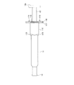
次に、注射器10のノズル11aをニードルレスポートのゴム製の弁体に設けられたスリットに挿入してスリップ接続する場合を説明する。まず、図1及び図2の状態において、ホルダ本体110の切り欠き115に対して前端側部分と後端側部分とを把持し、ホルダ本体110に捩り力を加えて、切り欠き115が形成された箇所でホルダ本体110をねじ切り、前端側部分と後端側部分とに2分割する。そして、ホルダ本体110の前端側部分を取り除く。かくして、図5に示すように、注射器本体11の前端側の部分が露出する。図5において、110’はホルダ本体110の後端側部分(以下「ホルダ本体後端側片」という)である。次いで、ノズル11aに取り付けられたキャップ14を取り外し、ノズル11aをニードルレスポートのゴム製の弁体に設けられたスリットに挿入する。そして、指掛け用フランジ117に人差し指と中指を掛け、プランジャ13の押板13bを親指で押して、注射器本体11内に充填された薬液をノズル11aから吐出させる。
Next, a case where the
上述したように、図6に示した従来の注射器ホルダ920の止着部922は、スリップ接続を行う際に邪魔になっていた。これに対して、本実施形態では、ホルダ本体110を長手方向に2分割し、ノズル11aの周囲を取り囲む止着部111を含むホルダ本体110の前端側部分を取り除く。従って、ノズル11aをニードルレスポートの弁体のスリットに挿入してスリップ接続を行うことができる。
As described above, the
しかも、注射器本体11に指掛け用フランジ117を含むホルダ本体後退側片110’が装着されており、注射器本体11の径大部11bはホルダ本体後退側片110’と抜け止め板130とで挟持されている。従って、ホルダ本体後退側片110’の指掛け用フランジ117を利用してプランジャ13の押し込み操作を安定して行うことができ、押し込み操作性はルアーロック接続した場合と何ら変わらない。
Moreover, the holder main body retracting
以上のように、本発明によれば、ホルダ本体110の先端に螺旋突条112が形成されているので、注射器10のノズル11aをルアーロック接続することができる。また、ホルダ本体110の切り欠き115の部分でホルダ本体110を2分割し、前端側部分を取り除けば、注射器10のノズル11aをスリップ接続することができる。ホルダ本体110は、切り欠き115よりも後端側に十分に大きな指掛け用フランジ117を備えているので、ルアーロック接続及びスリップ接続のいずれを行う場合であっても、プランジャ13の押し込み操作性は良好である。
As described above, according to the present invention, since the
上記の実施形態は一例であり、本発明はこれに限定されない。 The above-described embodiment is an example, and the present invention is not limited to this.
例えば、ホルダ本体110を分割するためにホルダ本体110に形成された切り欠き115の形状は、図3及び図4に示した長方形の他に、円形、楕円形、三角形、各種多角形など任意の形状であっても良い。また、切り欠きの数はホルダ本体110を分割するのに要する力などを考慮して適宜設定することができる。また、切り欠きの長手方向は、図3及び図4に示したようにホルダ本体110の周方向に一致している必要はなく、中心軸110aと平行であっても良く、あるいは、螺旋状に切り欠きを延設しても良い。また、ホルダ本体110の切り欠き115が形成された部分の肉厚を薄くして、ホルダ本体110の分割性を向上させても良い。
For example, the shape of the
また、中心軸110a方向において異なる複数の位置に切り欠き115をそれぞれ形成して、使用者がホルダ本体110の分割位置を適宜選択できるようにしても良い。
Further,
指掛け用フランジ117の形状や大きさなどは、上記の実施形態に限定されず、プランジャ13の押し込み操作性を考慮して適宜変更可能である。
The shape, size, and the like of the
上記の実施形態では、指掛け用フランジ117はホルダ本体110の後端に設けられていたが、指掛け用フランジ117の中心軸110a方向における位置は、ホルダ本体110の後端である必要はなく、切り欠き115よりも後端側であればいずれでも良い。この場合、抜け止め板130をホルダ本体110の後端に係止するための係合構造は、ホルダ本体110の指掛け用フランジ117以外の箇所に設けられても良く、また、抜け止め板130は、ホルダ本体110の指掛け用フランジ117以外の部分とヒンジ119を介して接続されていても良い。
In the above embodiment, the
上記の実施形態では、抜け止め板130はヒンジ119を介してホルダ本体110と一体であったが、抜け止め板130とホルダ本体110とが別体であってもよい。
In the above embodiment, the retaining
上記の実施形態では、ホルダ本体110の後端の内周面に大内径部113が形成されていたが、大内径部113が形成されていなくても良い。本発明では、注射器本体11の径大部11bをホルダ本体110と抜け止め板130とで中心軸110a方向に挟持できればよい。例えば、ホルダ本体110の後端に大内径部113を形成せずに、抜け止め板130のホルダ本体110側の面に注射器本体11の径大部11bを収納する凹部を形成することもできる。
In the above embodiment, the large
ホルダ本体110と抜け止め板130とに設けられる係合構造は、抜け止め板130をホルダ本体110に固定できれば、上記の実施形態に限定されない。例えば、抜け止め板130に係止用爪を設け、指掛け用フランジ117にこの係止用爪が嵌入する係止用穴を設けても良い。この場合、指掛け用フランジ117の指が当たる面に突出した係止用爪を滑り止めとして機能させることができる。また、ホルダ本体110と抜け止め板130とを別体として、両者の係合構造が螺合構造であっても良い。
The engagement structure provided in the holder
上記の実施形態では、注射器ホルダ100はホルダ本体110と抜け止め板130とを備えていたが、抜け止め板130を省略することは可能である。抜け止め板130を省略しても、ルアーロック接続及びスリップ接続のいずれもが可能であり、しかも、いずれの場合であってもプランジャ13の良好な押し込み操作性が得られる。
In the above embodiment, the
上記の実施形態では、注射器10がプレフィルド型の注射器である場合を例に説明したが、薬液が予め充填されていない注射器にも本発明を適用するすることは可能である。
In the above embodiment, the case where the
本発明の利用分野は特に制限はないが、大きな指掛け用フランジを形成することができないガラス製の注射器本体を備えた注射器に利用されると本発明の効果が顕著に発現するので好ましい。 Although the field of use of the present invention is not particularly limited, it is preferable to use the present invention for a syringe provided with a glass syringe body that cannot form a large finger-hanging flange because the effects of the present invention are remarkably exhibited.
10 注射器
11 注射器本体
11a ノズル
11b 径大部
11c 円筒部
12 ガスケット
13 プランジャ
13a 雄ネジ
13b 押板
13c 軸部
14 キャップ
100 注射器ホルダ
110 ホルダ本体
110a ホルダ本体の中心軸
111 止着部
112 螺旋突条
113 大内径部
114 小内径部
115 切り欠き
116 畝状突起
117 指掛け用フランジ
118 係止用爪
119 ヒンジ
130 抜け止め板
131 係止用穴
133 貫通孔
DESCRIPTION OF
Claims (7)
一端の内周面に、前記ノズルに接続される注射針と螺合する螺旋突条が形成され、他端又はその近傍の外周面に外方向に突出した指掛け用フランジが形成された筒状のホルダ本体を少なくとも備え、
前記ホルダ本体の、前記螺旋突条と前記指掛け用フランジとの間の領域に、前記ホルダ本体をその長手方向に分割することを可能にする切り欠きが形成されていることを特徴とする注射器ホルダ。 A syringe holder having a nozzle for discharging a chemical solution at one end and a syringe body having a large diameter portion at the other end,
A cylindrical ridge formed on the inner peripheral surface of one end is formed with a spiral ridge to be screwed with the injection needle connected to the nozzle, and is formed with an outwardly protruding finger hooking flange on the outer peripheral surface of the other end or the vicinity thereof. At least a holder body,
A syringe holder characterized in that a notch that allows the holder body to be divided in the longitudinal direction is formed in a region of the holder body between the spiral protrusion and the finger-hanging flange. .
Priority Applications (1)
| Application Number | Priority Date | Filing Date | Title |
|---|---|---|---|
| JP2007117298A JP4867775B2 (en) | 2007-04-26 | 2007-04-26 | Syringe holder and syringe device |
Applications Claiming Priority (1)
| Application Number | Priority Date | Filing Date | Title |
|---|---|---|---|
| JP2007117298A JP4867775B2 (en) | 2007-04-26 | 2007-04-26 | Syringe holder and syringe device |
Publications (2)
| Publication Number | Publication Date |
|---|---|
| JP2008272084A JP2008272084A (en) | 2008-11-13 |
| JP4867775B2 true JP4867775B2 (en) | 2012-02-01 |
Family
ID=40050830
Family Applications (1)
| Application Number | Title | Priority Date | Filing Date |
|---|---|---|---|
| JP2007117298A Active JP4867775B2 (en) | 2007-04-26 | 2007-04-26 | Syringe holder and syringe device |
Country Status (1)
| Country | Link |
|---|---|
| JP (1) | JP4867775B2 (en) |
Families Citing this family (7)
| Publication number | Priority date | Publication date | Assignee | Title |
|---|---|---|---|---|
| EP2790752B1 (en) * | 2011-12-15 | 2018-08-08 | SHL Group AB | Auto-injection device |
| KR20170137849A (en) * | 2015-04-17 | 2017-12-13 | 코와 가부시키가이샤 | Guide lens insertion mechanism |
| US10576207B2 (en) | 2015-10-09 | 2020-03-03 | West Pharma. Services IL, Ltd. | Angled syringe patch injector |
| CN113648488B (en) | 2015-10-09 | 2024-03-29 | 西医药服务以色列分公司 | Curved fluid path attachment to prefilled fluid reservoir |
| JP6885960B2 (en) | 2016-01-21 | 2021-06-16 | ウェスト ファーマ サービシーズ イスラエル リミテッド | Drug delivery device with visual indicators |
| KR101852718B1 (en) * | 2017-04-04 | 2018-05-18 | 주식회사 제네웰 | Kit for pain reduction of incision site after surgical operation |
| JP6979840B2 (en) * | 2017-09-29 | 2021-12-15 | テルモ株式会社 | Syringe, Syringe for Prefilled Syringe and Prefilled Syringe |
Family Cites Families (6)
| Publication number | Priority date | Publication date | Assignee | Title |
|---|---|---|---|---|
| JP3595895B2 (en) * | 1996-11-29 | 2004-12-02 | 生化学工業株式会社 | Syringe holder and syringe using the holder |
| FR2876035B1 (en) * | 2003-11-14 | 2007-03-30 | Plastic Omnium Cie | SAFETY ASSEMBLY FOR EQUIPPING A SYRINGE AND SYRINGE ASSEMBLY |
| US20050148944A1 (en) * | 2003-12-24 | 2005-07-07 | Hsin-Po Hsieh | Syringe safety sleeve |
| JP2005296141A (en) * | 2004-04-07 | 2005-10-27 | Jms Co Ltd | Syringe with connector and connector |
| EP1733749A4 (en) * | 2004-04-07 | 2013-09-04 | Jms Co Ltd | Syringe with connector, connector for syringe, and syringe |
| US7255689B2 (en) * | 2004-10-29 | 2007-08-14 | Safety Syringes, Inc. | Syringe with anti-rotation for luer lock |
-
2007
- 2007-04-26 JP JP2007117298A patent/JP4867775B2/en active Active
Also Published As
| Publication number | Publication date |
|---|---|
| JP2008272084A (en) | 2008-11-13 |
Similar Documents
| Publication | Publication Date | Title |
|---|---|---|
| JP4867775B2 (en) | Syringe holder and syringe device | |
| CN105939744B (en) | Plunger assembly comprising a plunger rod or the like for advancing a stopper through a syringe | |
| CN101448537B (en) | Injection device | |
| JP6731909B2 (en) | Packaging and packaging assembly | |
| CN102573959B (en) | Syringe assembly with pivoting plunger and integral tip guard | |
| US11633543B2 (en) | Device for locking a plunger rod of a syringe after use and preventing re-use of the syringe, and syringe assembly | |
| JP4757951B1 (en) | Two-chamber syringe | |
| CN107427639B (en) | Syringe Holders and Administration Assemblies | |
| CN102821735A (en) | Connector and connector assembly | |
| US10512591B2 (en) | Cartridge assembly for an injection system | |
| JP2009077943A (en) | Syringe holder and syringe device | |
| JP6486276B2 (en) | Syringe outer cylinder with puncture function, syringe with puncture function and prefilled syringe with puncture function | |
| JP6417007B2 (en) | Connections and medical kits | |
| JP6318531B2 (en) | Male connector, female connector, and connector set | |
| JP6046721B2 (en) | Liquid dosing device | |
| JP4584057B2 (en) | Prefilled syringe | |
| JP5411729B2 (en) | Drug administration device | |
| WO2016021323A1 (en) | Needle assembly | |
| CN105148358B (en) | Multi-component container | |
| JP4656784B2 (en) | Prefilled syringe | |
| JP3136621U (en) | Aid for syringe with flange | |
| JP4158446B2 (en) | Filled bellows container | |
| WO2017170634A1 (en) | Seal member, syringe assembly, and prefilled syringe | |
| EP2140899A1 (en) | Injector doubling as container | |
| JP2008110025A (en) | Injection device |
Legal Events
| Date | Code | Title | Description |
|---|---|---|---|
| A621 | Written request for application examination |
Free format text: JAPANESE INTERMEDIATE CODE: A621 Effective date: 20090415 |
|
| A131 | Notification of reasons for refusal |
Free format text: JAPANESE INTERMEDIATE CODE: A131 Effective date: 20110315 |
|
| A977 | Report on retrieval |
Free format text: JAPANESE INTERMEDIATE CODE: A971007 Effective date: 20110322 |
|
| TRDD | Decision of grant or rejection written | ||
| A01 | Written decision to grant a patent or to grant a registration (utility model) |
Free format text: JAPANESE INTERMEDIATE CODE: A01 Effective date: 20111018 |
|
| A01 | Written decision to grant a patent or to grant a registration (utility model) |
Free format text: JAPANESE INTERMEDIATE CODE: A01 |
|
| A61 | First payment of annual fees (during grant procedure) |
Free format text: JAPANESE INTERMEDIATE CODE: A61 Effective date: 20111031 |
|
| R150 | Certificate of patent or registration of utility model |
Ref document number: 4867775 Country of ref document: JP Free format text: JAPANESE INTERMEDIATE CODE: R150 Free format text: JAPANESE INTERMEDIATE CODE: R150 |
|
| FPAY | Renewal fee payment (event date is renewal date of database) |
Free format text: PAYMENT UNTIL: 20141125 Year of fee payment: 3 |
|
| R250 | Receipt of annual fees |
Free format text: JAPANESE INTERMEDIATE CODE: R250 |
|
| R250 | Receipt of annual fees |
Free format text: JAPANESE INTERMEDIATE CODE: R250 |
|
| R250 | Receipt of annual fees |
Free format text: JAPANESE INTERMEDIATE CODE: R250 |
|
| R250 | Receipt of annual fees |
Free format text: JAPANESE INTERMEDIATE CODE: R250 |
|
| R250 | Receipt of annual fees |
Free format text: JAPANESE INTERMEDIATE CODE: R250 |
|
| R250 | Receipt of annual fees |
Free format text: JAPANESE INTERMEDIATE CODE: R250 |
|
| R250 | Receipt of annual fees |
Free format text: JAPANESE INTERMEDIATE CODE: R250 |
|
| R250 | Receipt of annual fees |
Free format text: JAPANESE INTERMEDIATE CODE: R250 |
|
| R250 | Receipt of annual fees |
Free format text: JAPANESE INTERMEDIATE CODE: R250 |
|
| R250 | Receipt of annual fees |
Free format text: JAPANESE INTERMEDIATE CODE: R250 |
|
| R250 | Receipt of annual fees |
Free format text: JAPANESE INTERMEDIATE CODE: R250 |