EP4111894A1 - Upper cover assembly, and atomizer and aerosol generating device therefor - Google Patents
Upper cover assembly, and atomizer and aerosol generating device therefor Download PDFInfo
- Publication number
- EP4111894A1 EP4111894A1 EP21759751.7A EP21759751A EP4111894A1 EP 4111894 A1 EP4111894 A1 EP 4111894A1 EP 21759751 A EP21759751 A EP 21759751A EP 4111894 A1 EP4111894 A1 EP 4111894A1
- Authority
- EP
- European Patent Office
- Prior art keywords
- sliding
- upper cover
- cover
- mouthpiece
- locking member
- Prior art date
- Legal status (The legal status is an assumption and is not a legal conclusion. Google has not performed a legal analysis and makes no representation as to the accuracy of the status listed.)
- Withdrawn
Links
- 239000000443 aerosol Substances 0.000 title claims abstract description 13
- 239000007788 liquid Substances 0.000 claims abstract description 69
- 238000002347 injection Methods 0.000 claims abstract description 24
- 239000007924 injection Substances 0.000 claims abstract description 24
- 239000000758 substrate Substances 0.000 abstract description 19
- 238000010438 heat treatment Methods 0.000 description 12
- 238000007789 sealing Methods 0.000 description 9
- 239000000779 smoke Substances 0.000 description 6
- 238000002955 isolation Methods 0.000 description 3
- 238000005096 rolling process Methods 0.000 description 3
- 238000010586 diagram Methods 0.000 description 2
- OKTJSMMVPCPJKN-UHFFFAOYSA-N Carbon Chemical compound [C] OKTJSMMVPCPJKN-UHFFFAOYSA-N 0.000 description 1
- 229920000742 Cotton Polymers 0.000 description 1
- 230000009286 beneficial effect Effects 0.000 description 1
- 239000000919 ceramic Substances 0.000 description 1
- 238000004891 communication Methods 0.000 description 1
- 238000013016 damping Methods 0.000 description 1
- 230000000994 depressogenic effect Effects 0.000 description 1
- 230000000694 effects Effects 0.000 description 1
- 239000000835 fiber Substances 0.000 description 1
- 229910002804 graphite Inorganic materials 0.000 description 1
- 239000010439 graphite Substances 0.000 description 1
- 239000002184 metal Substances 0.000 description 1
- 238000000034 method Methods 0.000 description 1
- 238000012986 modification Methods 0.000 description 1
- 230000004048 modification Effects 0.000 description 1
- 229920001296 polysiloxane Polymers 0.000 description 1
- 239000003566 sealing material Substances 0.000 description 1
- 230000000391 smoking effect Effects 0.000 description 1
- 239000000243 solution Substances 0.000 description 1
Images



Classifications
-
- A—HUMAN NECESSITIES
- A24—TOBACCO; CIGARS; CIGARETTES; SIMULATED SMOKING DEVICES; SMOKERS' REQUISITES
- A24F—SMOKERS' REQUISITES; MATCH BOXES; SIMULATED SMOKING DEVICES
- A24F40/00—Electrically operated smoking devices; Component parts thereof; Manufacture thereof; Maintenance or testing thereof; Charging means specially adapted therefor
- A24F40/40—Constructional details, e.g. connection of cartridges and battery parts
- A24F40/49—Child proofing
-
- A—HUMAN NECESSITIES
- A24—TOBACCO; CIGARS; CIGARETTES; SIMULATED SMOKING DEVICES; SMOKERS' REQUISITES
- A24F—SMOKERS' REQUISITES; MATCH BOXES; SIMULATED SMOKING DEVICES
- A24F40/00—Electrically operated smoking devices; Component parts thereof; Manufacture thereof; Maintenance or testing thereof; Charging means specially adapted therefor
- A24F40/10—Devices using liquid inhalable precursors
-
- A—HUMAN NECESSITIES
- A24—TOBACCO; CIGARS; CIGARETTES; SIMULATED SMOKING DEVICES; SMOKERS' REQUISITES
- A24F—SMOKERS' REQUISITES; MATCH BOXES; SIMULATED SMOKING DEVICES
- A24F40/00—Electrically operated smoking devices; Component parts thereof; Manufacture thereof; Maintenance or testing thereof; Charging means specially adapted therefor
- A24F40/40—Constructional details, e.g. connection of cartridges and battery parts
Definitions
- the present disclosure relates to the technical field of simulated smoking, in particular to an upper cover assembly, an atomizer and an aerosol generating device.
- the aerosol generating device includes an atomizer and a power supply device electrically connected to the atomizer.
- the atomizer is provided with a liquid storage chamber and an atomizing head. Under the electric driving of the power supply device, the atomizing head heats the aerosol-forming substrate supplied by the liquid storage chamber to form smoke for the user to inhale.
- the atomizer further includes an upper cover assembly capable of opening or closing the liquid storage chamber.
- the atomizer may accidentally open the upper cover assembly and then touch or even eat the aerosol-forming substrate in the atomizer by mistake.
- the present disclosure provides an upper cover assembly with a child protection function, an atomizer and an aerosol generating device with the upper cover assembly.
- an upper cover assembly includes an upper cover, a mouthpiece and a sliding cover slidably provided on the upper cover, wherein the upper cover is provided with a liquid injection hole, and the upper cover is provided with a first cavity
- the upper cover assembly further includes a locking member slidably arranged in the first cavity, a first elastic member is sleeved on the locking member, one end of the locking member abuts against the sliding cover to prevent the sliding cover from sliding relative to the upper cover, the mouthpiece is slidable relative to the sliding cover, and the mouthpiece abuts against the locking member; by sliding the mouthpiece to cause the locking member to compress the first elastic member and slide in the first cavity until the sliding cover is released, the sliding cover can slide relative to the upper cover to open or close the liquid injection hole.
- the locking member includes a locking portion and a sliding portion provided on the locking portion, the sliding portion is slidably arranged in the first cavity, the first elastic member is sleeved at the outside of the locking portion; when the locking member slides in the first cavity under an external force, the locking member compresses the first elastic member, and when the locking member is released, the locking member is reset under an elastic force of the first elastic member and abuts against the sliding cover again.
- the upper cover assembly further includes a retaining member, the upper cover is provided with a vent hole along its axial direction, an abutting edge is provided at an inner wall of the vent hole, the retaining member is located in the vent hole, the first cavity is formed by the retaining member and the abutting edge, one end of the first elastic member elastically abuts against the retaining member, the other end of the first elastic member elastically abuts against the abutting edge.
- the upper cover assembly further includes a pushing cover, the pushing cover is sleeved on the sliding cover, the mouthpiece is slidably provided on the pushing cover.
- a sliding member is provided between the pushing cover and the mouthpiece, the pushing cover is provided with a second cavity, the sliding member is slidably arranged in the second cavity, the upper cover assembly further includes a second elastic member, the second elastic member is sleeved at the outside of the sliding member; when the sliding member slides in the second cavity under an external force, the sliding member compresses the second elastic member, and when the external force is removed, the sliding member is reset under an elastic force of the second elastic member.
- a mounting ring is provided on the upper cover, the pushing cover is provided with a fixing ring, the fixing ring is inserted into the mounting ring, a positioning ring extends radially inward from the fixing ring, the second cavity is formed by the positioning ring, the fixing ring and the sliding cover.
- a limiting ring is further provided on the sliding cover, when the sliding member slides in the second cavity under an external force until the sliding member abuts against the limiting ring, the locking member releases the sliding cover.
- a pushing ring is provided at one end of the mouthpiece, a step surface between the pushing ring and the mouthpiece forms an abutting surface, the pushing ring abuts against one end of the locking member; by sliding the mouthpiece to cause the pushing ring pushes the locking member to slide until the abutting surface abuts against the sliding cover, the locking member is located in the upper cover.
- An atomizer includes the upper cover assembly described above.
- An aerosol generating device includes the atomizer described above.
- the beneficial effects of the present disclosure are: in the atomizer or the aerosol generating device provided by the present disclosure, by slidably arranging the sliding cover and the locking member on the upper cover, one end of the locking member abuts against the sliding cover to prevent the sliding cover from sliding relative to the upper cover. Further, a mouthpiece that can slide relative to the sliding cover is provided, the mouthpiece abuts against the locking member, sliding the mouthpiece can drive the locking member to move so as to release the abutment to the sliding cover, so that the sliding cover can slide relative to the upper cover to open or close the liquid injection hole, thereby preventing children from easily opening the atomizer to contact the aerosol-forming substrate and thus improving the safety of the atomizer.
- the present disclosure provides an aerosol generating device
- the aerosol generating device includes an atomizer 100 and a power supply device electrically connected with the atomizer 100.
- the atomizer 100 includes a liquid storage member 10, an upper cover assembly 20 disposed at one end of the liquid storage member 10, a base assembly 30 disposed at the other end of the liquid storage member 10 opposite to the upper cover assembly 20, and an atomizing head 40 accommodated in the liquid storage member 10.
- the aerosol-forming substrate in the liquid storage member 10 enters the atomizing head 40
- the power supply device supplies power to the atomizing head 40 to atomize the aerosol-forming substrate to generate smoke for the user to inhale.
- the liquid storage member 10 is substantially in the form of a hollow cylindrical structure with openings at both ends.
- the liquid storage member 10 is provided with a vent tube 11.
- the vent tube 11 is substantially in the form of a hollow cylindrical structure with openings at both ends.
- One end of the vent tube 11 is connected to the upper cover assembly 20, the other end of the vent tube 11 is connected to the base assembly 30.
- a liquid storage chamber 12 for storing the aerosol-forming substrate is formed by the inner wall of the liquid storage member 10 and the outer wall of the vent tube 11.
- the upper cover assembly 20 includes an upper cover 21, a retaining member 23 provided on the upper cover 21, a sliding cover 22 and a locking member 24 slidably provided on the upper cover 21, a pushing cover 25 provided on the sliding cover 22, a mouthpiece 26 slidably provided on the pushing cover 25, a first elastic member 27, and a second elastic member 28.
- the upper cover 21 is substantially cylindrical, the opposite sides of the upper cover 21 are respectively provided with a sliding block 212.
- Each sliding block 212 is substantially L-shaped.
- a sliding groove 213 is formed between the two sliding blocks 212, the sliding cover 22 is slidably arranged in the sliding groove 213.
- the upper cover 21 is provided with a vent hole 211 along its axial direction. In this embodiment, the vent hole 211 is provided approximately at the center of the upper cover 21, the vent hole 211 is located between the two sliding blocks 212.
- the upper cover 21 is provided with a liquid injection hole 214 on one side of the through hole 211.
- the upper cover 21 is further provided with a blind hole 215, the liquid injection hole 214 and the blind hole 215 are provided on opposite sides of the through hole 211.
- the upper cover 21 is provided with a sealing groove 219 around the liquid injection hole 214.
- the upper cover assembly 20 further includes a first sealing member 201 and an elastic abutting member 216.
- the elastic abutting member 216 includes a spring 2161 and a rolling ball 2162 provided at one end of the spring 2161.
- the first sealing member 201 is accommodated in the sealing groove 219 and is sealed around the outer periphery of the liquid injection hole 214.
- the elastic abutting member 216 is accommodated in the blind hole 215.
- a connecting ring 217 and an abutting ring 218 are protruded from the inner side and the outer side respectively.
- the inner cavity of the connecting ring 217 is communicated with the vent hole 211.
- the connecting ring 217 and the vent tube 11 are connected by a screw thread.
- An inner thread is provided at the inner wall of the connecting ring 217.
- the outer wall of the vent tube 11 is provided with an external thread.
- the connecting ring 217 and the vent tube 11 may also be connected in a detachable manner such as snapping connection or plugging connection.
- An abutting edge 2111 is protruded at the inner wall of the vent hole 211.
- the sliding cover 22 includes a base plate 221 and a mounting ring 222 and a limiting ring 223 arranged on the base plate 221.
- the base plate 221 is approximately waist-shaped.
- the base plate 221 is provided with a through hole 2211.
- the limiting ring 223 and the mounting ring 222 are protruded on the base plate 221 from the inner side and the outer side respectively.
- the parts of the base plate 221 located at opposite sides of the mounting ring 222 are slidably arranged in the sliding groove 213.
- the liquid injection hole 214 can be opened or closed during the sliding process of the base plate 221 along the sliding groove 213.
- One end of the spring 2161 accommodated in the blind hole 215 elastically abuts against the bottom wall of the blind hole 215.
- the retaining member 23 is roughly cylindrical with openings at both ends, one end of the retaining member 23 is provided with a flange 231, the retaining member 23 is inserted into the vent hole 211. One end of the retaining member 23 away from the flange 231 abuts against the abutting edge 2111. One end of the retaining member 23 with the flange 231 abuts against the sliding cover 22. A first cavity 232 is formed between the retaining member 23 and the abutting edge 2111. The first cavity 232 is arranged along the axial direction of the upper cover 21.
- the locking member 24 includes a locking portion 241 and a sliding portion 242 provided on the locking portion 241.
- the locking portion 241 is roughly in the shape of a hollow cylinder with openings at both ends.
- the sliding portion 242 is a protruding ring protruding from the outer wall of the locking portion 241.
- the locking portion 241 is slidably inserted in the vent hole 211.
- the sliding portion 242 is slidably received in the first cavity 232.
- One end of the locking portion 241 extends beyond the retaining member 23 to protrude to the outside the upper cover 21, and abuts against the inner wall of the through hole 2211, so as to prevent the sliding of the sliding cover 22 relative to the upper cover 21.
- the other end of the locking portion 241 abuts against the abutting edge 2111.
- the first elastic member 27 is sleeved at the outside of the sliding portion 242.
- the upper end of the first elastic member 27 elastically abuts against the locking portion 241, and the lower end of the first elastic member 27 elastically abuts against the abutting edge 2111.
- the pushing cover 25 is roughly in the form of a hollow cylindrical structure with an opening at one end.
- the pushing cover 25 is provided with a fixing ring 251, the fixing ring 251 is roughly in the shape of a hollow cylinder with two ends being open.
- the upper end of the fixing ring 251 extends through the top of the pushing cover 25.
- a positioning ring 252 extends radially inward from the fixing ring 251.
- the pushing cover 25 is sleeved on the sliding cover 22, the lower end of the pushing cover 25 abuts against the upper cover 21, the fixing ring 251 is inserted into the mounting ring 222.
- a second cavity 253 is formed between the positioning ring 252, the fixing ring 251 and the sliding cover 22.
- the mouthpiece 26 is roughly in the shape of a hollow cylinder with two ends running through. One end of the mouthpiece 26 is provided with a pushing ring 261. The step surface between the pushing ring 261 and the mouthpiece 26 forms an abutting surface 262. One end of the mouthpiece 26 provided with the pushing ring 261 is slidably inserted into the pushing cover 25, and the pushing ring 261 abuts against one end of the locking portion 241.
- a sliding member 29 is sandwiched between the pushing cover 25 and the mouthpiece 26, and a sliding block 291 is protruded on the sliding member 29.
- the sliding member 29 is sleeved on the mouthpiece 26, and the sliding block 291 is slidably arranged in the second cavity 253.
- the second elastic member 28 is sleeved at the outside of the sliding member 29. One end of the second elastic member 28 elastically abuts against the sliding cover 22, and the other end of the second elastic member 28 elastically abuts against the sliding block 291.
- a second sealing member 263 is sandwiched between the sliding member 29 and the mouthpiece 26. It can be understood that the second sealing member 263 is made of a sealing material such as rubber or silicone.
- the base assembly 30 includes a base 31 connected to the liquid storage member 10, a connecting member 32 provided on the base 31, an adjusting member 33 rotatably provided on the connecting member 32, and a first electrode 34 mounted on the connecting member 32.
- the base 31 is roughly in the shape of a hollow cylinder with openings at both ends. One end of the base 31 is protruded with a mounting ring 311. The base 31 is sleeved on one end of the vent tube 11 away from the upper cover assembly 20.
- the connecting member 32 is roughly in the shape of a hollow cylinder with an opening at one end. The connecting member 32 is provided with an air inlet hole. The connecting member 32 is sleeved on the mounting ring 311. Corresponds to the air inlet hole, the adjusting member 33 is provided with an air adjusting hole 331 communicating with the outside environment.
- Rotating the adjusting member 33 can control the communication area between the air adjusting hole 331 and the air inlet hole, so as to facilitate the user to adjust the amount of air intake to meet the needs of different users.
- One end of the connecting member 32 away from the open end extends downward along its axial direction to form a hollow connecting pipe 321.
- the first electrode 34 is accommodated in the connecting pipe 321.
- An isolation member 35 is provided between the first electrode 34 and the connecting pipe 321.
- the first electrode 24 and the connecting pipe 321 are electrically isolated from each other by the isolation member 35.
- the connecting pipe 321 is detachably connected to the power supply device, when the two are connected, the first electrode 34 is electrically connected to one of the positive and negative electrodes of the power supply device, and the connecting pipe 321 is electrically connected to the other electrode of the positive and negative electrodes of the power supply device.
- the atomizing head 40 includes an outer sleeve 41, an inner sleeve 42 accommodated in the outer sleeve 41, a second electrode 43 mounted on the inner sleeve 42, and a heating structure accommodated in the inner sleeve 42.
- Both the outer sleeve 41 and the inner sleeve 42 are in the shape of a hollow cylinder with openings at both ends.
- the outer sleeve 41 is provided with a liquid inlet portion 411.
- One end of the outer sleeve 41 is connected to the vent tube 11.
- the other end of the outer sleeve 41 is inserted into the base 31.
- the inner sleeve 42 is provided with a liquid guiding portion 421.
- One end of the inner sleeve 42 is connected to the vent tube 11.
- the other end of the inner sleeve 42 is connected to the outer sleeve 41.
- a gap is provided between the inner sleeve 42 and the outer sleeve 41.
- the space inside the inner sleeve 42 forms an atomizing chamber 422.
- the aerosol-forming substrate in the liquid storage chamber 12 flows into the atomizing chamber 422 through the liquid inlet portion 411 and the liquid guiding portion 421 in sequence.
- the liquid inlet portion 411 and the liquid guiding portion 421 include but are not limited to holes or grooves, so long as it is satisfied that the aerosol-forming substrate in the liquid storage chamber 12 can enter the atomizing chamber 422 through the liquid inlet portion 411 and the liquid guiding portion 421.
- the gap between the inner sleeve 42 and the outer sleeve 41 is used to store the aerosol-forming substrate entering from the liquid storage chamber 12 into the outer sleeve 41, to avoid that the amount of the aerosol-forming substrate entering from the liquid storage chamber 12 into the atomizing chamber 422 is too large.
- the second electrode 43 is a hollow structure, the upper end of the second electrode 43 is an open end so as to communicate with the atomizing chamber 422.
- the sidewall at the lower end of the second electrode 43 is provided with openings so as to communicate with the inner cavity of the base 31, so that the external air enters the atomizing chamber 422 and mixes with the smoke.
- the second electrode 43 is installed at one end of the inner sleeve 42 away from the vent tube 11.
- An insulating member 36 is provided between the second electrode 43 and the inner sleeve 42.
- the second electrode 43 and the inner sleeve 42 are electrically isolated from each other by the insulating member 36.
- the second electrode 43 is in contact with and electrically connected to the first electrode 34.
- the heating structure includes a liquid guiding member 441 and a heating member in contact with each other.
- the liquid guiding member 441 is used for absorbing the aerosol-forming substrate that flows from the liquid storage chamber 12 to the atomizing chamber 422 via the liquid inlet portion 411 and the liquid guiding portion 421.
- the heating member is used to heat the aerosol-forming substrate in the liquid guiding member 441.
- One end of the heating member is electrically connected to one of the positive and negative electrodes of the power supply device through the second electrode 43 and the first electrode 34.
- the other end of the heating member is electrically connected to the other electrode of the positive and negative electrodes of the power supply device through the inner sleeve 42, the base 31 and the connecting member 32.
- the heating member heats the aerosol-forming substrate in the liquid guiding member 441 under the electric driving of the power supply device to generate smoke, the external air enters the atomizing chamber 422 through the air adjusting hole 331 and the air inlet hole to mix with the smoke, the mixed gas enters the user's mouth through the inner cavity of the vent tube 11, the inner cavity of the locking member 24 and the inner cavity of the mouthpiece 26 in sequence for the user to inhale.
- the liquid guiding member 441 is cotton
- the heating member is a heating mesh.
- the liquid guiding member 441 can also be porous ceramics, fiber ropes, foamed metal or foamed graphite.
- the heating member can also be a heating wire or a heating orifice plate.
- the mouthpiece 26 is depressed downwards along the axial direction of the mouthpiece 26, the sliding block 291 slides down along the second cavity 253 to overcome the elastic force of the second elastic member 28 so that the second elastic member 28 is compressed, the pushing ring 261 slides downward and pushes the locking portion 241 of the locking member 24 to slide downward, so that the sliding portion 242 slides in the first cavity 232 and the first elastic member 27 is compressed.
- the sliding member 29 tightly abuts against the pushing cover 25 to enhance the sealing between the sliding member 29 and the pushing cover 25, so as to prevent the smoke from being emitted through the gap between the sliding member 29 and the pushing cover 25 when the user sucks the aerosol generating device.
- the pushing cover 25 After the liquid injection is completed, the pushing cover 25 is pushed in the opposite direction, the pushing cover 25 drives the sliding cover 22 to slide relative to the upper cover 21 until the sliding cover 22 moves above the liquid injection hole 214 and the liquid injection hole 214 is closed. At the same time, the locking member 24 slides and resets along the first cavity 232 under the elastic force of the first elastic member 27, so that the locking member 24 abuts against the sliding cover 22, thereby limiting the sliding of the pushing cover 25 and preventing the pushing cover 25 from being pushed forcefully to cause the pushing cover 25 to be misaligned with the upper cover 21.
- the sliding member 29 may be omitted.
- One end of the second elastic member 28 elastically abuts against the sliding cover 22, the other end of the second elastic member 28 elastically abuts against the mouthpiece 26, so long as it is satisfied that the elastic force of the second elastic member 28 is overcome when sliding the mouthpiece 26 to prevent children from sliding easily, and further after releasing the mouthpiece 26, the mouthpiece 26 can be reset under the elastic restoring force of the second elastic member 28.
- both the sliding member 29 and the second elastic member 28 can be omitted, in this case, after the mouthpiece 26 is pressed down, the mouthpiece 26 can reset under the pushing of the locking member 24.
- the pushing cover 25 and the sliding cover 22 are integrally formed, and in this case, the mouthpiece 26 is slidably arranged on the sliding cover 22.
- the retaining member 23 may be omitted, and it is only required that the locking member 24 is slidably arranged at the upper cover 21.
- the sliding cover 22 and the locking member 24 on the upper cover 21, one end of the locking member 24 abuts against the sliding cover 22 to prevent the sliding cover 22 from sliding relative to the upper cover 21.
- a mouthpiece 26 that can slide relative to the sliding cover 22 is provided, the mouthpiece 26 abuts against the locking member 24, sliding the mouthpiece 26 can drive the locking member 24 to move so as to release the abutment to the sliding cover 22, so that the sliding cover 22 can slide relative to the upper cover 21 to open or close the liquid injection hole 214, thereby preventing children from easily opening the atomizer 100 to contact the aerosol-forming substrate and thus improving the safety of the atomizer 100.
- the aerosol generating device provided by the present invention has the same technical effects as the above-mentioned atomizer 100 because it has all the technical features of the above-mentioned atomizer 100.
Landscapes
- Health & Medical Sciences (AREA)
- Child & Adolescent Psychology (AREA)
- General Health & Medical Sciences (AREA)
- Containers And Packaging Bodies Having A Special Means To Remove Contents (AREA)
Abstract
Description
- The present disclosure relates to the technical field of simulated smoking, in particular to an upper cover assembly, an atomizer and an aerosol generating device.
- The aerosol generating device includes an atomizer and a power supply device electrically connected to the atomizer. The atomizer is provided with a liquid storage chamber and an atomizing head. Under the electric driving of the power supply device, the atomizing head heats the aerosol-forming substrate supplied by the liquid storage chamber to form smoke for the user to inhale. In order to prevent the leakage of the aerosol-forming substrate in the liquid storage chamber, the atomizer further includes an upper cover assembly capable of opening or closing the liquid storage chamber. However, when children come into contact with such an aerosol generating device, they may accidentally open the upper cover assembly and then touch or even eat the aerosol-forming substrate in the atomizer by mistake.
- In view of above, the present disclosure provides an upper cover assembly with a child protection function, an atomizer and an aerosol generating device with the upper cover assembly.
- The technical solution adopted by the present disclosure to solve the problem is: an upper cover assembly includes an upper cover, a mouthpiece and a sliding cover slidably provided on the upper cover, wherein the upper cover is provided with a liquid injection hole, and the upper cover is provided with a first cavity, the upper cover assembly further includes a locking member slidably arranged in the first cavity, a first elastic member is sleeved on the locking member, one end of the locking member abuts against the sliding cover to prevent the sliding cover from sliding relative to the upper cover, the mouthpiece is slidable relative to the sliding cover, and the mouthpiece abuts against the locking member; by sliding the mouthpiece to cause the locking member to compress the first elastic member and slide in the first cavity until the sliding cover is released, the sliding cover can slide relative to the upper cover to open or close the liquid injection hole.
- Further, the locking member includes a locking portion and a sliding portion provided on the locking portion, the sliding portion is slidably arranged in the first cavity, the first elastic member is sleeved at the outside of the locking portion; when the locking member slides in the first cavity under an external force, the locking member compresses the first elastic member, and when the locking member is released, the locking member is reset under an elastic force of the first elastic member and abuts against the sliding cover again.
- Further, the upper cover assembly further includes a retaining member, the upper cover is provided with a vent hole along its axial direction, an abutting edge is provided at an inner wall of the vent hole, the retaining member is located in the vent hole, the first cavity is formed by the retaining member and the abutting edge, one end of the first elastic member elastically abuts against the retaining member, the other end of the first elastic member elastically abuts against the abutting edge.
- Further, the upper cover assembly further includes a pushing cover, the pushing cover is sleeved on the sliding cover, the mouthpiece is slidably provided on the pushing cover.
- Further, a sliding member is provided between the pushing cover and the mouthpiece, the pushing cover is provided with a second cavity, the sliding member is slidably arranged in the second cavity, the upper cover assembly further includes a second elastic member, the second elastic member is sleeved at the outside of the sliding member; when the sliding member slides in the second cavity under an external force, the sliding member compresses the second elastic member, and when the external force is removed, the sliding member is reset under an elastic force of the second elastic member.
- Further, a mounting ring is provided on the upper cover, the pushing cover is provided with a fixing ring, the fixing ring is inserted into the mounting ring, a positioning ring extends radially inward from the fixing ring, the second cavity is formed by the positioning ring, the fixing ring and the sliding cover.
- Further, a limiting ring is further provided on the sliding cover, when the sliding member slides in the second cavity under an external force until the sliding member abuts against the limiting ring, the locking member releases the sliding cover.
- Further, a pushing ring is provided at one end of the mouthpiece, a step surface between the pushing ring and the mouthpiece forms an abutting surface, the pushing ring abuts against one end of the locking member; by sliding the mouthpiece to cause the pushing ring pushes the locking member to slide until the abutting surface abuts against the sliding cover, the locking member is located in the upper cover.
- An atomizer includes the upper cover assembly described above.
- An aerosol generating device includes the atomizer described above.
- The beneficial effects of the present disclosure are: in the atomizer or the aerosol generating device provided by the present disclosure, by slidably arranging the sliding cover and the locking member on the upper cover, one end of the locking member abuts against the sliding cover to prevent the sliding cover from sliding relative to the upper cover. Further, a mouthpiece that can slide relative to the sliding cover is provided, the mouthpiece abuts against the locking member, sliding the mouthpiece can drive the locking member to move so as to release the abutment to the sliding cover, so that the sliding cover can slide relative to the upper cover to open or close the liquid injection hole, thereby preventing children from easily opening the atomizer to contact the aerosol-forming substrate and thus improving the safety of the atomizer.
- The following further describes the present disclosure with reference to the accompanying drawings and embodiments.
-
FIG. 1 is a schematic diagram of the atomizer of the present disclosure; -
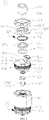
FIG. 2 is an exploded view of the atomizer shown inFIG. 1 ; -
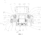
FIG. 3 is a cross-sectional view of the upper cover assembly of the atomizer shown inFIG. 2 (the liquid injection hole is in a closed state); -
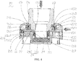
FIG. 4 is another cross-sectional view of the upper cover assembly of the atomizer shown inFIG. 2 (the mouthpiece is in a depressed state); -
FIG. 5 is another cross-sectional view of the upper cover assembly of the atomizer shown inFIG. 2 (the liquid injection hole is in an open state) -
FIG. 6 is a cross-sectional view of the atomizer shown inFIG. 1 ; - The part names and reference signs thereof in the figures are as follows:
atomizer 100liquid storage member 10upper cover assembly 20base assembly 30atomizing head 40 vent tube 11liquid storage chamber 12upper cover 21sliding cover 22retaining member 23locking member 24pushing cover 25mouthpiece 26first elastic member 27second elastic member 28vent hole 211sliding block 212sliding groove 213liquid injection hole 214blind hole 215elastic abutting member 216connecting ring 217abutting ring 218base plate 221mounting ring 222limiting ring 223through hole 2211flange 231abutting edge 2111first cavity 232locking portion 241sliding portion 242fixing ring 251positioning ring 252second cavity 253pushing ring 261abutting surface 262sliding member 29sliding block 291second sealing member 263base 31connecting member 32adjusting member 33first electrode 34mounting ring 311air adjusting hole 331connecting pipe 321isolation member 35outer sleeve 41 inner sleeve 42second electrode 43liquid guiding member 441liquid inlet portion 411liquid guiding portion 421atomizing chamber 422insulating member 36spring 2161rolling ball 2162 - The present disclosure will now be described in detail with reference to the accompanying drawings. These figures are simplified schematic diagrams, which only illustrate the basic structure of the present disclosure in a schematic manner, so they only show the structures related to the present disclosure.
- As shown in
FIG. 1 andFIG. 6 , the present disclosure provides an aerosol generating device, the aerosol generating device includes anatomizer 100 and a power supply device electrically connected with theatomizer 100. Theatomizer 100 includes aliquid storage member 10, anupper cover assembly 20 disposed at one end of theliquid storage member 10, abase assembly 30 disposed at the other end of theliquid storage member 10 opposite to theupper cover assembly 20, and an atomizing head 40 accommodated in theliquid storage member 10. In use, the aerosol-forming substrate in theliquid storage member 10 enters the atomizing head 40, the power supply device supplies power to the atomizing head 40 to atomize the aerosol-forming substrate to generate smoke for the user to inhale. - The
liquid storage member 10 is substantially in the form of a hollow cylindrical structure with openings at both ends. Theliquid storage member 10 is provided with avent tube 11. Thevent tube 11 is substantially in the form of a hollow cylindrical structure with openings at both ends. One end of thevent tube 11 is connected to theupper cover assembly 20, the other end of thevent tube 11 is connected to thebase assembly 30. Aliquid storage chamber 12 for storing the aerosol-forming substrate is formed by the inner wall of theliquid storage member 10 and the outer wall of thevent tube 11. - As shown in
FIG. 2 andFIG. 3 , theupper cover assembly 20 includes anupper cover 21, aretaining member 23 provided on theupper cover 21, a slidingcover 22 and alocking member 24 slidably provided on theupper cover 21, a pushingcover 25 provided on the slidingcover 22, amouthpiece 26 slidably provided on the pushingcover 25, a firstelastic member 27, and a secondelastic member 28. - The
upper cover 21 is substantially cylindrical, the opposite sides of theupper cover 21 are respectively provided with asliding block 212. Eachsliding block 212 is substantially L-shaped. Asliding groove 213 is formed between the twosliding blocks 212, thesliding cover 22 is slidably arranged in thesliding groove 213. Theupper cover 21 is provided with avent hole 211 along its axial direction. In this embodiment, thevent hole 211 is provided approximately at the center of theupper cover 21, thevent hole 211 is located between the twosliding blocks 212. Theupper cover 21 is provided with aliquid injection hole 214 on one side of thethrough hole 211. Theupper cover 21 is further provided with ablind hole 215, theliquid injection hole 214 and theblind hole 215 are provided on opposite sides of the throughhole 211. Theupper cover 21 is provided with asealing groove 219 around theliquid injection hole 214. Theupper cover assembly 20 further includes afirst sealing member 201 and an elastic abuttingmember 216. The elastic abuttingmember 216 includes aspring 2161 and a rolling ball 2162 provided at one end of thespring 2161. Thefirst sealing member 201 is accommodated in the sealinggroove 219 and is sealed around the outer periphery of theliquid injection hole 214. The elastic abuttingmember 216 is accommodated in theblind hole 215. - On the end surface of the
upper cover 21 away from thesliding blocks 212, a connectingring 217 and anabutting ring 218 are protruded from the inner side and the outer side respectively. The inner cavity of the connectingring 217 is communicated with thevent hole 211. When theupper cover 21 is connected to theliquid storage member 10, the abuttingring 218 is inserted into theliquid storage member 10, and the connectingring 217 is connected with one end of thevent tube 11, so that thevent hole 211 is communicated with the inner cavity of thevent tube 11, and theliquid injection hole 214 is communicated with theliquid storage chamber 12, such that the aerosol-forming substrate can be injected into theliquid storage chamber 12 through theliquid injection hole 214. In this embodiment, the connectingring 217 and thevent tube 11 are connected by a screw thread. An inner thread is provided at the inner wall of the connectingring 217. The outer wall of thevent tube 11 is provided with an external thread. It can be understood that, in other embodiments not shown, the connectingring 217 and thevent tube 11 may also be connected in a detachable manner such as snapping connection or plugging connection. Anabutting edge 2111 is protruded at the inner wall of thevent hole 211. - The sliding
cover 22 includes abase plate 221 and amounting ring 222 and a limitingring 223 arranged on thebase plate 221. Thebase plate 221 is approximately waist-shaped. Thebase plate 221 is provided with a throughhole 2211. The limitingring 223 and the mountingring 222 are protruded on thebase plate 221 from the inner side and the outer side respectively. The parts of thebase plate 221 located at opposite sides of the mountingring 222 are slidably arranged in the slidinggroove 213. Theliquid injection hole 214 can be opened or closed during the sliding process of thebase plate 221 along the slidinggroove 213. One end of thespring 2161 accommodated in theblind hole 215 elastically abuts against the bottom wall of theblind hole 215. The rolling ball 2162 connected to the other end of thespring 2161 elastically abuts against the end surface of thebase plate 221, so as to enhance the damping feeling when the slidingcover 22 slides relative to theupper cover 21 and prevent the slidingcover 22 from being pushed open too easily, thereby preventing a child from accidentally pushing the slidingcover 22 and easily opening the slidingcover 22 to cause the aerosol-forming substrate to leak. - The retaining
member 23 is roughly cylindrical with openings at both ends, one end of the retainingmember 23 is provided with aflange 231, the retainingmember 23 is inserted into thevent hole 211. One end of the retainingmember 23 away from theflange 231 abuts against the abuttingedge 2111. One end of the retainingmember 23 with theflange 231 abuts against the slidingcover 22. Afirst cavity 232 is formed between the retainingmember 23 and theabutting edge 2111. Thefirst cavity 232 is arranged along the axial direction of theupper cover 21. - The locking
member 24 includes a lockingportion 241 and a slidingportion 242 provided on the lockingportion 241. The lockingportion 241 is roughly in the shape of a hollow cylinder with openings at both ends. The slidingportion 242 is a protruding ring protruding from the outer wall of the lockingportion 241. The lockingportion 241 is slidably inserted in thevent hole 211. The slidingportion 242 is slidably received in thefirst cavity 232. One end of the lockingportion 241 extends beyond the retainingmember 23 to protrude to the outside theupper cover 21, and abuts against the inner wall of the throughhole 2211, so as to prevent the sliding of the slidingcover 22 relative to theupper cover 21. The other end of the lockingportion 241 abuts against the abuttingedge 2111. - The first
elastic member 27 is sleeved at the outside of the slidingportion 242. The upper end of the firstelastic member 27 elastically abuts against the lockingportion 241, and the lower end of the firstelastic member 27 elastically abuts against the abuttingedge 2111. - The pushing
cover 25 is roughly in the form of a hollow cylindrical structure with an opening at one end. The pushingcover 25 is provided with a fixingring 251, the fixingring 251 is roughly in the shape of a hollow cylinder with two ends being open. The upper end of the fixingring 251 extends through the top of the pushingcover 25. Apositioning ring 252 extends radially inward from the fixingring 251. The pushingcover 25 is sleeved on the slidingcover 22, the lower end of the pushingcover 25 abuts against theupper cover 21, the fixingring 251 is inserted into the mountingring 222. Asecond cavity 253 is formed between thepositioning ring 252, the fixingring 251 and the slidingcover 22. - The
mouthpiece 26 is roughly in the shape of a hollow cylinder with two ends running through. One end of themouthpiece 26 is provided with a pushingring 261. The step surface between the pushingring 261 and themouthpiece 26 forms anabutting surface 262. One end of themouthpiece 26 provided with the pushingring 261 is slidably inserted into the pushingcover 25, and the pushingring 261 abuts against one end of the lockingportion 241. - In one embodiment, a sliding
member 29 is sandwiched between the pushingcover 25 and themouthpiece 26, and a slidingblock 291 is protruded on the slidingmember 29. The slidingmember 29 is sleeved on themouthpiece 26, and the slidingblock 291 is slidably arranged in thesecond cavity 253. The secondelastic member 28 is sleeved at the outside of the slidingmember 29. One end of the secondelastic member 28 elastically abuts against the slidingcover 22, and the other end of the secondelastic member 28 elastically abuts against the slidingblock 291. - In one embodiment, in order to enhance the sealing between the sliding
member 29 and themouthpiece 26, asecond sealing member 263 is sandwiched between the slidingmember 29 and themouthpiece 26. It can be understood that thesecond sealing member 263 is made of a sealing material such as rubber or silicone. - As shown in
FIG. 1 ,FIG. 2 andFIG. 6 , thebase assembly 30 includes a base 31 connected to theliquid storage member 10, a connectingmember 32 provided on thebase 31, an adjustingmember 33 rotatably provided on the connectingmember 32, and afirst electrode 34 mounted on the connectingmember 32. - The
base 31 is roughly in the shape of a hollow cylinder with openings at both ends. One end of thebase 31 is protruded with a mountingring 311. Thebase 31 is sleeved on one end of thevent tube 11 away from theupper cover assembly 20. The connectingmember 32 is roughly in the shape of a hollow cylinder with an opening at one end. The connectingmember 32 is provided with an air inlet hole. The connectingmember 32 is sleeved on the mountingring 311. Corresponds to the air inlet hole, the adjustingmember 33 is provided with anair adjusting hole 331 communicating with the outside environment. Rotating the adjustingmember 33 can control the communication area between theair adjusting hole 331 and the air inlet hole, so as to facilitate the user to adjust the amount of air intake to meet the needs of different users. One end of the connectingmember 32 away from the open end extends downward along its axial direction to form a hollow connectingpipe 321. Thefirst electrode 34 is accommodated in the connectingpipe 321. Anisolation member 35 is provided between thefirst electrode 34 and the connectingpipe 321. Thefirst electrode 24 and the connectingpipe 321 are electrically isolated from each other by theisolation member 35. The connectingpipe 321 is detachably connected to the power supply device, when the two are connected, thefirst electrode 34 is electrically connected to one of the positive and negative electrodes of the power supply device, and the connectingpipe 321 is electrically connected to the other electrode of the positive and negative electrodes of the power supply device. - The atomizing head 40 includes an outer sleeve 41, an
inner sleeve 42 accommodated in the outer sleeve 41, asecond electrode 43 mounted on theinner sleeve 42, and a heating structure accommodated in theinner sleeve 42. - Both the outer sleeve 41 and the
inner sleeve 42 are in the shape of a hollow cylinder with openings at both ends. The outer sleeve 41 is provided with aliquid inlet portion 411. One end of the outer sleeve 41 is connected to thevent tube 11. The other end of the outer sleeve 41 is inserted into thebase 31. Theinner sleeve 42 is provided with aliquid guiding portion 421. One end of theinner sleeve 42 is connected to thevent tube 11. The other end of theinner sleeve 42 is connected to the outer sleeve 41. A gap is provided between theinner sleeve 42 and the outer sleeve 41. The space inside theinner sleeve 42 forms anatomizing chamber 422. The aerosol-forming substrate in theliquid storage chamber 12 flows into theatomizing chamber 422 through theliquid inlet portion 411 and theliquid guiding portion 421 in sequence. It can be understood that theliquid inlet portion 411 and theliquid guiding portion 421 include but are not limited to holes or grooves, so long as it is satisfied that the aerosol-forming substrate in theliquid storage chamber 12 can enter theatomizing chamber 422 through theliquid inlet portion 411 and theliquid guiding portion 421. The gap between theinner sleeve 42 and the outer sleeve 41 is used to store the aerosol-forming substrate entering from theliquid storage chamber 12 into the outer sleeve 41, to avoid that the amount of the aerosol-forming substrate entering from theliquid storage chamber 12 into theatomizing chamber 422 is too large. - The
second electrode 43 is a hollow structure, the upper end of thesecond electrode 43 is an open end so as to communicate with theatomizing chamber 422. The sidewall at the lower end of thesecond electrode 43 is provided with openings so as to communicate with the inner cavity of thebase 31, so that the external air enters theatomizing chamber 422 and mixes with the smoke. Thesecond electrode 43 is installed at one end of theinner sleeve 42 away from thevent tube 11. An insulatingmember 36 is provided between thesecond electrode 43 and theinner sleeve 42. Thesecond electrode 43 and theinner sleeve 42 are electrically isolated from each other by the insulatingmember 36. Thesecond electrode 43 is in contact with and electrically connected to thefirst electrode 34. - The heating structure includes a
liquid guiding member 441 and a heating member in contact with each other. Theliquid guiding member 441 is used for absorbing the aerosol-forming substrate that flows from theliquid storage chamber 12 to theatomizing chamber 422 via theliquid inlet portion 411 and theliquid guiding portion 421. The heating member is used to heat the aerosol-forming substrate in theliquid guiding member 441. One end of the heating member is electrically connected to one of the positive and negative electrodes of the power supply device through thesecond electrode 43 and thefirst electrode 34. The other end of the heating member is electrically connected to the other electrode of the positive and negative electrodes of the power supply device through theinner sleeve 42, thebase 31 and the connectingmember 32. Thus, the heating member heats the aerosol-forming substrate in theliquid guiding member 441 under the electric driving of the power supply device to generate smoke, the external air enters theatomizing chamber 422 through theair adjusting hole 331 and the air inlet hole to mix with the smoke, the mixed gas enters the user's mouth through the inner cavity of thevent tube 11, the inner cavity of the lockingmember 24 and the inner cavity of themouthpiece 26 in sequence for the user to inhale. In this embodiment, theliquid guiding member 441 is cotton, the heating member is a heating mesh. It can be understood that, in other embodiments not shown, theliquid guiding member 441 can also be porous ceramics, fiber ropes, foamed metal or foamed graphite. The heating member can also be a heating wire or a heating orifice plate. - As shown in
FIGs. 4 to 6 , when the aerosol-forming substrate in theliquid storage chamber 12 is insufficient and needs to perform liquid injection, themouthpiece 26 is depressed downwards along the axial direction of themouthpiece 26, the slidingblock 291 slides down along thesecond cavity 253 to overcome the elastic force of the secondelastic member 28 so that the secondelastic member 28 is compressed, the pushingring 261 slides downward and pushes the lockingportion 241 of the lockingmember 24 to slide downward, so that the slidingportion 242 slides in thefirst cavity 232 and the firstelastic member 27 is compressed. When theabutting surface 262 of themouthpiece 26 abuts against the slidingcover 22 and/or the slidingmember 29 abuts against the limitingring 223, the lockingmember 24 slides into theupper cover 21, and the pushingring 261 abuts against the retainingmember 23. At this time, the pushingcover 25 is pushed along the radial direction of the pushingcover 25, the pushingcover 25 drives the slidingcover 22 to slide relative to theupper cover 21 along the slidinggroove 213, thereby opening theliquid injection hole 214 for performing liquid injection. At this time, when the slidingcover 22 is released, under the elastic force of the secondelastic member 28, the slidingmember 29 drives themouthpiece 26 to slide and reset along thesecond cavity 253. Due to the elastic force of the secondelastic member 28, the slidingmember 29 tightly abuts against the pushingcover 25 to enhance the sealing between the slidingmember 29 and the pushingcover 25, so as to prevent the smoke from being emitted through the gap between the slidingmember 29 and the pushingcover 25 when the user sucks the aerosol generating device. - After the liquid injection is completed, the pushing
cover 25 is pushed in the opposite direction, the pushingcover 25 drives the slidingcover 22 to slide relative to theupper cover 21 until the slidingcover 22 moves above theliquid injection hole 214 and theliquid injection hole 214 is closed. At the same time, the lockingmember 24 slides and resets along thefirst cavity 232 under the elastic force of the firstelastic member 27, so that the lockingmember 24 abuts against the slidingcover 22, thereby limiting the sliding of the pushingcover 25 and preventing the pushingcover 25 from being pushed forcefully to cause the pushingcover 25 to be misaligned with theupper cover 21. - It is understood that in other embodiments not shown, the sliding
member 29 may be omitted. One end of the secondelastic member 28 elastically abuts against the slidingcover 22, the other end of the secondelastic member 28 elastically abuts against themouthpiece 26, so long as it is satisfied that the elastic force of the secondelastic member 28 is overcome when sliding themouthpiece 26 to prevent children from sliding easily, and further after releasing themouthpiece 26, themouthpiece 26 can be reset under the elastic restoring force of the secondelastic member 28. It can be understood that in other unshown embodiments, both the slidingmember 29 and the secondelastic member 28 can be omitted, in this case, after themouthpiece 26 is pressed down, themouthpiece 26 can reset under the pushing of the lockingmember 24. - It can be understood that in other embodiments not shown, the pushing
cover 25 and the slidingcover 22 are integrally formed, and in this case, themouthpiece 26 is slidably arranged on the slidingcover 22. - It can be understood that in other embodiments not shown, the retaining
member 23 may be omitted, and it is only required that the lockingmember 24 is slidably arranged at theupper cover 21. - In the
atomizer 100 provided by the present disclosure, by slidably arranging the slidingcover 22 and the lockingmember 24 on theupper cover 21, one end of the lockingmember 24 abuts against the slidingcover 22 to prevent the slidingcover 22 from sliding relative to theupper cover 21. Further, amouthpiece 26 that can slide relative to the slidingcover 22 is provided, themouthpiece 26 abuts against the lockingmember 24, sliding themouthpiece 26 can drive the lockingmember 24 to move so as to release the abutment to the slidingcover 22, so that the slidingcover 22 can slide relative to theupper cover 21 to open or close theliquid injection hole 214, thereby preventing children from easily opening theatomizer 100 to contact the aerosol-forming substrate and thus improving the safety of theatomizer 100. - The aerosol generating device provided by the present invention has the same technical effects as the above-mentioned
atomizer 100 because it has all the technical features of the above-mentionedatomizer 100. - Taking the above-mentioned ideal embodiments according to the present disclosure as enlightenment, through the above description, the relevant persons can make various changes and modifications without departing from the concept of the present disclosure. The technical scope of the present disclosure is not limited to the content of the specification, and its technical scope should be determined according to the scope of the claims.
Claims (10)
- An upper cover assembly comprising an upper cover, a mouthpiece and a sliding cover slidably provided on the upper cover, wherein the upper cover is provided with a liquid injection hole, and the upper cover is provided with a first cavity, the upper cover assembly further comprises a locking member slidably arranged in the first cavity, a first elastic member is sleeved on the locking member, one end of the locking member abuts against the sliding cover to prevent the sliding cover from sliding relative to the upper cover, the mouthpiece is slidable relative to the sliding cover, and the mouthpiece abuts against the locking member; by sliding the mouthpiece to cause the locking member to compress the first elastic member and slide in the first cavity until the sliding cover is released, the sliding cover can slide relative to the upper cover to open or close the liquid injection hole.
- The upper cover assembly of claim 1, wherein the locking member comprises a locking portion and a sliding portion provided on the locking portion, the sliding portion is slidably arranged in the first cavity, the first elastic member is sleeved at the outside of the locking portion; when the locking member slides in the first cavity under an external force, the locking member compresses the first elastic member and when the locking member is released, the locking member is reset under an elastic force of the first elastic member and abuts against the sliding cover again.
- The upper cover assembly of claim 1, wherein the upper cover assembly further comprises a retaining member, the upper cover is provided with a vent hole along its axial direction, an abutting edge is provided at an inner wall of the vent hole, the retaining member is located in the vent hole, the first cavity is formed by the retaining member and the abutting edge, one end of the first elastic member elastically abuts against the retaining member, the other end of the first elastic member elastically abuts against the abutting edge.
- The upper cover assembly of claim 1, wherein the upper cover assembly further comprises a pushing cover, the pushing cover is sleeved on the sliding cover, the mouthpiece is slidably provided on the pushing cover.
- The upper cover assembly of claim 4, wherein a sliding member is provided between the pushing cover and the mouthpiece, the pushing cover is provided with a second cavity, the sliding member is slidably arranged in the second cavity, the upper cover assembly further comprises a second elastic member, the second elastic member is sleeved at the outside of the sliding member; when the sliding member slides in the second cavity under an external force, the sliding member compresses the second elastic member, and when the external force is removed, the sliding member is reset under an elastic force of the second elastic member.
- The upper cover assembly of claim 5, wherein a mounting ring is provided on the upper cover, the pushing cover is provided with a fixing ring, the fixing ring is inserted into the mounting ring, a positioning ring extends radially inward from the fixing ring, the second cavity is formed by the positioning ring, the fixing ring and the sliding cover.
- The upper cover assembly of claim 5, wherein a limiting ring is further provided on the sliding cover, when the sliding member slides in the second cavity under an external force until the sliding member abuts against the limiting ring, the locking member releases the sliding cover.
- The upper cover assembly of claim 1, wherein a pushing ring is provided at one end of the mouthpiece, a step surface between the pushing ring and the mouthpiece forms an abutting surface, the pushing ring abuts against one end of the locking member; by sliding the mouthpiece to cause the pushing ring pushes the locking member to slide until the abutting surface abuts against the sliding cover, the locking member is located in the upper cover.
- An atomizer comprising the upper cover assembly according to any one of claims 1 to 8.
- An aerosol generating device comprising the atomizer of claim 9.
Applications Claiming Priority (2)
| Application Number | Priority Date | Filing Date | Title |
|---|---|---|---|
| CN202020204438.2U CN211746942U (en) | 2020-02-24 | 2020-02-24 | Cover assembly, atomizer and aerosol generating device |
| PCT/CN2021/071990 WO2021169656A1 (en) | 2020-02-24 | 2021-01-15 | Upper cover assembly, and atomizer and aerosol generating device therefor |
Publications (2)
| Publication Number | Publication Date |
|---|---|
| EP4111894A1 true EP4111894A1 (en) | 2023-01-04 |
| EP4111894A4 EP4111894A4 (en) | 2024-04-24 |
Family
ID=72909424
Family Applications (1)
| Application Number | Title | Priority Date | Filing Date |
|---|---|---|---|
| EP21759751.7A Withdrawn EP4111894A4 (en) | 2020-02-24 | 2021-01-15 | TOP COVER ASSEMBLY, ATOMIZER AND AEROSOL GENERATING DEVICE THEREFOR |
Country Status (3)
| Country | Link |
|---|---|
| EP (1) | EP4111894A4 (en) |
| CN (1) | CN211746942U (en) |
| WO (1) | WO2021169656A1 (en) |
Cited By (1)
| Publication number | Priority date | Publication date | Assignee | Title |
|---|---|---|---|---|
| WO2024215707A1 (en) * | 2023-04-11 | 2024-10-17 | Puff Corporation | Carb cap for vaporization assembly, portable vaporization device, and methods of use |
Families Citing this family (4)
| Publication number | Priority date | Publication date | Assignee | Title |
|---|---|---|---|---|
| CN211746942U (en) * | 2020-02-24 | 2020-10-27 | 常州市派腾电子技术服务有限公司 | Cover assembly, atomizer and aerosol generating device |
| CN114027606B (en) * | 2021-12-16 | 2024-02-06 | 苏州小枣树网络科技有限公司 | Handheld hair dryer |
| CN114766732A (en) * | 2022-05-05 | 2022-07-22 | 杨军宏 | Electronic cigarette |
| CN115300728B (en) * | 2022-08-09 | 2023-08-08 | 宁波赛嘉电器有限公司 | Sprayers with leak-proof pistons |
Family Cites Families (6)
| Publication number | Priority date | Publication date | Assignee | Title |
|---|---|---|---|---|
| CN204796749U (en) * | 2015-06-19 | 2015-11-25 | 卓尔悦(常州)电子科技有限公司 | Atomizer and aerosol generating device thereof |
| CN205284996U (en) * | 2015-12-09 | 2016-06-08 | 李述亨 | Sliding closure formula electron smog spinning disk atomiser |
| EP3560358A4 (en) * | 2016-12-21 | 2020-07-08 | Changzhou Patent Electronic Technology Co., Ltd | Liquid injection protection device, atomizer and electronic cigarette |
| CN109077362A (en) * | 2018-09-28 | 2018-12-25 | 广东思格雷电子科技股份有限公司 | Atomizer with child lock |
| CN209883061U (en) * | 2019-01-28 | 2020-01-03 | 常州市派腾电子技术服务有限公司 | Atomizers and Electronic Cigarettes |
| CN211746942U (en) * | 2020-02-24 | 2020-10-27 | 常州市派腾电子技术服务有限公司 | Cover assembly, atomizer and aerosol generating device |
-
2020
- 2020-02-24 CN CN202020204438.2U patent/CN211746942U/en not_active Expired - Fee Related
-
2021
- 2021-01-15 WO PCT/CN2021/071990 patent/WO2021169656A1/en not_active Ceased
- 2021-01-15 EP EP21759751.7A patent/EP4111894A4/en not_active Withdrawn
Cited By (1)
| Publication number | Priority date | Publication date | Assignee | Title |
|---|---|---|---|---|
| WO2024215707A1 (en) * | 2023-04-11 | 2024-10-17 | Puff Corporation | Carb cap for vaporization assembly, portable vaporization device, and methods of use |
Also Published As
| Publication number | Publication date |
|---|---|
| CN211746942U (en) | 2020-10-27 |
| WO2021169656A1 (en) | 2021-09-02 |
| EP4111894A4 (en) | 2024-04-24 |
Similar Documents
| Publication | Publication Date | Title |
|---|---|---|
| US11871794B2 (en) | Atomizer of electronic cigarette providing child protection function | |
| CN211672451U (en) | Atomizer and aerosol generating device | |
| CN211746942U (en) | Cover assembly, atomizer and aerosol generating device | |
| EP3824750B1 (en) | Electronic cigarette | |
| CN206687160U (en) | Atomizer and its electronic cigarette | |
| CN108065452B (en) | A kind of atomizer and electronic cigarette thereof | |
| EP3549459A1 (en) | Cartridge and atomizer thereof, and electronic cigarette | |
| CN212164889U (en) | Atomizer and aerosol generating device | |
| US20190335814A1 (en) | Cigarette cartridge, atomizer and electronic cigarette thereof | |
| CN109588040B (en) | Liquid injection protection devices, atomizers and electronic cigarettes | |
| CN108323814A (en) | Liquid storage component, atomizer and electronic cigarette | |
| CN206413756U (en) | Liquid storage component, atomizer and its electronic cigarette | |
| CN108323812A (en) | Liquid storage component, atomizer and electronic cigarette | |
| CN209807140U (en) | e-cigarette | |
| WO2023029642A1 (en) | Atomization assembly and atomization apparatus | |
| CN210017884U (en) | Upper cover subassembly, atomizer and electron cigarette thereof | |
| EP4085772A1 (en) | Atomizer, and aerosol generation device | |
| CN206659106U (en) | Liquid storage component, atomizer and electronic cigarette | |
| CN209660456U (en) | Smoke grenade and electronic cigarette | |
| CN209518266U (en) | Smoke grenade and electronic cigarette | |
| CN209883061U (en) | Atomizers and Electronic Cigarettes | |
| EP4091466B1 (en) | Liquid injection structure, atomizer and aerosol generation device thereof | |
| CN216651326U (en) | Electronic atomization device and atomizer and atomization assembly thereof | |
| CN206413753U (en) | Liquid storage component, atomizer and electronic cigarette | |
| EP3981264B1 (en) | E-liquid storage assembly, cartridge and electronic cigarette thereof |
Legal Events
| Date | Code | Title | Description |
|---|---|---|---|
| STAA | Information on the status of an ep patent application or granted ep patent |
Free format text: STATUS: THE INTERNATIONAL PUBLICATION HAS BEEN MADE |
|
| PUAI | Public reference made under article 153(3) epc to a published international application that has entered the european phase |
Free format text: ORIGINAL CODE: 0009012 |
|
| STAA | Information on the status of an ep patent application or granted ep patent |
Free format text: STATUS: REQUEST FOR EXAMINATION WAS MADE |
|
| 17P | Request for examination filed |
Effective date: 20220825 |
|
| AK | Designated contracting states |
Kind code of ref document: A1 Designated state(s): AL AT BE BG CH CY CZ DE DK EE ES FI FR GB GR HR HU IE IS IT LI LT LU LV MC MK MT NL NO PL PT RO RS SE SI SK SM TR |
|
| DAV | Request for validation of the european patent (deleted) | ||
| DAX | Request for extension of the european patent (deleted) | ||
| REG | Reference to a national code |
Ref country code: DE Ref legal event code: R079 Free format text: PREVIOUS MAIN CLASS: A24F0047000000 Ipc: A24F0040490000 |
|
| A4 | Supplementary search report drawn up and despatched |
Effective date: 20240321 |
|
| RIC1 | Information provided on ipc code assigned before grant |
Ipc: A24F 40/40 20200101ALN20240315BHEP Ipc: A24F 40/10 20200101ALN20240315BHEP Ipc: A24F 40/49 20200101AFI20240315BHEP |
|
| STAA | Information on the status of an ep patent application or granted ep patent |
Free format text: STATUS: THE APPLICATION IS DEEMED TO BE WITHDRAWN |
|
| 18D | Application deemed to be withdrawn |
Effective date: 20241010 |