EP4110189B1 - Ineinandergreifende komponenten für intraluminale ultraschallbildgebung - Google Patents
Ineinandergreifende komponenten für intraluminale ultraschallbildgebung Download PDFInfo
- Publication number
- EP4110189B1 EP4110189B1 EP21708164.5A EP21708164A EP4110189B1 EP 4110189 B1 EP4110189 B1 EP 4110189B1 EP 21708164 A EP21708164 A EP 21708164A EP 4110189 B1 EP4110189 B1 EP 4110189B1
- Authority
- EP
- European Patent Office
- Prior art keywords
- support member
- tip member
- imaging device
- stand
- tip
- Prior art date
- Legal status (The legal status is an assumption and is not a legal conclusion. Google has not performed a legal analysis and makes no representation as to the accuracy of the status listed.)
- Active
Links
Images


Classifications
-
- A—HUMAN NECESSITIES
- A61—MEDICAL OR VETERINARY SCIENCE; HYGIENE
- A61B—DIAGNOSIS; SURGERY; IDENTIFICATION
- A61B8/00—Diagnosis using ultrasonic, sonic or infrasonic waves
- A61B8/08—Clinical applications
- A61B8/0891—Clinical applications for diagnosis of blood vessels
-
- A—HUMAN NECESSITIES
- A61—MEDICAL OR VETERINARY SCIENCE; HYGIENE
- A61B—DIAGNOSIS; SURGERY; IDENTIFICATION
- A61B8/00—Diagnosis using ultrasonic, sonic or infrasonic waves
- A61B8/12—Diagnosis using ultrasonic, sonic or infrasonic waves in body cavities or body tracts, e.g. by using catheters
-
- A—HUMAN NECESSITIES
- A61—MEDICAL OR VETERINARY SCIENCE; HYGIENE
- A61B—DIAGNOSIS; SURGERY; IDENTIFICATION
- A61B8/00—Diagnosis using ultrasonic, sonic or infrasonic waves
- A61B8/44—Constructional features of the ultrasonic, sonic or infrasonic diagnostic device
- A61B8/4444—Constructional features of the ultrasonic, sonic or infrasonic diagnostic device related to the probe
- A61B8/445—Details of catheter construction
-
- A—HUMAN NECESSITIES
- A61—MEDICAL OR VETERINARY SCIENCE; HYGIENE
- A61B—DIAGNOSIS; SURGERY; IDENTIFICATION
- A61B8/00—Diagnosis using ultrasonic, sonic or infrasonic waves
- A61B8/44—Constructional features of the ultrasonic, sonic or infrasonic diagnostic device
- A61B8/4483—Constructional features of the ultrasonic, sonic or infrasonic diagnostic device characterised by features of the ultrasound transducer
- A61B8/4488—Constructional features of the ultrasonic, sonic or infrasonic diagnostic device characterised by features of the ultrasound transducer the transducer being a phased array
-
- A—HUMAN NECESSITIES
- A61—MEDICAL OR VETERINARY SCIENCE; HYGIENE
- A61B—DIAGNOSIS; SURGERY; IDENTIFICATION
- A61B2562/00—Details of sensors; Constructional details of sensor housings or probes; Accessories for sensors
- A61B2562/16—Details of sensor housings or probes; Details of structural supports for sensors
- A61B2562/164—Details of sensor housings or probes; Details of structural supports for sensors the sensor is mounted in or on a conformable substrate or carrier
-
- A—HUMAN NECESSITIES
- A61—MEDICAL OR VETERINARY SCIENCE; HYGIENE
- A61B—DIAGNOSIS; SURGERY; IDENTIFICATION
- A61B8/00—Diagnosis using ultrasonic, sonic or infrasonic waves
- A61B8/06—Measuring blood flow
Definitions
- the present disclosure relates generally to intraluminal medical imaging, such as intravascular ultrasound (IVUS) imaging.
- IVUS intravascular ultrasound
- projections and recesses can be provided on different components forming the distal structure of an intraluminal imaging device, such as an IVUS catheter, to increase the tensile strength of the connection between these components.
- Intravascular ultrasound (IVUS) imaging is widely used in interventional cardiology as a diagnostic tool for assessing a diseased vessel, such as an artery, within the human body to determine the need for treatment, to guide the intervention, and/or to assess its effectiveness.
- An IVUS device including one or more ultrasound transducers is passed into the vessel and guided to the area to be imaged.
- the transducers emit ultrasonic energy in order to create an image of the vessel of interest.
- Ultrasonic waves are partially reflected by discontinuities arising from tissue structures (such as the various layers of the vessel wall), red blood cells, and other features of interest. Echoes from the reflected waves are received by the transducer and passed along to an IVUS imaging system.
- the imaging system processes the received ultrasound echoes to produce a cross-sectional image of the vessel where the device is placed.
- Solid-state (also known as synthetic-aperture) IVUS catheters are one of the two types of IVUS devices commonly used today, the other type being the rotational IVUS catheter.
- Solid-state IVUS catheters carry a scanner assembly that includes an array of ultrasound transducers distributed around its circumference along with one or more integrated circuit controller chips mounted adjacent to the transducer array. The controllers select individual acoustic elements (or groups of elements) for transmitting an ultrasound pulse and for receiving the ultrasound echo signal. By stepping through a sequence of transmit-receive pairs, the solid-state IVUS system can synthesize the effect of a mechanically scanned ultrasound transducer but without moving parts (hence the solid-state designation).
- the transducer array can be placed in direct contact with the blood and vessel tissue with minimal risk of vessel trauma. Furthermore, because there is no rotating element, the electrical interface is simplified.
- the solid-state scanner can be wired directly to the imaging system with a simple electrical cable and a standard detachable electrical connector, rather than the complex rotating electrical interface required for a rotational IVUS device.
- IVUS devices sufficiently narrow to traverse anatomic structures within the human vasculature is challenging and two general performance standards must be met.
- IVUS devices must be extremely narrow to successfully pass through the small lumens in the human body without damaging tissue and
- intraluminal imaging devices must have high tensile strength to ensure that the device or parts of the device do not separate during a procedure. Such a breakage may cause parts of an intraluminal imaging device to be left within the heart or vasculature creating a condition that is extremely difficult to remedy.
- connections between various components of intraluminal imaging devices exhibit weaker tensile strength than unitary structures and are therefore more prone to separation.
- WO 2019/115568 A1 discloses an intraluminal imaging device comprising a flexible elongate member configured to be inserted into a body lumen of a patient, an ultrasound imaging assembly disposed at the distal portion of the flexible elongate member.
- the imaging assembly comprises a support member, a flexible substrate positioned around the support member, a plurality of ultrasound transducer elements integrated in the flexible substrate, and a plurality of control circuits disposed on the flexible substrate at a position proximal to the plurality of transducer elements.
- a distal member is coupled to the distal portion of the support member.
- the flexible substrate, the support member, the distal member, a proximal inner member, and/or a proximal outer member are coupled to one another via an adhesive.
- WO 2017/168300 A1 discloses an intraluminal imaging device comprising a flexible elongate member configured to be inserted into a lumen of a patient, an ultrasound imaging assembly disposed at the distal portion of the a flexible elongate member and configured to obtain ultrasound imaging data while positioned within the lumen of the patient, a tip member disposed at the distal portion of the flexible elongate member, the tip member comprising a cavity adjacent to the ultrasound imaging assembly and configured to be filled with an adhesive to couple the tip member and the ultrasound imaging assembly.
- Embodiments of the present disclosure are intraluminal imaging devices, such as intravascular ultrasound (IVUS) catheters.
- IVUS catheter described herein provides stronger attachment between components at the distal end, which overcome the limitations described above.
- an ultrasound imaging assembly is coupled to a proximal end of the tip member.
- the imaging assembly is formed of a polymer support member and a flexible substrate positioned around the support member.
- the distal end of the support member includes one or more recesses.
- a proximal end of the tip member includes one or more protrusions extending inwardly into the inner lumen created by the tip member. These proximal protrusions received into the corresponding recesses of the support member.
- the ultrasound imaging assembly comprises a support member and a flexible substrate positioned around the support member, and the support member comprises the recess.
- the support member comprises a proximal portion and a distal portion, wherein the recess is disposed at the distal portion of the support member, the tip member comprises a proximal portion and a distal portion, the protrusion is disposed at the proximal portion of the tip member, and the distal portion of the support member is coupled to the proximal portion of the tip member.
- the flexible elongate member comprises an inner member extending through the support member such that the recess exposes a portion of the inner member.
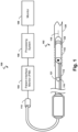
- Fig. 1 is a diagrammatic schematic view of an intraluminal imaging system 100.
- the intraluminal imaging system 100 can be an ultrasound imaging system.
- the system 100 can be an intravascular ultrasound (IVUS) imaging system.
- the system 100 may include an intraluminal imaging device 102 such as a catheter, guide wire, or guide catheter, a patient interface module (PIM) 104, a processing system or console 106, and a monitor 108.
- the intraluminal imaging device 102 can be an ultrasound imaging device.
- the device 102 can be an IVUS imaging device, such as a solid-state IVUS device.
- the PIM 104 facilitates communication of signals between the IVUS console 106 and the scanner assembly 110 included in the IVUS device 102.
- This communication includes the steps of: (1) providing commands to integrated circuit controller chip(s) 206A and 206B, illustrated in Fig. 2 , included in the scanner assembly 110 to select the particular transducer array element(s), or acoustic element(s), to be used for transmit and receive, (2) providing the transmit trigger signals to the integrated circuit controller chip(s) 206A and 206B included in the scanner assembly 110 to activate the transmitter circuitry to generate an electrical pulse to excite the selected transducer array element(s), and/or (3) accepting amplified echo signals received from the selected transducer array element(s) via amplifiers included on the integrated circuit controller chip(s)126 of the scanner assembly 110.
- the PIM 104 performs preliminary processing of the echo data prior to relaying the data to the console 106. In examples of such embodiments, the PIM 104 performs amplification, filtering, and/or aggregating of the data. In an embodiment, the PIM 104 also supplies high- and low-voltage DC power to support operation of the device 102 including circuitry within the scanner assembly 110.
- the IVUS console 106 receives the echo data from the scanner assembly 110 by way of the PIM 104 and processes the data to reconstruct an image of the tissue structures in the medium surrounding the scanner assembly 110.
- the console 106 outputs image data such that an image of the vessel 120, such as a cross-sectional image of the vessel 120, is displayed on the monitor 108.
- Vessel 120 may represent fluid filled or surrounded structures, both natural and man-made.
- the vessel 120 may be within a body of a patient.
- the vessel 120 may be a blood vessel, as an artery or a vein of a patient's vascular system, including cardiac vasculature, peripheral vasculature, neural vasculature, renal vasculature, and/or or any other suitable lumen inside the body.
- the IVUS device includes some features similar to traditional solid-state IVUS catheters, such as the EagleEye ® catheter available from Volcano Corporation and those disclosed in U.S. Patent No. 7,846,101 .
- the IVUS device 102 includes the scanner assembly 110 near a distal end of the device 102 and a transmission line bundle 112 extending along the longitudinal body of the device 102.
- the transmission line bundle or cable 112 can include a plurality of conductors, including one, two, three, four, five, six, seven, or more conductors 218 ( Fig. 2 ). It is understood that any suitable gauge wire can be used for the conductors 218.
- the transmission line bundle 112 terminates in a PIM connector 114 at a proximal end of the device 102.
- the PIM connector 114 electrically couples the transmission line bundle 112 to the PIM 104 and physically couples the IVUS device 102 to the PIM 104.
- the IVUS device 102 further includes a guide wire exit port 116. Accordingly, in some instances the IVUS device is a rapid-exchange catheter.
- the guide wire exit port 116 allows a guide wire 118 to be inserted towards the distal end in order to direct the device 102 through the vessel 120.
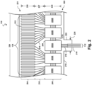
- the flexible substrate 214 on which the transducer control logic dies 206 and the transducers 212 are mounted, provides structural support and interconnects for electrical coupling.
- the flexible substrate 214 may be constructed to include a film layer of a flexible polyimide material such as KAPTON TM (trademark of DuPont).
- a flexible polyimide material such as KAPTON TM (trademark of DuPont).
- suitable materials include polyester films, polyimide films, polyethylene napthalate films, or polyetherimide films, liquid crystal polymer, other flexible printed semiconductor substrates as well as products such as Upilex ® (registered trademark of Ube Industries) and TEFLON ® (registered trademark of E.I. du Pont).
- Upilex ® registered trademark of Ube Industries
- TEFLON ® registered trademark of E.I. du Pont
- the flexible substrate 214 is configured to be wrapped around a support member 230 ( Fig. 3 ) in some instances. Therefore, the thickness of the film layer of the flexible substrate 214 is generally related to the degree of curvature in the final assembled flexible assembly 110. In some embodiments, the film layer is between 5 ⁇ m and 100 ⁇ m, with some particular embodiments being between 5 ⁇ m and 25.1 ⁇ m, e.g., 6 ⁇ m.
- the set of transducer control logic dies 206 is a non-limiting example of a control circuit.
- the transducer region 204 is disposed at a distal portion 221 of the flexible substrate 214.
- the control region 208 is disposed at a proximal portion 222 of the flexible substrate 214.
- the transition region 210 is disposed between the control region 208 and the transducer region 204. Dimensions of the transducer region 204, the control region 208, and the transition region 210 (e.g., lengths 225, 227, 229) can vary in different embodiments.
- the lengths 225, 227, 229 can be substantially similar or, the length 227 of the transition region 210 may be less than lengths 225 and 229, the length 227 of the transition region 210 can be greater than lengths 225, 229 of the transducer region and controller region, respectively.
- the control logic dies 206 are not necessarily homogenous.
- a single controller is designated a master control logic die 206A and contains the communication interface for cable 112, between a processing system, e.g., processing system 106, and the flexible assembly 110.
- the master control circuit may include control logic that decodes control signals received over the cable 112, transmits control responses over the cable 112, amplifies echo signals, and/or transmits the echo signals over the cable 112.
- the remaining controllers are slave controllers 206B.
- the slave controllers 206B may include control logic that drives a transducer 212 to emit an ultrasonic signal and selects a transducer 212 to receive an echo.
- Suitable materials for the conductive traces 216 include copper, gold, aluminum, silver, tantalum, nickel, and tin, and may be deposited on the flexible substrate 214 by processes such as sputtering, plating, and etching.
- the flexible substrate 214 includes a chromium adhesion layer.
- the width and thickness of the conductive traces 216 are selected to provide proper conductivity and resilience when the flexible substrate 214 is rolled. In that regard, an exemplary range for the thickness of a conductive trace 216 and/or conductive pad is between 1-5 ⁇ m. For example, in an embodiment, 5 ⁇ m conductive traces 216 are separated by 5 ⁇ m of space.
- the width of a conductive trace 216 on the flexible substrate may be further determined by the width of the conductor 218 to be coupled to the trace/pad.
- the conductor interface 220 is positioned at other parts of the flexible substrate 214, such as the distal portion 221, or the flexible substrate 214 may lack the conductor interface 220.
- the substrate forming the conductor interface 220 is made of the same material(s) and/or is similarly flexible as the flexible substrate 214. In other embodiments, the conductor interface 220 is made of different materials and/or is comparatively more rigid than the flexible substrate 214.
- the conductor interface 220 can be made of a plastic, thermoplastic, polymer, hard polymer, etc., including polyoxymethylene (e.g., DELRIN ® ), polyether ether ketone (PEEK), nylon, Liquid Crystal Polymer (LCP), and/or other suitable materials.
- polyoxymethylene e.g., DELRIN ®
- PEEK polyether ether ketone
- nylon e.g., polyether ether ketone
- LCP Liquid Crystal Polymer
- Fig. 3 illustrates a perspective view of the scanner assembly 110 in a rolled configuration.
- the flexible substrate 214 is transitioned from a flat configuration ( Fig. 2 ) to a rolled or more cylindrical configuration ( Fig. 3 ).
- techniques are utilized as disclosed in one or more of U.S. Patent No. 6,776,763 , titled “ULTRASONIC TRANSDUCER ARRAY AND METHOD OF MANUFACTURING THE SAME" and U.S. Patent No. 7,226,417 , titled “HIGH RESOLUTION INTRAVASCULAR ULTRASOUND SENSING ASSEMBLY HAVING A FLEXIBLE SUBSTRATE”.
- the transducer elements 212 and/or the controllers 206 can be positioned in an annular configuration, such as a circular configuration or in a polygon configuration, around a longitudinal axis 250 of a support member 230.
- the longitudinal axis 250 of the support member 230 may also be referred to as the longitudinal axis of the scanner assembly 110, the flexible elongate member 121, and/or the device 102.
- a cross-sectional profile of the imaging assembly 110 at the transducer elements 212 and/or the controllers 206 can be a circle or a polygon.
- any suitable annular polygon shape can be implemented, such as one based on the number of controllers/transducers, flexibility of the controllers/transducers, etc., including a pentagon, hexagon, heptagon, octagon, nonagon, decagon, etc.
- the plurality of transducer controllers 206 may be used for controlling the plurality of ultrasound transducer elements 212 to obtain imaging data associated with the vessel 120.
- the support member 230 can be referenced as a unibody in some instances.
- the support member 230 can be composed of a metallic material, such as stainless steel, or a non-metallic material, such as a plastic or polymer as described in U.S. Provisional Application No. 61/985,220, "Pre-Doped Solid Substrate for Intravascular Devices," filed April 28, 2014 , ('220 Application).
- support member 230 may be composed of 303 stainless steel.
- the support member 230 can be a ferrule having a distal flange or portion 232 and a proximal flange or portion 234.
- the support member 230 can be tubular in shape and define a lumen 236 extending longitudinally therethrough.
- the lumen 236 can be sized and shaped to receive the guide wire 118.
- the support member 230 can be manufactured using any suitable process.
- the support member 230 can be machined and/or electrochemically machined or laser milled, such as by removing material from a blank to shape the support member 230, or molded, such as by an injection molding process.
- Fig. 4 shown there is a diagrammatic cross-sectional side view of a distal portion of the intraluminal imaging device 102, including the flexible substrate 214 and the support member 230.
- the support member 230 can be referenced as a unibody in some instances.
- the support member 230 can be composed of a metallic material, such as stainless steel, or a non-metallic material, such as a plastic or polymer as described in U.S. Provisional Application No. 61/985,220, "Pre-Doped Solid Substrate for Intravascular Devices," filed April 28, 2014 .
- the support member 230 can be ferrule having a distal portion 262 and a proximal portion 264.
- the support member 230 can define a lumen 236 extending along the longitudinal axis LA.
- the lumen 236 is in communication with the entry/exit port 116 and is sized and shaped to receive the guide wire 118 ( Fig. 1 ).
- the support member 230 can be manufactured according to any suitable process.
- the support member 230 can be machined and/or electrochemically machined or laser milled, such as by removing material from a blank to shape the support member 230, or molded, such as by an injection molding process.
- the support member 230 may be integrally formed as a unitary structure, while in other embodiments the support member 230 may be formed of different components, such as a ferrule and stands 242, 244, that are fixedly coupled to one another.
- the support member 230 and/or one or more components thereof may be completely integrated with inner member 256.
- the inner member 256 and the support member 230 may be joined as one, e.g., in the case of a polymer support member.
- Stands 242, 244 that extend vertically are provided at the distal and proximal portions 262, 264, respectively, of the support member 230.
- the stands 242, 244 elevate and support the distal and proximal portions of the flexible substrate 214.
- portions of the flexible substrate 214 such as the transducer portion 204 (or transducer region 204), can be spaced from a central body portion of the support member 230 extending between the stands 242, 244.
- the stands 242, 244 can have the same outer diameter or different outer diameters.
- the distal stand 242 can have a larger or smaller outer diameter than the proximal stand 244 and can also have special features for rotational alignment as well as control chip placement and connection.
- any cavities between the flexible substrate 214 and the surface of the support member 230 are filled with a backing material 246.
- the liquid backing material 246 can be introduced between the flexible substrate 214 and the support member 230 via passageways 235 in the stands 242, 244, or through additional recesses as will be discussed in more detail hereafter.
- suction can be applied via the passageways 235 of one of the stands 242, 244, while the liquid backing material 246 is fed between the flexible substrate 214 and the support member 230 via the passageways 235 of the other of the stands 242, 244.
- the backing material can be cured to allow it to solidify and set.
- the support member 230 includes more than two stands 242, 244, only one of the stands 242, 244, or neither of the stands.
- the support member 230 can have an increased diameter distal portion 262 and/or increased diameter proximal portion 264 that is sized and shaped to elevate and support the distal and/or proximal portions of the flexible substrate 214.
- the support member 230 can be substantially cylindrical in some embodiments. Other shapes of the support member 230 are also contemplated including geometrical, non-geometrical, symmetrical, non-symmetrical, cross-sectional profiles. As the term is used herein, the shape of the support member 230 may reference a cross-sectional profile of the support member 230. Different portions of the support member 230 can be variously shaped in other embodiments. For example, the proximal portion 264 can have a larger outer diameter than the outer diameters of the distal portion 262 or a central portion extending between the distal and proximal portions 262, 264.
- an inner diameter of the support member 230 (e.g., the diameter of the lumen 236) can correspondingly increase or decrease as the outer diameter changes. In other embodiments, the inner diameter of the support member 230 remains the same despite variations in the outer diameter.
- a proximal inner member 256 and a proximal outer member 254 are coupled to the proximal portion 264 of the support member 230.
- the proximal inner member 256 and/or the proximal outer member 254 can comprise a flexible elongate member.
- the proximal inner member 256 can be received within a proximal flange 234.
- the proximal outer member 254 abuts and is in contact with the proximal end of flexible substrate 214.
- a distal tip member 252 is coupled to the distal portion 262 of the support member 230.
- the distal member 252 is positioned around the distal flange 232.
- the tip member 252 can abut and be in contact with the distal end of flexible substrate 214 and the stand 242. In other embodiments, the proximal end of the tip member 252 may be received within the distal end of the flexible substrate 214 in its rolled configuration. In some embodiments there may be a gap between the flexible substrate 214 and the tip member 252.
- the distal member 252 can be the distal-most component of the intraluminal imaging device 102.
- One or more adhesives can be disposed between various components at the distal portion of the intraluminal imaging device 102.
- one or more of the flexible substrate 214, the support member 230, the distal member 252, the proximal inner member 256, and/or the proximal outer member 254 can be coupled to one another via an adhesive.
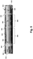
- Fig. 5 is a side view of an embodiment of a support member 530, according to aspects of the present disclosure.
- Support member 530 may exhibit similar characteristics as support member 230 shown in Fig. 4 .
- the support member 530 can be referenced as a unibody in some instances.
- the support member 530 may also be composed of a metallic material, such as stainless steel, gold, silver, copper, and/or alloy, or a non-metallic material, such as a plastic or polymer as previously described in relation to support member 230.
- the support member 530 can be ferrule having a distal portion 562 and a proximal portion 564.
- Support member 530 may also comprise a distal flange or end 532 and proximal flange or end 534.
- the support member 530 may also be manufactured according to any suitable process. These processes may be substantially similar to manufacturing processes of support member 230. Support member 530 may comprise one or more stands extending radially from support member 530. These stands may be substantially similar to stands 242 and 244 and may serve similar functions. Support member 530 may comprise additional or fewer stands depending on the specific application of a particular embodiment. Support member 530 may be of any suitable shape. As shown in Fig. 5 , one embodiment of support member 530 may be generally cylindrical in shape. Other shapes of the support member 530 are fully contemplated including geometrical, non-geometrical, symmetrical, and non-symmetrical cross-sectional profiles. Support member 530 may be of any suitable size.
- support member 530 may be of sufficiently small diameter to maneuver through the coronary vasculature surrounding the human heart.
- the support member 530 can be relatively larger for peripheral applications, to maneuver through vasculature in the legs, abdomen, neck, and other anatomies of the human body.
- the intraluminal imaging device is to be used to image still larger lumens, either within organic or inorganic lumens, the overall dimensions of support member 530 may be adjusted and increased accordingly.
- support member 530 may comprise any number of stands of any suitable shape extending in an outward direction generally radially from the support member ferrule.
- stand 242 may be positioned at a location near the distal end 532 of support member 530 and support member 530 may additionally comprise a proximal stand 544 positioned near the proximal end 534 of support member with an intermediate stand 542 positioned therebetween.
- These three stands, the distal stand 242, the intermediate stand 542, and the proximal stand 544 may serve various purposes or functions within ultrasound imaging assembly 110.
- distal stand 242, intermediate stand 542, and proximal stand 544 may be to provide support for flexible substrate 214.
- intermediate stand 542 may be placed at a location proximal to the transducers 212 disposed on the surface of flexible substrate 214.
- Distal stand 242 and intermediate stand 542 define a region 580 extending longitudinally along the support member 530.
- Transducers 212 on flexible substrate 214 may be positioned over region 580 such that transducers 212 are situated generally at the same longitudinal position as region 580 and radially outward from region 580.
- the ferrule surface of support member 530 at region 580 between distal stand 242 and intermediate stand 542 may comprise one or more recesses 582.
- Recesses 582 may be configured to extend completely through the exterior of support member 530 to the interior or inner lumen 236 within support member 530. Recesses 582 may thereby allow direct access to the inner lumen 236 of support member 530 from the exterior environment of support member 530 and vice versa.
- One function of recesses 582 may be to introduce acoustic backing material 246 ( Fig. 4 ) to be positioned within the lumen created by distal stand 242, intermediate stand 542, region 580 and the inner surface of flexible substrate 214.
- Acoustic backing material 246 may be used to attenuate signals which may propagate from transducers 212 of flexible substrate 214 in an inwardly radial direction. Acoustic backing material 246 may also attenuate reflected waves received by transducers 212 which may propagate from a source radially inward of transducers 212. Due to these acoustic properties, acoustic backing material is positioned radially inward of transducers 212.
- Intermediate stand 542 may serve as a barrier between region 580 filled with acoustic backing material 246 and region 590 which may not need to be filled with acoustic backing material 246.
- Intermediate stand 542 and proximal stand 544 may define region 590 extending longitudinally along the support member 530.
- Integrated circuit controller chip(s) 206A and 206B may be positioned over region 590 such that integrated circuit controller chip(s) 206A and 206B are situated generally at the same longitudinal position as region 590 and radially outward from region 590.
- the ferrule surface of support member 530 at region 590 between intermediate stand 542 and proximal stand 544 may comprise one or more recesses 592. Recesses 592 may be configured to extend completely through the exterior of support member 530 to the interior or inner lumen 236 within support member 530.
- Recesses 592 may thereby allow direct access to the inner lumen 236 of support member 530 from the exterior environment of support member 530 and vice versa.
- One function of recesses 592 may be to introduce filling material 820 ( Fig. 8 ) to be positioned within the lumen created by intermediate stand 542, proximal stand 544, region 590 and the inner surface of flexible substrate 214.
- Region 590 may be composed of any suitable metallic or non-metallic material.
- region 590 may be filled with an underfill material to the support the chips 206A and 206B.
- the underfill material can be an adhesive, an epoxy, etc.
- the underfill material need not have acoustic attenuating properties as the acoustic backing material 246 because the underfill material is under the chips 206A, 206B, and not the transducers 212.
- Filling material 820 may serve to physically support flexible substrate 214 generally around region 590. Filling material 820 may be positioned at a location radially inward of integrated circuit controller chip(s) 206A and 206B as well as other components previously mentioned that may be positioned on the surface of flexible substrate 214.
- recess 620 positioned near the distal end 532 of support member 530. As will be discussed in reference to Fig. 6 , recess 620 may extend completely through the exterior of support member 530 to the interior or inner lumen 236 within support member 530. Recess 620 may thereby allow direct access to the inner lumen 236 of support member 530 from the exterior environment of support member 530 and vice versa.
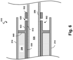
- Fig. 6 is a diagrammatic cross-sectional view of the distal portion of an ultrasound imaging assembly 610 before a tip member 710 ( Fig. 7 ) is coupled to the ultrasound imaging assembly 610, according to aspects of the present disclosure.
- Ultrasound imaging assembly 610 may be substantially similar to ultrasound imaging assembly 110 previously presented or may differ.
- ultrasound imaging assembly 610 may comprise support member 530.
- Support member 530 can be tubular in shape and define a lumen 536 extending longitudinally therethrough.
- the lumen 536 can be sized and shaped to receive the guide wire 118.
- Lumen 536 may further be configured to receive inner member 256 therethrough.
- Support member 530 may further comprise a stand 640.
- Stand 640 may extend radially from support member 530.
- Stand 640 may also be referred to as a lip or shoulder.
- Stand 640 and support member 530 may be integrally formed as a unitary structure, while in other embodiments, stand 640 may be formed of a different component than support member 530.
- Stand 640 may be fixedly coupled to support member 530.
- stand 640 may be manufactured of different materials than support member 530, or the same materials.
- stand 640 may be manufactured of any suitable material, including metallic and non-metallic materials depending on the specific application of a particular embodiment.
- Stand 640 may be of any suitable shape.
- stand 640 may be generally circular extending completely around and in direct contact with support member 530.
- stand 640 may be replaced with multiple components spaced a distance apart from one another and positioned at the same longitudinal position around support member 530.
- stand 640 may extend any suitable distance from support member 530.
- Ultrasound imaging assembly 610 may further comprise flexible substrate 214.
- Flexible substrate 214 may be fixedly coupled to the outer surface of stand 640 in such a way that stand 640 may support flexible substrate 214.
- Flexible substrate 214 may thereby be positioned at an appropriate space away from support member 530 so as to create a gap between these two components.
- This gap is created by stands which may be substantially similar to stand 640, stand 242, stand 542, or stand 544 which extend radially outward from the ferrule of support member 530 in such a way that the outer diameter of the stands is greater than the overall diameter of the support member 530 ferrule.
- This gap may be filled with any suitable materials or components, including but not limited to an acoustic backing material 246, filling material 820 ( Fig.
- the gap between flexible substrate 214 and support member 530 as defined by stand 640 is filled with acoustic backing material 246.
- acoustic backing material 246 To improve acoustic performance, any cavities between the flexible substrate 214 and the surface of the support member 230 are generally filled with a backing material 246.
- the liquid backing material 246 has a relatively low acoustic impedance, and can be introduced between the flexible substrate 214 and the support member 230 via passageways in the support member 230 (not shown).
- Backing material 246 may be used to attenuate or absorb acoustic energy not directed to the anatomy of interest.
- the backing material 246 fills the space between the support member 230 and the transducer array 124 as well as the gaps between adjacent individual transducers 212.
- the backing material 246 possesses the ability to highly attenuate the ultrasound which is transmitted by the transducer array 124.
- the backing material 246 also provides support for the transducer elements.
- the backing material 246 can be cured to allow it to solidify and set in a sufficiently short period of time to meet manufacturing needs.
- a number of known materials meeting the above described criteria for a good backing material will be known to those skilled in the art.
- An example of such a backing material comprises a mixture of epoxy, hardener and phenolic microballoons providing high ultrasound signal attenuation and satisfactory support for the ultrasound transducer assembly.
- Still other materials for baking material 246 may include polymers, graphite, composites, ceramics, metals, or any combination thereof.
- support member 530 may comprise a plurality of recesses 620. In its cross-sectional view, support member 530 is pictured comprising two such recesses 620. However, support member 530 may comprise only one, three, four, or more recesses 620. In an embodiment, recess 620 may extend completely through the distal portion 562 of support member 530. For example, recess 620 may extend from surface 622 of recess 620 completely through a portion of support member 530 to the opposing surface 612 of support member 530. In this configuration, recess 620 allows for direct access to or exposes inner member 256.
- recess 620 may not extend completely through support member 530 such that recess 620 does not expose inner member 256. In such an embodiment, recess 620 may only be configured on surface 622 of support member 530. Opposing surface 612 would not comprise any such recess, but would be substantially uniform. In still other embodiments, support member 530 may comprise some recesses which extend completely through support member 530, and some recesses which do not extend completely through support member 530. Recess 620 may be of any suitable size or shape. In some embodiments, recess 620 is of a generally circular shape. In other embodiments, the shape of recess 620 may be that of a rectangle, square, triangle, or any other polygon. Other shapes are also contemplated including geometrical, non-geometrical, symmetrical and non-symmetrical shapes. Recess 620 may also be referred to as a hole or cavity.
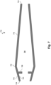
- Fig. 7 is a diagrammatic cross-sectional view of a tip member 710, according to aspects of the present disclosure.
- Tip member 710 may also be referred to as a molded tip or lead tip.
- Tip member 710 may be constructed of any suitable material including a non-metallic material, such as a plastic or polymer.
- tip member 710 is the leading component of intraluminal imaging device 602 while the device travels through a body lumen.
- Tip member 710 may be composed of any appropriate material, but may be flexible so as to not penetrate the body lumen.
- Tip member 710 may comprise a distal end 716 and a proximal end 718.
- Tip member 710 may also be of a generally conical shape.
- tip member 710 may be of any suitable shape configured to allow an intraluminal imaging device to easily maneuver through the vasculature of a patient.
- tip member 710 may be of any suitable size configured to accomplish the desired result in any particular application.
- the overall diameter of tip member 710 at a distal end 716 may be smaller than the overall diameter of tip member 710 at a proximal end 718.
- the overall diameter of tip member 710 at a proximal point 718 may be smaller than the overall diameter of tip member 710 at a point 722 positioned between distal end 716 and proximal end 718.
- Tip member 710 may then further comprise two sloped or tapered surfaces, surface 712 and surface 714 sloping in opposite directions from one another.
- surface 712 and surface 714 comprise opposite tapers.
- surface 712 and surface 714 may extend towards the radial center of tip member 710 and away from point 722.
- Point 722 also need not be a singular longitudinal point along tip member 710.
- tip member 710 may not comprise surface 714.
- the overall diameter of proximal end 718 may be the largest overall diameter at any longitudinal location of tip member 710 making tip member 710 a purely conical shape.
- Tip member 710 may further define an inner lumen 730.
- Lumen 730 may comprise a space between the outer surfaces of tip member 710 and may be configured to receive inner member 256.
- the overall diameter of inner lumen 730 may be substantially similar to the diameter of inner member 256 or may be larger depending on the application so as to allow additional components to be received within lumen 730.
- Tip member 710 may further comprise a plurality of protrusions 720 which extend from an inner surface 724 of tip member 710 in an inward direction towards the radial center of tip member 710 and protruding into lumen 730.
- tip member 710 may comprise only one such protrusion 720, or may comprise two, three, four, or more protrusions 720.
- the dimensions of protrusion 720 may be of any suitable dimension and may be configured to correspond to or be received by recesses 620 of support member 530.
- protrusion 720 may have a generally circular cross-sectional profile shape.
- protrusion 720 may be used for protrusion 720.
- Fig. 7 presents protrusion 720 extending in a direction directly towards the radial center of tip member 710, in other embodiments, protrusion 720 may extend at any suitable angle, e.g. an oblique angle or the like, in an inward, radial direction.
- the overall width of protrusion 720 need not be uniform.
- protrusion 720 and tip member 710 may be integrally formed as a unitary structure, while in other embodiments protrusion 720 and tip member 710 may be formed of different components. As such, protrusion 720 may be constructed of a different material than tip member 710 or may be constructed of the same material.
- Fig. 8 is a diagrammatic cross-sectional view of the connection of the distal end of the ultrasound imaging assembly 610 shown in Fig. 6 and the proximal end of the tip member 710 shown in Fig. 7 , according to aspects of the present disclosure.
- the diameter of tip member 710 at proximal end 718 may be smaller than the overall diameter of the lumen created by flexible substrate 214 in its rolled configuration, such that the proximal end 718 may be received inside the distal portion of flexible substrate 214 in its rolled configuration, as shown in Fig. 8 .
- the distal end or flange 232 of support member 530 is received within lumen 730 ( Fig. 7 ) of tip member 710.
- proximal end 718 of tip member 710 may be in direct contact with and abut stand 640 of support member 530. In other embodiments, proximal end 718 of tip member 710 may not abut stand 640 but may positioned at a location distal of stand 640 so as to create a gap.
- protrusions 720 of tip member 710 may be received into corresponding recesses 620 of support member 530.
- Protrusions 720 may be of the same cross-sectional profile shape as recesses 620 or may be of a different cross-sectional profile shape.
- Fig. 8 depicts two such protrusions 720 and two corresponding recesses 620, there may be more or fewer protrusions 720 and corresponding recesses 620.
- both protrusions 720 and recesses 620 depicted in Fig. 8 are positioned at the same longitudinal location along ultrasound imaging assembly 610, this need not be the case.
- a protrusion 720 located on tip member 710 and a corresponding recess 620 located on support member 530 may be located at a point proximal or distal to another protrusion 720 and corresponding recess 620.
- protrusion 720 may extend completely through recess 620 such that the distal end of protrusion 720 is in direct contact with the outer surface of inner member 256.
- Tip member 710, including protrusion 720 may also be of the same material as inner member 256.
- This embodiment provides a strong mechanical bond between support member 530 and tip member 710.
- recess 620 may not extend completely through support member 530 from surface 622 to surface 612.
- recess 620 may only be positioned on surface 622 and surface 612 may be substantially uniform.
- the proximal end of protrusion 720 would not extend completely through support member 530 and would not be in direct contact with the outer surface of inner member 256. A mechanical bond would still be formed between support member 530 and tip member 710 in this embodiment.
- a protrusion may be positioned at the distal region of support member 530 and a corresponding recess may be positioned on tip member 710.
- the protrusion may be of similar geometry to protrusion 720.
- the protrusion may extend radially outward from the ferrule of support member 530 and may be of the same material as support member 530 such that the protrusion and support member 530 are one unitary structure.
- the protrusion may also be of a different material.
- the protrusion may be positioned on surface 622 of support member 530. A recess positioned on the tip member 710 may receive the protrusion.
- ultrasound imaging assembly 610 may be subject to a reflow process after assembly.
- This reflow process may be substantially similar to reflow processes known and readily available to those skilled in the art.
- the temperature of the surrounding environment of ultrasound imaging assembly 610 may be increased above the melting point of the materials used to construct protrusion 720 of tip member 710 and inner member 256, but be kept below the melting point of other components of ultrasound imaging assembly 610 including but not limited to support member 530, flexible substrate 214, and others.
- the flexible substrate 214 may be composed of a thermal set material that will not melt during reflow, such as Kapton ® or any other suitable material.
- the range of settings during a reflow process may be configured based on visual inspection by a manufacturer of the ultrasound imaging assembly 610.
- the range of settings during a reflow process may comprise the temperature of the environment during reflow, the areas or parts of ultrasound imaging assembly 610 to be included in the reflow process, or other features or characteristics.
- Other components may also be shielded to avoid melting during a reflow process. In some embodiments, shielding components may not be necessary due to characteristics and/or properties of the heat generating element used during a reflow process.
- the travel distance of the heat may depend on the length of the heated die.
- protrusion 720 and inner member 256 may begin a phase transition from a substantially solid material to a liquid material such that, once the temperature cools, the two components fuse together becoming one unitary structure and ensuring a very strong bond between tip member 710, inner member 256, and support member 530.
- protrusion 720 is constructed of a different material than tip member 710, protrusion 720 alone fuses with inner member 256 such that they become a unitary structure.
- protrusion 720 may be selected with a melting point below the environmental temperature of the ultrasound imaging assembly 610 during the reflow process and the material of tip member 710 may be selected with a melting point above the environmental temperature. In this embodiment, only protrusion 720 may phase transition and fuse to inner member 256 while tip member 710 may retain its original shape.
- adhesive 810 may be applied to the distal connection between tip member 710 and ultrasound imaging assembly 610.
- Adhesive 810 may fill gaps left between the outer surface 714 of tip member 710 and the inner surface of flexible substrate 214 in its rolled configuration. Adhesive 810 may also fill gaps left between the inner surface 724 of tip member 710 and surface 622 ( Fig. 6 ) of support member 530 and may extend distally within tip member 710.
- Adhesive 810 may be any particular type of suitable adhesive, such as epoxy, cyanoacrylate, urethane adhesive, and/or acrylic adhesives, as well as others.
- Adhesive 810 may be liquid of any suitable viscosity. In some embodiments, adhesive 810 is not light cured (e.g., not UV cured).
- Fig. 9 is a partial cutaway view of another embodiment of the connection of the distal end of a support member 930 and the proximal end of a tip member 910, according to aspects of the present disclosure.
- Support member 930 may be similar to support member 530 presented previously and may serve similar functions as support member 530.
- Support member 930 may also be referred to as a unibody.
- support member 930 may also be composed of a metallic material, such as stainless steel, or a non-metallic material.
- the support member 930 can be ferrule and may be manufactured according to any suitable process.
- Support member 930 may comprise one or more stands 940 extending radially from support member 930. These stands may be substantially similar to stands 640, 242 and 244 and may serve similar functions. Support member 930 may be of any suitable size.
- support member 930 may comprise a recess 920 at the distal portion 962 of support member 930.
- Recess 920 may be substantially similar to recess 620 presented in Fig. 6 .
- recess 920 may be of any suitable shape.
- recess 920 may be of a generally oval shape.
- recess 920 may be circular, or have a cross-sectional profile of any other suitable shape.
- Recess 920 may extend completely through the surface of support member 930 such that the outer environment of support member 930 may be in direct contact with the inner lumen within the axial center of support member 930.
- Recess 920 may receive a protrusion positioned on the inner surface of tip member 910. Such a protrusion may be substantially similar to protrusion 720. Recess 920 may allow a protrusion on the inner surface of tip member 910 to come into direct contact with the outer surface of inner member 256.
- support member 930 may further comprise one or more ridges 932 positioned around the outer surface of the distal portion 962 of support member 930.
- Ridges 932 may also be referred to as barbs, spikes, anchors, flanges, collars, or ribs.
- ridges 932 and support member 930 may be integrally formed as a unitary structure. Ridges 932 may be of any suitable shape. As shown in Fig. 9 , in some embodiments, ridges 932 may comprise two outer surfaces, distal surface 936 and proximal surface 938.
- Distal surface 936 may be sloped such that the outer diameter of support member 930 is substantially similar to the overall outer diameter of support member 930 at a distal point of a ridge 932 of support member 930 and then gradually increases to a larger diameter at a proximal point on ridge 932.
- Surface 938 may extend in a substantially orthogonal direction to the outer surface of support member 930 as shown in Fig. 9 .
- a sloped distal surface 936 and an oblique proximal surface 938 results in a more secure connection between tip member 710 and support member 930 by allowing tip member to move in a proximal direction, as indicated by arrow 990, when being connected to support member 930 but not allowing tip member to move in a distal direction, as indicated by arrow 995.
- surface 938 may be a sloped surface as well.
- ridges 932 may comprise additional surfaces and may be of any suitable cross-sectional shape.
- the cross-sectional profile of ridges 932 may be substantially rectangular or semi-circular among other geometric and non-geometric shapes.
- ridges 932 may extend completely around the outer surface of support member 930 at a longitudinal point along support member 930. In other embodiments, ridges 932 may only extend partially around outer surface of support member 930. For example, ridges 932 may extend around substantially half of the outer surface of support member 930, substantially a quarter of the outer surface of support member 930 or around any other suitable portion of support member 930. In addition, at the same longitudinal point along support member 930, there may be positioned more than one such ridge 932 extending along some fraction of the outer circumference of support member 930.
- the support member 930 can include multiple ridges 932. Three such ridges 932 are depicted in Fig. 9 , however, fewer or more ridges 932 may be used in the design of support member 930. For example, one, two, three, four, five, or more ridges 932 may be placed along the outer surface of the distal portion 962 of support member 930. Ridges 932 may be in any position relative to recess 920. As shown in Fig. 9 , recess 920 may overlap with one or more of ridges 932, however, in other embodiments, recess 920 may be positioned between, proximal or distal of one or more ridges 932.
- tip member 910 may comprise one or more grooves 934.
- Grooves 934 may also be referred to as troughs, channels, indentations, notches, or other suitable terms.
- grooves 934 may be of a substantially similar shape as ridges 932 such that ridges 932 may be received into grooves 934 when the proximal end of tip member 910 is brought into contact with the distal end of support member 930.
- grooves 934 be of any suitable cross-sectional shape.
- the cross-sectional profile of grooves 934 may be substantially rectangular or semi-circular among other geometric and non-geometric shapes, Similarly, grooves 934 may extend completely around the inner surface of tip member 910 at a longitudinal point along tip member 910. In other embodiments, grooves 934 may only extend partially around inner surface of the tip member 910. In addition, at the same longitudinal point along the inner surface of tip member 910, there may be positioned more than one such groove 934 extending along some fraction of the inner circumference of tip member 910. In addition, although three such grooves 934 are depicted in Fig. 9 , fewer or more grooves 934 may be used in the design of tip member 910.
- tip member 910 may comprise one or more protrusions substantially similar to protrusion 720 previously discussed. These protrusions may be positioned at any suitable location within the inner surface of tip member 910 and in any position relative to grooves 934.
- ridges 932 and grooves 934 may be reversed.
- ridges may be located on the inner surface of the proximal portion of tip member 910. These ridges may extend inwardly radially from the inner surface of tip member 910 so as to protrude into the inner lumen created by tip member 910.
- the distal portion 962 of support member 930 may comprise corresponding grooves similar to grooves 934 depicted in Fig. 9 .
- these grooves may be positioned on the outer surface of the distal portion 962 of support member 930 so as to create a recess or void extending inwardly radially into the outer surface of support member 930.
- the outer surface of support member 930 may comprise one or more of both ridges and grooves as previously described and the inner surface of tip member 910 may similarly comprise one or more of both ridges and grooves as previously described.
- This plurality of both ridges and grooves positioned on both support member 930 and tip member 910 may be configured to receive one another or interlock with one another creating a substantially stronger coupling of support member 930 and tip member 910.
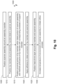
- Fig. 10 is a flow diagram of a method 1000 of a phase of assembling an intraluminal imaging device 102 according to an embodiment of the present disclosure.
- the method 1000 can include mechanically coupling tip member 710 to intraluminal imaging device 102.
- method 1000 includes a number of enumerated steps, but embodiments of method 1000 may include additional steps before, after, or in between the enumerated steps. In some embodiments, one or more of the enumerated steps may be omitted, performed in a different order, or performed concurrently.
- the steps of method 1000 can be carried out by a manufacturer of the intraluminal imaging device 102 and/or a manufacturer of any other component discussed in the present disclosure. Method 1000 will be described with reference to Figs.
- FIGS. 13-16 are side views of various components of the ultrasound imaging assembly 102 during various steps of manufacturing.
- Figs. 13-16 illustrate assembly steps for various components of the ultrasound imaging assembly 102, such as the connection between the intraluminal imaging device 102 and the tip member 710.
- method 1000 includes positioning scanner assembly or ultrasound imaging assembly 110 around an assembly mandrel 1110 ( Fig. 11 ).
- An assembly mandrel 1110 may be used to support the ultrasound imaging assembly 110 during various stages of manufacturing.
- Assembly mandrel 1110 may be of any suitable length.
- the diameter of assembly mandrel 1110 may correspond to the inner diameter of the inner member 256 or may differ.
- ultrasound imaging assembly 110 may be constructed without the use of assembly mandrel 1110.
- Assembly mandrel 1110 may also be referred to as a support shaft or support rod.
- Assembly mandrel 1110 may be constructed of any suitable material, including metallic and non-metallic materials.
- assembly mandrel 1110 may be a rigid structure or semi-rigid structure.
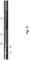
- method 1000 includes positioning tip member 710 around assembly mandrel 1110 at some point distal to scanner assembly or ultrasound imaging assembly 110 as shown in Fig. 11.
- Fig. 11 is a side view of the intraluminal imaging device 102 and tip member 710 positioned around an assembly mandrel 1110 before coupling the tip member 710 to the scanner assembly 110, according to aspects of the present disclosure.
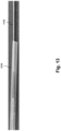
- method 1000 includes positioning the proximal portion of tip member 710 within the distal portion of ultrasound imaging assembly or scanner assembly 110 and interlocking protrusions 720 of tip member 710 with corresponding recesses 620 of support member 530 as shown in Fig. 12.
- Fig. 12 is a side view of the ultrasound imaging assembly or scanner assembly 110 and a tip member 710 positioned around an assembly mandrel 1110 after coupling the tip member 710 to the scanner assembly 110, according to aspects of the present disclosure.
- protrusions 720 of tip member 710 may be received into corresponding recesses 620 of support member 530 creating a strong mechanical connection between support member 530 and tip member 710.
- Protrusions 720 may also be in direct contact with inner member 256 such that during a subsequent reflow process, protrusions 720 and inner member 256 fuse together and becoming a unitary structure.
- method 1000 includes applying adhesive 810 to the distal connection of the tip member 710 and ultrasound imaging assembly or scanner assembly 110.
- Adhesive 810 may additionally be applied to the connection of tip member 710 and scanner assembly 110 and fill gaps between the outer surface 714 of tip member 710 and the inner surface of flexible substrate 214 in its rolled configuration and gaps between the inner surface 724 of tip member 710 and outer surface 622 of support member 530.
- Adhesive 810 applied in such a manner may increase the strength of the connection between tip member 710 and ultrasound imaging assembly 110 as described in relation to Fig. 8 .
- method 1000 includes positioning a heat shrink layer 1310 around tip member 710 and ultrasound imaging assembly or scanner assembly 110.
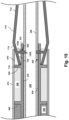
- Fig. 13 is a side view of a heat shrink layer 1310 positioned around an ultrasound imaging assembly or scanner assembly 110 and a tip member 710 supported by an assembly mandrel 1110, according to aspects of the present disclosure.
- a heat shrink layer 1310 may be applied around the scanner assembly 110 and related components prior to a reflow process.
- Heat shrink layer 1310 may be constructed of any one of a variety of thermoplastics, including polyolefin, polyvinyl chloride, polychloroprene (e.g., NEOPRENE ® ), among others.
- Heat shrink layer 1310 may be positioned at a location around the outer surface of scanner assembly 110 and then subjected to increased temperature, causing heat shrink layer 1310 to contract inwardly around scanner assembly 110.
- Heat shrink layer 1310 may be used to shield components such as the inner member 256, outer member 254, scanner assembly 110, or other components that are incompatible with high temperature exposure during a reflow process. In some embodiments, heat shrink layer 1310 may also serve other purposes as well. After a reflow process is completed, heat shrink layer 1310 may be removed from the intraluminal imaging device.
- method 1000 includes increasing the temperature of the environment of the ultrasound imaging assembly or scanner assembly 110 to initiate a reflow process.
- the temperature of the surrounding environment of ultrasound imaging assembly or scanner assembly 110 may be increased above the melting point of the materials used to construct protrusion 720 of tip member 710 and inner member 256, but be kept below the melting point of other components of scanner assembly 110.
- Protrusion 720 and inner member 256 may then begin a phase transition such that the two components fuse together becoming one unitary structure and ensuring a very strong bond between tip member 710, inner member 256 and support member 530.
- heat shrink layer 1310 may be removed at this phase of assembly. In other embodiments, heat shrink layer 1310 may not be removed.
- additional steps may be performed to reach a final product including applying hydrophobic or hydrophilic coatings to various components or portions of the scanner assembly 110 and its associated components. Other steps may be taken in different embodiments as well.
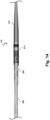
- Fig. 14 is a side view of an ultrasound imaging assembly or scanner assembly 110 after assembly, according to aspects of the present disclosure.
- Ultrasound imaging assembly or scanner assembly 110 is connected at a distal end to tip member 710 and connected at a proximal end to outer member 254.
- Flexible substrate 214 is depicted in Fig. 14 wrapped around a support member.
- a plurality of conductors, transmission line bundle, or cables 112 are also depicted connected at a proximal end of scanner assembly 110 extending proximally from the assembly.
- Embodiments of the presently disclosed invention may comprise protrusions and/or corresponding recesses/grooves at any suitable location of the intraluminal device.
- one or more protrusion(s) and/or one or more recesses/grooves can be provided on tip member 710, the scanner assembly 110, the flexible substrate 214, the support member 230, the inner member 256, and/or any other component described in the present application.
- a flexible substrate 214 can include a protrusion that extends radially inward and is received within a recess/groove of the support member 230, the tip member 710, and/or the inner member 256.
- the inner member 256 can include a protrusion that extends radially outward and is received within a recess/groove of the flexible substrate 214, the support member 230, and/or the tip member 710.
- One or more embodiments of the present disclosure advantageously increase coupling strength between components. This advantageously ensures that the components cannot come apart. This improves patient safety by minimizing and/or eliminating the possibility of components separating while the intraluminal device is within the patient's body.
- Such strength can be added as the result of mechanical engagement between components (e.g., physical contact resulting from the protrusion of one component being received within a recess/groove of another component).
- the material of multiple components can be joined together. For example, polymer material(s) can be fused or melted together during a reflow process.
- the mechanical engagement between components is supported by adhesive surrounding and in contact with the joint.
- Fig. 15 is a diagrammatic cross-sectional view of an embodiment of the connection between components at the distal portion of the intraluminal imaging device, according to aspects of the present disclosure.
- Fig. 15 includes a protrusion 1520 of the tip member 710.
- Protrusion 1520 may be substantially similar to protrusion 720 previously mentioned or may differ.
- protrusion 1520 may be configured to be received into recess 620 of support member 230.
- Protrusion 1520 may also be configured to be received into an additional recess 1525 within inner member 256, such that the tip of protrusion 1520 may be in direct contact with lumen 236 created by inner member 256.
- recess 1525 may not extend completely through inner member 256 as shown in Fig.
- recess 1525 may only extend part way through inner member 256 such as to extend into the outer surface of inner member 256 but not through the inner surface of inner member 256. In either of these embodiments, however, during a reflow process, protrusion 1520 fuses with inner member 256 so as to create a strong bond between the two components and forming one unitary structure.
- Fig. 16 is a diagrammatic cross-sectional view of an embodiment of the connection between components at the distal portion of the intraluminal imaging device, according to aspects of the present disclosure.
- Fig. 16 includes a protrusion 1620 of the tip member 710.
- Protrusion 1620 may be substantially similar to protrusion 720 and/or protrusion 1520 previously mentioned or may differ.
- protrusion 1620 may be configured to be received into recess 1625 of inner member 256.
- Recess 1625 may be substantially similar to recess 1525 previously mentioned.
- recess 1625 may extend completely through inner member 256 such that recess 1625 may be detected on both the outer surface and inner surface of inner member 256.
- recess 1625 may only extend part way through inner member 256 such as to extend into the outer surface of inner member 256 but not through the inner surface of inner member 256. In either of these embodiments, however, during a reflow process, protrusion 1620 fuses with inner member 256 so as to create a strong bond between the two components and forming one unitary structure. As shown in Fig. 16 , protrusion 1620 may be positioned at some location distal of support member 230 so as to not extend through any recess on or within support member 230. In some embodiments, the distal tip of support member 230 may abut protrusion 1620. In other embodiments, protrusion 1620 may be spaced from the support member 230 so as not to be in contact with support member 230.
- Fig. 17 is a diagrammatic cross-sectional view of an embodiment of the connection between components at the distal portion of the intraluminal imaging device, according to aspects of the present disclosure.
- Fig. 17 includes a protrusion 1720 of the tip member 710.
- Protrusion 1720 may be substantially similar to protrusion 720, protrusion 1520, and/or protrusion 1620 except that protrusion 1720 may extend radially outward from the outward surface of tip member 710.
- protrusion 1720 may be configured to be received into recess 1725 of flexible substrate 214.
- Recess 1725 may be substantially similar to recess 1525 and/or recess 1625 previously mentioned but may be positioned within support member 214.
- recess 1725 may extend completely through flexible substrate 214 such that recess 1725 may be detected on both the outer surface and inner surface of flexible substrate 214.
- recess 1725 may only extend part way through flexible substrate 214 so as to extend into the inner surface of flexible substrate 214 but not through the outer surface of flexible substrate 214.
- protrusion 1720 fuses with flexible substrate 214 so as to create a strong bond between the two components and forming one unitary structure.
- protrusion 1720 may not bond with flexible substrate 214 during a reflow process.
- Protrusion 1720 may be positioned at any suitable location and a corresponding recess within flexible substrate 214 may be positioned at any suitable location within, on, or around scanner assembly 110.
- an additional protrusion may extend from tip member 710 in a proximal direction towards stand 640 of support member 230. Such a protrusion may be received into a corresponding recess positioned within stand 640 of support member 230. Such a recess may be substantially similar to recess 235 of Fig. 4 or may differ. Such a configuration may provide a stronger connection between tip member 710 and the scanner assembly 110. In some embodiments, a protrusion may extend distally from the stand 640 and be received within a recess of the tip member 710.
- the intraluminal device can include a pressure sensor, flow sensor, temperature sensor, and/or electrode(s).
- the intraluminal device can include any suitable type of optical sensor.
- Any type of intraluminal imaging is contemplated, including intraluminal devices with an optical coherence tomography (OCT) imaging element and/or an intracardiac echocardiography (ICE) transducer array.
- OCT optical coherence tomography
- ICE intracardiac echocardiography
- One or more sensing devices of the intraluminal device can obtain physiological data (pressure, flow, temperature, images, etc.) associated with the body lumen in which intraluminal device is positioned.
- the intraluminal device is a diagnostic device. In some embodiments, the intraluminal device is a therapeutic device that delivers a therapy to the body lumen. Such a therapeutic intraluminal device can have a treatment component at a distal portion (e.g., a balloon, an ablation electrode, a laser, an atherectomy blade, etc.)
- a treatment component at a distal portion e.g., a balloon, an ablation electrode, a laser, an atherectomy blade, etc.
Landscapes
- Health & Medical Sciences (AREA)
- Life Sciences & Earth Sciences (AREA)
- Medical Informatics (AREA)
- Biophysics (AREA)
- Nuclear Medicine, Radiotherapy & Molecular Imaging (AREA)
- Pathology (AREA)
- Radiology & Medical Imaging (AREA)
- Engineering & Computer Science (AREA)
- Biomedical Technology (AREA)
- Heart & Thoracic Surgery (AREA)
- Physics & Mathematics (AREA)
- Molecular Biology (AREA)
- Surgery (AREA)
- Animal Behavior & Ethology (AREA)
- General Health & Medical Sciences (AREA)
- Public Health (AREA)
- Veterinary Medicine (AREA)
- Gynecology & Obstetrics (AREA)
- Vascular Medicine (AREA)
- Ultra Sonic Daignosis Equipment (AREA)
Claims (15)
- Intraluminale Bildgebungsvorrichtung (102), umfassend:ein flexibles, längliches Element (121), das konfiguriert ist, in einem Körperlumen eines Patienten positioniert zu werden, wobei das flexible, längliche Element einen proximalen Abschnitt und einen distalen Abschnitt umfasst;eine Ultraschallbildgebungsanordnung, die am distalen Abschnitt des flexiblen länglichen Elements angeordnet ist und konfiguriert ist, um Ultraschalldaten zu erhalten, während sie im Körperlumen positioniert ist; undein Spitzenelement (710), das mit der Ultraschallbildgebungsanordnung gekoppelt ist, wobei das Spitzenelement einen Polymervorsprung (720) umfasst,wobei die Ultraschallbildgebungsanordnung eine Aussparung (620, 920, 1525, 1625, 1725) umfasst, die einen Polymerabschnitt der Ultraschallbildgebungsanordnung freilegt, und wobei der in der Aussparung aufgenommene Vorsprung mit dem freigelegten Polymerabschnitt der Ultraschallbildgebungsanordnung verschmolzen ist, um eine einheitliche Struktur zu bilden.
- Intraluminale Bildgebungsvorrichtung nach Anspruch 1, wobei die Ultraschallbildgebungsanordnung ein Trägerelement (230) und ein flexibles Substrat (214) umfasst, das um das Trägerelement herum positioniert ist, wobei das Trägerelement die Aussparung (620) umfasst.
- Intraluminale Bildgebungsvorrichtung nach Anspruch 2,wobei das Trägerelement einen proximalen Abschnitt und einen distalen Abschnitt umfasst, wobei die Aussparung am distalen Abschnitt des Trägerelements angeordnet ist,wobei das Spitzenelement einen proximalen Abschnitt und einen distalen Abschnitt umfasst, wobei der Vorsprung am proximalen Abschnitt des Spitzenelements angeordnet ist,wobei der distale Abschnitt des Trägerelements mit dem proximalen Abschnitt des Spitzenelements gekoppelt ist.
- Intraluminale Bildgebungsvorrichtung nach Anspruch 2, wobei das flexible, längliche Element ein inneres Element (256) umfasst, das sich durch das Trägerelement hindurch erstreckt, sodass die Aussparung einen Abschnitt des inneren Elements freilegt.
- Intraluminale Bildgebungsvorrichtung nach Anspruch 4, wobei das Trägerelement eine erste Oberfläche und eine gegenüberliegende zweite Oberfläche umfasst, wobei sich die Aussparung von der ersten Oberfläche zur zweiten Oberfläche erstreckt.
- Intraluminale Bildgebungsvorrichtung nach Anspruch 4, wobei das Spitzenelement ein erstes Polymer umfasst und das innere Element ein zweites Polymer umfasst.
- Intraluminale Bildgebungsvorrichtung nach Anspruch 2, wobei sich der Vorsprung radial nach innen erstreckt.
- Intraluminale Bildgebungsvorrichtung nach Anspruch 2, wobei sich der Vorsprung radial nach außen erstreckt.
- Intraluminale Bildgebungsvorrichtung nach Anspruch 2, wobei das Trägerelement eine Vielzahl von Aussparungen umfasst und wobei das Spitzenelement eine Vielzahl von Vorsprüngen umfasst, wobei die Vielzahl von Vorsprüngen innerhalb der Vielzahl von Aussparungen aufgenommen ist.
- Intraluminale Bildgebungsvorrichtung nach Anspruch 2, wobei das Spitzenelement eine Außenoberfläche umfasst, wobei die Außenoberfläche einen ersten geneigten Abschnitt und einen gegenüberliegenden zweiten geneigten Abschnitt umfasst und wobei der Vorsprung mit dem ersten geneigten Abschnitt ausgerichtet ist.
- Intraluminale Bildgebungsvorrichtung nach Anspruch 1, umfassend:
wobei die Ultraschallbildgebungsanordnung umfasst:ein Trägerelement, das einen ersten Ständer, einen zweiten Ständer, einen dritten Ständer und eine Rippe umfasst;ein flexibles Substrat, das um den ersten Ständer, den zweiten Ständer und den dritten Ständer herum positioniert ist, wobei das flexible Substrat eine Vielzahl von integrierten Schaltkreischips und eine Ultraschallwandleranordnung umfasst;ein Füllmaterial zwischen dem ersten Ständer, dem zweiten Ständer und einem Abschnitt des flexiblen Substrats, das die Vielzahl von integrierten Schaltkreischips umfasst; undein akustisches Trägermaterial zwischen dem zweiten Ständer, dem dritten Ständer und einem Abschnitt des flexiblen Substrats, das die Ultraschallwandleranordnung umfasst; und wobei das Spitzenelement eine Nut (934) zur Aufnahme der Rippe (932) umfasst. - Intraluminale Bildgebungsvorrichtung nach Anspruch 11, wobei die Nut des Spitzenelements konfiguriert ist, um mit der Rippe des Trägerelements in Eingriff zu kommen, um eine relative Bewegung zwischen dem Spitzenelement und Trägerelement in einer ersten Richtung zu ermöglichen und die relative Bewegung in einer entgegengesetzten, zweiten Richtung einzuschränken.
- Intraluminale Bildgebungsvorrichtung nach Anspruch 12,wobei die Nut des Spitzenelements einen proximalen Abschnitt und einen distalen Abschnitt umfasst, wobei der proximale Abschnitt der Nut einen ersten Durchmesser aufweist, der größer ist als ein zweiter Durchmesser des distalen Abschnitts der Nut, undwobei die Rippe des Trägerelements einen proximalen Abschnitt und einen distalen Abschnitt umfasst, wobei der proximale Abschnitt der Rippe einen dritten Durchmesser aufweist, der größer ist als ein vierter Durchmesser des distalen Abschnitts der Rippe.
- Intraluminale Bildgebungsvorrichtung nach Anspruch 11, wobei das Trägerelement eine Vielzahl von Rippen umfasst, wobei das Spitzenelement eine Vielzahl von Nuten umfasst, die die Vielzahl von Rippen aufnehmen.
- Intraluminale Bildgebungsvorrichtung nach Anspruch 4, die ein Katheter ist,wobei das flexible längliche Element (121) weiter ein äußeres Polymerelement umfasst, das um das innere Polymerelement herum positioniert ist;wobei das flexible Substrat ein Ultraschallwandlerarray umfasst, wobei das Trägerelement eine Vielzahl von Aussparungen umfasst, die Abschnitte des inneren Elements freilegen, die sich durch das Trägerelement hindurch erstrecken;wobei das Spitzenelement aus Polymer ist und eine Vielzahl von Vorsprüngen umfasst, die in der Vielzahl von Aussparungen aufgenommen sind, und wobei die Vielzahl von Vorsprüngen mit den freigelegten Abschnitten des inneren Polymerelements verschmolzen ist.
Applications Claiming Priority (2)
| Application Number | Priority Date | Filing Date | Title |
|---|---|---|---|
| US202062982266P | 2020-02-27 | 2020-02-27 | |
| PCT/EP2021/054241 WO2021170510A1 (en) | 2020-02-27 | 2021-02-20 | Interlocking components for intraluminal ultrasound imaging and associated systems, devices, and methods |
Publications (2)
| Publication Number | Publication Date |
|---|---|
| EP4110189A1 EP4110189A1 (de) | 2023-01-04 |
| EP4110189B1 true EP4110189B1 (de) | 2024-12-04 |
Family
ID=74758760
Family Applications (1)
| Application Number | Title | Priority Date | Filing Date |
|---|---|---|---|
| EP21708164.5A Active EP4110189B1 (de) | 2020-02-27 | 2021-02-20 | Ineinandergreifende komponenten für intraluminale ultraschallbildgebung |
Country Status (4)
| Country | Link |
|---|---|
| US (1) | US20230073447A1 (de) |
| EP (1) | EP4110189B1 (de) |
| CN (1) | CN115297783A (de) |
| WO (1) | WO2021170510A1 (de) |
Families Citing this family (10)
| Publication number | Priority date | Publication date | Assignee | Title |
|---|---|---|---|---|
| CA3169465A1 (en) | 2020-01-28 | 2021-08-05 | The Regents Of The University Of Michigan | Systems and methods for histotripsy immunosensitization |
| BR112022025722A2 (pt) | 2020-06-18 | 2023-03-07 | Histosonics Inc | Sistemas e métodos de acoplamento acústico e paciente de histotripsia |
| CA3190517A1 (en) | 2020-08-27 | 2022-03-03 | Timothy Lewis HALL | Ultrasound transducer with transmit-receive capability for histotripsy |
| WO2022260746A1 (en) | 2021-06-07 | 2022-12-15 | The Regents Of The University Of Michigan | Minimally invasive histotripsy systems and methods |
| IL308943A (en) | 2021-06-07 | 2024-01-01 | Univ Michigan Regents | All-inclusive ultrasound systems and methods that include histotripsy |
| EP4608504A1 (de) | 2022-10-28 | 2025-09-03 | Histosonics, Inc. | Histotripsiesysteme und -verfahren |
| CN118680675A (zh) * | 2023-03-21 | 2024-09-24 | 直观外科手术操作公司 | 可偏转感测器械系统和方法 |
| KR20260003742A (ko) | 2023-04-20 | 2026-01-07 | 히스토소닉스, 인크. | 치료 계획 및 요법을 위한 사용자 인터페이스들 및 작업 흐름들을 포함하는 히스토트립시 시스템들 및 연관된 방법들 |
| US20250195038A1 (en) * | 2023-12-15 | 2025-06-19 | Nuvera Medical, Inc. | Over-the-wire medical tool positioning devices, systems,and methods of use and manufacture |
| US20250318803A1 (en) * | 2024-04-11 | 2025-10-16 | Profound Medical Inc. | Ultrasound Probe With Monolithic Thermoplastic Body |
Family Cites Families (11)
| Publication number | Priority date | Publication date | Assignee | Title |
|---|---|---|---|---|
| DE69516444T2 (de) | 1994-03-11 | 2001-01-04 | Intravascular Research Ltd., London | Ultraschall Wandleranordnung und Verfahren zu dessen Herstellung |
| US7226417B1 (en) | 1995-12-26 | 2007-06-05 | Volcano Corporation | High resolution intravascular ultrasound transducer assembly having a flexible substrate |
| US9757536B2 (en) * | 2012-07-17 | 2017-09-12 | Novartis Ag | Soft tip cannula |
| EP3164084B1 (de) * | 2014-07-04 | 2020-02-19 | Covidien LP | Ladeeinheit mit versandelement für chirurgische klammervorrichtung |
| US11160529B2 (en) * | 2016-03-30 | 2021-11-02 | Koninklijke Philips N.V. | Imaging assembly for intravascular imaging device and associated devices, systems, and methods |
| US10456252B2 (en) * | 2016-08-31 | 2019-10-29 | Medtronic Vascular, Inc. | Transcatheter guidewire delivery systems, catheter assemblies for guidewire delivery, and methods for percutaneous guidewire delivery across heart valves |
| JP6998373B2 (ja) * | 2016-10-27 | 2022-01-18 | コーニンクレッカ フィリップス エヌ ヴェ | 血管内撮像デバイス用の内側部材並びに関連のデバイス、システム及び方法 |
| US11006854B2 (en) * | 2017-02-24 | 2021-05-18 | Teleflex Medical Incorporated | Intravascular sensing devices having flexible tip structure |
| EP3720360A1 (de) * | 2017-12-07 | 2020-10-14 | Koninklijke Philips N.V. | Flexible spitze für eine intraluminale bildgebungsvorrichtung und zugehörige vorrichtungen, systeme und verfahren |
| US20200330072A1 (en) * | 2017-12-12 | 2020-10-22 | Koninklijke Philips N.V. | Intraluminal ultrasound imaging device with substrate segments for control circuits |
| CN111698944B (zh) * | 2017-12-12 | 2024-05-24 | 皇家飞利浦有限公司 | 具有减小直径的管腔内超声扫描器 |
-
2021
- 2021-02-20 EP EP21708164.5A patent/EP4110189B1/de active Active
- 2021-02-20 US US17/801,498 patent/US20230073447A1/en not_active Abandoned
- 2021-02-20 WO PCT/EP2021/054241 patent/WO2021170510A1/en not_active Ceased
- 2021-02-20 CN CN202180017094.1A patent/CN115297783A/zh active Pending
Also Published As
| Publication number | Publication date |
|---|---|
| US20230073447A1 (en) | 2023-03-09 |
| WO2021170510A1 (en) | 2021-09-02 |
| CN115297783A (zh) | 2022-11-04 |
| EP4110189A1 (de) | 2023-01-04 |
Similar Documents
| Publication | Publication Date | Title |
|---|---|---|
| EP4110189B1 (de) | Ineinandergreifende komponenten für intraluminale ultraschallbildgebung | |
| US11857362B2 (en) | Imaging assembly for intravascular imaging device and associated devices, systems, and methods | |
| US12097072B2 (en) | Interconnects for intravascular ultrasound (IVUS) devices | |
| US20230240647A1 (en) | Intraluminal imaging device with wire interconnection for imaging assembly | |
| US12507984B2 (en) | Strain relief for intraluminal ultrasound imaging and associated devices, systems, and methods | |
| US12303329B2 (en) | Fluid barrier for intraluminal ultrasound imaging and associated devices, systems, and methods | |
| US20230157667A1 (en) | Flexible substrate with recesses for intraluminal ultrasound imaging devices | |
| EP3600699B1 (de) | Steuergerät für ringförmige integrierte schaltung für intraluminale ultraschallbildgebungsvorrichtung | |
| EP3519108B1 (de) | Elektrische erdung für intraluminale bildgebungsanordnung | |
| US20200054304A1 (en) | Molded tip with extended guidewire lumen and associated devices, systems, and methods | |
| US11980723B2 (en) | Support member for intraluminal imaging devices and associated devices, systems, and methods |
Legal Events
| Date | Code | Title | Description |
|---|---|---|---|
| STAA | Information on the status of an ep patent application or granted ep patent |
Free format text: STATUS: UNKNOWN |
|
| STAA | Information on the status of an ep patent application or granted ep patent |
Free format text: STATUS: THE INTERNATIONAL PUBLICATION HAS BEEN MADE |
|
| PUAI | Public reference made under article 153(3) epc to a published international application that has entered the european phase |
Free format text: ORIGINAL CODE: 0009012 |
|
| STAA | Information on the status of an ep patent application or granted ep patent |
Free format text: STATUS: REQUEST FOR EXAMINATION WAS MADE |
|
| 17P | Request for examination filed |
Effective date: 20220927 |
|
| AK | Designated contracting states |
Kind code of ref document: A1 Designated state(s): AL AT BE BG CH CY CZ DE DK EE ES FI FR GB GR HR HU IE IS IT LI LT LU LV MC MK MT NL NO PL PT RO RS SE SI SK SM TR |
|
| DAV | Request for validation of the european patent (deleted) | ||
| DAX | Request for extension of the european patent (deleted) | ||
| GRAP | Despatch of communication of intention to grant a patent |
Free format text: ORIGINAL CODE: EPIDOSNIGR1 |
|
| STAA | Information on the status of an ep patent application or granted ep patent |
Free format text: STATUS: GRANT OF PATENT IS INTENDED |
|
| INTG | Intention to grant announced |
Effective date: 20240705 |
|
| RIN1 | Information on inventor provided before grant (corrected) |
Inventor name: WILLIAMS, NATHAN ANDREW Inventor name: WROLSTAD, DAVID KENNETH Inventor name: MINAS, MARITESS |
|
| GRAS | Grant fee paid |
Free format text: ORIGINAL CODE: EPIDOSNIGR3 |
|
| GRAA | (expected) grant |
Free format text: ORIGINAL CODE: 0009210 |
|
| STAA | Information on the status of an ep patent application or granted ep patent |
Free format text: STATUS: THE PATENT HAS BEEN GRANTED |
|
| AK | Designated contracting states |
Kind code of ref document: B1 Designated state(s): AL AT BE BG CH CY CZ DE DK EE ES FI FR GB GR HR HU IE IS IT LI LT LU LV MC MK MT NL NO PL PT RO RS SE SI SK SM TR |
|
| REG | Reference to a national code |
Ref country code: CH Ref legal event code: EP |
|
| REG | Reference to a national code |
Ref country code: DE Ref legal event code: R096 Ref document number: 602021022829 Country of ref document: DE |
|
| REG | Reference to a national code |
Ref country code: IE Ref legal event code: FG4D |
|
| REG | Reference to a national code |
Ref country code: LT Ref legal event code: MG9D |
|
| REG | Reference to a national code |
Ref country code: NL Ref legal event code: MP Effective date: 20241204 |
|
| PG25 | Lapsed in a contracting state [announced via postgrant information from national office to epo] |
Ref country code: HR Free format text: LAPSE BECAUSE OF FAILURE TO SUBMIT A TRANSLATION OF THE DESCRIPTION OR TO PAY THE FEE WITHIN THE PRESCRIBED TIME-LIMIT Effective date: 20241204 |
|
| PGFP | Annual fee paid to national office [announced via postgrant information from national office to epo] |
Ref country code: DE Payment date: 20250226 Year of fee payment: 5 |
|
| PG25 | Lapsed in a contracting state [announced via postgrant information from national office to epo] |
Ref country code: FI Free format text: LAPSE BECAUSE OF FAILURE TO SUBMIT A TRANSLATION OF THE DESCRIPTION OR TO PAY THE FEE WITHIN THE PRESCRIBED TIME-LIMIT Effective date: 20241204 |
|
| PG25 | Lapsed in a contracting state [announced via postgrant information from national office to epo] |
Ref country code: BG Free format text: LAPSE BECAUSE OF FAILURE TO SUBMIT A TRANSLATION OF THE DESCRIPTION OR TO PAY THE FEE WITHIN THE PRESCRIBED TIME-LIMIT Effective date: 20241204 |
|
| PG25 | Lapsed in a contracting state [announced via postgrant information from national office to epo] |
Ref country code: ES Free format text: LAPSE BECAUSE OF FAILURE TO SUBMIT A TRANSLATION OF THE DESCRIPTION OR TO PAY THE FEE WITHIN THE PRESCRIBED TIME-LIMIT Effective date: 20241204 |
|
| PG25 | Lapsed in a contracting state [announced via postgrant information from national office to epo] |
Ref country code: NO Free format text: LAPSE BECAUSE OF FAILURE TO SUBMIT A TRANSLATION OF THE DESCRIPTION OR TO PAY THE FEE WITHIN THE PRESCRIBED TIME-LIMIT Effective date: 20250304 |
|
| PG25 | Lapsed in a contracting state [announced via postgrant information from national office to epo] |
Ref country code: LV Free format text: LAPSE BECAUSE OF FAILURE TO SUBMIT A TRANSLATION OF THE DESCRIPTION OR TO PAY THE FEE WITHIN THE PRESCRIBED TIME-LIMIT Effective date: 20241204 Ref country code: GR Free format text: LAPSE BECAUSE OF FAILURE TO SUBMIT A TRANSLATION OF THE DESCRIPTION OR TO PAY THE FEE WITHIN THE PRESCRIBED TIME-LIMIT Effective date: 20250305 |
|
| PGFP | Annual fee paid to national office [announced via postgrant information from national office to epo] |
Ref country code: GB Payment date: 20250218 Year of fee payment: 5 |
|
| PG25 | Lapsed in a contracting state [announced via postgrant information from national office to epo] |
Ref country code: RS Free format text: LAPSE BECAUSE OF FAILURE TO SUBMIT A TRANSLATION OF THE DESCRIPTION OR TO PAY THE FEE WITHIN THE PRESCRIBED TIME-LIMIT Effective date: 20250304 |
|
| PG25 | Lapsed in a contracting state [announced via postgrant information from national office to epo] |
Ref country code: NL Free format text: LAPSE BECAUSE OF FAILURE TO SUBMIT A TRANSLATION OF THE DESCRIPTION OR TO PAY THE FEE WITHIN THE PRESCRIBED TIME-LIMIT Effective date: 20241204 |
|
| REG | Reference to a national code |
Ref country code: AT Ref legal event code: MK05 Ref document number: 1747260 Country of ref document: AT Kind code of ref document: T Effective date: 20241204 |
|
| PG25 | Lapsed in a contracting state [announced via postgrant information from national office to epo] |
Ref country code: SM Free format text: LAPSE BECAUSE OF FAILURE TO SUBMIT A TRANSLATION OF THE DESCRIPTION OR TO PAY THE FEE WITHIN THE PRESCRIBED TIME-LIMIT Effective date: 20241204 |
|
| PG25 | Lapsed in a contracting state [announced via postgrant information from national office to epo] |
Ref country code: PL Free format text: LAPSE BECAUSE OF FAILURE TO SUBMIT A TRANSLATION OF THE DESCRIPTION OR TO PAY THE FEE WITHIN THE PRESCRIBED TIME-LIMIT Effective date: 20241204 |
|
| PG25 | Lapsed in a contracting state [announced via postgrant information from national office to epo] |
Ref country code: IS Free format text: LAPSE BECAUSE OF FAILURE TO SUBMIT A TRANSLATION OF THE DESCRIPTION OR TO PAY THE FEE WITHIN THE PRESCRIBED TIME-LIMIT Effective date: 20250404 |
|
| PG25 | Lapsed in a contracting state [announced via postgrant information from national office to epo] |
Ref country code: PT Free format text: LAPSE BECAUSE OF FAILURE TO SUBMIT A TRANSLATION OF THE DESCRIPTION OR TO PAY THE FEE WITHIN THE PRESCRIBED TIME-LIMIT Effective date: 20250404 |
|
| PG25 | Lapsed in a contracting state [announced via postgrant information from national office to epo] |
Ref country code: EE Free format text: LAPSE BECAUSE OF FAILURE TO SUBMIT A TRANSLATION OF THE DESCRIPTION OR TO PAY THE FEE WITHIN THE PRESCRIBED TIME-LIMIT Effective date: 20241204 |
|
| PG25 | Lapsed in a contracting state [announced via postgrant information from national office to epo] |
Ref country code: AT Free format text: LAPSE BECAUSE OF FAILURE TO SUBMIT A TRANSLATION OF THE DESCRIPTION OR TO PAY THE FEE WITHIN THE PRESCRIBED TIME-LIMIT Effective date: 20241204 Ref country code: RO Free format text: LAPSE BECAUSE OF FAILURE TO SUBMIT A TRANSLATION OF THE DESCRIPTION OR TO PAY THE FEE WITHIN THE PRESCRIBED TIME-LIMIT Effective date: 20241204 |
|
| PG25 | Lapsed in a contracting state [announced via postgrant information from national office to epo] |
Ref country code: SK Free format text: LAPSE BECAUSE OF FAILURE TO SUBMIT A TRANSLATION OF THE DESCRIPTION OR TO PAY THE FEE WITHIN THE PRESCRIBED TIME-LIMIT Effective date: 20241204 |
|
| PG25 | Lapsed in a contracting state [announced via postgrant information from national office to epo] |
Ref country code: CZ Free format text: LAPSE BECAUSE OF FAILURE TO SUBMIT A TRANSLATION OF THE DESCRIPTION OR TO PAY THE FEE WITHIN THE PRESCRIBED TIME-LIMIT Effective date: 20241204 |
|
| PG25 | Lapsed in a contracting state [announced via postgrant information from national office to epo] |
Ref country code: IT Free format text: LAPSE BECAUSE OF FAILURE TO SUBMIT A TRANSLATION OF THE DESCRIPTION OR TO PAY THE FEE WITHIN THE PRESCRIBED TIME-LIMIT Effective date: 20241204 |
|
| REG | Reference to a national code |
Ref country code: DE Ref legal event code: R097 Ref document number: 602021022829 Country of ref document: DE |
|
| PG25 | Lapsed in a contracting state [announced via postgrant information from national office to epo] |
Ref country code: SE Free format text: LAPSE BECAUSE OF FAILURE TO SUBMIT A TRANSLATION OF THE DESCRIPTION OR TO PAY THE FEE WITHIN THE PRESCRIBED TIME-LIMIT Effective date: 20241204 |
|
| PG25 | Lapsed in a contracting state [announced via postgrant information from national office to epo] |
Ref country code: MC Free format text: LAPSE BECAUSE OF FAILURE TO SUBMIT A TRANSLATION OF THE DESCRIPTION OR TO PAY THE FEE WITHIN THE PRESCRIBED TIME-LIMIT Effective date: 20241204 |
|
| REG | Reference to a national code |
Ref country code: CH Ref legal event code: PL |
|
| PG25 | Lapsed in a contracting state [announced via postgrant information from national office to epo] |
Ref country code: DK Free format text: LAPSE BECAUSE OF FAILURE TO SUBMIT A TRANSLATION OF THE DESCRIPTION OR TO PAY THE FEE WITHIN THE PRESCRIBED TIME-LIMIT Effective date: 20241204 |
|
| PLBE | No opposition filed within time limit |
Free format text: ORIGINAL CODE: 0009261 |
|
| STAA | Information on the status of an ep patent application or granted ep patent |
Free format text: STATUS: NO OPPOSITION FILED WITHIN TIME LIMIT |
|
| PG25 | Lapsed in a contracting state [announced via postgrant information from national office to epo] |
Ref country code: LU Free format text: LAPSE BECAUSE OF NON-PAYMENT OF DUE FEES Effective date: 20250220 |
|
| PG25 | Lapsed in a contracting state [announced via postgrant information from national office to epo] |
Ref country code: CH Free format text: LAPSE BECAUSE OF NON-PAYMENT OF DUE FEES Effective date: 20250228 |
|
| 26N | No opposition filed |
Effective date: 20250905 |
|
| REG | Reference to a national code |
Ref country code: BE Ref legal event code: MM Effective date: 20250228 |
|
| PG25 | Lapsed in a contracting state [announced via postgrant information from national office to epo] |
Ref country code: FR Free format text: LAPSE BECAUSE OF NON-PAYMENT OF DUE FEES Effective date: 20250228 |
|
| PG25 | Lapsed in a contracting state [announced via postgrant information from national office to epo] |
Ref country code: BE Free format text: LAPSE BECAUSE OF NON-PAYMENT OF DUE FEES Effective date: 20250228 |
|
| PG25 | Lapsed in a contracting state [announced via postgrant information from national office to epo] |
Ref country code: IE Free format text: LAPSE BECAUSE OF NON-PAYMENT OF DUE FEES Effective date: 20250220 |