EP4109930A2 - Distance determination method, and vehicle - Google Patents
Distance determination method, and vehicle Download PDFInfo
- Publication number
- EP4109930A2 EP4109930A2 EP22176674.4A EP22176674A EP4109930A2 EP 4109930 A2 EP4109930 A2 EP 4109930A2 EP 22176674 A EP22176674 A EP 22176674A EP 4109930 A2 EP4109930 A2 EP 4109930A2
- Authority
- EP
- European Patent Office
- Prior art keywords
- rssi
- distance
- electronic device
- vehicle
- communication module
- Prior art date
- Legal status (The legal status is an assumption and is not a legal conclusion. Google has not performed a legal analysis and makes no representation as to the accuracy of the status listed.)
- Withdrawn
Links
Images





Classifications
-
- G—PHYSICS
- G07—CHECKING-DEVICES
- G07C—TIME OR ATTENDANCE REGISTERS; REGISTERING OR INDICATING THE WORKING OF MACHINES; GENERATING RANDOM NUMBERS; VOTING OR LOTTERY APPARATUS; ARRANGEMENTS, SYSTEMS OR APPARATUS FOR CHECKING NOT PROVIDED FOR ELSEWHERE
- G07C9/00—Individual registration on entry or exit
- G07C9/00174—Electronically operated locks; Circuits therefor; Nonmechanical keys therefor, e.g. passive or active electrical keys or other data carriers without mechanical keys
- G07C9/00309—Electronically operated locks; Circuits therefor; Nonmechanical keys therefor, e.g. passive or active electrical keys or other data carriers without mechanical keys operated with bidirectional data transmission between data carrier and locks
-
- H—ELECTRICITY
- H04—ELECTRIC COMMUNICATION TECHNIQUE
- H04W—WIRELESS COMMUNICATION NETWORKS
- H04W4/00—Services specially adapted for wireless communication networks; Facilities therefor
- H04W4/02—Services making use of location information
- H04W4/025—Services making use of location information using location based information parameters
-
- B—PERFORMING OPERATIONS; TRANSPORTING
- B60—VEHICLES IN GENERAL
- B60R—VEHICLES, VEHICLE FITTINGS, OR VEHICLE PARTS, NOT OTHERWISE PROVIDED FOR
- B60R25/00—Fittings or systems for preventing or indicating unauthorised use or theft of vehicles
- B60R25/30—Detection related to theft or to other events relevant to anti-theft systems
- B60R25/33—Detection related to theft or to other events relevant to anti-theft systems of global position, e.g. by providing GPS coordinates
-
- B—PERFORMING OPERATIONS; TRANSPORTING
- B62—LAND VEHICLES FOR TRAVELLING OTHERWISE THAN ON RAILS
- B62J—CYCLE SADDLES OR SEATS; AUXILIARY DEVICES OR ACCESSORIES SPECIALLY ADAPTED TO CYCLES AND NOT OTHERWISE PROVIDED FOR, e.g. ARTICLE CARRIERS OR CYCLE PROTECTORS
- B62J9/00—Containers specially adapted for cycles, e.g. panniers or saddle bags
- B62J9/20—Containers specially adapted for cycles, e.g. panniers or saddle bags attached to the cycle as accessories
- B62J9/22—Containers specially adapted for cycles, e.g. panniers or saddle bags attached to the cycle as accessories between the main frame tubes, e.g. suspended from the top tube
-
- B—PERFORMING OPERATIONS; TRANSPORTING
- B60—VEHICLES IN GENERAL
- B60R—VEHICLES, VEHICLE FITTINGS, OR VEHICLE PARTS, NOT OTHERWISE PROVIDED FOR
- B60R25/00—Fittings or systems for preventing or indicating unauthorised use or theft of vehicles
- B60R25/01—Fittings or systems for preventing or indicating unauthorised use or theft of vehicles operating on vehicle systems or fittings, e.g. on doors, seats or windscreens
-
- B—PERFORMING OPERATIONS; TRANSPORTING
- B60—VEHICLES IN GENERAL
- B60R—VEHICLES, VEHICLE FITTINGS, OR VEHICLE PARTS, NOT OTHERWISE PROVIDED FOR
- B60R25/00—Fittings or systems for preventing or indicating unauthorised use or theft of vehicles
- B60R25/20—Means to switch the anti-theft system on or off
- B60R25/24—Means to switch the anti-theft system on or off using electronic identifiers containing a code not memorised by the user
- B60R25/245—Means to switch the anti-theft system on or off using electronic identifiers containing a code not memorised by the user where the antenna reception area plays a role
-
- B—PERFORMING OPERATIONS; TRANSPORTING
- B60—VEHICLES IN GENERAL
- B60R—VEHICLES, VEHICLE FITTINGS, OR VEHICLE PARTS, NOT OTHERWISE PROVIDED FOR
- B60R25/00—Fittings or systems for preventing or indicating unauthorised use or theft of vehicles
- B60R25/20—Means to switch the anti-theft system on or off
- B60R25/24—Means to switch the anti-theft system on or off using electronic identifiers containing a code not memorised by the user
- B60R25/246—Means to switch the anti-theft system on or off using electronic identifiers containing a code not memorised by the user characterised by the challenge triggering
-
- B—PERFORMING OPERATIONS; TRANSPORTING
- B60—VEHICLES IN GENERAL
- B60R—VEHICLES, VEHICLE FITTINGS, OR VEHICLE PARTS, NOT OTHERWISE PROVIDED FOR
- B60R25/00—Fittings or systems for preventing or indicating unauthorised use or theft of vehicles
- B60R25/20—Means to switch the anti-theft system on or off
- B60R25/24—Means to switch the anti-theft system on or off using electronic identifiers containing a code not memorised by the user
- B60R25/248—Electronic key extraction prevention
-
- B—PERFORMING OPERATIONS; TRANSPORTING
- B62—LAND VEHICLES FOR TRAVELLING OTHERWISE THAN ON RAILS
- B62J—CYCLE SADDLES OR SEATS; AUXILIARY DEVICES OR ACCESSORIES SPECIALLY ADAPTED TO CYCLES AND NOT OTHERWISE PROVIDED FOR, e.g. ARTICLE CARRIERS OR CYCLE PROTECTORS
- B62J43/00—Arrangements of batteries
- B62J43/20—Arrangements of batteries characterised by the mounting
-
- B—PERFORMING OPERATIONS; TRANSPORTING
- B62—LAND VEHICLES FOR TRAVELLING OTHERWISE THAN ON RAILS
- B62J—CYCLE SADDLES OR SEATS; AUXILIARY DEVICES OR ACCESSORIES SPECIALLY ADAPTED TO CYCLES AND NOT OTHERWISE PROVIDED FOR, e.g. ARTICLE CARRIERS OR CYCLE PROTECTORS
- B62J43/00—Arrangements of batteries
- B62J43/30—Arrangements of batteries for providing power to equipment other than for propulsion
-
- B—PERFORMING OPERATIONS; TRANSPORTING
- B62—LAND VEHICLES FOR TRAVELLING OTHERWISE THAN ON RAILS
- B62J—CYCLE SADDLES OR SEATS; AUXILIARY DEVICES OR ACCESSORIES SPECIALLY ADAPTED TO CYCLES AND NOT OTHERWISE PROVIDED FOR, e.g. ARTICLE CARRIERS OR CYCLE PROTECTORS
- B62J45/00—Electrical equipment arrangements specially adapted for use as accessories on cycles, not otherwise provided for
-
- B—PERFORMING OPERATIONS; TRANSPORTING
- B62—LAND VEHICLES FOR TRAVELLING OTHERWISE THAN ON RAILS
- B62J—CYCLE SADDLES OR SEATS; AUXILIARY DEVICES OR ACCESSORIES SPECIALLY ADAPTED TO CYCLES AND NOT OTHERWISE PROVIDED FOR, e.g. ARTICLE CARRIERS OR CYCLE PROTECTORS
- B62J9/00—Containers specially adapted for cycles, e.g. panniers or saddle bags
- B62J9/20—Containers specially adapted for cycles, e.g. panniers or saddle bags attached to the cycle as accessories
- B62J9/26—Containers specially adapted for cycles, e.g. panniers or saddle bags attached to the cycle as accessories to the saddle, e.g. saddle bags
-
- B—PERFORMING OPERATIONS; TRANSPORTING
- B62—LAND VEHICLES FOR TRAVELLING OTHERWISE THAN ON RAILS
- B62K—CYCLES; CYCLE FRAMES; CYCLE STEERING DEVICES; RIDER-OPERATED TERMINAL CONTROLS SPECIALLY ADAPTED FOR CYCLES; CYCLE AXLE SUSPENSIONS; CYCLE SIDECARS, FORECARS, OR THE LIKE
- B62K19/00—Cycle frames
- B62K19/30—Frame parts shaped to receive other cycle parts or accessories
- B62K19/40—Frame parts shaped to receive other cycle parts or accessories for attaching accessories, e.g. article carriers, lamps
-
- G—PHYSICS
- G01—MEASURING; TESTING
- G01S—RADIO DIRECTION-FINDING; RADIO NAVIGATION; DETERMINING DISTANCE OR VELOCITY BY USE OF RADIO WAVES; LOCATING OR PRESENCE-DETECTING BY USE OF THE REFLECTION OR RERADIATION OF RADIO WAVES; ANALOGOUS ARRANGEMENTS USING OTHER WAVES
- G01S13/00—Systems using the reflection or reradiation of radio waves, e.g. radar systems; Analogous systems using reflection or reradiation of waves whose nature or wavelength is irrelevant or unspecified
- G01S13/74—Systems using reradiation of radio waves, e.g. secondary radar systems; Analogous systems
- G01S13/82—Systems using reradiation of radio waves, e.g. secondary radar systems; Analogous systems wherein continuous-type signals are transmitted
- G01S13/825—Systems using reradiation of radio waves, e.g. secondary radar systems; Analogous systems wherein continuous-type signals are transmitted with exchange of information between interrogator and responder
-
- G—PHYSICS
- G07—CHECKING-DEVICES
- G07C—TIME OR ATTENDANCE REGISTERS; REGISTERING OR INDICATING THE WORKING OF MACHINES; GENERATING RANDOM NUMBERS; VOTING OR LOTTERY APPARATUS; ARRANGEMENTS, SYSTEMS OR APPARATUS FOR CHECKING NOT PROVIDED FOR ELSEWHERE
- G07C9/00—Individual registration on entry or exit
- G07C9/00174—Electronically operated locks; Circuits therefor; Nonmechanical keys therefor, e.g. passive or active electrical keys or other data carriers without mechanical keys
- G07C9/00571—Electronically operated locks; Circuits therefor; Nonmechanical keys therefor, e.g. passive or active electrical keys or other data carriers without mechanical keys operated by interacting with a central unit
-
- G—PHYSICS
- G08—SIGNALLING
- G08C—TRANSMISSION SYSTEMS FOR MEASURED VALUES, CONTROL OR SIMILAR SIGNALS
- G08C17/00—Arrangements for transmitting signals characterised by the use of a wireless electrical link
- G08C17/02—Arrangements for transmitting signals characterised by the use of a wireless electrical link using a radio link
-
- H—ELECTRICITY
- H04—ELECTRIC COMMUNICATION TECHNIQUE
- H04B—TRANSMISSION
- H04B17/00—Monitoring; Testing
- H04B17/20—Monitoring; Testing of receivers
- H04B17/27—Monitoring; Testing of receivers for locating or positioning the transmitter
-
- H—ELECTRICITY
- H04—ELECTRIC COMMUNICATION TECHNIQUE
- H04B—TRANSMISSION
- H04B17/00—Monitoring; Testing
- H04B17/30—Monitoring; Testing of propagation channels
- H04B17/382—Monitoring; Testing of propagation channels for resource allocation, admission control or handover
-
- H—ELECTRICITY
- H04—ELECTRIC COMMUNICATION TECHNIQUE
- H04L—TRANSMISSION OF DIGITAL INFORMATION, e.g. TELEGRAPHIC COMMUNICATION
- H04L63/00—Network architectures or network communication protocols for network security
- H04L63/06—Network architectures or network communication protocols for network security for supporting key management in a packet data network
-
- H—ELECTRICITY
- H04—ELECTRIC COMMUNICATION TECHNIQUE
- H04M—TELEPHONIC COMMUNICATION
- H04M1/00—Substation equipment, e.g. for use by subscribers
- H04M1/72—Mobile telephones; Cordless telephones, i.e. devices for establishing wireless links to base stations without route selection
- H04M1/724—User interfaces specially adapted for cordless or mobile telephones
- H04M1/72403—User interfaces specially adapted for cordless or mobile telephones with means for local support of applications that increase the functionality
- H04M1/72409—User interfaces specially adapted for cordless or mobile telephones with means for local support of applications that increase the functionality by interfacing with external accessories
- H04M1/72412—User interfaces specially adapted for cordless or mobile telephones with means for local support of applications that increase the functionality by interfacing with external accessories using two-way short-range wireless interfaces
-
- H—ELECTRICITY
- H04—ELECTRIC COMMUNICATION TECHNIQUE
- H04W—WIRELESS COMMUNICATION NETWORKS
- H04W12/00—Security arrangements; Authentication; Protecting privacy or anonymity
- H04W12/06—Authentication
-
- H—ELECTRICITY
- H04—ELECTRIC COMMUNICATION TECHNIQUE
- H04W—WIRELESS COMMUNICATION NETWORKS
- H04W4/00—Services specially adapted for wireless communication networks; Facilities therefor
- H04W4/02—Services making use of location information
- H04W4/023—Services making use of location information using mutual or relative location information between multiple location based services [LBS] targets or of distance thresholds
-
- H—ELECTRICITY
- H04—ELECTRIC COMMUNICATION TECHNIQUE
- H04W—WIRELESS COMMUNICATION NETWORKS
- H04W4/00—Services specially adapted for wireless communication networks; Facilities therefor
- H04W4/02—Services making use of location information
- H04W4/025—Services making use of location information using location based information parameters
- H04W4/027—Services making use of location information using location based information parameters using movement velocity, acceleration information
-
- H—ELECTRICITY
- H04—ELECTRIC COMMUNICATION TECHNIQUE
- H04W—WIRELESS COMMUNICATION NETWORKS
- H04W4/00—Services specially adapted for wireless communication networks; Facilities therefor
- H04W4/02—Services making use of location information
- H04W4/029—Location-based management or tracking services
-
- H—ELECTRICITY
- H04—ELECTRIC COMMUNICATION TECHNIQUE
- H04W—WIRELESS COMMUNICATION NETWORKS
- H04W4/00—Services specially adapted for wireless communication networks; Facilities therefor
- H04W4/80—Services using short range communication, e.g. near-field communication [NFC], radio-frequency identification [RFID] or low energy communication
-
- B—PERFORMING OPERATIONS; TRANSPORTING
- B62—LAND VEHICLES FOR TRAVELLING OTHERWISE THAN ON RAILS
- B62H—CYCLE STANDS; SUPPORTS OR HOLDERS FOR PARKING OR STORING CYCLES; APPLIANCES PREVENTING OR INDICATING UNAUTHORIZED USE OR THEFT OF CYCLES; LOCKS INTEGRAL WITH CYCLES; DEVICES FOR LEARNING TO RIDE CYCLES
- B62H5/00—Appliances preventing or indicating unauthorised use or theft of cycles; Locks integral with cycles
- B62H5/20—Appliances preventing or indicating unauthorised use or theft of cycles; Locks integral with cycles indicating unauthorised use, e.g. acting on signalling devices
-
- G—PHYSICS
- G01—MEASURING; TESTING
- G01S—RADIO DIRECTION-FINDING; RADIO NAVIGATION; DETERMINING DISTANCE OR VELOCITY BY USE OF RADIO WAVES; LOCATING OR PRESENCE-DETECTING BY USE OF THE REFLECTION OR RERADIATION OF RADIO WAVES; ANALOGOUS ARRANGEMENTS USING OTHER WAVES
- G01S11/00—Systems for determining distance or velocity not using reflection or reradiation
- G01S11/02—Systems for determining distance or velocity not using reflection or reradiation using radio waves
- G01S11/06—Systems for determining distance or velocity not using reflection or reradiation using radio waves using intensity measurements
-
- G—PHYSICS
- G07—CHECKING-DEVICES
- G07C—TIME OR ATTENDANCE REGISTERS; REGISTERING OR INDICATING THE WORKING OF MACHINES; GENERATING RANDOM NUMBERS; VOTING OR LOTTERY APPARATUS; ARRANGEMENTS, SYSTEMS OR APPARATUS FOR CHECKING NOT PROVIDED FOR ELSEWHERE
- G07C9/00—Individual registration on entry or exit
- G07C9/00174—Electronically operated locks; Circuits therefor; Nonmechanical keys therefor, e.g. passive or active electrical keys or other data carriers without mechanical keys
- G07C9/00309—Electronically operated locks; Circuits therefor; Nonmechanical keys therefor, e.g. passive or active electrical keys or other data carriers without mechanical keys operated with bidirectional data transmission between data carrier and locks
- G07C2009/0042—Electronically operated locks; Circuits therefor; Nonmechanical keys therefor, e.g. passive or active electrical keys or other data carriers without mechanical keys operated with bidirectional data transmission between data carrier and locks the transmitted data signal containing a code which is changed
- G07C2009/00476—Electronically operated locks; Circuits therefor; Nonmechanical keys therefor, e.g. passive or active electrical keys or other data carriers without mechanical keys operated with bidirectional data transmission between data carrier and locks the transmitted data signal containing a code which is changed dynamically
- G07C2009/005—Electronically operated locks; Circuits therefor; Nonmechanical keys therefor, e.g. passive or active electrical keys or other data carriers without mechanical keys operated with bidirectional data transmission between data carrier and locks the transmitted data signal containing a code which is changed dynamically whereby the code is a random code
-
- G—PHYSICS
- G07—CHECKING-DEVICES
- G07C—TIME OR ATTENDANCE REGISTERS; REGISTERING OR INDICATING THE WORKING OF MACHINES; GENERATING RANDOM NUMBERS; VOTING OR LOTTERY APPARATUS; ARRANGEMENTS, SYSTEMS OR APPARATUS FOR CHECKING NOT PROVIDED FOR ELSEWHERE
- G07C9/00—Individual registration on entry or exit
- G07C9/00174—Electronically operated locks; Circuits therefor; Nonmechanical keys therefor, e.g. passive or active electrical keys or other data carriers without mechanical keys
- G07C2009/00753—Electronically operated locks; Circuits therefor; Nonmechanical keys therefor, e.g. passive or active electrical keys or other data carriers without mechanical keys operated by active electrical keys
- G07C2009/00769—Electronically operated locks; Circuits therefor; Nonmechanical keys therefor, e.g. passive or active electrical keys or other data carriers without mechanical keys operated by active electrical keys with data transmission performed by wireless means
-
- G—PHYSICS
- G07—CHECKING-DEVICES
- G07C—TIME OR ATTENDANCE REGISTERS; REGISTERING OR INDICATING THE WORKING OF MACHINES; GENERATING RANDOM NUMBERS; VOTING OR LOTTERY APPARATUS; ARRANGEMENTS, SYSTEMS OR APPARATUS FOR CHECKING NOT PROVIDED FOR ELSEWHERE
- G07C2209/00—Indexing scheme relating to groups G07C9/00 - G07C9/38
- G07C2209/08—With time considerations, e.g. temporary activation, valid time window or time limitations
-
- G—PHYSICS
- G07—CHECKING-DEVICES
- G07C—TIME OR ATTENDANCE REGISTERS; REGISTERING OR INDICATING THE WORKING OF MACHINES; GENERATING RANDOM NUMBERS; VOTING OR LOTTERY APPARATUS; ARRANGEMENTS, SYSTEMS OR APPARATUS FOR CHECKING NOT PROVIDED FOR ELSEWHERE
- G07C2209/00—Indexing scheme relating to groups G07C9/00 - G07C9/38
- G07C2209/60—Indexing scheme relating to groups G07C9/00174 - G07C9/00944
- G07C2209/63—Comprising locating means for detecting the position of the data carrier, i.e. within the vehicle or within a certain distance from the vehicle
Definitions
- the present disclosure relates to a vehicle safety system, a distance determination method, and a vehicle.
- the distance between the vehicle and a remote device of a user need to be accurately determined.
- a distance determination method of determining the distance between the remote device and the vehicle is detecting the RSSI (Received Signal Strength Indicator) of a wireless signal sent from the remote device to the vehicle and calculating the distance by using only the single RSSI.
- RSSI Receiveived Signal Strength Indicator
- the distance determination method often cannot accurately determine the position and distance of the remote device relative to the vehicle, so the vehicle may lock/unlock based on inaccurate distance.
- An aspect of the disclosure is to provide a distance determination method that can efficiently solve the aforementioned problems.
- a distance determination method includes: detecting a first received signal strength indicator (RSSI) of a first electronic device by a second electronic device; detecting a second RSSI of the second electronic device by the first electronic device; obtaining the first RSSI from the second electronic device by the first electronic device; and calculating a motion direction and a distance of the second electronic device relative to the first electronic device according to the first RSSI and the second RSSI by the first electronic device.
- RSSI received signal strength indicator
- the calculating includes calibrating the motion direction and the distance based on the second RSSI with reference to the first RSSI by the first electronic device.
- the distance determination method further includes obtaining the second RSSI from the first electronic device by the second electronic device.
- the calculating includes calibrating the motion direction and the distance based on the first RSSI with reference to the second RSSI by the second electronic device.
- one of the first electronic device and the second electronic device is a remote device or an accessory.
- Another of the first electronic device and the second electronic device is a communication module attached to a vehicle.
- the distance determination method further includes automatically locking/unlocking the vehicle based on the motion direction and the distance.
- the distance determination method further includes: establishing a first connection between the remote device the communication module; establishing a second connection between the remote device the accessory; and establishing a third connection based on the first connection and the second connection.
- the distance determination method further includes certificating the first connection.
- the certificating includes: requesting a random number from the communication module by the remote device; providing the random number to the remote device by the communication module; transferring the random number to a server by the remote device; creating a temporary key by the server in response to receiving of the random number; providing the temporary key to the communication module via the remote device by the server; and verifying the temporary key with a built-in authentication code pre-stored in the communication module by the communication module.
- the calculating includes averaging the first RSSI and the second RSSI.
- the distance determination method further includes: retrieving a first RSSI-distance curve of the first RSSI; retrieving a second RSSI-distance curve of the second RSSI; and calculating a third RSSI-distance curve based on the first RSSI-distance curve and the second RSSI-distance curve.
- the calculating includes calculating the motion direction and the distance based on the third RSSI-distance curve.
- the calculating the third RSSI-distance curve includes at least one of: averaging the first RSSI-distance curve and the second RSSI-distance curve; calculating the third RSSI-distance curve by resampling the first RSSI-distance curve and the second RSSI-distance curve at different sampling distances; and calculating the third RSSI-distance curve by iteratively resampling the first RSSI-distance curve and the second RSSI-distance curve as sampling distance changes.
- a vehicle includes a frame, a communication module, and communication module.
- the communication module is fixed on the frame and includes a charging connector.
- the power delivery charger is fixed to the frame, is detachably connected to the charging connector, and is configured to supply power to the communication module via the charging connector.
- the vehicle further includes a bag tied on the frame.
- the power delivery charger is accommodated in the bag.
- the vehicle further includes a rear wheel rotatably connected to the frame.
- the communication module is a hub device installed on the rear wheel.
- the vehicle further includes a hard housing and a bag.
- the hard housing is connected to the frame.
- the bag hangs on the hard housing.
- the power delivery charger is accommodated in the bag.
- the vehicle further includes a rear wheel and a seat cushion.
- the rear wheel is rotatably connected to the frame.
- the seat cushion is connected to the frame.
- the hard housing is located under the seat cushion and extends toward the rear of the vehicle above the rear wheel.
- the frame has an opening at a bottom side thereof and is hollow inside.
- the power delivery charger is accommodated in the frame.
- the opening is configured to allow the power delivery charger to pass through.
- the vehicle further includes a sealing member sealing the opening.
- a distance determination method includes: plotting a first RSSI-distance curve of a first RSSI of a first electronic device; plotting a second RSSI-distance curve of a second RSSI of a second electronic device; plotting a third RSSI-distance curve based on the first RSSI-distance curve and the second RSSI-distance curve; and calculating a motion direction and a distance of the second electronic device relative to the first electronic device based on the third RSSI-distance curve.
- one of the first electronic device and the second electronic device is a remote device of a user.
- Another of the first electronic device and the second electronic device is a communication module attached to a vehicle of the user.
- the distance determination method further includes automatically locking/unlocking the vehicle based on the motion direction and the distance.
- the plotting the third RSSI-distance curve includes plotting the third RSSI-distance curve based on by averaging the first RSSI-distance curve and the second RSSI-distance curve.
- the plotting the third RSSI-distance curve includes plotting the third RSSI-distance curve by resampling the first RSSI-distance curve and the second RSSI-distance curve.
- the plotting the third RSSI-distance curve further includes plotting the third RSSI-distance curve by resampling the first RSSI-distance curve and the second RSSI-distance curve at different sampling distances.
- the plotting the third RSSI-distance curve further includes plotting the third RSSI-distance curve by iteratively resampling the first RSSI-distance curve and the second RSSI-distance curve as sampling distance changes.
- two-way RSSI is adopted, so that the distance between two electronic devices can be accurately determined.
- the two electronic devices are a remote device of a user and a communication module attached to a vehicle, at least the purpose of automatically locking/unlocking the vehicle with a better accuracy can be achieved based on the accurate distance determined by the distance determination method.
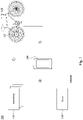
- Fig. 1 is a schematic diagram of a vehicle safety system 100 according to some embodiments of the present disclosure.
- the vehicle safety system 100 includes a server 110, a communication module 121, and at least one accessory 130.
- the server 110 is configured to communicate with a remote device 140 (e.g., a smart phone, a smart wearable device, or other portable device) held by a user.
- a remote device 140 e.g., a smart phone, a smart wearable device, or other portable device
- the user may wirelessly communicate with the server 110 by an application program operating on the remote device 140 through Internet. Data associated with the remote device 140 may be stored in the server 110.
- the communication module 121 is configured to communicate with the remote device 140 through a short-distance transmission protocol (e.g., Bluetooth or Wi-Fi module), and may be directly installed on a vehicle 120 or may be attached to any one of components on the vehicle 120.
- the accessory 130 is also configured to communicate with the remote device 140 through the short-distance transmission protocol.
- the communication module 121 and the accessory 130 are configured to communicate with each other through the short-distance transmission protocol.
- the vehicle 120 is an electric car, scooter, or bicycle, but the disclosure is not limited in this regard.
- the communication module 121 may be a hub device installed on the rear wheel of the vehicle 120, but the disclosure is not limited in this regard.
- the accessory 130 may be a handlebar detachably installed on the vehicle 120, but the disclosure is not limited in this regard. In some other embodiments, the accessory 130 may be a smart helmet or other personal wear parts.
- the wireless data connection (such as the connection C as shown in Fig. 1 ) between the communication module 121 and the accessory 130 may be established through the remote device 140.
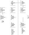
- Fig. 2 is a flowchart of establishing the wireless data connection between the communication module 121 and the accessory 130 according to some embodiments of the present disclosure. As shown in Fig. 2 with reference to Fig. 1 , the flowchart includes steps S11-S16.
- step S11 a connection A is established between the remote device 140 and the communication module 121.
- connection A is certificated.
- data such as a string of characters or a certification key
- the connection A may be transferred to the server 110 through the remote device 140 and stored in the server 110.
- Fig. 3 is a schematic diagram showing a certification procedure according to some embodiments of the present disclosure.
- the certification of the connection A may be initiated by the remote device 140 (e.g., via an App installed therein).
- the remote device 140 may request a random number from the communication module 121 (e.g., the hub device).
- the communication module 121 may provide the random number as requested (block 21), and the remote device 140 may transfer the provided random number to the server 110 (block 22).
- the server 110 is configured to create a temporary key in response to receiving of the random number (block 24) and provide the temporary key to the communication module 121 via the remote device 140 (block 25).
- the communication module 121 is configured to verify the temporary key with a built-in authentication code pre-stored in the communication module 121 (block 26). When the temporary key matches the built-in authentication code, the certification procedure of the connection A is certificated (block 28, i.e., confirmed as successful), and the temporary key may be then stored in the remote device 140 (block 28).
- step S13 a connection B is established between the remote device 140 and the accessory 130.
- the certification of the connection B may be performed by the server 110, the remote device 140, and the accessory 130 in a manner similar to the certification procedure among the server 110, the remote device 140, and the communication module 121, but the disclosure is not limited in this regard.
- step S14 the connection B is certificated.
- data associated with the certification of the connection B may be transferred to the server 110 through the remote device 140 and stored in the server 110.
- step S15 a connection C is established between the communication module 121 and the accessory 130.
- connection C may be initiated by the remote device 140 via the connection A or the connection B. In some embodiments, only when the connection A and connection B are established, the remote device 140 can start the process of establishing the connection C. In some embodiments, the process of establishing the connection C can be executed automatically or manually.
- step S16 the connection C is certificated.
- data associated with the certification of the connection C may be transferred to the server 110 through the remote device 140 and stored in the server 110.
- the certification of the connection C may be performed by the accessory 130, the remote device 140, and the communication module 121 in a manner similar to the certification procedure among the server 110, the remote device 140, and the communication module 121, but the disclosure is not limited in this regard.
- the communication module 121 and the accessory 130 can be automatically connected after booting without going through the remote device 140.
- the vehicle safety system 100 can at least perform following applications (1)-(4).
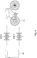
- Fig. 4 is a schematic diagram showing signal transmission between the remote device 140 of the user and the communication module 121 attached to the vehicle 120.
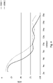
- Fig. 6 shows RSSI-distance (Received Signal Strength Indicator-distance) curves according to some embodiments of the present disclosure. It should be pointed out that at least for the purpose of automatically locking/unlocking the vehicle 120, it is extremely important to accurately determine the distance between the remote device 140 of the user and the vehicle 120. In order to improve the accuracy of distance determination, two-way RSSI is adopted.
- the communication module 121 is configured to detect RSSI 1 of the remote device 140
- the remote device 140 is configured to detect RSSI 2 of the communication module 121.
- Fig. 5 is a flowchart of a distance determination method according to some embodiments of the present disclosure. As shown in Fig. 5 , the distance determination method may include steps S21-S25.
- the remote device 140 (first electronic device) and the communication module 121 (second electronic device) send wireless signals to each other or broadcast the wireless signals.
- the remote device 140 may be replaced with the accessory 130 (such as a smart key), and the method may determine a distance of the accessory 130 and the communication module 121.
- step S21 RSSI 2 (second RSSI) of the wireless signal sent from the communication module 121 is detected by the remote device 140.
- step S22 RSSI 1 (first RSSI) of the wireless signal sent from the remote device 140 is detected by the communication module 121.
- step S23 RSSI 1 is obtained by the remote device 140 from the communication module 121, and RSSI 2 is obtained by the communication module 121 from the remote device 140.
- step S24 the motion direction and the distance of the remote device 140 relative to the communication module 121 is calculated by at least one of the remote device 140 and the remote device 140.
- the remote device 140 is configured to calibrate the motion direction and the distance based on RSSI 2 with reference to RSSI 1.
- the communication module 121 is configured to calibrate the motion direction and the distance based on RSSI 1 with reference to RSSI 2.
- a process of certification is started.
- the process of certification is started when the distance matches with a default condition.
- the default condition may include at least one of: the distance remaining the same or continuing to decrease; the distance being less than a threshold distance (such as 300 centimeters); and the distance being within a threshold distance range (such as 10-200 centimeters).
- the purpose of automatically locking/unlocking the vehicle 120 can be accurately achieved based on the calibrated motion direction and distance.
- data of RSSI 1 curve (such as a relationship obtained by test of RSSI 1 value and distance) for the remote device 140 is stored in the remote device 140 in advance
- data of RSSI 2 curve (such as a relationship obtained by test of RSSI 2 value and distance) for the communication module 121 is stored in the communication module 121 in advance.
- the remote device 140 and the communication module 121 may exchange their RSSI curves after the connection between them is established.
- both the remote device 140 and the communication module 121 have the data of RSSI 1 curve and data of RSSI 2 curve.
- the remote device 140 and the communication module 121 may determine the RSSI 1 distance based on the current RSSI 1 and the RSSI 1 curve, and determine the RSSI 2 distance based on the current RSSI 2 and the RSSI 2 curve.
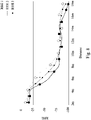
- Fig. 7 shows a RSSI-distance curve after compensation according to some embodiments of the present disclosure.
- the compensation refers to the calibration of RSSI described hereafter.
- calibrated RSSI 3 is obtained by equation 1.
- RSSI 3 RSSI 1 + RSSI 2 / 2
- RSSI-distance curve of RSSI 3 can be obtained by directly averaging the RSSI-distance curves of RSSI 1 and RSSI 2, but the disclosure is not limited in this regard.
- RSSI 1 and RSSI 2 may be respectively assigned the different average weights.
- Fig. 8 shows a RSSI-distance curve after compensation according to some embodiments of the present disclosure.
- the RSSI-distance curves of the two can be used to resample and reconstruct the RSSI-distance curve of RSSI 3.
- a distance of the remote device 140 and the communication module 121 is increased from 2 meters to 18 meters.
- both the RSSI 1 and RSSI 2 are sampled for calculating the RSSI 3.
- only the RSSI 1 is sampled for calculating the RSSI 3.
- the RSSI 2 is sampled for calculating the RSSI 3.
- both the RSSI 1 and RSSI 2 are sampled for calculating the RSSI 3.
- RSSI 1 and RSSI 2 may be sampled simultaneously or not.
- sampling times of the RSSI-distance curves of RSSI 1 and RSSI 2 may be different.
- data that is too peculiar and unreasonable in the RSSI-distance curves of RSSI 1 and RSSI 2 can be filtered out, which can effectively increase the accuracy of the reconstructed RSSI-distance curve of RSSI 3.
- the distance determination method by using the distance determination method, the shortcoming of insufficient positioning of the vehicle 120 can be improved. In some practical applications, by using the distance determination method, the shortcoming of starting the vehicle 120 based on an inaccurate distance can be improved.
- Fig. 9 is a schematic diagram of the vehicle 120 according to some embodiments of the present disclosure.
- the vehicle 120 can be equipped with a bag 131 and a PDC (Power delivery charger) 132.
- the bag 131 may be tied on the vehicle 120.
- the vehicle 120 may be an electric bicycle, and the bag 131 may be tied on the frame 122 of the vehicle 120.
- the PDC 132 is accommodated in the bag 131.
- the PDC 132 may be a charger using common USB type C connector and USB PD protocol as an energy source.
- the PDC 132 is connected to a charging connector of the communication module 121, so as to supply power to the communication module 121.
- the communication module 121 is a hub device installed on the rear wheel of the vehicle 120, and is configured to provide auxiliary power to turn the rear wheel.
- the user can use his/her USB PD charger or USB-PD power bank to supply power to the PDC 132.
- the power bank can be used as a source of electrical energy, the vehicle 120 can be charged anytime and anywhere during the commute.
- the PDC 132 conforms to the USB PD protocol, no dedicate charger is needed anymore.
- the vehicle 120 can be charged during riding.
- the cost of maintaining the vehicle 120 by the service provider can be reduced.
- the service provider can give the customer some preferential discounts.
- the vehicle 120 is in an environment around zero degrees, immediately starting and riding the vehicle 120 may be limited by the low temperature of the built-in battery and poor discharge performance. If the user can carry the power bank from a 20 degree indoor environment to the vehicle 120 and start the vehicle 120, in addition to providing power, the power bank can also make the built-in battery heat up while the power is flowing to the built-in battery.
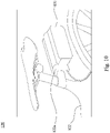
- Fig. 10 is a partial schematic diagram of the vehicle 120 according to some embodiments of the present disclosure.
- a hard housing 122a is mounted onto the frame 122, and the bag 131 hangs on the hard housing 122a.
- the hard housing 122a may be located under the seat cushion and extend toward the rear of the vehicle 120 above the rear wheel thereof.
- the circuit board of the PDC 132 may be accommodated in the hard housing 122a. Additional power banks may be accommodated in the bag 131.
- the hard housing 122a may be detachably fastened to the frame 122.
- the hard housing 122a may be an integrally-formed part of the frame 122.
- Fig. 11 is a partial schematic diagram of the vehicle 120 to some embodiments of the present disclosure.
- the frame 122 has an opening 122b at the bottom side and is hollow inside, and the PDC 132 is installed in the frame 122 from the opening.
- the opening 122b is sealed by a sealing member 123, so as to prevent the PDC 132 from falling out. That is, compared with the embodiment shown in Fig. 9 , the PDC 132 of the present embodiment is directly installed in the frame 122 of the vehicle 120.
- two-way RSSI is adopted, so that the distance between two electronic devices can be accurately determined.
- the two electronic devices are a remote device of a user and a communication module attached to a vehicle, at least the purpose of automatically locking/unlocking the vehicle with a better accuracy can be achieved based on the accurate distance determined by the distance determination method.
Landscapes
- Engineering & Computer Science (AREA)
- Computer Networks & Wireless Communication (AREA)
- Mechanical Engineering (AREA)
- Signal Processing (AREA)
- Physics & Mathematics (AREA)
- General Physics & Mathematics (AREA)
- Radar, Positioning & Navigation (AREA)
- Remote Sensing (AREA)
- Electromagnetism (AREA)
- Computer Security & Cryptography (AREA)
- Computer Hardware Design (AREA)
- Computing Systems (AREA)
- General Engineering & Computer Science (AREA)
- Human Computer Interaction (AREA)
- Lock And Its Accessories (AREA)
- Radar Systems Or Details Thereof (AREA)
- Position Fixing By Use Of Radio Waves (AREA)
- Quality & Reliability (AREA)
- Length Measuring Devices With Unspecified Measuring Means (AREA)
- Arrangement Or Mounting Of Propulsion Units For Vehicles (AREA)
Abstract
Description
- The present disclosure relates to a vehicle safety system, a distance determination method, and a vehicle.
- In order to automatically lock/unlock a vehicle, the distance between the vehicle and a remote device of a user (e.g., such as a key thereof) need to be accurately determined. In the related art, a distance determination method of determining the distance between the remote device and the vehicle is detecting the RSSI (Received Signal Strength Indicator) of a wireless signal sent from the remote device to the vehicle and calculating the distance by using only the single RSSI. However, the distance determination method often cannot accurately determine the position and distance of the remote device relative to the vehicle, so the vehicle may lock/unlock based on inaccurate distance.
- Accordingly, how to provide a distance determination method that can solve the aforementioned problems becomes an important issue to be solved by those in the industry.
- An aspect of the disclosure is to provide a distance determination method that can efficiently solve the aforementioned problems.
- According to an embodiment of the disclosure, a distance determination method includes: detecting a first received signal strength indicator (RSSI) of a first electronic device by a second electronic device; detecting a second RSSI of the second electronic device by the first electronic device; obtaining the first RSSI from the second electronic device by the first electronic device; and calculating a motion direction and a distance of the second electronic device relative to the first electronic device according to the first RSSI and the second RSSI by the first electronic device.
- In an embodiment of the disclosure, the calculating includes calibrating the motion direction and the distance based on the second RSSI with reference to the first RSSI by the first electronic device.
- In an embodiment of the disclosure, the distance determination method further includes obtaining the second RSSI from the first electronic device by the second electronic device. The calculating includes calibrating the motion direction and the distance based on the first RSSI with reference to the second RSSI by the second electronic device.
- In an embodiment of the disclosure, one of the first electronic device and the second electronic device is a remote device or an accessory. Another of the first electronic device and the second electronic device is a communication module attached to a vehicle.
- In an embodiment of the disclosure, the distance determination method further includes automatically locking/unlocking the vehicle based on the motion direction and the distance.
- In an embodiment of the disclosure, the distance determination method further includes: establishing a first connection between the remote device the communication module; establishing a second connection between the remote device the accessory; and establishing a third connection based on the first connection and the second connection.
- In an embodiment of the disclosure, the distance determination method further includes certificating the first connection. The certificating includes: requesting a random number from the communication module by the remote device; providing the random number to the remote device by the communication module; transferring the random number to a server by the remote device; creating a temporary key by the server in response to receiving of the random number; providing the temporary key to the communication module via the remote device by the server; and verifying the temporary key with a built-in authentication code pre-stored in the communication module by the communication module.
- In an embodiment of the disclosure, the calculating includes averaging the first RSSI and the second RSSI.
- In an embodiment of the disclosure, the distance determination method further includes: retrieving a first RSSI-distance curve of the first RSSI; retrieving a second RSSI-distance curve of the second RSSI; and calculating a third RSSI-distance curve based on the first RSSI-distance curve and the second RSSI-distance curve. The calculating includes calculating the motion direction and the distance based on the third RSSI-distance curve.
- In an embodiment of the disclosure, the calculating the third RSSI-distance curve includes at least one of: averaging the first RSSI-distance curve and the second RSSI-distance curve; calculating the third RSSI-distance curve by resampling the first RSSI-distance curve and the second RSSI-distance curve at different sampling distances; and calculating the third RSSI-distance curve by iteratively resampling the first RSSI-distance curve and the second RSSI-distance curve as sampling distance changes.
- According to an embodiment of the disclosure, a vehicle includes a frame, a communication module, and communication module. The communication module is fixed on the frame and includes a charging connector. The power delivery charger is fixed to the frame, is detachably connected to the charging connector, and is configured to supply power to the communication module via the charging connector.
- In an embodiment of the disclosure, the vehicle further includes a bag tied on the frame. The power delivery charger is accommodated in the bag.
- In an embodiment of the disclosure, the vehicle further includes a rear wheel rotatably connected to the frame. The communication module is a hub device installed on the rear wheel.
- In an embodiment of the disclosure, the vehicle further includes a hard housing and a bag. The hard housing is connected to the frame. The bag hangs on the hard housing. The power delivery charger is accommodated in the bag.
- In an embodiment of the disclosure, the vehicle further includes a rear wheel and a seat cushion. The rear wheel is rotatably connected to the frame. The seat cushion is connected to the frame. The hard housing is located under the seat cushion and extends toward the rear of the vehicle above the rear wheel.
- In an embodiment of the disclosure, the frame has an opening at a bottom side thereof and is hollow inside. The power delivery charger is accommodated in the frame. The opening is configured to allow the power delivery charger to pass through.
- In an embodiment of the disclosure, the vehicle further includes a sealing member sealing the opening.
- According to another embodiment of the disclosure, a distance determination method includes: plotting a first RSSI-distance curve of a first RSSI of a first electronic device; plotting a second RSSI-distance curve of a second RSSI of a second electronic device; plotting a third RSSI-distance curve based on the first RSSI-distance curve and the second RSSI-distance curve; and calculating a motion direction and a distance of the second electronic device relative to the first electronic device based on the third RSSI-distance curve.
- In an embodiment of the disclosure, one of the first electronic device and the second electronic device is a remote device of a user. Another of the first electronic device and the second electronic device is a communication module attached to a vehicle of the user.
- In an embodiment of the disclosure, the distance determination method further includes automatically locking/unlocking the vehicle based on the motion direction and the distance.
- In an embodiment of the disclosure, the plotting the third RSSI-distance curve includes plotting the third RSSI-distance curve based on by averaging the first RSSI-distance curve and the second RSSI-distance curve.
- In an embodiment of the disclosure, the plotting the third RSSI-distance curve includes plotting the third RSSI-distance curve by resampling the first RSSI-distance curve and the second RSSI-distance curve.
- In an embodiment of the disclosure, the plotting the third RSSI-distance curve further includes plotting the third RSSI-distance curve by resampling the first RSSI-distance curve and the second RSSI-distance curve at different sampling distances.
- In an embodiment of the disclosure, the plotting the third RSSI-distance curve further includes plotting the third RSSI-distance curve by iteratively resampling the first RSSI-distance curve and the second RSSI-distance curve as sampling distance changes.
- Accordingly, in the distance determination method of the present disclosure, two-way RSSI is adopted, so that the distance between two electronic devices can be accurately determined. In this way, by using the distance determination method in the embodiments that the two electronic devices are a remote device of a user and a communication module attached to a vehicle, at least the purpose of automatically locking/unlocking the vehicle with a better accuracy can be achieved based on the accurate distance determined by the distance determination method.
- It is to be understood that both the foregoing general description and the following detailed description are by examples, and are intended to provide further explanation of the disclosure as claimed.
- The disclosure can be more fully understood by reading the following detailed description of the embodiment, with reference made to the accompanying drawings as follows:
-
Fig. 1 is a schematic diagram of a vehicle safety system according to some embodiments of the present disclosure; -
Fig. 2 is a flowchart of establishing the wireless data connection between the communication module and the accessory according to some embodiments of the present disclosure; -
Fig. 3 is a schematic diagram showing a certification procedure according to some embodiments of the present disclosure; -
Fig. 4 is a schematic diagram showing signal transmission between a remote device of a user and a communication module attached to a vehicle; -
Fig. 5 is a flowchart of a distance determination method according to some embodiments of the present disclosure; -
Fig. 6 shows RSSI-distance curves according to some embodiments of the present disclosure; -
Fig. 7 shows a RSSI-distance curve after compensation according to some embodiments of the present disclosure; -
Fig. 8 shows a RSSI-distance curve after compensation according to some embodiments of the present disclosure; -
Fig. 9 is a schematic diagram of a vehicle according to some embodiments of the present disclosure; -
Fig. 10 is a partial schematic diagram of the vehicle according to some embodiments of the present disclosure; and -
Fig. 11 is a partial schematic diagram of the vehicle to some embodiments of the present disclosure. - Reference will now be made in detail to the present embodiments of the disclosure, examples of which are illustrated in the accompanying drawings. Wherever possible, the same reference numbers are used in the drawings and the description to refer to the same or like parts. However, specific structural and functional details disclosed herein are merely representative for purposes of describing example embodiments, and thus may be embodied in many alternate forms and should not be construed as limited to only example embodiments set forth herein. Therefore, it should be understood that there is no intent to limit example embodiments to the particular forms disclosed, but on the contrary, example embodiments are to cover all modifications, equivalents, and alternatives falling within the scope of the disclosure.
- Reference is made to
Fig. 1. Fig. 1 is a schematic diagram of avehicle safety system 100 according to some embodiments of the present disclosure. As shown inFig. 1 , in the present embodiment, thevehicle safety system 100 includes aserver 110, acommunication module 121, and at least oneaccessory 130. Theserver 110 is configured to communicate with a remote device 140 (e.g., a smart phone, a smart wearable device, or other portable device) held by a user. For example, the user may wirelessly communicate with theserver 110 by an application program operating on theremote device 140 through Internet. Data associated with theremote device 140 may be stored in theserver 110. Thecommunication module 121 is configured to communicate with theremote device 140 through a short-distance transmission protocol (e.g., Bluetooth or Wi-Fi module), and may be directly installed on avehicle 120 or may be attached to any one of components on thevehicle 120. Theaccessory 130 is also configured to communicate with theremote device 140 through the short-distance transmission protocol. In addition, thecommunication module 121 and theaccessory 130 are configured to communicate with each other through the short-distance transmission protocol. - In some embodiments, the
vehicle 120 is an electric car, scooter, or bicycle, but the disclosure is not limited in this regard. - In some embodiments, the
communication module 121 may be a hub device installed on the rear wheel of thevehicle 120, but the disclosure is not limited in this regard. - In some embodiments, the
accessory 130 may be a handlebar detachably installed on thevehicle 120, but the disclosure is not limited in this regard. In some other embodiments, theaccessory 130 may be a smart helmet or other personal wear parts. - Under the architecture of the
vehicle safety system 100, in some embodiments, the wireless data connection (such as the connection C as shown inFig. 1 ) between thecommunication module 121 and theaccessory 130 may be established through theremote device 140. - Reference is made to
Fig. 2. Fig. 2 is a flowchart of establishing the wireless data connection between thecommunication module 121 and theaccessory 130 according to some embodiments of the present disclosure. As shown inFig. 2 with reference toFig. 1 , the flowchart includes steps S11-S16. - In step S11, a connection A is established between the
remote device 140 and thecommunication module 121. - In step S12, the connection A is certificated. For example, data (such as a string of characters or a certification key) associated with the certification of the connection A may be transferred to the
server 110 through theremote device 140 and stored in theserver 110. - Reference is made to
Fig. 3. Fig. 3 is a schematic diagram showing a certification procedure according to some embodiments of the present disclosure. As shown inFig. 3 , the certification of the connection A may be initiated by the remote device 140 (e.g., via an App installed therein). In the beginning (block 20), theremote device 140 may request a random number from the communication module 121 (e.g., the hub device). Thecommunication module 121 may provide the random number as requested (block 21), and theremote device 140 may transfer the provided random number to the server 110 (block 22). Theserver 110 is configured to create a temporary key in response to receiving of the random number (block 24) and provide the temporary key to thecommunication module 121 via the remote device 140 (block 25). Thecommunication module 121 is configured to verify the temporary key with a built-in authentication code pre-stored in the communication module 121 (block 26). When the temporary key matches the built-in authentication code, the certification procedure of the connection A is certificated (block 28, i.e., confirmed as successful), and the temporary key may be then stored in the remote device 140 (block 28). - In step S13, a connection B is established between the
remote device 140 and theaccessory 130. - In some embodiments, the certification of the connection B may be performed by the
server 110, theremote device 140, and theaccessory 130 in a manner similar to the certification procedure among theserver 110, theremote device 140, and thecommunication module 121, but the disclosure is not limited in this regard. - In step S14, the connection B is certificated. For example, data associated with the certification of the connection B may be transferred to the
server 110 through theremote device 140 and stored in theserver 110. - In step S15, a connection C is established between the
communication module 121 and theaccessory 130. - In some embodiments, the connection C may be initiated by the
remote device 140 via the connection A or the connection B. In some embodiments, only when the connection A and connection B are established, theremote device 140 can start the process of establishing the connection C. In some embodiments, the process of establishing the connection C can be executed automatically or manually. - In step S16, the connection C is certificated. For example, data associated with the certification of the connection C may be transferred to the
server 110 through theremote device 140 and stored in theserver 110. - In some embodiments, the certification of the connection C may be performed by the
accessory 130, theremote device 140, and thecommunication module 121 in a manner similar to the certification procedure among theserver 110, theremote device 140, and thecommunication module 121, but the disclosure is not limited in this regard. - In some embodiments, once the connection C are established for the first time, the
communication module 121 and theaccessory 130 can be automatically connected after booting without going through theremote device 140. - With the aforementioned configurations, the
vehicle safety system 100 can at least perform following applications (1)-(4). - (1) When the
communication module 121 or theaccessory 130 detects illegal starting or moving of thevehicle 120, measures such as locking thevehicle 120 are taken. In some embodiments, the illegal starting or moving of thevehicle 120 may be identified when the certificated connection C between thecommunication module 121 and theaccessory 130 is not available after they are booted. In some embodiments, the illegal starting or moving of thevehicle 120 may identified when the GPS data detected by thecommunication module 121 and/or theaccessory 130 have changed after they are booted. - (2) After the
vehicle 120 is reported lost, the log data during the lost time period can be read as evidence. - (3) In the scenario where the
vehicle 120 can be rented, the user can select at least one of a plurality ofaccessories 130 to connect it via theremote device 140, thus increasing the flexibility of the renting service of thevehicle 120. - (4) In the scenario where the
accessory 130 is a handlebar and theremote device 140 is a smart phone equipped with sensors (e.g., a gyro sensor, an accelerometer, etc.), data detected by the sensors may be provided to the handlebar for automatic start of direction lights or automatic shutdown for power saving. In addition, the handlebar may obtain information (e.g., power state of battery, temperature of battery, etc.) of thevehicle 120 through thecommunication module 121, display the information, and even use lights to remind user (e.g., indicating low power, overheat protection, etc.) according to the information. - Reference is made to
Figs. 4 and6 .Fig. 4 is a schematic diagram showing signal transmission between theremote device 140 of the user and thecommunication module 121 attached to thevehicle 120.Fig. 6 shows RSSI-distance (Received Signal Strength Indicator-distance) curves according to some embodiments of the present disclosure. It should be pointed out that at least for the purpose of automatically locking/unlocking thevehicle 120, it is extremely important to accurately determine the distance between theremote device 140 of the user and thevehicle 120. In order to improve the accuracy of distance determination, two-way RSSI is adopted. In some embodiments, thecommunication module 121 is configured to detectRSSI 1 of theremote device 140, and theremote device 140 is configured to detectRSSI 2 of thecommunication module 121. - Reference is made to
Fig. 5. Fig. 5 is a flowchart of a distance determination method according to some embodiments of the present disclosure. As shown inFig. 5 , the distance determination method may include steps S21-S25. - In the beginning, the remote device 140 (first electronic device) and the communication module 121 (second electronic device) send wireless signals to each other or broadcast the wireless signals.
- In some embodiments, the
remote device 140 may be replaced with the accessory 130 (such as a smart key), and the method may determine a distance of theaccessory 130 and thecommunication module 121. - In step S21, RSSI 2 (second RSSI) of the wireless signal sent from the
communication module 121 is detected by theremote device 140. - In step S22, RSSI 1 (first RSSI) of the wireless signal sent from the
remote device 140 is detected by thecommunication module 121. - In step S23,
RSSI 1 is obtained by theremote device 140 from thecommunication module 121, andRSSI 2 is obtained by thecommunication module 121 from theremote device 140. - In step S24, the motion direction and the distance of the
remote device 140 relative to thecommunication module 121 is calculated by at least one of theremote device 140 and theremote device 140. - In some embodiments, the
remote device 140 is configured to calibrate the motion direction and the distance based onRSSI 2 with reference toRSSI 1. In some embodiments, thecommunication module 121 is configured to calibrate the motion direction and the distance based onRSSI 1 with reference toRSSI 2. - In step S25, a process of certification is started. In some embodiments, the process of certification is started when the distance matches with a default condition. In some embodiments, the default condition may include at least one of: the distance remaining the same or continuing to decrease; the distance being less than a threshold distance (such as 300 centimeters); and the distance being within a threshold distance range (such as 10-200 centimeters).
- After performing the distance determination introduced above, the purpose of automatically locking/unlocking the
vehicle 120 can be accurately achieved based on the calibrated motion direction and distance. - In some embodiments, data of
RSSI 1 curve (such as a relationship obtained by test ofRSSI 1 value and distance) for theremote device 140 is stored in theremote device 140 in advance, and data ofRSSI 2 curve (such as a relationship obtained by test ofRSSI 2 value and distance) for thecommunication module 121 is stored in thecommunication module 121 in advance. Theremote device 140 and thecommunication module 121 may exchange their RSSI curves after the connection between them is established. Thus, both theremote device 140 and thecommunication module 121 have the data ofRSSI 1 curve and data ofRSSI 2 curve. After the exchange ofRSSI 1 curve andRSSI 2 curve, theremote device 140 and thecommunication module 121 may determine theRSSI 1 distance based on thecurrent RSSI 1 and theRSSI 1 curve, and determine theRSSI 2 distance based on thecurrent RSSI 2 and theRSSI 2 curve. - Reference is made to
Fig. 7. Fig. 7 shows a RSSI-distance curve after compensation according to some embodiments of the present disclosure. The compensation refers to the calibration of RSSI described hereafter. As shown inFig. 7 , calibratedRSSI 3 is obtained byequation 1.
- It can be seen that the RSSI-distance curve of
RSSI 3 can be obtained by directly averaging the RSSI-distance curves ofRSSI 1 andRSSI 2, but the disclosure is not limited in this regard. In some embodiments,RSSI 1 andRSSI 2 may be respectively assigned the different average weights. For example, theequation 1 may be modified to "RSSI 3 = 0.4*RSSI 1 + 0.6*RSSI 2". - Reference is made to
Fig. 8. Fig. 8 shows a RSSI-distance curve after compensation according to some embodiments of the present disclosure. When the difference betweenRSSI 1 andRSSI 2 is large, the RSSI-distance curves of the two can be used to resample and reconstruct the RSSI-distance curve ofRSSI 3. For example, a distance of theremote device 140 and thecommunication module 121 is increased from 2 meters to 18 meters. In the first timepoint (2m), both theRSSI 1 andRSSI 2 are sampled for calculating theRSSI 3. In the second timepoint, only theRSSI 1 is sampled for calculating theRSSI 3. In the third timepoint, only theRSSI 2 is sampled for calculating theRSSI 3. In the last timepoint (18m), both theRSSI 1 andRSSI 2 are sampled for calculating theRSSI 3. In this example,RSSI 1 andRSSI 2 may be sampled simultaneously or not. Thus, sampling times of the RSSI-distance curves ofRSSI 1 andRSSI 2 may be different. As such, data that is too peculiar and unreasonable in the RSSI-distance curves ofRSSI 1 andRSSI 2 can be filtered out, which can effectively increase the accuracy of the reconstructed RSSI-distance curve ofRSSI 3. - In some practical applications, by using the distance determination method, the shortcoming of insufficient positioning of the
vehicle 120 can be improved. In some practical applications, by using the distance determination method, the shortcoming of starting thevehicle 120 based on an inaccurate distance can be improved. - Reference is made to
Fig. 9. Fig. 9 is a schematic diagram of thevehicle 120 according to some embodiments of the present disclosure. As shown inFig. 9 , in the present embodiment, thevehicle 120 can be equipped with abag 131 and a PDC (Power delivery charger) 132. Thebag 131 may be tied on thevehicle 120. For example, thevehicle 120 may be an electric bicycle, and thebag 131 may be tied on theframe 122 of thevehicle 120. ThePDC 132 is accommodated in thebag 131. ThePDC 132 may be a charger using common USB type C connector and USB PD protocol as an energy source. - In some embodiments, the
PDC 132 is connected to a charging connector of thecommunication module 121, so as to supply power to thecommunication module 121. In some embodiments, thecommunication module 121 is a hub device installed on the rear wheel of thevehicle 120, and is configured to provide auxiliary power to turn the rear wheel. In some embodiments, the user can use his/her USB PD charger or USB-PD power bank to supply power to thePDC 132. - In some practical application, since the power bank can be used as a source of electrical energy, the
vehicle 120 can be charged anytime and anywhere during the commute. In some practical applications, since thePDC 132 conforms to the USB PD protocol, no dedicate charger is needed anymore. In some practical application, with thePDC 132, thevehicle 120 can be charged during riding. In some practical application, when a customer rents thevehicle 120 and charges thevehicle 120 with its own power bank, the cost of maintaining thevehicle 120 by the service provider can be reduced. At the same time, the service provider can give the customer some preferential discounts. In some practical application, when thevehicle 120 is in an environment around zero degrees, immediately starting and riding thevehicle 120 may be limited by the low temperature of the built-in battery and poor discharge performance. If the user can carry the power bank from a 20 degree indoor environment to thevehicle 120 and start thevehicle 120, in addition to providing power, the power bank can also make the built-in battery heat up while the power is flowing to the built-in battery. - Reference is made to
Fig. 10. Fig. 10 is a partial schematic diagram of thevehicle 120 according to some embodiments of the present disclosure. As shown inFig. 10 , ahard housing 122a is mounted onto theframe 122, and thebag 131 hangs on thehard housing 122a. Thehard housing 122a may be located under the seat cushion and extend toward the rear of thevehicle 120 above the rear wheel thereof. The circuit board of thePDC 132 may be accommodated in thehard housing 122a. Additional power banks may be accommodated in thebag 131. In some embodiment, thehard housing 122a may be detachably fastened to theframe 122. In some other embodiment, thehard housing 122a may be an integrally-formed part of theframe 122. - Reference is made to
Fig. 11. Fig. 11 is a partial schematic diagram of thevehicle 120 to some embodiments of the present disclosure. As shown inFig. 11 , in the present embodiment, theframe 122 has anopening 122b at the bottom side and is hollow inside, and thePDC 132 is installed in theframe 122 from the opening. Theopening 122b is sealed by a sealingmember 123, so as to prevent thePDC 132 from falling out. That is, compared with the embodiment shown inFig. 9 , thePDC 132 of the present embodiment is directly installed in theframe 122 of thevehicle 120. - According to the foregoing recitations of the embodiments of the disclosure, it can be seen that in the distance determination method of the present disclosure, two-way RSSI is adopted, so that the distance between two electronic devices can be accurately determined. In this way, by using the distance determination method in the embodiments that the two electronic devices are a remote device of a user and a communication module attached to a vehicle, at least the purpose of automatically locking/unlocking the vehicle with a better accuracy can be achieved based on the accurate distance determined by the distance determination method.
Claims (17)
- A distance determination method, characterized by comprising:detecting a first RSSI (RSSI 1) of a first electronic device by a second electronic device (S21);detecting a second RSSI (RSSI 2) of the second electronic device by the first electronic device (S22);obtaining the first RSSI (RSSI 1) from the second electronic device by the first electronic device (S23); andcalculating a motion direction and a distance of the second electronic device relative to the first electronic device according to the first RSSI (RSSI 1) and the second RSSI (RSSI 2) by the first electronic device (S24).
- The distance determination method of claim 1, wherein the calculating comprises:
calibrating the motion direction and the distance based on the second RSSI (RSSI 2) with reference to the first RSSI (RSSI 1) by the first electronic device. - The distance determination method of any preceding claim, further comprising:obtaining the second RSSI (RSSI 2) from the first electronic device by the second electronic device,wherein the calculating comprises:
calibrating the motion direction and the distance based on the first RSSI (RSSI 1) with reference to the second RSSI (RSSI 1) by the second electronic device. - The distance determination method of any preceding claim, wherein one of the first electronic device and the second electronic device is a remote device or an accessory, and another of the first electronic device and the second electronic device is a communication module attached to a vehicle.
- The distance determination method of claim 4, further comprising:
automatically locking/unlocking the vehicle based on the motion direction and the distance. - The distance determination method of claim 4, further comprising:establishing a first connection between the remote device the communication module (S11);establishing a second connection between the remote device the accessory (S13); andestablishing a third connection based on the first connection and the second connection (S15).
- The distance determination method of claim 6, further comprising certificating the first connection, wherein the certificating comprises:requesting a random number from the communication module by the remote device (20);providing the random number to the remote device by the communication module (21);transferring the random number to a server by the remote device (22);creating a temporary key by the server in response to receiving of the random number (24);providing the temporary key to the communication module via the remote device by the server (25); andverifying the temporary key with a built-in authentication code pre-stored in the communication module by the communication module (26).
- The distance determination method of any preceding claim, wherein the calculating comprises:
averaging the first RSSI (RSSI 1) and the second RSSI (RSSI 2). - The distance determination method of any of claims 1-8, further comprising:retrieving a first RSSI-distance curve of the first RSSI (RSSI 1);retrieving a second RSSI-distance curve of the second RSSI (RSSI 2); andcalculating a third RSSI-distance curve based on the first RSSI-distance curve and the second RSSI-distance curve,wherein the calculating comprises calculating the motion direction and the distance based on the third RSSI-distance curve.
- The distance determination method of claim 9, wherein the calculating the third RSSI-distance curve comprises at least one of:averaging the first RSSI-distance curve and the second RSSI-distance curve;calculating the third RSSI-distance curve by resampling the first RSSI-distance curve and the second RSSI-distance curve at different sampling distances; andcalculating the third RSSI-distance curve by iteratively resampling the first RSSI-distance curve and the second RSSI-distance curve as sampling distance changes.
- A vehicle (120), comprising:a frame (122);a communication module (121) fixed on the frame (122) and comprising a charging connector; anda power delivery charger (132) fixed to the frame (122), detachably connected to the charging connector, and configured to supply power to the communication module (121) via the charging connector.
- The vehicle (120) of claim 11, further comprising a bag (131) tied on the frame (122), wherein the power delivery charger (132) is accommodated in the bag (131).
- The vehicle (120) of any preceding claim, further comprising a rear wheel rotatably connected to the frame (122), wherein the communication module (121) is a hub device installed on the rear wheel.
- The vehicle (120) of claim 11, further comprising:a hard housing (122a) connected to the frame (122); anda bag (131) hanging on the hard housing (122a), wherein the power delivery charger (132) is accommodated in the bag (131).
- The vehicle (120) of claim 14, further comprising:a rear wheel rotatably connected to the frame (122); anda seat cushion connected to the frame (122), wherein the hard housing (122a) is located under the seat cushion and extends toward the rear of the vehicle (120) above the rear wheel.
- The vehicle (120) of claim 11, wherein the frame (122) has an opening (122b) at a bottom side thereof and is hollow inside, the power delivery charger (132) is accommodated in the frame (122), and the opening (122b) is configured to allow the power delivery charger (132) to pass through.
- The vehicle (120) of claim 16, further comprising a sealing member (123) sealing the opening (122b).
Applications Claiming Priority (1)
| Application Number | Priority Date | Filing Date | Title |
|---|---|---|---|
| US202163212897P | 2021-06-21 | 2021-06-21 |
Publications (2)
| Publication Number | Publication Date |
|---|---|
| EP4109930A2 true EP4109930A2 (en) | 2022-12-28 |
| EP4109930A3 EP4109930A3 (en) | 2023-07-12 |
Family
ID=81940633
Family Applications (1)
| Application Number | Title | Priority Date | Filing Date |
|---|---|---|---|
| EP22176674.4A Withdrawn EP4109930A3 (en) | 2021-06-21 | 2022-06-01 | Distance determination method, and vehicle |
Country Status (7)
| Country | Link |
|---|---|
| US (1) | US12002313B2 (en) |
| EP (1) | EP4109930A3 (en) |
| JP (1) | JP2023001886A (en) |
| KR (1) | KR20220169903A (en) |
| CN (1) | CN115515071A (en) |
| PH (1) | PH12022050259A1 (en) |
| TW (2) | TWI814437B (en) |
Families Citing this family (2)
| Publication number | Priority date | Publication date | Assignee | Title |
|---|---|---|---|---|
| US12401525B2 (en) * | 2022-09-23 | 2025-08-26 | Toyota Motor North America, Inc. | Vehicle temporary certificate authentication |
| CN121604113A (en) * | 2026-01-30 | 2026-03-03 | 荣耀终端股份有限公司 | Wireless communication method and related device |
Family Cites Families (17)
| Publication number | Priority date | Publication date | Assignee | Title |
|---|---|---|---|---|
| JP2001128385A (en) | 1999-10-25 | 2001-05-11 | Yamaha Motor Co Ltd | Power supply system for electric vehicles |
| US8948782B2 (en) * | 2012-12-21 | 2015-02-03 | Qualcomm Incorporated | Proximity determination based on distance ratios |
| KR101530170B1 (en) * | 2013-09-17 | 2015-06-19 | 주식회사 만도 | Electric Bicycle |
| CN103971158B (en) * | 2014-04-25 | 2017-02-15 | 天津大学 | Temperature sensing label based on bidirectional RSSI positioning |
| US10019703B2 (en) * | 2014-05-13 | 2018-07-10 | Google Llc | Verifying a secure connection between a network beacon and a user computing device |
| CN104192227A (en) * | 2014-09-01 | 2014-12-10 | 录可系统公司 | Bicycle management system and method |
| JP6495783B2 (en) * | 2015-08-25 | 2019-04-03 | 太陽誘電株式会社 | Control device, power storage device and moving body |
| CN105398420B (en) * | 2015-11-09 | 2016-11-23 | 福建省汽车工业集团云度新能源汽车股份有限公司 | A kind of automotive keyless entering system detection method |
| US10039145B2 (en) * | 2015-11-19 | 2018-07-31 | Nike, Inc. | System, apparatus, and method for received signal strength indicator (RSSI) based authentication |
| CN111356814B (en) * | 2017-10-19 | 2022-06-07 | 株式会社电装 | Vehicle position determination system |
| CN107792007A (en) * | 2017-10-31 | 2018-03-13 | 北京新能源汽车股份有限公司 | Vehicle control system |
| CN110386105B (en) * | 2018-04-20 | 2021-05-14 | 比亚迪股份有限公司 | Vehicle unlocking method, system, mobile terminal and key controller |
| US10427643B1 (en) * | 2018-07-13 | 2019-10-01 | Nxp B.V. | Defense against relay attack in passive keyless entry systems |
| WO2020205364A1 (en) * | 2019-03-29 | 2020-10-08 | Denso International America, Inc. | Passive entry/passive start systems implementing music algorithm based angle of arrival determinations for signals received via circular polarized antennas |
| CN110228447B (en) * | 2019-06-14 | 2022-09-09 | 大陆投资(中国)有限公司 | Method and in-vehicle system for realizing keyless entry function of vehicle using smart antenna device |
| TWI699545B (en) * | 2019-06-14 | 2020-07-21 | 群光電子股份有限公司 | Electronic device, tracking system and tracking method |
| US11981181B2 (en) * | 2021-04-19 | 2024-05-14 | Apple Inc. | User interfaces for an electronic key |
-
2022
- 2022-06-01 EP EP22176674.4A patent/EP4109930A3/en not_active Withdrawn
- 2022-06-02 US US17/831,265 patent/US12002313B2/en active Active
- 2022-06-03 PH PH1/2022/050259A patent/PH12022050259A1/en unknown
- 2022-06-07 JP JP2022092332A patent/JP2023001886A/en not_active Withdrawn
- 2022-06-10 TW TW111121691A patent/TWI814437B/en active
- 2022-06-10 TW TW112120560A patent/TWI828592B/en active
- 2022-06-13 KR KR1020220071552A patent/KR20220169903A/en not_active Abandoned
- 2022-06-15 CN CN202210677236.3A patent/CN115515071A/en active Pending
Also Published As
| Publication number | Publication date |
|---|---|
| JP2023001886A (en) | 2023-01-06 |
| CN115515071A (en) | 2022-12-23 |
| TWI828592B (en) | 2024-01-01 |
| TW202300949A (en) | 2023-01-01 |
| US12002313B2 (en) | 2024-06-04 |
| US20220406109A1 (en) | 2022-12-22 |
| PH12022050259A1 (en) | 2023-03-27 |
| TWI814437B (en) | 2023-09-01 |
| EP4109930A3 (en) | 2023-07-12 |
| KR20220169903A (en) | 2022-12-28 |
| TW202336458A (en) | 2023-09-16 |
Similar Documents
| Publication | Publication Date | Title |
|---|---|---|
| US10761218B2 (en) | System for land vehicle navigation and corresponding method | |
| US20220406109A1 (en) | Vehicle safety system, distance determination method, and vehicle | |
| CN204694269U (en) | There is the code table of antitheft positioning function and the antitheft positioning system based on this code table | |
| KR101889635B1 (en) | Position measurement method, own position measurement device, and in-vehicle device | |
| US20090234599A1 (en) | System for recording charging-history of battery mounted on automotive vehicle | |
| EP2990571A1 (en) | System and method for managing bicycles, motorcycles and the like | |
| US20240176777A1 (en) | Systems and methods for updating electric charger locations | |
| WO2016145886A1 (en) | On board unit | |
| US20190232908A1 (en) | Systems and methods for accident management for vehicles | |
| CN115567892A (en) | A control method for shared motorcycles based on 4G intelligent central control device | |
| CN111947677A (en) | Shared vehicle positioning method and device | |
| JP5157795B2 (en) | Terminal positioning method, terminal positioning system, and base station | |
| CN105980884B (en) | Positioning terminal | |
| JP2010276411A (en) | Mobile terminal device | |
| CN107454569B (en) | A bicycle, cloud platform and method for calibrating position information of bicycle | |
| US11580594B2 (en) | Information processing device, information processing method, and information processing system | |
| KR101514540B1 (en) | App for Checking Tire Pressure | |
| WO2018009196A1 (en) | Systems, methods, and devices for data collection with removable battery with integrated storage | |
| WO2013160961A1 (en) | Theft detection reporting device and in-vehicle information device comprising same | |
| CN207502737U (en) | It is a kind of that there is the car-mounted terminal of Tail gas measuring | |
| NL2026892B1 (en) | Modular system for monitoring a velocipede | |
| CN116018528A (en) | Information processing method, information processing device, and information processing program | |
| KR20220071021A (en) | Method and System for Detecting Anomalous Usage of Vehicle by Subscriber of Per-Mile Car Insurance | |
| JP2003269990A (en) | Cellular telephone system with gps function, charging method for the system, and movable body position detecting method | |
| KR20190064781A (en) | System For Controliing Mobile Device Holder In Bicycle |
Legal Events
| Date | Code | Title | Description |
|---|---|---|---|
| PUAI | Public reference made under article 153(3) epc to a published international application that has entered the european phase |
Free format text: ORIGINAL CODE: 0009012 |
|
| STAA | Information on the status of an ep patent application or granted ep patent |
Free format text: STATUS: REQUEST FOR EXAMINATION WAS MADE |
|
| 17P | Request for examination filed |
Effective date: 20220601 |
|
| AK | Designated contracting states |
Kind code of ref document: A2 Designated state(s): AL AT BE BG CH CY CZ DE DK EE ES FI FR GB GR HR HU IE IS IT LI LT LU LV MC MK MT NL NO PL PT RO RS SE SI SK SM TR |
|
| PUAL | Search report despatched |
Free format text: ORIGINAL CODE: 0009013 |
|
| STAA | Information on the status of an ep patent application or granted ep patent |
Free format text: STATUS: EXAMINATION IS IN PROGRESS |
|
| AK | Designated contracting states |
Kind code of ref document: A3 Designated state(s): AL AT BE BG CH CY CZ DE DK EE ES FI FR GB GR HR HU IE IS IT LI LT LU LV MC MK MT NL NO PL PT RO RS SE SI SK SM TR |
|
| RIC1 | Information provided on ipc code assigned before grant |
Ipc: H04B 17/382 20150101ALI20230607BHEP Ipc: H04B 17/318 20150101ALI20230607BHEP Ipc: H04B 17/27 20150101ALI20230607BHEP Ipc: H04B 17/21 20150101ALI20230607BHEP Ipc: G07C 9/00 20200101ALI20230607BHEP Ipc: G01S 13/82 20060101ALI20230607BHEP Ipc: G01S 11/06 20060101ALI20230607BHEP Ipc: B62K 19/40 20060101ALI20230607BHEP Ipc: B62J 45/00 20200101ALI20230607BHEP Ipc: B62J 43/30 20200101ALI20230607BHEP Ipc: B62J 43/20 20200101ALI20230607BHEP Ipc: B62J 9/26 20200101ALI20230607BHEP Ipc: B62H 5/20 20060101ALI20230607BHEP Ipc: B62J 9/22 20200101ALI20230607BHEP Ipc: H04W 4/02 20180101AFI20230607BHEP |
|
| 17Q | First examination report despatched |
Effective date: 20230626 |
|
| STAA | Information on the status of an ep patent application or granted ep patent |
Free format text: STATUS: THE APPLICATION HAS BEEN WITHDRAWN |
|
| 18W | Application withdrawn |
Effective date: 20230721 |