EP4109647A1 - Battery pack housing having fire suppression structure - Google Patents
Battery pack housing having fire suppression structure Download PDFInfo
- Publication number
- EP4109647A1 EP4109647A1 EP21883101.4A EP21883101A EP4109647A1 EP 4109647 A1 EP4109647 A1 EP 4109647A1 EP 21883101 A EP21883101 A EP 21883101A EP 4109647 A1 EP4109647 A1 EP 4109647A1
- Authority
- EP
- European Patent Office
- Prior art keywords
- upper cover
- lower case
- battery pack
- fastening portion
- pack housing
- Prior art date
- Legal status (The legal status is an assumption and is not a legal conclusion. Google has not performed a legal analysis and makes no representation as to the accuracy of the status listed.)
- Granted
Links
Images

Classifications
-
- H—ELECTRICITY
- H01—ELECTRIC ELEMENTS
- H01M—PROCESSES OR MEANS, e.g. BATTERIES, FOR THE DIRECT CONVERSION OF CHEMICAL ENERGY INTO ELECTRICAL ENERGY
- H01M50/00—Constructional details or processes of manufacture of the non-active parts of electrochemical cells other than fuel cells, e.g. hybrid cells
- H01M50/20—Mountings; Secondary casings or frames; Racks, modules or packs; Suspension devices; Shock absorbers; Transport or carrying devices; Holders
- H01M50/262—Mountings; Secondary casings or frames; Racks, modules or packs; Suspension devices; Shock absorbers; Transport or carrying devices; Holders with fastening means, e.g. locks
-
- H—ELECTRICITY
- H01—ELECTRIC ELEMENTS
- H01M—PROCESSES OR MEANS, e.g. BATTERIES, FOR THE DIRECT CONVERSION OF CHEMICAL ENERGY INTO ELECTRICAL ENERGY
- H01M50/00—Constructional details or processes of manufacture of the non-active parts of electrochemical cells other than fuel cells, e.g. hybrid cells
- H01M50/20—Mountings; Secondary casings or frames; Racks, modules or packs; Suspension devices; Shock absorbers; Transport or carrying devices; Holders
-
- H—ELECTRICITY
- H01—ELECTRIC ELEMENTS
- H01M—PROCESSES OR MEANS, e.g. BATTERIES, FOR THE DIRECT CONVERSION OF CHEMICAL ENERGY INTO ELECTRICAL ENERGY
- H01M10/00—Secondary cells; Manufacture thereof
- H01M10/05—Accumulators with non-aqueous electrolyte
- H01M10/052—Li-accumulators
-
- H—ELECTRICITY
- H01—ELECTRIC ELEMENTS
- H01M—PROCESSES OR MEANS, e.g. BATTERIES, FOR THE DIRECT CONVERSION OF CHEMICAL ENERGY INTO ELECTRICAL ENERGY
- H01M50/00—Constructional details or processes of manufacture of the non-active parts of electrochemical cells other than fuel cells, e.g. hybrid cells
- H01M50/20—Mountings; Secondary casings or frames; Racks, modules or packs; Suspension devices; Shock absorbers; Transport or carrying devices; Holders
- H01M50/204—Racks, modules or packs for multiple batteries or multiple cells
- H01M50/207—Racks, modules or packs for multiple batteries or multiple cells characterised by their shape
- H01M50/209—Racks, modules or packs for multiple batteries or multiple cells characterised by their shape adapted for prismatic or rectangular cells
-
- H—ELECTRICITY
- H01—ELECTRIC ELEMENTS
- H01M—PROCESSES OR MEANS, e.g. BATTERIES, FOR THE DIRECT CONVERSION OF CHEMICAL ENERGY INTO ELECTRICAL ENERGY
- H01M50/00—Constructional details or processes of manufacture of the non-active parts of electrochemical cells other than fuel cells, e.g. hybrid cells
- H01M50/20—Mountings; Secondary casings or frames; Racks, modules or packs; Suspension devices; Shock absorbers; Transport or carrying devices; Holders
- H01M50/218—Mountings; Secondary casings or frames; Racks, modules or packs; Suspension devices; Shock absorbers; Transport or carrying devices; Holders characterised by the material
- H01M50/22—Mountings; Secondary casings or frames; Racks, modules or packs; Suspension devices; Shock absorbers; Transport or carrying devices; Holders characterised by the material of the casings or racks
- H01M50/227—Organic material
-
- H—ELECTRICITY
- H01—ELECTRIC ELEMENTS
- H01M—PROCESSES OR MEANS, e.g. BATTERIES, FOR THE DIRECT CONVERSION OF CHEMICAL ENERGY INTO ELECTRICAL ENERGY
- H01M50/00—Constructional details or processes of manufacture of the non-active parts of electrochemical cells other than fuel cells, e.g. hybrid cells
- H01M50/20—Mountings; Secondary casings or frames; Racks, modules or packs; Suspension devices; Shock absorbers; Transport or carrying devices; Holders
- H01M50/233—Mountings; Secondary casings or frames; Racks, modules or packs; Suspension devices; Shock absorbers; Transport or carrying devices; Holders characterised by physical properties of casings or racks, e.g. dimensions
- H01M50/24—Mountings; Secondary casings or frames; Racks, modules or packs; Suspension devices; Shock absorbers; Transport or carrying devices; Holders characterised by physical properties of casings or racks, e.g. dimensions adapted for protecting batteries from their environment, e.g. from corrosion
-
- H—ELECTRICITY
- H01—ELECTRIC ELEMENTS
- H01M—PROCESSES OR MEANS, e.g. BATTERIES, FOR THE DIRECT CONVERSION OF CHEMICAL ENERGY INTO ELECTRICAL ENERGY
- H01M50/00—Constructional details or processes of manufacture of the non-active parts of electrochemical cells other than fuel cells, e.g. hybrid cells
- H01M50/20—Mountings; Secondary casings or frames; Racks, modules or packs; Suspension devices; Shock absorbers; Transport or carrying devices; Holders
- H01M50/271—Lids or covers for the racks or secondary casings
- H01M50/273—Lids or covers for the racks or secondary casings characterised by the material
- H01M50/278—Organic material
-
- H—ELECTRICITY
- H01—ELECTRIC ELEMENTS
- H01M—PROCESSES OR MEANS, e.g. BATTERIES, FOR THE DIRECT CONVERSION OF CHEMICAL ENERGY INTO ELECTRICAL ENERGY
- H01M2200/00—Safety devices for primary or secondary batteries
-
- H—ELECTRICITY
- H01—ELECTRIC ELEMENTS
- H01M—PROCESSES OR MEANS, e.g. BATTERIES, FOR THE DIRECT CONVERSION OF CHEMICAL ENERGY INTO ELECTRICAL ENERGY
- H01M2220/00—Batteries for particular applications
- H01M2220/20—Batteries in motive systems, e.g. vehicle, ship, plane
-
- Y—GENERAL TAGGING OF NEW TECHNOLOGICAL DEVELOPMENTS; GENERAL TAGGING OF CROSS-SECTIONAL TECHNOLOGIES SPANNING OVER SEVERAL SECTIONS OF THE IPC; TECHNICAL SUBJECTS COVERED BY FORMER USPC CROSS-REFERENCE ART COLLECTIONS [XRACs] AND DIGESTS
- Y02—TECHNOLOGIES OR APPLICATIONS FOR MITIGATION OR ADAPTATION AGAINST CLIMATE CHANGE
- Y02E—REDUCTION OF GREENHOUSE GAS [GHG] EMISSIONS, RELATED TO ENERGY GENERATION, TRANSMISSION OR DISTRIBUTION
- Y02E60/00—Enabling technologies; Technologies with a potential or indirect contribution to GHG emissions mitigation
- Y02E60/10—Energy storage using batteries
Definitions
- the present invention relates to a battery pack housing including a bent portion formed at the end of an upper cover fastening portion and an extension portion formed at the end of a lower case fastening portion in order to prevent introduction of oxygen, thereby inhibiting spread of fire.
- secondary batteries which are energy sources substituting for fossil fuels causing air pollution, have been applied to an electric vehicle (EV), a hybrid electric vehicle (HEV), a plug-in hybrid electric vehicle (P-HEV), and an energy storage system (ESS).
- EV electric vehicle
- HEV hybrid electric vehicle
- P-HEV plug-in hybrid electric vehicle
- ESS energy storage system
- a lithium ion battery a lithium polymer battery, a nickel-cadmium battery, a nickel-hydride battery, and a nickel-zinc battery as secondary batteries that are widely used at present.
- the operating voltage of a unit secondary battery cell i.e. a unit battery cell, is about 2.0V to 5.0V.
- a plurality of battery cells may be connected to each other in series to constitute a battery cell assembly.
- battery cell assemblies may be connected to each other in series or in parallel to constitute a battery module depending on required output voltage or charge and discharge capacities.
- a battery pack is manufactured using at least one battery module by adding an additional component.
- a battery pack is generally manufactured so as to have a structure in which a plurality of battery cells and various components are received in a battery pack housing.
- FIG. 1 is a perspective view briefly showing a conventional battery pack housing 1.
- the conventional battery pack housing 1 includes a lower case 20 configured to receive a plurality of battery cells, an upper cover 10 coupled to the lower case 20 in order to form the battery pack housing 1 together with the lower case, and a fastening means 30 configured to couple the lower case 20 and the upper case 10 to each other.
- an upper cover fastening portion 11 is formed at the edge of the upper cover 10 in a state of protruding and extending outwards
- a lower case fastening portion 21 is formed at the lower case 20 so as to have a shape corresponding to the upper cover fastening portion
- the upper cover 10 and the lower case 20 are coupled to each other via a fastening means 30, such as a bolt and nut.
- a method of sealing the entirety of the joint using a sealing member may be used. In this case, however, an additional process is necessary and thus cost is increased. Furthermore, it is difficult to separate the lower case 20 and the upper cover 10 from each other after sealing.
- the present invention has been made in view of the above problems, and it is an object of the present invention to provide a battery pack housing including a bent portion formed at the end of an upper cover fastening portion and an extension portion formed at the end of a lower case fastening portion in order to prevent introduction of oxygen, thereby inhibiting spread of fire.
- a battery pack housing includes a lower case configured to receive a plurality of battery cells and an upper cover located on the lower case so as to be coupled to the lower case in order to inhibit fire spread when fire breaks out in a battery pack, wherein the lower case includes a lower case fastening portion formed at the edge of the lower case so as to protrude and extend outwards, the upper cover includes an upper cover fastening portion formed at the edge of the upper cover so as to protrude and extend outwards, the upper cover fastening portion being coupled to the lower case fastening portion, and the upper cover fastening portion includes a first bent portion formed as the result of the end of the upper cover fastening portion being bent downwards.
- the battery pack housing according to the present invention may further include a fastening means configured to couple the lower case and the upper cover to each other.
- the fastening means may be a bolt and nut.
- the fastening means may be inserted through a through-hole formed in the upper cover fastening portion and a through-hole formed in the lower case fastening portion to fasten the upper cover fastening portion and the lower case fastening portion to each other.
- the lower case fastening portion may include an extension portion formed as the result of the end of the lower case fastening portion being bent in the same direction as the first bent portion, the extension portion being located at a position corresponding to the first bent portion.
- the upper cover fastening portion may further include a second bent portion formed at the end of the first bent portion so as to be bent toward the center of the battery pack housing.
- each of the first bent portion and the extension portion may be made of thermoplastic.
- the second bent portion may be made of thermoplastic.
- a battery pack according to the present invention includes one of the battery pack housings according to the present invention.
- a device according to the present invention includes the battery pack according to the present invention.
- a battery pack housing according to the present invention has an advantage in that a bent portion is provided at the end of an upper cover fastening portion and an extension portion is provided at the end of a lower case fastening portion, whereby it is possible to prevent introduction of oxygen from the outside and to inhibit discharge of flames to the outside when fire breaks out in a battery pack.
- the battery pack housing according to the present invention has an advantage in that hermeticity between the inside and outside of the battery pack housing is improved even though a separate sealing process is not added.
- the battery pack housing according to the present invention has an advantage in that the degree of coupling between the upper cover and the lower case is increased due to the bent portion provided at the upper cover fastening portion and the extension portion provided at the lower case fastening portion, whereby mechanical stiffness against vibration and impact is increased.
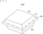
- FIG. 2 is a perspective view briefly showing a battery pack housing according to an embodiment of the present invention.
- the battery pack housing 1000 includes a lower case 200 configured to receive a plurality of battery cells and various components constituting a battery pack and an upper cover 100 coupled to the lower case 200 in order to form the battery pack housing 1000 together with the lower case.
- a battery cell used to manufacture a battery pack may be classified as a cylindrical battery cell, a prismatic battery cell, or a pouch-shaped battery cell depending on the shape of a case.
- the battery pack housing 1000 according to the present invention may be used to manufacture various battery packs without being limited to the shape of the battery cell.
- the battery pack housing 1000 further includes a fastening means 300 configured to couple the lower case 200 and the upper cover 100 to each other.
- bolts and nuts capable of mechanically coupling the lower case 200 and the upper cover 100 to each other may be used as the fastening means 300.
- the present invention is not limited thereto, and various known fastening means may be used.
- the battery pack housing 1000 according to the present invention may generally have various structures such that various components, such as an apparatus for connection with an external device or a cooling apparatus, are provided inside or outside a battery pack.
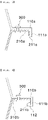
- FIG. 3 is a sectional view showing coupling between an upper cover fastening portion and a lower case fastening portion according to an embodiment of the present invention.
- an upper cover fastening portion 110a is formed at the edge of the upper cover 100 in a state of protruding and extending outwards
- a lower case fastening portion 210a is formed at the edge of the lower case 200 in a state of protruding and extending outwards so as to correspond to the upper cover fastening portion.
- the lower case fastening portion 210a is located at the upper cover fastening portion 110a, and then the lower case 200 and the upper cover 100 are coupled to each other using the fastening means 300.
- the bolts When bolts and nuts are used as the fastening means 300, the bolts are inserted through a plurality of through-holes formed in each of the upper cover fastening portion 110a and the lower case fastening portion 210a, and then the nuts are fastened to the bolts, whereby the lower case 200 and the upper cover 100 are coupled to each other.
- the battery pack housing 1000 is provided with a first bent portion 111a formed as the result of the end of the upper cover fastening portion 110a being bent downwards and an extension portion 211a formed as the result of the end of the lower case fastening portion 210a being bent downwards so as to correspond to the first bent portion 111a.
- FIG. 4 is a sectional view showing coupling between an upper cover fastening portion and a lower case fastening portion according to another embodiment of the present invention.
- the battery pack housing 1000 may further include a second bent portion formed at the end of a first bent portion 111b so as to be bent therefrom in a direction toward the center of the battery pack housing 1000.
- the upper cover fastening portion 110a or 110b and the lower case fastening portion 210a or 210b coupled to each other via the fastening means 300 are fastened to each other in contact with each other.
- first bent portion 111a or 111b and the extension portion 211a or 211b and the second bent portion 112 and the extension portion 211b may be configured to contact each other at the time of fastening.
- each of the first bent portion 111a or 111b, the second bent portion 112, and the extension portion 211a or 211b may be made of a material that is plastically deformed by heat generated when fire breaks out or a material that melts at a portion or the entirety of the contact surface thereof, such as thermoplastic.
- the gap between the first bent portion 111a or 111b and the extension portion 211a or 211b and the gap between the second bent portion 112 and the extension portion 211a or 211b is hermetically sealed by the molten material, whereby it is possible to prevent introduction of oxygen from the outside.
- the entireties of the upper cover fastening portion 110a or 110b and the lower case fastening portion 210a or 210b may be made of such a material, instead of only the first bent portion 111a or 111b, the second bent portion 112, and the extension portion 211a or 211b, which are ends of the upper cover fastening portion 110a or 110b and the lower case fastening portion 210a or 210b, being made of the material.
- the entirety of the upper cover 100 may be made of a material that is plastically deformed by heat generated when fire breaks out, such as thermoplastic, whereby it is possible to prevent introduction of oxygen from the outside as the result of deformation of the upper cover.
- the entirety of the upper cover 100 is made of the same material, as described above, it is possible to more easily manufacture the upper cover 100 using various known plastic processing methods.
- the degree of coupling between the upper cover 100 and the lower case 200 is increased, whereby mechanical stiffness against vibration and impact is increased.
- a plurality of battery cells may be received in the battery pack housing 1000 having the fire inhibition function according to the present invention, and various components configured to control operation of the battery cells may be added to manufacture a battery pack.
- the battery pack manufactured as described above is generally used as a power source for various devices, such as electronic devices and electric vehicles.
Landscapes
- Chemical & Material Sciences (AREA)
- Chemical Kinetics & Catalysis (AREA)
- Electrochemistry (AREA)
- General Chemical & Material Sciences (AREA)
- Engineering & Computer Science (AREA)
- Manufacturing & Machinery (AREA)
- Battery Mounting, Suspending (AREA)
Abstract
Description
- This application claims the benefit of priority to
Korean Patent Application No. 2020-0135104 filed on October 19, 2020 - The present invention relates to a battery pack housing including a bent portion formed at the end of an upper cover fastening portion and an extension portion formed at the end of a lower case fastening portion in order to prevent introduction of oxygen, thereby inhibiting spread of fire.
- With technological development of mobile devices, such as smartphones, laptop computers, and digital cameras, and an increase in demand therefor, research on secondary batteries, which are capable of being charged and discharged, has been actively conducted. In addition, secondary batteries, which are energy sources substituting for fossil fuels causing air pollution, have been applied to an electric vehicle (EV), a hybrid electric vehicle (HEV), a plug-in hybrid electric vehicle (P-HEV), and an energy storage system (ESS).
- There are a lithium ion battery, a lithium polymer battery, a nickel-cadmium battery, a nickel-hydride battery, and a nickel-zinc battery as secondary batteries that are widely used at present. The operating voltage of a unit secondary battery cell, i.e. a unit battery cell, is about 2.0V to 5.0V. In the case in which output voltage higher than the above operating voltage is required, therefore, a plurality of battery cells may be connected to each other in series to constitute a battery cell assembly. In addition, battery cell assemblies may be connected to each other in series or in parallel to constitute a battery module depending on required output voltage or charge and discharge capacities. In general, a battery pack is manufactured using at least one battery module by adding an additional component.
- Since a lithium secondary battery has a risk of explosion or fire due to heat generation, however, securing safety is an important problem. If such an abnormal phenomenon is not dealt with in the initial stage, the abnormal phenomenon propagates to an adjacent secondary battery, whereby a battery pack may be greatly damaged.
- Meanwhile, a battery pack is generally manufactured so as to have a structure in which a plurality of battery cells and various components are received in a battery pack housing.
-
FIG. 1 is a perspective view briefly showing a conventional battery pack housing 1. The conventional battery pack housing 1 includes alower case 20 configured to receive a plurality of battery cells, anupper cover 10 coupled to thelower case 20 in order to form the battery pack housing 1 together with the lower case, and a fastening means 30 configured to couple thelower case 20 and theupper case 10 to each other. - In addition, an upper
cover fastening portion 11 is formed at the edge of theupper cover 10 in a state of protruding and extending outwards, a lowercase fastening portion 21 is formed at thelower case 20 so as to have a shape corresponding to the upper cover fastening portion, and theupper cover 10 and thelower case 20 are coupled to each other via a fastening means 30, such as a bolt and nut. - Even though fastening is performed as described above, however, airtight hermetic sealing is not completely achieved at the joint at which the
upper cover 10 and thelower case 20 are coupled to each other. - When fire breaks out in the conventional battery pack housing 1, therefore, external oxygen is abruptly introduced through a microscopic gap in the joint of the
lower case 20 and theupper cover 10 due to an instantaneous difference in pressure between the inside and outside of the conventional battery pack housing, whereby fire may spread and explosion may occur in a severe case. - In order to solve such a sealing problem, a method of sealing the entirety of the joint using a sealing member may be used. In this case, however, an additional process is necessary and thus cost is increased. Furthermore, it is difficult to separate the
lower case 20 and theupper cover 10 from each other after sealing. - The present invention has been made in view of the above problems, and it is an object of the present invention to provide a battery pack housing including a bent portion formed at the end of an upper cover fastening portion and an extension portion formed at the end of a lower case fastening portion in order to prevent introduction of oxygen, thereby inhibiting spread of fire.
- In order to accomplish the above object, a battery pack housing according to the present invention includes a lower case configured to receive a plurality of battery cells and an upper cover located on the lower case so as to be coupled to the lower case in order to inhibit fire spread when fire breaks out in a battery pack, wherein the lower case includes a lower case fastening portion formed at the edge of the lower case so as to protrude and extend outwards, the upper cover includes an upper cover fastening portion formed at the edge of the upper cover so as to protrude and extend outwards, the upper cover fastening portion being coupled to the lower case fastening portion, and the upper cover fastening portion includes a first bent portion formed as the result of the end of the upper cover fastening portion being bent downwards.
- Also, the battery pack housing according to the present invention may further include a fastening means configured to couple the lower case and the upper cover to each other.
- Also, in the battery pack housing according to the present invention, the fastening means may be a bolt and nut.
- Also, in the battery pack housing according to the present invention, the fastening means may be inserted through a through-hole formed in the upper cover fastening portion and a through-hole formed in the lower case fastening portion to fasten the upper cover fastening portion and the lower case fastening portion to each other.
- Also, in the battery pack housing according to the present invention, the lower case fastening portion may include an extension portion formed as the result of the end of the lower case fastening portion being bent in the same direction as the first bent portion, the extension portion being located at a position corresponding to the first bent portion.
- Also, in the battery pack housing according to the present invention, the upper cover fastening portion may further include a second bent portion formed at the end of the first bent portion so as to be bent toward the center of the battery pack housing.
- Also, in the battery pack housing according to the present invention, each of the first bent portion and the extension portion may be made of thermoplastic.
- Also, in the battery pack housing according to the present invention, the second bent portion may be made of thermoplastic.
- In addition, a battery pack according to the present invention includes one of the battery pack housings according to the present invention.
- In addition, a device according to the present invention includes the battery pack according to the present invention.
- A battery pack housing according to the present invention has an advantage in that a bent portion is provided at the end of an upper cover fastening portion and an extension portion is provided at the end of a lower case fastening portion, whereby it is possible to prevent introduction of oxygen from the outside and to inhibit discharge of flames to the outside when fire breaks out in a battery pack.
- In addition, the battery pack housing according to the present invention has an advantage in that hermeticity between the inside and outside of the battery pack housing is improved even though a separate sealing process is not added.
- In addition, the battery pack housing according to the present invention has an advantage in that the degree of coupling between the upper cover and the lower case is increased due to the bent portion provided at the upper cover fastening portion and the extension portion provided at the lower case fastening portion, whereby mechanical stiffness against vibration and impact is increased.
-
-
FIG. 1 is a perspective view briefly showing a conventional battery pack housing. -
FIG. 2 is a perspective view briefly showing a battery pack housing according to an embodiment of the present invention. -
FIG. 3 is a sectional view showing coupling between an upper cover fastening portion and a lower case fastening portion according to an embodiment of the present invention. -
FIG. 4 is a sectional view showing coupling between an upper cover fastening portion and a lower case fastening portion according to another embodiment of the present invention. - In the present application, it should be understood that the terms "comprises," "has," "includes," etc. specify the presence of stated features, numbers, steps, operations, elements, components, or combinations thereof, but do not preclude the presence or addition of one or more other features, numbers, steps, operations, elements, components, or combinations thereof.
- In addition, the same reference numbers will be used throughout the drawings to refer to parts that perform similar functions or operations. In the case in which one part is said to be connected to another part in the specification, not only may the one part be directly connected to the other part, but also, the one part may be indirectly connected to the other part via a further part. In addition, that a certain element is included does not mean that other elements are excluded, but means that such elements may be further included unless mentioned otherwise.
- Hereinafter, a battery pack housing according to the present invention will be described with reference to the accompanying drawings.
-
FIG. 2 is a perspective view briefly showing a battery pack housing according to an embodiment of the present invention. - When describing the
battery pack housing 1000 according to the present invention with reference toFIG. 2 , thebattery pack housing 1000 includes alower case 200 configured to receive a plurality of battery cells and various components constituting a battery pack and anupper cover 100 coupled to thelower case 200 in order to form thebattery pack housing 1000 together with the lower case. - In general, a battery cell used to manufacture a battery pack may be classified as a cylindrical battery cell, a prismatic battery cell, or a pouch-shaped battery cell depending on the shape of a case. The battery pack housing 1000 according to the present invention may be used to manufacture various battery packs without being limited to the shape of the battery cell.
- In addition, the
battery pack housing 1000 further includes a fastening means 300 configured to couple thelower case 200 and theupper cover 100 to each other. - In the present invention, bolts and nuts capable of mechanically coupling the
lower case 200 and theupper cover 100 to each other may be used as the fastening means 300. However, the present invention is not limited thereto, and various known fastening means may be used. - Meanwhile, although parts unnecessary to describe features of the
battery pack housing 1000 according to the present invention are briefly shown, as shown inFIG. 2 , the battery pack housing 1000 according to the present invention may generally have various structures such that various components, such as an apparatus for connection with an external device or a cooling apparatus, are provided inside or outside a battery pack. -
FIG. 3 is a sectional view showing coupling between an upper cover fastening portion and a lower case fastening portion according to an embodiment of the present invention. - When describing the structure of the battery pack housing 1000 according to the present invention in more detail with reference to
FIGS. 2 and3 , an uppercover fastening portion 110a is formed at the edge of theupper cover 100 in a state of protruding and extending outwards, and a lowercase fastening portion 210a is formed at the edge of thelower case 200 in a state of protruding and extending outwards so as to correspond to the upper cover fastening portion. - Consequently, the lower
case fastening portion 210a is located at the uppercover fastening portion 110a, and then thelower case 200 and theupper cover 100 are coupled to each other using the fastening means 300. - When bolts and nuts are used as the fastening means 300, the bolts are inserted through a plurality of through-holes formed in each of the upper cover fastening
portion 110a and the lower case fasteningportion 210a, and then the nuts are fastened to the bolts, whereby thelower case 200 and theupper cover 100 are coupled to each other. - Even though fastening is performed using the fastening means 300, however, hermetic sealing is not completely achieved. As shown in
FIG. 3 , therefore, the battery pack housing 1000 according to the present invention is provided with afirst bent portion 111a formed as the result of the end of the uppercover fastening portion 110a being bent downwards and anextension portion 211a formed as the result of the end of the lowercase fastening portion 210a being bent downwards so as to correspond to thefirst bent portion 111a. - When fire breaks out in the
battery pack housing 1000, introduction of oxygen into the battery pack housing is difficult due to the provision of thefirst bent portion 111a and theextension portion 211a, compared to a conventional battery pack housing. - As a result, it is possible to inhibit fire spread due to introduction of oxygen from the outside, and flames in the battery pack housing are prevented from being directly discharged to the outside.
- In addition, when the first
bent portion 111a and theextension portion 211a are formed, an additional sealing process of hermetically sealing thebattery pack housing 1000 is not necessary, and theupper cover 100 and thelower case 200 may be easily separated from each other by simply removing the fastening means. -
FIG. 4 is a sectional view showing coupling between an upper cover fastening portion and a lower case fastening portion according to another embodiment of the present invention. - As shown in
FIG. 4 , thebattery pack housing 1000 according to the present invention may further include a second bent portion formed at the end of a firstbent portion 111b so as to be bent therefrom in a direction toward the center of thebattery pack housing 1000. - In the case in which the second
bent portion 112 is provided at the uppercover fastening portion 110b in addition to the firstbent portion 111b, as described above, it is more difficult to form an oxygen introduction path, whereby it is possible to more effectively prevent introduction of oxygen from the outside. - Meanwhile, as shown in
FIGS. 3 and 4 , the uppercover fastening portion case fastening portion - In addition, the first
bent portion extension portion bent portion 112 and theextension portion 211b may be configured to contact each other at the time of fastening. - Additionally, in the
battery pack housing 1000 according to the present invention, each of the firstbent portion bent portion 112, and theextension portion - In this case, the gap between the first
bent portion extension portion bent portion 112 and theextension portion - In addition, the entireties of the upper
cover fastening portion case fastening portion bent portion bent portion 112, and theextension portion cover fastening portion case fastening portion - Alternatively, the entirety of the
upper cover 100 may be made of a material that is plastically deformed by heat generated when fire breaks out, such as thermoplastic, whereby it is possible to prevent introduction of oxygen from the outside as the result of deformation of the upper cover. - In the case in which the entirety of the
upper cover 100 is made of the same material, as described above, it is possible to more easily manufacture theupper cover 100 using various known plastic processing methods. - Meanwhile, in the case in which a structure, such as the first
bent portion bent portion 112, or theextension portion battery pack housing 1000, as described above, the degree of coupling between theupper cover 100 and thelower case 200 is increased, whereby mechanical stiffness against vibration and impact is increased. - In addition, a plurality of battery cells may be received in the
battery pack housing 1000 having the fire inhibition function according to the present invention, and various components configured to control operation of the battery cells may be added to manufacture a battery pack. - The battery pack manufactured as described above is generally used as a power source for various devices, such as electronic devices and electric vehicles.
- Although the specific details of the present invention have been described in detail, those skilled in the art will appreciate that the detailed description thereof discloses only preferred embodiments of the present invention and thus does not limit the scope of the present invention. Accordingly, those skilled in the art will appreciate that various changes and modifications are possible, without departing from the category and technical idea of the present invention, and it will be obvious that such changes and modifications fall within the scope of the appended claims.
-
- 1000: Battery pack housing
- 100: Upper cover
- 110, 110a, 110b: Upper cover fastening portions
- 111a, 111b: First bent portions
- 112: Second bent portion
- 200: Lower case
- 210a, 210b: Lower case fastening portions
- 211a, 211b: Extension portions
- 300: Fastening means
Claims (10)
- A battery pack housing comprising:a lower case configured to receive a plurality of battery cells; andan upper cover located on the lower case so as to be coupled to the lower case,wherein the lower case comprises a lower case fastening portion formed at an edge of the lower case so as to protrude and extend outwards,wherein the upper cover comprises an upper cover fastening portion formed at an edge of the upper cover so as to protrude and extend outwards, the upper cover fastening portion being coupled to the lower case fastening portion, andwherein the upper cover fastening portion comprises a first bent portion formed as a result of an end of the upper cover fastening portion being bent downwards.
- The battery pack housing according to claim 1, further comprising a fastening means configured to couple the lower case and the upper cover to each other.
- The battery pack housing according to claim 2, wherein the fastening means is a bolt and nut.
- The battery pack housing according to claim 2, wherein the fastening means is inserted through a through-hole formed in the upper cover fastening portion and a through-hole formed in the lower case fastening portion to fasten the upper cover fastening portion and the lower case fastening portion to each other.
- The battery pack housing according to claim 2, wherein the lower case fastening portion comprises an extension portion formed as a result of an end of the lower case fastening portion being bent in an identical direction to the first bent portion, the extension portion being located at a position corresponding to the first bent portion.
- The battery pack housing according to claim 5, wherein the upper cover fastening portion further comprises a second bent portion formed at an end of the first bent portion so as to be bent toward a center of the battery pack housing.
- The battery pack housing according to claim 5, wherein each of the first bent portion and the extension portion is made of thermoplastic.
- The battery pack housing according to claim 6, wherein the second bent portion is made of thermoplastic.
- A battery pack comprising the battery pack housing according to any one of claims 1 to 8.
- A device comprising the battery pack according to claim 9.
Applications Claiming Priority (2)
| Application Number | Priority Date | Filing Date | Title |
|---|---|---|---|
| KR1020200135104A KR20220051561A (en) | 2020-10-19 | 2020-10-19 | Battery pack housing with fire suppression structure |
| PCT/KR2021/014085 WO2022086030A1 (en) | 2020-10-19 | 2021-10-13 | Battery pack housing having fire suppression structure |
Publications (3)
| Publication Number | Publication Date |
|---|---|
| EP4109647A1 true EP4109647A1 (en) | 2022-12-28 |
| EP4109647A4 EP4109647A4 (en) | 2024-07-24 |
| EP4109647B1 EP4109647B1 (en) | 2025-04-16 |
Family
ID=81290823
Family Applications (1)
| Application Number | Title | Priority Date | Filing Date |
|---|---|---|---|
| EP21883101.4A Active EP4109647B1 (en) | 2020-10-19 | 2021-10-13 | Battery pack housing having fire inhibition structure |
Country Status (8)
| Country | Link |
|---|---|
| US (1) | US12573704B2 (en) |
| EP (1) | EP4109647B1 (en) |
| JP (1) | JP7551089B2 (en) |
| KR (1) | KR20220051561A (en) |
| CN (1) | CN115699422A (en) |
| ES (1) | ES3026512T3 (en) |
| HU (1) | HUE071351T2 (en) |
| WO (1) | WO2022086030A1 (en) |
Families Citing this family (1)
| Publication number | Priority date | Publication date | Assignee | Title |
|---|---|---|---|---|
| WO2025197743A1 (en) * | 2024-03-19 | 2025-09-25 | 三菱自動車工業株式会社 | Fastening structure |
Family Cites Families (25)
| Publication number | Priority date | Publication date | Assignee | Title |
|---|---|---|---|---|
| JP5182540B2 (en) * | 2004-12-07 | 2013-04-17 | トヨタ自動車株式会社 | Case for fuel cell |
| JP5091060B2 (en) | 2007-11-21 | 2012-12-05 | 本田技研工業株式会社 | Vehicle power supply |
| CN103119746B (en) * | 2010-06-04 | 2016-01-06 | A123系统有限责任公司 | Curling prismatic battery structure |
| JP2012089415A (en) * | 2010-10-21 | 2012-05-10 | Sharp Corp | Secondary battery and battery pack |
| JP2013033688A (en) * | 2011-08-03 | 2013-02-14 | Sharp Corp | Secondary battery |
| JP5652377B2 (en) | 2011-11-17 | 2015-01-14 | 三菱自動車工業株式会社 | Electric car battery pack structure |
| KR101174664B1 (en) * | 2012-02-08 | 2012-08-17 | 주식회사 해라이트 | Box for containing battery and constructional structure of the same |
| KR101698770B1 (en) | 2012-03-23 | 2017-01-23 | 삼성에스디아이 주식회사 | Battery pack |
| KR101315741B1 (en) * | 2012-03-23 | 2013-10-10 | 현대자동차주식회사 | Battery Pack Case Assembly for Electric Vehicles Using Plastic Composite and method for manufacturing the same |
| JP2014022154A (en) * | 2012-07-17 | 2014-02-03 | Mitsubishi Motors Corp | Cover positioning structure for battery pack |
| KR20140110444A (en) * | 2013-03-08 | 2014-09-17 | 현대모비스 주식회사 | Combination structure of outside installation battery pack of vehicle and method thereof |
| JP6245518B2 (en) * | 2014-02-27 | 2017-12-13 | 三菱自動車工業株式会社 | Electric connector mounting structure for battery pack for electric vehicle |
| US20170018747A1 (en) * | 2014-03-31 | 2017-01-19 | Nec Corporation | Storage battery apparatus |
| KR20160116566A (en) | 2015-03-30 | 2016-10-10 | 주식회사 엘지화학 | Pack Case And Battery Pack Comprising The Same |
| CN105398666A (en) | 2015-10-22 | 2016-03-16 | 台山市世亨包装材料有限公司 | Sealed container |
| CN105514311B (en) * | 2015-11-30 | 2018-03-16 | 奇瑞汽车股份有限公司 | A kind of battery pack case and the battery bag with the battery pack case |
| KR102250195B1 (en) * | 2016-07-07 | 2021-05-07 | 주식회사 엘지화학 | Cap assembly for secondary battery and method for fabricating the same |
| CN206022437U (en) | 2016-08-31 | 2017-03-15 | 捷星新能源科技(苏州)有限公司 | A kind of battery bag box body sealing structure |
| CN206163565U (en) | 2016-11-01 | 2017-05-10 | 天津国安盟固利新能源有限公司 | Lithium battery box |
| CN206364071U (en) | 2016-12-30 | 2017-07-28 | 风度(常州)汽车研发院有限公司 | A kind of double sealing structure |
| CN207398211U (en) * | 2017-08-31 | 2018-05-22 | 惠州市蓝微新源技术有限公司 | A kind of Battery case with multiple waterproof structure |
| CN207409557U (en) * | 2017-10-31 | 2018-05-25 | 宁德时代新能源科技股份有限公司 | Babinet and battery pack |
| CN207438909U (en) * | 2017-11-22 | 2018-06-01 | 李成明 | A kind of riveted type expansion tank of wall-hung boiler |
| KR102222762B1 (en) | 2019-05-23 | 2021-03-04 | 주식회사 한테크 | Automatic separating apparatus of smartphone front panel and backcover |
| CN110277520A (en) | 2019-06-14 | 2019-09-24 | 湖南科霸汽车动力电池有限责任公司 | A battery pack case and battery pack |
-
2020
- 2020-10-19 KR KR1020200135104A patent/KR20220051561A/en active Pending
-
2021
- 2021-10-13 ES ES21883101T patent/ES3026512T3/en active Active
- 2021-10-13 JP JP2022575450A patent/JP7551089B2/en active Active
- 2021-10-13 US US17/915,828 patent/US12573704B2/en active Active
- 2021-10-13 WO PCT/KR2021/014085 patent/WO2022086030A1/en not_active Ceased
- 2021-10-13 EP EP21883101.4A patent/EP4109647B1/en active Active
- 2021-10-13 HU HUE21883101A patent/HUE071351T2/en unknown
- 2021-10-13 CN CN202180040693.5A patent/CN115699422A/en active Pending
Also Published As
| Publication number | Publication date |
|---|---|
| JP2023530400A (en) | 2023-07-18 |
| EP4109647A4 (en) | 2024-07-24 |
| WO2022086030A1 (en) | 2022-04-28 |
| US12573704B2 (en) | 2026-03-10 |
| CN115699422A (en) | 2023-02-03 |
| HUE071351T2 (en) | 2025-08-28 |
| US20230155236A1 (en) | 2023-05-18 |
| EP4109647B1 (en) | 2025-04-16 |
| KR20220051561A (en) | 2022-04-26 |
| JP7551089B2 (en) | 2024-09-17 |
| ES3026512T3 (en) | 2025-06-11 |
Similar Documents
| Publication | Publication Date | Title |
|---|---|---|
| EP3907818B1 (en) | Battery pack having movable busbar assembly and secondary battery including the same | |
| EP4443629B1 (en) | Battery module | |
| CN109891626B (en) | Battery pack | |
| CN204720485U (en) | Battery pack and vehicle | |
| KR101191658B1 (en) | Rechargeable battery | |
| CN103931019B (en) | Battery module with improved safety and battery pack including same | |
| EP3629396A1 (en) | Battery module having initial pressing force strengthening structure for cell assembly, and method for manufacturing same | |
| US20100297482A1 (en) | Battery module of improved safety and middle or large-sized battery pack containing the same | |
| EP2930771B1 (en) | Rechargeable battery | |
| EP3972039B1 (en) | Cell module assembly and method of manufacturing the same | |
| US20150137767A1 (en) | Protection apparatus for rechargeable battery | |
| CN109075304B (en) | Rechargeable battery with diaphragm | |
| EP4261992A1 (en) | Battery module case and battery module comprising the same | |
| CN110612617A (en) | Electrical assembly and battery pack including the same | |
| EP4276995B1 (en) | Multi-battery pack having compact structure | |
| EP4109647B1 (en) | Battery pack housing having fire inhibition structure | |
| US12438228B2 (en) | Battery cell, battery pack, and vehicle including same | |
| US20250357591A1 (en) | Battery pack | |
| EP4199225A1 (en) | Battery module, and battery pack and vehicle comprising same | |
| KR20200055336A (en) | Battery pack | |
| JP2019102222A (en) | Battery pack and housing body | |
| EP4443623A1 (en) | Rechargeable battery module | |
| EP4625655A1 (en) | Battery pack including battery module and vehicle including same | |
| EP4576410A1 (en) | Battery module, and battery pack and vehicle comprising same | |
| EP4507097A1 (en) | Gas exhausting device, battery cell, battery, and electric device |
Legal Events
| Date | Code | Title | Description |
|---|---|---|---|
| STAA | Information on the status of an ep patent application or granted ep patent |
Free format text: STATUS: THE INTERNATIONAL PUBLICATION HAS BEEN MADE |
|
| PUAI | Public reference made under article 153(3) epc to a published international application that has entered the european phase |
Free format text: ORIGINAL CODE: 0009012 |
|
| STAA | Information on the status of an ep patent application or granted ep patent |
Free format text: STATUS: REQUEST FOR EXAMINATION WAS MADE |
|
| 17P | Request for examination filed |
Effective date: 20220923 |
|
| AK | Designated contracting states |
Kind code of ref document: A1 Designated state(s): AL AT BE BG CH CY CZ DE DK EE ES FI FR GB GR HR HU IE IS IT LI LT LU LV MC MK MT NL NO PL PT RO RS SE SI SK SM TR |
|
| DAV | Request for validation of the european patent (deleted) | ||
| DAX | Request for extension of the european patent (deleted) | ||
| A4 | Supplementary search report drawn up and despatched |
Effective date: 20240625 |
|
| RIC1 | Information provided on ipc code assigned before grant |
Ipc: H01M 50/262 20210101ALI20240619BHEP Ipc: H01M 50/209 20210101ALI20240619BHEP Ipc: H01M 10/052 20100101ALI20240619BHEP Ipc: H01M 50/24 20210101ALI20240619BHEP Ipc: H01M 50/20 20210101AFI20240619BHEP |
|
| GRAP | Despatch of communication of intention to grant a patent |
Free format text: ORIGINAL CODE: EPIDOSNIGR1 |
|
| STAA | Information on the status of an ep patent application or granted ep patent |
Free format text: STATUS: GRANT OF PATENT IS INTENDED |
|
| RIC1 | Information provided on ipc code assigned before grant |
Ipc: H01M 50/262 20210101ALI20241125BHEP Ipc: H01M 50/209 20210101ALI20241125BHEP Ipc: H01M 10/052 20100101ALI20241125BHEP Ipc: H01M 50/24 20210101ALI20241125BHEP Ipc: H01M 50/20 20210101AFI20241125BHEP |
|
| INTG | Intention to grant announced |
Effective date: 20241212 |
|
| P01 | Opt-out of the competence of the unified patent court (upc) registered |
Free format text: CASE NUMBER: APP_583/2025 Effective date: 20250107 |
|
| GRAS | Grant fee paid |
Free format text: ORIGINAL CODE: EPIDOSNIGR3 |
|
| GRAA | (expected) grant |
Free format text: ORIGINAL CODE: 0009210 |
|
| STAA | Information on the status of an ep patent application or granted ep patent |
Free format text: STATUS: THE PATENT HAS BEEN GRANTED |
|
| AK | Designated contracting states |
Kind code of ref document: B1 Designated state(s): AL AT BE BG CH CY CZ DE DK EE ES FI FR GB GR HR HU IE IS IT LI LT LU LV MC MK MT NL NO PL PT RO RS SE SI SK SM TR |
|
| REG | Reference to a national code |
Ref country code: GB Ref legal event code: FG4D |
|
| REG | Reference to a national code |
Ref country code: CH Ref legal event code: EP |
|
| REG | Reference to a national code |
Ref country code: IE Ref legal event code: FG4D |
|
| REG | Reference to a national code |
Ref country code: DE Ref legal event code: R096 Ref document number: 602021029388 Country of ref document: DE |
|
| REG | Reference to a national code |
Ref country code: ES Ref legal event code: FG2A Ref document number: 3026512 Country of ref document: ES Kind code of ref document: T3 Effective date: 20250611 |
|
| REG | Reference to a national code |
Ref country code: NL Ref legal event code: MP Effective date: 20250416 |
|
| REG | Reference to a national code |
Ref country code: HU Ref legal event code: AG4A Ref document number: E071351 Country of ref document: HU |
|
| PG25 | Lapsed in a contracting state [announced via postgrant information from national office to epo] |
Ref country code: NL Free format text: LAPSE BECAUSE OF FAILURE TO SUBMIT A TRANSLATION OF THE DESCRIPTION OR TO PAY THE FEE WITHIN THE PRESCRIBED TIME-LIMIT Effective date: 20250416 |
|
| REG | Reference to a national code |
Ref country code: AT Ref legal event code: MK05 Ref document number: 1786437 Country of ref document: AT Kind code of ref document: T Effective date: 20250416 |
|
| PG25 | Lapsed in a contracting state [announced via postgrant information from national office to epo] |
Ref country code: PT Free format text: LAPSE BECAUSE OF FAILURE TO SUBMIT A TRANSLATION OF THE DESCRIPTION OR TO PAY THE FEE WITHIN THE PRESCRIBED TIME-LIMIT Effective date: 20250818 Ref country code: FI Free format text: LAPSE BECAUSE OF FAILURE TO SUBMIT A TRANSLATION OF THE DESCRIPTION OR TO PAY THE FEE WITHIN THE PRESCRIBED TIME-LIMIT Effective date: 20250416 |
|
| REG | Reference to a national code |
Ref country code: LT Ref legal event code: MG9D |
|
| PG25 | Lapsed in a contracting state [announced via postgrant information from national office to epo] |
Ref country code: GR Free format text: LAPSE BECAUSE OF FAILURE TO SUBMIT A TRANSLATION OF THE DESCRIPTION OR TO PAY THE FEE WITHIN THE PRESCRIBED TIME-LIMIT Effective date: 20250717 Ref country code: NO Free format text: LAPSE BECAUSE OF FAILURE TO SUBMIT A TRANSLATION OF THE DESCRIPTION OR TO PAY THE FEE WITHIN THE PRESCRIBED TIME-LIMIT Effective date: 20250716 |
|
| PG25 | Lapsed in a contracting state [announced via postgrant information from national office to epo] |
Ref country code: PL Free format text: LAPSE BECAUSE OF FAILURE TO SUBMIT A TRANSLATION OF THE DESCRIPTION OR TO PAY THE FEE WITHIN THE PRESCRIBED TIME-LIMIT Effective date: 20250416 |
|
| PG25 | Lapsed in a contracting state [announced via postgrant information from national office to epo] |
Ref country code: BG Free format text: LAPSE BECAUSE OF FAILURE TO SUBMIT A TRANSLATION OF THE DESCRIPTION OR TO PAY THE FEE WITHIN THE PRESCRIBED TIME-LIMIT Effective date: 20250416 |
|
| PGFP | Annual fee paid to national office [announced via postgrant information from national office to epo] |
Ref country code: BE Payment date: 20250922 Year of fee payment: 5 Ref country code: GB Payment date: 20250922 Year of fee payment: 5 |
|
| PG25 | Lapsed in a contracting state [announced via postgrant information from national office to epo] |
Ref country code: HR Free format text: LAPSE BECAUSE OF FAILURE TO SUBMIT A TRANSLATION OF THE DESCRIPTION OR TO PAY THE FEE WITHIN THE PRESCRIBED TIME-LIMIT Effective date: 20250416 |
|
| PG25 | Lapsed in a contracting state [announced via postgrant information from national office to epo] |
Ref country code: AT Free format text: LAPSE BECAUSE OF FAILURE TO SUBMIT A TRANSLATION OF THE DESCRIPTION OR TO PAY THE FEE WITHIN THE PRESCRIBED TIME-LIMIT Effective date: 20250416 |
|
| PGFP | Annual fee paid to national office [announced via postgrant information from national office to epo] |
Ref country code: FR Payment date: 20250925 Year of fee payment: 5 |
|
| PG25 | Lapsed in a contracting state [announced via postgrant information from national office to epo] |
Ref country code: RS Free format text: LAPSE BECAUSE OF FAILURE TO SUBMIT A TRANSLATION OF THE DESCRIPTION OR TO PAY THE FEE WITHIN THE PRESCRIBED TIME-LIMIT Effective date: 20250716 |
|
| PG25 | Lapsed in a contracting state [announced via postgrant information from national office to epo] |
Ref country code: IS Free format text: LAPSE BECAUSE OF FAILURE TO SUBMIT A TRANSLATION OF THE DESCRIPTION OR TO PAY THE FEE WITHIN THE PRESCRIBED TIME-LIMIT Effective date: 20250816 |
|
| PG25 | Lapsed in a contracting state [announced via postgrant information from national office to epo] |
Ref country code: LV Free format text: LAPSE BECAUSE OF FAILURE TO SUBMIT A TRANSLATION OF THE DESCRIPTION OR TO PAY THE FEE WITHIN THE PRESCRIBED TIME-LIMIT Effective date: 20250416 |
|
| PGFP | Annual fee paid to national office [announced via postgrant information from national office to epo] |
Ref country code: HU Payment date: 20251029 Year of fee payment: 5 |
|
| PGFP | Annual fee paid to national office [announced via postgrant information from national office to epo] |
Ref country code: DE Payment date: 20250922 Year of fee payment: 5 |
|
| PG25 | Lapsed in a contracting state [announced via postgrant information from national office to epo] |
Ref country code: SM Free format text: LAPSE BECAUSE OF FAILURE TO SUBMIT A TRANSLATION OF THE DESCRIPTION OR TO PAY THE FEE WITHIN THE PRESCRIBED TIME-LIMIT Effective date: 20250416 Ref country code: DK Free format text: LAPSE BECAUSE OF FAILURE TO SUBMIT A TRANSLATION OF THE DESCRIPTION OR TO PAY THE FEE WITHIN THE PRESCRIBED TIME-LIMIT Effective date: 20250416 |
|
| REG | Reference to a national code |
Ref country code: DE Ref legal event code: R097 Ref document number: 602021029388 Country of ref document: DE |
|
| PG25 | Lapsed in a contracting state [announced via postgrant information from national office to epo] |
Ref country code: CZ Free format text: LAPSE BECAUSE OF FAILURE TO SUBMIT A TRANSLATION OF THE DESCRIPTION OR TO PAY THE FEE WITHIN THE PRESCRIBED TIME-LIMIT Effective date: 20250416 |
|
| PG25 | Lapsed in a contracting state [announced via postgrant information from national office to epo] |
Ref country code: EE Free format text: LAPSE BECAUSE OF FAILURE TO SUBMIT A TRANSLATION OF THE DESCRIPTION OR TO PAY THE FEE WITHIN THE PRESCRIBED TIME-LIMIT Effective date: 20250416 |
|
| PG25 | Lapsed in a contracting state [announced via postgrant information from national office to epo] |
Ref country code: SK Free format text: LAPSE BECAUSE OF FAILURE TO SUBMIT A TRANSLATION OF THE DESCRIPTION OR TO PAY THE FEE WITHIN THE PRESCRIBED TIME-LIMIT Effective date: 20250416 |
|
| PG25 | Lapsed in a contracting state [announced via postgrant information from national office to epo] |
Ref country code: IT Free format text: LAPSE BECAUSE OF FAILURE TO SUBMIT A TRANSLATION OF THE DESCRIPTION OR TO PAY THE FEE WITHIN THE PRESCRIBED TIME-LIMIT Effective date: 20250416 |
|
| PGFP | Annual fee paid to national office [announced via postgrant information from national office to epo] |
Ref country code: ES Payment date: 20251117 Year of fee payment: 5 |
|
| PG25 | Lapsed in a contracting state [announced via postgrant information from national office to epo] |
Ref country code: RO Free format text: LAPSE BECAUSE OF FAILURE TO SUBMIT A TRANSLATION OF THE DESCRIPTION OR TO PAY THE FEE WITHIN THE PRESCRIBED TIME-LIMIT Effective date: 20250416 |
|
| PLBE | No opposition filed within time limit |
Free format text: ORIGINAL CODE: 0009261 |
|
| STAA | Information on the status of an ep patent application or granted ep patent |
Free format text: STATUS: NO OPPOSITION FILED WITHIN TIME LIMIT |
|
| REG | Reference to a national code |
Ref country code: CH Ref legal event code: L10 Free format text: ST27 STATUS EVENT CODE: U-0-0-L10-L00 (AS PROVIDED BY THE NATIONAL OFFICE) Effective date: 20260225 |
|
| 26N | No opposition filed |
Effective date: 20260119 |