EP4109579A1 - Electrode sheet connection method and electrode sheet - Google Patents
Electrode sheet connection method and electrode sheet Download PDFInfo
- Publication number
- EP4109579A1 EP4109579A1 EP21889378.2A EP21889378A EP4109579A1 EP 4109579 A1 EP4109579 A1 EP 4109579A1 EP 21889378 A EP21889378 A EP 21889378A EP 4109579 A1 EP4109579 A1 EP 4109579A1
- Authority
- EP
- European Patent Office
- Prior art keywords
- sheet
- electrode
- electrode sheet
- flexible connection
- connection sheet
- Prior art date
- Legal status (The legal status is an assumption and is not a legal conclusion. Google has not performed a legal analysis and makes no representation as to the accuracy of the status listed.)
- Granted
Links
Images


Classifications
-
- H—ELECTRICITY
- H01—ELECTRIC ELEMENTS
- H01M—PROCESSES OR MEANS, e.g. BATTERIES, FOR THE DIRECT CONVERSION OF CHEMICAL ENERGY INTO ELECTRICAL ENERGY
- H01M4/00—Electrodes
- H01M4/02—Electrodes composed of, or comprising, active material
- H01M4/04—Processes of manufacture in general
- H01M4/043—Processes of manufacture in general involving compressing or compaction
- H01M4/0435—Rolling or calendering
-
- H—ELECTRICITY
- H01—ELECTRIC ELEMENTS
- H01M—PROCESSES OR MEANS, e.g. BATTERIES, FOR THE DIRECT CONVERSION OF CHEMICAL ENERGY INTO ELECTRICAL ENERGY
- H01M4/00—Electrodes
- H01M4/02—Electrodes composed of, or comprising, active material
- H01M4/04—Processes of manufacture in general
-
- B—PERFORMING OPERATIONS; TRANSPORTING
- B65—CONVEYING; PACKING; STORING; HANDLING THIN OR FILAMENTARY MATERIAL
- B65H—HANDLING THIN OR FILAMENTARY MATERIAL, e.g. SHEETS, WEBS, CABLES
- B65H19/00—Changing the web roll
- B65H19/10—Changing the web roll in unwinding mechanisms or in connection with unwinding operations
- B65H19/18—Attaching, e.g. pasting, the replacement web to the expiring web
- B65H19/1842—Attaching, e.g. pasting, the replacement web to the expiring web standing splicing, i.e. the expiring web being stationary during splicing contact
- B65H19/1852—Attaching, e.g. pasting, the replacement web to the expiring web standing splicing, i.e. the expiring web being stationary during splicing contact taking place at a distance from the replacement roll
-
- B—PERFORMING OPERATIONS; TRANSPORTING
- B65—CONVEYING; PACKING; STORING; HANDLING THIN OR FILAMENTARY MATERIAL
- B65H—HANDLING THIN OR FILAMENTARY MATERIAL, e.g. SHEETS, WEBS, CABLES
- B65H19/00—Changing the web roll
- B65H19/10—Changing the web roll in unwinding mechanisms or in connection with unwinding operations
- B65H19/102—Preparing the leading end of the replacement web before splicing operation; Adhesive arrangements on leading end of replacement web; Tabs and adhesive tapes for splicing
-
- H—ELECTRICITY
- H01—ELECTRIC ELEMENTS
- H01M—PROCESSES OR MEANS, e.g. BATTERIES, FOR THE DIRECT CONVERSION OF CHEMICAL ENERGY INTO ELECTRICAL ENERGY
- H01M10/00—Secondary cells; Manufacture thereof
- H01M10/04—Construction or manufacture in general
- H01M10/0404—Machines for assembling batteries
-
- H—ELECTRICITY
- H01—ELECTRIC ELEMENTS
- H01M—PROCESSES OR MEANS, e.g. BATTERIES, FOR THE DIRECT CONVERSION OF CHEMICAL ENERGY INTO ELECTRICAL ENERGY
- H01M4/00—Electrodes
- H01M4/02—Electrodes composed of, or comprising, active material
- H01M4/13—Electrodes for accumulators with non-aqueous electrolyte, e.g. for lithium-accumulators; Processes of manufacture thereof
- H01M4/139—Processes of manufacture
-
- H—ELECTRICITY
- H01—ELECTRIC ELEMENTS
- H01M—PROCESSES OR MEANS, e.g. BATTERIES, FOR THE DIRECT CONVERSION OF CHEMICAL ENERGY INTO ELECTRICAL ENERGY
- H01M50/00—Constructional details or processes of manufacture of the non-active parts of electrochemical cells other than fuel cells, e.g. hybrid cells
- H01M50/40—Separators; Membranes; Diaphragms; Spacing elements inside cells
- H01M50/471—Spacing elements inside cells other than separators, membranes or diaphragms; Manufacturing processes thereof
- H01M50/48—Spacing elements inside cells other than separators, membranes or diaphragms; Manufacturing processes thereof characterised by the material
- H01M50/486—Organic material
-
- B—PERFORMING OPERATIONS; TRANSPORTING
- B65—CONVEYING; PACKING; STORING; HANDLING THIN OR FILAMENTARY MATERIAL
- B65H—HANDLING THIN OR FILAMENTARY MATERIAL, e.g. SHEETS, WEBS, CABLES
- B65H2301/00—Handling processes for sheets or webs
- B65H2301/40—Type of handling process
- B65H2301/46—Splicing
- B65H2301/462—Form of splice
- B65H2301/4622—Abutting article or web portions, i.e. edge to edge
- B65H2301/46222—Abutting article or web portions, i.e. edge to edge involving double butt splice, i.e. adhesive tape applied on both sides of the article or web portions
-
- B—PERFORMING OPERATIONS; TRANSPORTING
- B65—CONVEYING; PACKING; STORING; HANDLING THIN OR FILAMENTARY MATERIAL
- B65H—HANDLING THIN OR FILAMENTARY MATERIAL, e.g. SHEETS, WEBS, CABLES
- B65H2301/00—Handling processes for sheets or webs
- B65H2301/40—Type of handling process
- B65H2301/46—Splicing
- B65H2301/463—Splicing splicing means, i.e. means by which a web end is bound to another web end
- B65H2301/4631—Adhesive tape
- B65H2301/46314—Pieces of adhesive tape, e.g. labels
-
- B—PERFORMING OPERATIONS; TRANSPORTING
- B65—CONVEYING; PACKING; STORING; HANDLING THIN OR FILAMENTARY MATERIAL
- B65H—HANDLING THIN OR FILAMENTARY MATERIAL, e.g. SHEETS, WEBS, CABLES
- B65H2701/00—Handled material; Storage means
- B65H2701/10—Handled articles or webs
- B65H2701/19—Specific article or web
-
- B—PERFORMING OPERATIONS; TRANSPORTING
- B65—CONVEYING; PACKING; STORING; HANDLING THIN OR FILAMENTARY MATERIAL
- B65H—HANDLING THIN OR FILAMENTARY MATERIAL, e.g. SHEETS, WEBS, CABLES
- B65H2801/00—Application field
- B65H2801/72—Fuel cell manufacture
-
- Y—GENERAL TAGGING OF NEW TECHNOLOGICAL DEVELOPMENTS; GENERAL TAGGING OF CROSS-SECTIONAL TECHNOLOGIES SPANNING OVER SEVERAL SECTIONS OF THE IPC; TECHNICAL SUBJECTS COVERED BY FORMER USPC CROSS-REFERENCE ART COLLECTIONS [XRACs] AND DIGESTS
- Y02—TECHNOLOGIES OR APPLICATIONS FOR MITIGATION OR ADAPTATION AGAINST CLIMATE CHANGE
- Y02E—REDUCTION OF GREENHOUSE GAS [GHG] EMISSIONS, RELATED TO ENERGY GENERATION, TRANSMISSION OR DISTRIBUTION
- Y02E60/00—Enabling technologies; Technologies with a potential or indirect contribution to GHG emissions mitigation
- Y02E60/10—Energy storage using batteries
Definitions
- the present invention relates to a method for connecting electrode sheets, and more particularly, to a method for connecting electrode sheets for a secondary battery in a roll-to-roll process.
- the present invention also relates to an electrode sheet manufactured by the method of connecting electrode sheets.
- lithium secondary batteries are widely used as an energy source for various electronic products as well as various mobile devices because of their high energy density and high operating voltage and excellent storage and lifetime characteristics.
- the lithium secondary battery has a structure in which an electrode assembly for charging and discharging electric energy is built in a case is built. Electrodes (positive electrode and negative electrode) constituting the electrode assembly generate electric current through ion exchange, and each of the positive electrode and the negative electrode is manufactured as an electrode substrate (electrode sheet), which is obtained by applying an electrode slurry on the surface of a current collector made of an aluminum or copper film and drying the electrode slurry, is tab-processed (notching process) and is cut in an appropriate size.
- an electrode sheet, on which an electrode slurry has been applied includes a portion (a coated portion), on which an electrode slurry has been coated, and a portion (a non-coated portion), on which an electrode slurry has not been coated.
- Such processes of manufacturing and processing an electrode sheet are performed by a roll-to-roll process in which the electrode sheet, which is hung on a plurality of rollers, is moved on a predetermined path.
- the electrode sheet has been wound on the supply roller and is sequentially unwound to go through a series of manufacturing processes. If the electrode sheet of the supply roller is completely unwound, the electrode sheet needs to be replaced by a new electrode sheet by replacing the supply roller with a new supply roller.
- An auto splicer is an automatic connection device for continuously operating the machine when the use of one supply roller has been completed.
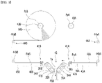
- FIG. 1 is a diagram showing an example of a conventional auto splicer for connecting electrode sheets between supply rollers in a roll-to-roll process.
- the auto splicer is a device for bonding a first web FwA, which was unwound from one roll and was almost used up, to a second web FwB which was unwound from another roll FrB.
- a second web FwB is unwound from a roll FrB and is moved to a splicing table of a splicing unit via guide rollers 44aB and 44bB. Webs moved from the splicing table 45B are bonded in a compression roller 42.
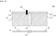
- FIG. 2 is a schematic diagram showing a process of connecting two electrode sheets in a roll-to-roll process.
- (a) of FIG. 2 is a plan view
- (b) of FIG. 2 is a side view.
- a tape 30 is attached on one end of each electrode sheet in order to connect a first electrode sheet 10 (for example, an electrode sheet before replacement) to a second electrode sheet 20 (for example, an electrode sheet after replacement).
- a connection tag 40 for identifying the termination of use of the first electrode sheet 10 is attached on the end of the first electrode sheet 10.
- coated portions 11 and 21, on which an electrode slurry has been coated are positioned at the lower portion of the first and second electrode sheets 10 and 20, and non-coated portions 12 and 22, on which an electrode slurry has not been coated, are positioned at the upper portion of the first and second electrode sheets 10 and 20.
- the other surface of the first and second electrode sheets 10 and 20 also has the same structure. Namely, the electrode sheet has a structure in which an electrode slurry has been applied on the surface and the other surface of a metal foil.
- connection part tape attachment part
- the connection part of electrode sheets may be disconnected due to stress. Namely, in a roll-to-roll process, the electrode sheet may be bent, and tension applied to the electrode sheet may not be constant. The tension may be different, depending to the portion of the electrode sheet. Hence, there may be a portion where tension is concentrated on the running path of the electrode sheet. When such a portion becomes the connection part of the electrode sheet, the electrode sheet may be broken at the connection part. If the connection part is broken, a defect rate increases, and the device operation rate drops.
- the tension applied to the electrode sheet is not constant in the roll-to-roll process, there comes to be a portion where meandering movement occurs.
- the moving path of the meandering movement portion is adjusted to obtain an accurate position before performing a process in a certain processing unit.
- an aspect of the present invention provides an electrode sheet connection method capable of relieving stress during the movement of the electrode sheet.
- another aspect of the present invention provides an electrode sheet for relieving stress during the movement of an electrode sheet and securing a margin at the time of adjustment of the meandering movement.
- a method for connecting electrode sheets in a roll-to-roll process of the present invention for solving the above problems includes: arranging a flexible connection sheet of a predetermined length between a first electrode sheet and a second electrode sheet; connecting the first electrode sheet to the flexible connection sheet by attaching one side of the first electrode sheet to one side of the flexible connection sheet using a first tape; and connecting the second electrode sheet to the flexible connection sheet by attaching one side of the second electrode sheet to the other side of the flexible connection sheet using a second tape.
- the flexible connection sheet is made of one selected from the group consisting of polyethylene terephthalate (PET), polyethylene naphthalate (PEN), oriented polypropylene (OPP), polyimide (PI), polybutylene terephthalate (PBT), polyester, polyacetal, polyamide, polyethersulfone, polyphenyleneoxide, polyphenylene sulfide, polyethylenenaphthalene, and flexible silicon.
- PET polyethylene terephthalate
- PEN polyethylene naphthalate
- OPP oriented polypropylene
- PI polyimide
- PBT polybutylene terephthalate
- polyester polyacetal
- polyamide polyethersulfone
- polyphenyleneoxide polyphenylene sulfide
- polyethylenenaphthalene polyethylenenaphthalene
- flexible silicon flexible silicon
- a length of the flexible connection sheet is in a range of 100 to 2000 mm.
- the first tape is attached on only electrode slurry coated portion of the first electrode sheet without being attached on electrode slurry non-coated portion of the first electrode sheet
- the second tape is attached on only electrode slurry coated portion of the second electrode sheet without being attached on electrode slurry non-coated portion of the second electrode sheet.
- a thickness of the flexible connection sheet may be the same as or smaller than thicknesses of the first electrode sheet and the second electrode sheet.
- the first electrode sheet or the second electrode sheet may not include a connection tag.
- a width of the flexible connection sheet may be the same as or smaller than widths of the first electrode sheet and the second electrode sheet.
- the width of the flexible connection sheet may be the same as widths of electrode slurry coated portions of the first electrode sheet and the second electrode sheet, and wherein the flexible connection sheet may be connected to the first electrode sheet and the second electrode sheet by arranging the flexible connection sheet to be parallel to the electrode slurry coated portions of the first electrode sheet and the second electrode sheet so that the width of the flexible connection sheet and the widths of the electrode slurry coated portions of the first electrode sheet and the second electrode sheet are opposite to each other.
- An electrode sheet provided by the present invention includes: a first electrode sheet; a second electrode sheet; a flexible connection sheet of a predetermined length, which is arranged between the first electrode sheet and the second electrode sheet; a first tape which is used to attach one side of the first electrode sheet to one side of the flexible connection sheet; and a second tape which is used to attach one side of the second electrode sheet to the other side of the flexible connection sheet.
- connection part of the electrode sheet it is possible to significantly reduce the possibility of fracture at the connection part of the electrode sheet by including a flexible connection sheet capable of relieving stress due to tension between electrode sheets.
- the flexible connection sheet provides a moving margin between electrode sheets before and after replacement, and a margin for adjusting the meandering movement may be secured by the moving margin.
- An object of the present invention is to relieve stress during a roll-to-roll process by arranging a flexible connection sheet at the time of connection of electrode sheets.
- a flexible connection sheet As shown in FIG. 2 , when an electrode sheet is attached to an electrode sheet without a margin and connection is made by a tape, stress applied during the roll-to-roll process could not be absorbed. Namely, an electrode foil (metal sheet) such as aluminum or copper of the electrode sheet is hard and is not stretched. As such, when a local tension is applied, a strong impact is given. Hence, when various processes are performed, the load by devices of various processes are given, and the tension of the electrode sheet is concentrated on the electrode sheet connection part, which causes a damage to the connection part.
- the tape is attached on only the coated portion for the attachment of the electrode sheet as in FIG. 2 , but the tension concentration of the roll-to-roll process could not be solved. Further, even if the tape itself is flexible, the tape is attached on the coated portion by the adhesive of the lower portion. As such, the tape failed to absorb stress.
- the present invention solves the existing technical problems by arranging a flexible connection sheet capable of relieving stress by absorbing tension between electrode sheets.
- FIG. 3 is a schematic diagram showing a process of connecting electrode sheets according to first embodiment of the present invention. (a) of FIG. 3 is a plan view, and (b) of FIG. 3 is a side view.
- a horizontal direction on the plan view of (a) of FIG. 3 is defined as the longitudinal direction of the electrode sheet, the flexible connection sheet and the tape, and the vertical direction is defined as the width direction.
- first electrode sheet 210 may be an electrode sheet before replacement, which has been completely used
- second electrode sheet 220 may be an electrode sheet after replacement which is to be newly used.
- the first electrode sheet 210 is unwound from a supply roller (running roller) (not shown), and the second electrode sheet 220 is unwound from another supply roller (standby roller) (not shown), to thereby be positioned at predetermined positions.
- a flexible connection sheet 250 of a predetermined length is arranged between the first and second electrodes 210 and 220.
- the first electrode sheet 210 is connected to the flexible connection sheet 250 by attaching one side of the first electrode sheet 210 to one side of the flexible connection sheet 250 by using a first tape 230a.
- the second electrode sheet 220 is connected to the flexible connection sheet 250 by attaching one side of the second electrode sheet 220 to the other side of the flexible connection sheet 250 using a second tape 230b, and as a result, the first and second electrode sheets 210 and 220 are connected to each other by tapes 230a and 230b while having the flexible connection sheet 250 between the first and second electrode sheets 210 and 220.
- the arrangement of the first and second electrode sheets 210 and 220 and the flexible connection sheet 250 and the attachment of the tape may be manually performed by a person, or may be performed in an automatic connection scheme using the above-described auto splicer.
- portions (coated portions) 211 and 221, on which an electrode slurry has been coated are positioned at the lower portion in the width direction of the first and second electrode sheets 210 and 220, and portions (non-coated portions) 212 and 222, on which an electrode slurry has not been coated, are positioned at the upper portion in the width direction of the first and second electrode sheets 210 and 220.
- the other surface of the first and second electrode sheets 210 and 220 also has the same structure. Namely, the electrode sheet has a structure in which an electrode slurry has been applied on the surface and the other surface of a metal foil.
- the non-coated portions 212 and 222 are formed only at the upper portion in the width direction of each electrode sheet, but it is possible that the non-coated portion is formed at each of the upper and lower portions in the width direction of the coated portions 211 and 221. This is a case that the coated portion is positioned between non-coated portions at the upper and lower portions in the width direction.
- the sheet part of the metal foil is omitted in the drawing, and only the overall appearance of the coated portions and electrode sheets 210 and 220 is shown. Further, since the connection tag 240 is removed later, it is not illustrated in the side view of (b) of FIG. 3 .
- a soft connection sheet which is more flexible than the electrode sheet made of a metal foil, may be used as the flexible connection sheet 250. Any flexible material capable of relieving local tension concentration of the roll-to-roll process may be used.
- the flexible connection sheet is made of one selected from the group consisting of polyethylene terephthalate (PET), polyethylene naphthalate (PEN), oriented polypropylene (OPP), polyimide (PI), polybutylene terephthalate (PBT), polyester, polyacetal, polyamide, polyethersulfone, polyphenyleneoxide, polyphenylene sulfide, polyethylenenaphthalene, and flexible silicon.
- the length and thickness of the flexible connection sheet 250 may be appropriately selected in the range of relieving stress between electrode sheets.
- electrode sheets There are various sizes of electrode sheets, depending on the type of manufactured electrode cells or batteries.
- the length of the flexible connection sheet 250 may be determined in a wide range according thereto.
- the length of the flexible connection sheet 250 may be in the range of 100 to 2000 mm.
- a 100 mm flexible connection sheet may be used for a ultrasmall battery, and a 2000 mm flexible connection sheet may be used for a large size battery such as a battery for a vehicle.
- the thickness of the flexible connection sheet 250 may be determined in consideration of the material and physical properties of the flexible connection sheet, and the characteristics of the battery. Herein, it is not preferable that the thickness of the flexible connection sheet 250 is greater than that of the first and second electrode sheets 210 and 220 in terms of relieving stress. Further, in the roll-to-roll process, the flexible connection sheet 250 is also wound on the roller together with the first and second electrode sheets 210 and 220. Hence, when making the flexible connection sheet thicker, stress may be concentrated on the flexible connection sheet 250 and its neighboring region. Hence, it is preferable that the thickness of the flexible connection sheet 250 is the same as the thickness of the first and second electrode sheets 210 and 220.
- the thickness of the flexible connection sheet 250 is smaller than that of the first and second electrode sheets 210 and 220 as shown in FIG. 3 so that the stress between electrode sheets can be better absorbed.
- the thickness of the flexible connection sheet 250 may be in the range of 10 to 30 ⁇ m, but the range may be changed according to the type or shape of the battery.
- a known general tape may be used as the adhesive tape for connecting the electrode sheets 210 and 220 to the flexible connection sheet 250. What is obtained by applying an acrylic adhesive on a film sheet made of paper, synthetic resin, etc. may be used as the tape.
- the flexible connection sheet 250 between the first electrode sheet 210 and the second electrode sheet 220 has been extended to a predetermined length to relieve stress as shown in FIG. 3 .
- two electrode sheets directly contact each other or there is a very small gap, and the tape is attached on one surface and the other surface. Hence, it was difficult to relieve or absorb stress.
- the present embodiment is different in that a flexible connection sheet 250 of a predetermined length has been extended between first and second electrode sheets 210 and 220.
- the first tapes 230a are attached on the first electrode sheet 210 and one side of the flexible connection sheet 250 and the second tapes 230b are attached on the second electrode sheet 220 and the other side of the flexible connection sheet 250 to thereby connect the flexible connection sheet 250 to the first and second electrode sheets 210 and 220 (see (b) of FIG. 3 ).
- the tape is attached on only the coated portions 211 and 221.
- the non-coated portions 212 and 222 are electrode foil (metal part), and various machining for battery production such as tab processing or laser processing are performed on the non-coated portions. Therefore, since the tape on the non-coated portion may interfere with machining, the tape is not attached on the non-coated portions 212 and 222. Further, when the adhesive of the tape flows into the electrode foil portion, it may influence the machining. Hence, it is preferable that the tapes 230a and 230b are attached on the coated portions 211 and 221 and the flexible connection sheet 250 with a slight interval with the non-coated portions 212 and 222.
- the tapes 230a and 230b are attached while covering a certain range of the portion around the end of each electrode sheet and a certain range of the portion around the side of the flexible connection sheet 250.
- the length of the tapes 230a and 230b, which cover the electrode sheet and the flexible connection sheet may be 30 mm in the case of an ultrasmall battery.
- the length of the tapes 230a and 230b may be determined in a range that may stably attach the electrode sheets 210 and 220 to the flexible connection sheet 250.
- the flexible connection sheet 250 is extended to a predetermined length to relieve stress, and the length of the tapes 230a and 230b is smaller than that of the flexible connection sheet 250.
- the length of the tapes 230a and 230b is determined in an appropriate range for connection between sheets, and the flexible connection sheet 250 is installed to relieve or absorb stress.
- each length may be determined in consideration of the purpose, and there is no particular relationship between the length of the tapes 230a and 230b and the length of the flexible connection sheet 250.
- the length of the flexible connection sheet may correspond to 3 to 10 times of the length of the tapes 230a and 230b.
- the adhesive force increases as an additional effect. Namely, when electrode sheets and the flexible connection sheet 250 are attached using tapes 230a and 230b, the adhesive force is higher, compared to when first and second electrode sheets 210 and 220 are directly bonded by tapes. Hence, since the adhesive force of the attached portion between the flexible connection sheet 250 and the tapes 230a and 230b is greater than that of the attached portion between the electrode sheet and the tape, the overall adhesive force increases.
- FIG. 4 is a schematic diagram illustrating a process of connecting electrode sheets according to a second embodiment of the present invention.
- connection tag 240 of FIG. 3 is removed.
- a connection tag 240 indicates that the use of the first electrode sheet 210 has been terminated, and the portion, on which the connection tag 240 is attached, is a connection part between two electrode sheets.
- the connection tag 240 may be identified with the naked eye, and the color can be identified by a color sensor.
- a conventional color sensor sometimes failed to recognize the connection tag 240 due to a low sensitivity. If the connection tag 240 is attached even during the battery assembly process after the connection of the electrode sheet, it may become a cause of a product defect.
- connection tag 240 is removed, and connection parts of first and second electrode sheets are configured by only the flexible connection sheet 250 and tapes 230a and 230b. Since the flexible connection sheet 250 is extended to a predetermined length, it is easily recognized with the naked eye. Further, since the flexible connection sheet 250, particularly a sheet made of a synthetic resin such as PET has an excellent light transmittance, the detection efficiency is excellent when sensed by an optical sensor (light transmittance type optical sensor).
- the flexible connection sheet 250 is sensed by a sensor, etc. without a connection tag 240. In this case, it is possible to easily recognize the point of time of termination of use of the electrode sheet, and the electrode connection part.
- FIG. 5 is a schematic diagram illustrating a process of connecting electrode sheets according to a third embodiment of the present invention.
- the present embodiment is different from the first embodiment in that the width of the flexible connection sheet 250 is smaller than the width of the first and second electrode sheets 210 and 220. Namely, in the first embodiment of FIG. 3 , the flexible connection sheet 250 is extended to the metal foil part corresponding to the non-coated portions 212 and 222. In this case, the width of the flexible connection sheet 250 is the same as that of the electrode sheet. In FIG. 5 , the width of the flexible connection sheet 250 is the same as the width of the coated portions 211 and 221.
- An electrode sheet is composed of a non-coated portion formed of only a metal foil, and a coated portion, on which an electrode slurry has been coated. As such, tension is not significantly applied to the non-coated portion, compared to the coated portion.
- the flexible connection sheet 250 may be made to connect only the coated portions 211 and 221 as in FIG. 5 . Further, in the structure of FIG. 3 , the adhesive leaked from the tapes 230a and 230b may flow into the non-coated portions 212 and 222 through the flexible connection sheet 250. Hence, it is preferable that the width of the flexible connection sheet 250 is limited to that of the coated portions 211 and 221. Further, in FIG.
- the flexible connection sheet 250 is not attached on the non-coated portions 212 and 222. They just contact each other. Hence, when the electrode sheet is wound, the end of the flexible connection sheet 250 contacting the non-coated portions 212 and 222 may be bent, and if such a bent portion is wound, stress imbalance may be caused.
- the width of the flexible connection sheet 250 is smaller than the width of the first and second electrode sheets 210 and 220, and particularly, the width of the flexible connection sheet 250 is the same as the width of the coated portions 211 and 221.
- the present invention has been described with reference to various embodiments.
- the present invention also relates to an electrode sheet manufactured by the method of connecting electrode sheets.
- An electrode sheet 200 of the present invention includes: a first electrode sheet 210; a second electrode sheet 220; a flexible connection sheet 250 of a predetermined length, which is arranged between the first electrode sheet 210 and the second electrode sheet 220; a first tape 230a which is used to attach one side of the first electrode sheet 210 to one side of the flexible connection sheet 250; and a second tape 230b which is used to attach one side of the second electrode sheet 220 to the other side of the flexible connection sheet 250. Since the electrode sheet 200 of the present invention includes a flexible connection sheet 250 extended to a predetermined length between first and second electrode sheets 210 and 220, the flexible connection sheet 250 relieves the local tension concentration, thereby relieving stress applied to the electrode sheet 200.
- the electrode sheet connection part may be easily recognized by the flexible connection sheet 250 without a connection tag.
- the width of the flexible connection sheet 250 may be the same as or smaller than the width of the first electrode sheet 210 and the second electrode sheet 220.
- the width of the flexible connection sheet 250 is smaller than the width of the first and second electrode sheets 210 and 220, it is preferable that the width of the flexible connection sheet 250 is the same as the width of the coated portions 211 and 221.
- the flexible connection sheet 250 is connected to the first electrode sheet 210 and the second electrode sheet 220 by arranging the flexible connection sheet 250 to be parallel to the coated portions 211 and 221 of the first electrode sheet 210 and the second electrode sheet 220 so that the width of the flexible connection sheet 250 and the widths the coated portions 211 and 221 of the first electrode sheet 210 and the second electrode sheet 220 are opposite to each other.
Landscapes
- Chemical & Material Sciences (AREA)
- Chemical Kinetics & Catalysis (AREA)
- Electrochemistry (AREA)
- General Chemical & Material Sciences (AREA)
- Engineering & Computer Science (AREA)
- Manufacturing & Machinery (AREA)
- Materials Engineering (AREA)
- Battery Electrode And Active Subsutance (AREA)
Abstract
Description
- The present invention relates to a method for connecting electrode sheets, and more particularly, to a method for connecting electrode sheets for a secondary battery in a roll-to-roll process.
- The present invention also relates to an electrode sheet manufactured by the method of connecting electrode sheets.
- This application claims the benefit of priority based on
Korean Patent Application No. 10-2020-0148004, filed on November 6, 2020 - With the increase in technology development and demand for mobile devices, the demand for secondary batteries is also rapidly increasing. Among them, lithium secondary batteries are widely used as an energy source for various electronic products as well as various mobile devices because of their high energy density and high operating voltage and excellent storage and lifetime characteristics.
- The lithium secondary battery has a structure in which an electrode assembly for charging and discharging electric energy is built in a case is built. Electrodes (positive electrode and negative electrode) constituting the electrode assembly generate electric current through ion exchange, and each of the positive electrode and the negative electrode is manufactured as an electrode substrate (electrode sheet), which is obtained by applying an electrode slurry on the surface of a current collector made of an aluminum or copper film and drying the electrode slurry, is tab-processed (notching process) and is cut in an appropriate size. Likewise, an electrode sheet, on which an electrode slurry has been applied, includes a portion (a coated portion), on which an electrode slurry has been coated, and a portion (a non-coated portion), on which an electrode slurry has not been coated. Various machining for battery production such as tab processing or laser processing are performed on the non-coated portion. Such processes of manufacturing and processing an electrode sheet are performed by a roll-to-roll process in which the electrode sheet, which is hung on a plurality of rollers, is moved on a predetermined path.
- The electrode sheet has been wound on the supply roller and is sequentially unwound to go through a series of manufacturing processes. If the electrode sheet of the supply roller is completely unwound, the electrode sheet needs to be replaced by a new electrode sheet by replacing the supply roller with a new supply roller. An auto splicer is an automatic connection device for continuously operating the machine when the use of one supply roller has been completed.
-
FIG. 1 is a diagram showing an example of a conventional auto splicer for connecting electrode sheets between supply rollers in a roll-to-roll process. - As illustrated, the auto splicer is a device for bonding a first web FwA, which was unwound from one roll and was almost used up, to a second web FwB which was unwound from another roll FrB. A second web FwB is unwound from a roll FrB and is moved to a splicing table of a splicing unit via guide rollers 44aB and 44bB. Webs moved from the splicing table 45B are bonded in a
compression roller 42. -
FIG. 2 is a schematic diagram showing a process of connecting two electrode sheets in a roll-to-roll process. (a) ofFIG. 2 is a plan view, and (b) ofFIG. 2 is a side view. - As illustrated, a
tape 30 is attached on one end of each electrode sheet in order to connect a first electrode sheet 10 (for example, an electrode sheet before replacement) to a second electrode sheet 20 (for example, an electrode sheet after replacement). Aconnection tag 40 for identifying the termination of use of thefirst electrode sheet 10 is attached on the end of thefirst electrode sheet 10. - As shown in the plan view of (a) of
FIG. 2 , coatedportions second electrode sheets non-coated portions second electrode sheets second electrode sheets - Referring to the side view of (b) of
FIG. 2 , the sheet part of the metal foil is omitted in the drawing, and only the overall appearance of the coated portion, on which an electrode slurry has been coated, is shown. - In the conventional electrode sheet connection scheme as in
FIG. 2 , the connection part (tap attachment part) of electrode sheets may be disconnected due to stress. Namely, in a roll-to-roll process, the electrode sheet may be bent, and tension applied to the electrode sheet may not be constant. The tension may be different, depending to the portion of the electrode sheet. Hence, there may be a portion where tension is concentrated on the running path of the electrode sheet. When such a portion becomes the connection part of the electrode sheet, the electrode sheet may be broken at the connection part. If the connection part is broken, a defect rate increases, and the device operation rate drops. - Further, since the tension applied to the electrode sheet is not constant in the roll-to-roll process, there comes to be a portion where meandering movement occurs. In the roll-to-roll process, the moving path of the meandering movement portion is adjusted to obtain an accurate position before performing a process in a certain processing unit.
- However, in the conventional electrode sheet connection part, two electrode sheets are directly connected by a tape. Hence, it was not possible to adjust the moving path of the meandering movement portion.
- Hence, there is a need for an electrode connection technology for relieving stress locally applied to the electrode sheet and adjusting the path of the meandering movement portion in a roll-to-roll process.
-
Korea Patent Publication No. 10-2014-0069900 - The present invention is believed to solve at least some of the above problems. For example, an aspect of the present invention provides an electrode sheet connection method capable of relieving stress during the movement of the electrode sheet.
- Further, another aspect of the present invention provides an electrode sheet for relieving stress during the movement of an electrode sheet and securing a margin at the time of adjustment of the meandering movement.
- A method for connecting electrode sheets in a roll-to-roll process of the present invention for solving the above problems includes: arranging a flexible connection sheet of a predetermined length between a first electrode sheet and a second electrode sheet; connecting the first electrode sheet to the flexible connection sheet by attaching one side of the first electrode sheet to one side of the flexible connection sheet using a first tape; and connecting the second electrode sheet to the flexible connection sheet by attaching one side of the second electrode sheet to the other side of the flexible connection sheet using a second tape.
- In one example, the flexible connection sheet is made of one selected from the group consisting of polyethylene terephthalate (PET), polyethylene naphthalate (PEN), oriented polypropylene (OPP), polyimide (PI), polybutylene terephthalate (PBT), polyester, polyacetal, polyamide, polyethersulfone, polyphenyleneoxide, polyphenylene sulfide, polyethylenenaphthalene, and flexible silicon.
- Specifically, a length of the flexible connection sheet is in a range of 100 to 2000 mm.
- In one example, the first tape is attached on only electrode slurry coated portion of the first electrode sheet without being attached on electrode slurry non-coated portion of the first electrode sheet, and the second tape is attached on only electrode slurry coated portion of the second electrode sheet without being attached on electrode slurry non-coated portion of the second electrode sheet.
- In one example, a thickness of the flexible connection sheet may be the same as or smaller than thicknesses of the first electrode sheet and the second electrode sheet.
- In another example, the first electrode sheet or the second electrode sheet may not include a connection tag.
- In another example, a width of the flexible connection sheet may be the same as or smaller than widths of the first electrode sheet and the second electrode sheet.
- In a specific example, the width of the flexible connection sheet may be the same as widths of electrode slurry coated portions of the first electrode sheet and the second electrode sheet, and wherein the flexible connection sheet may be connected to the first electrode sheet and the second electrode sheet by arranging the flexible connection sheet to be parallel to the electrode slurry coated portions of the first electrode sheet and the second electrode sheet so that the width of the flexible connection sheet and the widths of the electrode slurry coated portions of the first electrode sheet and the second electrode sheet are opposite to each other.
- An electrode sheet provided by the present invention includes: a first electrode sheet; a second electrode sheet; a flexible connection sheet of a predetermined length, which is arranged between the first electrode sheet and the second electrode sheet; a first tape which is used to attach one side of the first electrode sheet to one side of the flexible connection sheet; and a second tape which is used to attach one side of the second electrode sheet to the other side of the flexible connection sheet.
- According to the present invention, it is possible to significantly reduce the possibility of fracture at the connection part of the electrode sheet by including a flexible connection sheet capable of relieving stress due to tension between electrode sheets.
- Further, according to the present invention, the flexible connection sheet provides a moving margin between electrode sheets before and after replacement, and a margin for adjusting the meandering movement may be secured by the moving margin.
-
-
FIG. 1 is a diagram showing an example of an auto splicer in a conventional roll-to-roll process. -
FIG. 2 is a schematic diagram showing a process of connecting two electrode sheets in a roll-to-roll process. (a) ofFIG. 2 is a plan view, and (b) ofFIG. 2 is a side view. -
FIG. 3 is a schematic diagram showing a process of connecting electrode sheets according to an embodiment of the present invention. (a) ofFIG. 3 is a plan view, and (b) ofFIG. 3 is a side view. -
FIG. 4 is a schematic diagram showing a process of connecting electrode sheets according to another embodiment of the present invention. (a) ofFIG. 4 is a plan view, and (b) ofFIG. 4 is a side view. -
FIG. 5 is a schematic diagram showing a process of connecting electrode sheets according to further another embodiment of the present invention. - Hereinafter, the detailed configuration of the present invention will be described in detail with reference to the accompanying drawings and various embodiments. Embodiments described below are exemplary to assist in understanding of the present invention, and in order to help understand the invention, the accompanying drawings are not shown as actual scale and the dimensions of some components may be exaggerated.
- As the inventive concept allows for various changes and numerous embodiments, particular embodiments will be illustrated in the drawings and described in detail in the text. However, this is not intended to limit the present invention to the specific form disclosed, and it should be understood to include all changes, equivalents, and substitutes included in the spirit and scope of the present invention.
- An object of the present invention is to relieve stress during a roll-to-roll process by arranging a flexible connection sheet at the time of connection of electrode sheets. As shown in
FIG. 2 , when an electrode sheet is attached to an electrode sheet without a margin and connection is made by a tape, stress applied during the roll-to-roll process could not be absorbed. Namely, an electrode foil (metal sheet) such as aluminum or copper of the electrode sheet is hard and is not stretched. As such, when a local tension is applied, a strong impact is given. Hence, when various processes are performed, the load by devices of various processes are given, and the tension of the electrode sheet is concentrated on the electrode sheet connection part, which causes a damage to the connection part. Further, even if the conventional tape is made of a soft material, the tape is attached on only the coated portion for the attachment of the electrode sheet as inFIG. 2 , but the tension concentration of the roll-to-roll process could not be solved. Further, even if the tape itself is flexible, the tape is attached on the coated portion by the adhesive of the lower portion. As such, the tape failed to absorb stress. - Hence, the present invention solves the existing technical problems by arranging a flexible connection sheet capable of relieving stress by absorbing tension between electrode sheets.
-
FIG. 3 is a schematic diagram showing a process of connecting electrode sheets according to first embodiment of the present invention. (a) ofFIG. 3 is a plan view, and (b) ofFIG. 3 is a side view. - For the convenience of explanation, a horizontal direction on the plan view of (a) of
FIG. 3 is defined as the longitudinal direction of the electrode sheet, the flexible connection sheet and the tape, and the vertical direction is defined as the width direction. - In order to connect electrode sheets, two electrode sheets, namely, a
first electrode sheet 210 and asecond electrode sheet 220 are arranged. For example, thefirst electrode sheet 210 may be an electrode sheet before replacement, which has been completely used, and thesecond electrode sheet 220 may be an electrode sheet after replacement which is to be newly used. Thefirst electrode sheet 210 is unwound from a supply roller (running roller) (not shown), and thesecond electrode sheet 220 is unwound from another supply roller (standby roller) (not shown), to thereby be positioned at predetermined positions. Aflexible connection sheet 250 of a predetermined length is arranged between the first andsecond electrodes - When a sensor senses a
connection tag 240 at a point of time when the use of thefirst electrode sheet 210 is completed, a process of connecting first andsecond electrodes first electrode sheet 210 is connected to theflexible connection sheet 250 by attaching one side of thefirst electrode sheet 210 to one side of theflexible connection sheet 250 by using afirst tape 230a. - Thereafter, the
second electrode sheet 220 is connected to theflexible connection sheet 250 by attaching one side of thesecond electrode sheet 220 to the other side of theflexible connection sheet 250 using asecond tape 230b, and as a result, the first andsecond electrode sheets tapes flexible connection sheet 250 between the first andsecond electrode sheets - The arrangement of the first and
second electrode sheets flexible connection sheet 250 and the attachment of the tape may be manually performed by a person, or may be performed in an automatic connection scheme using the above-described auto splicer. - As shown in the plan view of (a) of
FIG. 3 , portions (coated portions) 211 and 221, on which an electrode slurry has been coated, are positioned at the lower portion in the width direction of the first andsecond electrode sheets second electrode sheets second electrode sheets - In (a) of
FIG. 3 , thenon-coated portions coated portions - Referring to the side view of (b) of
FIG. 3 , the sheet part of the metal foil is omitted in the drawing, and only the overall appearance of the coated portions andelectrode sheets connection tag 240 is removed later, it is not illustrated in the side view of (b) ofFIG. 3 . - A soft connection sheet, which is more flexible than the electrode sheet made of a metal foil, may be used as the
flexible connection sheet 250. Any flexible material capable of relieving local tension concentration of the roll-to-roll process may be used. The flexible connection sheet is made of one selected from the group consisting of polyethylene terephthalate (PET), polyethylene naphthalate (PEN), oriented polypropylene (OPP), polyimide (PI), polybutylene terephthalate (PBT), polyester, polyacetal, polyamide, polyethersulfone, polyphenyleneoxide, polyphenylene sulfide, polyethylenenaphthalene, and flexible silicon. - Further, the length and thickness of the
flexible connection sheet 250 may be appropriately selected in the range of relieving stress between electrode sheets. There are various sizes of electrode sheets, depending on the type of manufactured electrode cells or batteries. Hence, the length of theflexible connection sheet 250 may be determined in a wide range according thereto. Specifically, the length of theflexible connection sheet 250 may be in the range of 100 to 2000 mm. A 100 mm flexible connection sheet may be used for a ultrasmall battery, and a 2000 mm flexible connection sheet may be used for a large size battery such as a battery for a vehicle. - The thickness of the
flexible connection sheet 250 may be determined in consideration of the material and physical properties of the flexible connection sheet, and the characteristics of the battery. Herein, it is not preferable that the thickness of theflexible connection sheet 250 is greater than that of the first andsecond electrode sheets flexible connection sheet 250 is also wound on the roller together with the first andsecond electrode sheets flexible connection sheet 250 and its neighboring region. Hence, it is preferable that the thickness of theflexible connection sheet 250 is the same as the thickness of the first andsecond electrode sheets - It is more preferable that the thickness of the
flexible connection sheet 250 is smaller than that of the first andsecond electrode sheets FIG. 3 so that the stress between electrode sheets can be better absorbed. Specifically, the thickness of theflexible connection sheet 250 may be in the range of 10 to 30 µm, but the range may be changed according to the type or shape of the battery. - A known general tape may be used as the adhesive tape for connecting the
electrode sheets flexible connection sheet 250. What is obtained by applying an acrylic adhesive on a film sheet made of paper, synthetic resin, etc. may be used as the tape. A tape, which is used to connect one side of thefirst electrode sheet 210 to one side of theflexible connection sheet 250, is called afirst tape 230a, and a tape, which is used to connect one side of thesecond electrode sheet 220 to the other side of theflexible connection sheet 250, is called asecond tape 230b, but the first andsecond tapes flexible connection sheet 250 between thefirst electrode sheet 210 and thesecond electrode sheet 220 has been extended to a predetermined length to relieve stress as shown inFIG. 3 . In the example such asFIG. 2 , two electrode sheets directly contact each other or there is a very small gap, and the tape is attached on one surface and the other surface. Hence, it was difficult to relieve or absorb stress. The present embodiment is different in that aflexible connection sheet 250 of a predetermined length has been extended between first andsecond electrode sheets first tapes 230a are attached on thefirst electrode sheet 210 and one side of theflexible connection sheet 250 and thesecond tapes 230b are attached on thesecond electrode sheet 220 and the other side of theflexible connection sheet 250 to thereby connect theflexible connection sheet 250 to the first andsecond electrode sheets 210 and 220 (see (b) ofFIG. 3 ). - Further, as shown in
FIG. 3 , it is preferable that the tape is attached on only thecoated portions non-coated portions non-coated portions tapes coated portions flexible connection sheet 250 with a slight interval with thenon-coated portions - The
tapes flexible connection sheet 250. The length of thetapes tapes electrode sheets flexible connection sheet 250. Herein, theflexible connection sheet 250 is extended to a predetermined length to relieve stress, and the length of thetapes flexible connection sheet 250. The length of thetapes flexible connection sheet 250 is installed to relieve or absorb stress. Hence, each length may be determined in consideration of the purpose, and there is no particular relationship between the length of thetapes flexible connection sheet 250. However, the length of the flexible connection sheet may correspond to 3 to 10 times of the length of thetapes - If the
flexible connection sheet 250 is arranged between the first andsecond electrode sheets tapes flexible connection sheet 250 are attached usingtapes second electrode sheets flexible connection sheet 250 and thetapes -
FIG. 4 is a schematic diagram illustrating a process of connecting electrode sheets according to a second embodiment of the present invention. - In the present embodiment, the
connection tag 240 ofFIG. 3 is removed. Generally, aconnection tag 240 indicates that the use of thefirst electrode sheet 210 has been terminated, and the portion, on which theconnection tag 240 is attached, is a connection part between two electrode sheets. Theconnection tag 240 may be identified with the naked eye, and the color can be identified by a color sensor. However, a conventional color sensor sometimes failed to recognize theconnection tag 240 due to a low sensitivity. If theconnection tag 240 is attached even during the battery assembly process after the connection of the electrode sheet, it may become a cause of a product defect. - In the present embodiment, such a
connection tag 240 is removed, and connection parts of first and second electrode sheets are configured by only theflexible connection sheet 250 andtapes flexible connection sheet 250 is extended to a predetermined length, it is easily recognized with the naked eye. Further, since theflexible connection sheet 250, particularly a sheet made of a synthetic resin such as PET has an excellent light transmittance, the detection efficiency is excellent when sensed by an optical sensor (light transmittance type optical sensor). - Hence, in the present invention, the
flexible connection sheet 250 is sensed by a sensor, etc. without aconnection tag 240. In this case, it is possible to easily recognize the point of time of termination of use of the electrode sheet, and the electrode connection part. -
FIG. 5 is a schematic diagram illustrating a process of connecting electrode sheets according to a third embodiment of the present invention. - The present embodiment is different from the first embodiment in that the width of the
flexible connection sheet 250 is smaller than the width of the first andsecond electrode sheets FIG. 3 , theflexible connection sheet 250 is extended to the metal foil part corresponding to thenon-coated portions flexible connection sheet 250 is the same as that of the electrode sheet. InFIG. 5 , the width of theflexible connection sheet 250 is the same as the width of thecoated portions - An electrode sheet is composed of a non-coated portion formed of only a metal foil, and a coated portion, on which an electrode slurry has been coated. As such, tension is not significantly applied to the non-coated portion, compared to the coated portion. Hence, the
flexible connection sheet 250 may be made to connect only thecoated portions FIG. 5 . Further, in the structure ofFIG. 3 , the adhesive leaked from thetapes non-coated portions flexible connection sheet 250. Hence, it is preferable that the width of theflexible connection sheet 250 is limited to that of thecoated portions FIG. 3 , theflexible connection sheet 250 is not attached on thenon-coated portions flexible connection sheet 250 contacting thenon-coated portions - Hence, as in the third embodiment, it is preferable that the width of the
flexible connection sheet 250 is smaller than the width of the first andsecond electrode sheets flexible connection sheet 250 is the same as the width of thecoated portions - The present invention has been described with reference to various embodiments. The present invention also relates to an electrode sheet manufactured by the method of connecting electrode sheets.
- An
electrode sheet 200 of the present invention includes: afirst electrode sheet 210; asecond electrode sheet 220; aflexible connection sheet 250 of a predetermined length, which is arranged between thefirst electrode sheet 210 and thesecond electrode sheet 220; afirst tape 230a which is used to attach one side of thefirst electrode sheet 210 to one side of theflexible connection sheet 250; and asecond tape 230b which is used to attach one side of thesecond electrode sheet 220 to the other side of theflexible connection sheet 250. Since theelectrode sheet 200 of the present invention includes aflexible connection sheet 250 extended to a predetermined length between first andsecond electrode sheets flexible connection sheet 250 relieves the local tension concentration, thereby relieving stress applied to theelectrode sheet 200. - Further, it is possible to secure a running margin between processes and secure a margin at the time of adjusting the meandering movement by the
flexible connection sheet 250 in the process before and after replacement of the electrode sheet. - Further, the electrode sheet connection part may be easily recognized by the
flexible connection sheet 250 without a connection tag. - The width of the
flexible connection sheet 250 may be the same as or smaller than the width of thefirst electrode sheet 210 and thesecond electrode sheet 220. - When the width of the
flexible connection sheet 250 is smaller than the width of the first andsecond electrode sheets flexible connection sheet 250 is the same as the width of thecoated portions FIG. 5 , theflexible connection sheet 250 is connected to thefirst electrode sheet 210 and thesecond electrode sheet 220 by arranging theflexible connection sheet 250 to be parallel to thecoated portions first electrode sheet 210 and thesecond electrode sheet 220 so that the width of theflexible connection sheet 250 and the widths thecoated portions first electrode sheet 210 and thesecond electrode sheet 220 are opposite to each other. - In the above, the present invention has been described in more detail through the drawings and examples. Accordingly, the embodiments described in the specification and the configurations described in the drawings are only the most preferred embodiments of the present invention, and do not represent all of the technical ideas of the present invention. It is to be understood that there may be various equivalents and variations in place of them at the time of filing the present application.
-
- 10, 210: first electrode sheet
- 11, 211: coated portion
- 12, 212: non-coated portion
- 20, 220: second electrode sheet
- 21, 221: coated portion
- 22, 222: non-coated portion
- 30: tape
- 230a: first tape
- 230b: second tape
- 40, 240: connection tag
- 250: flexible connection sheet
Claims (13)
- A method for connecting electrode sheets in a roll-to-roll process, the method comprising:arranging a flexible connection sheet of a predetermined length between a first electrode sheet and a second electrode sheet;connecting the first electrode sheet to the flexible connection sheet by attaching one side of the first electrode sheet to one side of the flexible connection sheet using a first tape; andconnecting the second electrode sheet to the flexible connection sheet by attaching one side of the second electrode sheet to the other side of the flexible connection sheet using a second tape.
- The method of claim 1, wherein the flexible connection sheet is made of one selected from the group consisting of polyethylene terephthalate (PET), polyethylene naphthalate (PEN), oriented polypropylene (OPP), polyimide (PI), polybutylene terephthalate (PBT), polyester, polyacetal, polyamide, polyethersulfone, polyphenyleneoxide, polyphenylene sulfide, polyethylenenaphthalene, and flexible silicon.
- The method of claim 1, wherein a length of the flexible connection sheet is in a range of 100 to 2000 mm.
- The method of claim 1, wherein the first and second tapes are not attached on electrode slurry non-coated portions of the first electrode sheet and the second electrode sheet.
- The method of claim 1, wherein a thickness of the flexible connection sheet is same as thicknesses of the first electrode sheet and the second electrode sheet.
- The method of claim 1, wherein a thickness of the flexible connection sheet is smaller than thicknesses of the first electrode sheet and the second electrode sheet.
- The method of claim 1, wherein the first electrode sheet or the second electrode sheet does not include a connection tag.
- The method of claim 1, wherein a width of the flexible connection sheet is same as widths of the first electrode sheet and the second electrode sheet.
- The method of claim 1, wherein a width of the flexible connection sheet is smaller than widths of the first electrode sheet and the second electrode sheet.
- The method of claim 9, wherein the width of the flexible connection sheet is same as widths of electrode slurry coated portions of the first electrode sheet and the second electrode sheet.
and wherein the flexible connection sheet is connected to the first electrode sheet and the second electrode sheet by arranging the flexible connection sheet to be parallel to the electrode slurry coated portions of the first electrode sheet and the second electrode sheet so that their widths are opposite to each other. - An electrode sheet comprising:a first electrode sheet;a second electrode sheet;a flexible connection sheet of a predetermined length, which is arranged between the first electrode sheet and the second electrode sheet;a first tape which is used to attach one side of the first electrode sheet to one side of the flexible connection sheet; anda second tape which is used to attach one side of the second electrode sheet to the other side of the flexible connection sheet.
- The electrode sheet of claim 11, wherein a width of the flexible connection sheet is same as widths of the first electrode sheet and the second electrode sheet.
- The electrode sheet of claim 11, wherein the width of the flexible connection sheet is same as widths of electrode slurry coated portions of the first electrode sheet and the second electrode sheet,
and wherein the flexible connection sheet is connected to the first electrode sheet and the second electrode sheet by arranging the flexible connection sheet to be parallel to the electrode slurry coated portions of the first electrode sheet and the second electrode sheet so that their widths are opposite to each other.
Applications Claiming Priority (2)
| Application Number | Priority Date | Filing Date | Title |
|---|---|---|---|
| KR1020200148004A KR102953615B1 (en) | 2020-11-06 | 2020-11-06 | Method for connecting electrode sheet and electrode sheet thereof |
| PCT/KR2021/012860 WO2022097913A1 (en) | 2020-11-06 | 2021-09-17 | Electrode sheet connection method and electrode sheet |
Publications (3)
| Publication Number | Publication Date |
|---|---|
| EP4109579A1 true EP4109579A1 (en) | 2022-12-28 |
| EP4109579A4 EP4109579A4 (en) | 2024-10-09 |
| EP4109579B1 EP4109579B1 (en) | 2025-12-10 |
Family
ID=81457082
Family Applications (1)
| Application Number | Title | Priority Date | Filing Date |
|---|---|---|---|
| EP21889378.2A Active EP4109579B1 (en) | 2020-11-06 | 2021-09-17 | Electrode sheet connection method and electrode sheet |
Country Status (6)
| Country | Link |
|---|---|
| US (1) | US12355057B2 (en) |
| EP (1) | EP4109579B1 (en) |
| KR (1) | KR102953615B1 (en) |
| CN (1) | CN115244730B (en) |
| ES (1) | ES3058283T3 (en) |
| WO (1) | WO2022097913A1 (en) |
Cited By (1)
| Publication number | Priority date | Publication date | Assignee | Title |
|---|---|---|---|---|
| EP4629373A1 (en) * | 2024-03-27 | 2025-10-08 | Xiamen Hithium Energy Storage Technology Co., Ltd. | Electrode sheet and splicing method of electrode sheet |
Families Citing this family (1)
| Publication number | Priority date | Publication date | Assignee | Title |
|---|---|---|---|---|
| CN116124624B (en) * | 2023-02-28 | 2026-04-07 | 广东利元亨智能装备股份有限公司 | Electrode flexibility testing device and control method, coating machine |
Family Cites Families (18)
| Publication number | Priority date | Publication date | Assignee | Title |
|---|---|---|---|---|
| JP3580509B2 (en) | 1996-02-07 | 2004-10-27 | 日立マクセル株式会社 | Manufacturing method of sheet-like electrode |
| JP3817781B2 (en) | 1996-07-16 | 2006-09-06 | ソニー株式会社 | Winding the metal film of the battery |
| JP2006172807A (en) * | 2004-12-14 | 2006-06-29 | Dainippon Printing Co Ltd | Electrode plate manufacturing method |
| KR100819183B1 (en) | 2007-10-19 | 2008-04-03 | 주식회사 코엠 | Jointing device and method for attaching tape to both sides of lithium ion battery electrode plate |
| JP5581849B2 (en) * | 2010-06-24 | 2014-09-03 | トヨタ自動車株式会社 | Battery manufacturing method and battery manufacturing apparatus |
| KR101161147B1 (en) | 2010-07-08 | 2012-06-29 | 주식회사 엘지화학 | Device for Attachment of Electrode Tape |
| KR20120086048A (en) | 2011-01-25 | 2012-08-02 | 주식회사 엘지화학 | Electrode assembly for secondary battery and secondary battery containing the same |
| KR101438929B1 (en) | 2012-11-30 | 2014-09-05 | 조은미 | Adhesive Tape For Connecting The Secondary Battery Electrode |
| US9825301B2 (en) | 2013-09-30 | 2017-11-21 | Lg Chem, Ltd. | Electrode with improvement of biased movement and secondary battery comprising the same |
| KR101695650B1 (en) | 2015-05-12 | 2017-01-12 | 주식회사 디에이테크놀로지 | Apparatus for Automatically Changing Electrode Films |
| JP6751629B2 (en) | 2016-09-09 | 2020-09-09 | 株式会社Screenホールディングス | Coating equipment and film recovery method |
| KR101873197B1 (en) * | 2016-12-15 | 2018-07-02 | (주)피토 | Apparatus For Connecting Meterial Of Rechargeable Battery |
| KR101873198B1 (en) * | 2016-12-15 | 2018-08-02 | (주)피토 | Apparatus For Connecting Meterial Of Rechargeable Battery |
| KR102239364B1 (en) * | 2017-06-27 | 2021-04-09 | 주식회사 엘지화학 | Lithium secondary battery including cylindrical-jelly roll |
| US10739170B2 (en) * | 2017-08-04 | 2020-08-11 | Encite Llc | Micro flow measurement devices and devices with movable features |
| CN107895775A (en) | 2017-11-04 | 2018-04-10 | 山西长征动力科技有限公司 | A kind of tape splicing method during film-making process broken belt |
| KR102417105B1 (en) * | 2018-06-20 | 2022-07-04 | 주식회사 엘지에너지솔루션 | Electrode assembly with improved connection between current collector and electrode tap and method of manufacturing the same |
| KR102043024B1 (en) * | 2019-05-29 | 2019-11-12 | 주식회사 우원기술 | Splicing Device of Secondary Battery Electrode Film |
-
2020
- 2020-11-06 KR KR1020200148004A patent/KR102953615B1/en active Active
-
2021
- 2021-09-17 ES ES21889378T patent/ES3058283T3/en active Active
- 2021-09-17 EP EP21889378.2A patent/EP4109579B1/en active Active
- 2021-09-17 CN CN202180020054.2A patent/CN115244730B/en active Active
- 2021-09-17 WO PCT/KR2021/012860 patent/WO2022097913A1/en not_active Ceased
- 2021-09-17 US US17/913,706 patent/US12355057B2/en active Active
Cited By (1)
| Publication number | Priority date | Publication date | Assignee | Title |
|---|---|---|---|---|
| EP4629373A1 (en) * | 2024-03-27 | 2025-10-08 | Xiamen Hithium Energy Storage Technology Co., Ltd. | Electrode sheet and splicing method of electrode sheet |
Also Published As
| Publication number | Publication date |
|---|---|
| KR102953615B1 (en) | 2026-04-15 |
| US12355057B2 (en) | 2025-07-08 |
| KR20220061715A (en) | 2022-05-13 |
| CN115244730A (en) | 2022-10-25 |
| EP4109579A4 (en) | 2024-10-09 |
| WO2022097913A1 (en) | 2022-05-12 |
| US20230112926A1 (en) | 2023-04-13 |
| ES3058283T3 (en) | 2026-03-09 |
| EP4109579B1 (en) | 2025-12-10 |
| CN115244730B (en) | 2025-05-30 |
Similar Documents
| Publication | Publication Date | Title |
|---|---|---|
| KR102759076B1 (en) | Electrode Sheet Defect Detection System | |
| US10168285B2 (en) | Production method for separator sheet, production method for separator, separator sheet wound body, and separator sheet production device | |
| EP4109579B1 (en) | Electrode sheet connection method and electrode sheet | |
| KR20220061218A (en) | Method and device for manufacturing electrode assembly of secondary battery | |
| CN105314432A (en) | Device for winding electrode plate | |
| KR102755154B1 (en) | Separator Adhesive Device | |
| CN212434665U (en) | Wide-width ultrathin lithium foil and equipment for preparing wide-width ultrathin lithium foil | |
| KR101931414B1 (en) | Film producing method and film producing apparatus | |
| CN117174833A (en) | Method for manufacturing electrodes for lithium-ion battery cells | |
| KR101832681B1 (en) | Film production apparatus, film roll production apparatus, film production method, and film roll production method | |
| CN105845897B (en) | Split calendering split composite lithium supplementing device | |
| EP4164016A1 (en) | Roll-type raw material supply device | |
| JP5885888B1 (en) | Separator manufacturing method and slitting method | |
| CN117441249A (en) | Electrode assembly manufacturing equipment that prevents separator folding and electrode assembly manufactured using the electrode assembly manufacturing equipment | |
| JP5900219B2 (en) | Electrode manufacturing method, power storage device, and secondary battery | |
| KR20210052914A (en) | Manufacturing Method and Manufacturing Apparatus of Electrode for Secondary Battery | |
| CN223698338U (en) | Coating device | |
| KR20230161844A (en) | Apparutus and method for correcting swerving | |
| KR20250042316A (en) | Position detecting system for guide roll | |
| JPH1031998A (en) | Winding method of metal film |
Legal Events
| Date | Code | Title | Description |
|---|---|---|---|
| STAA | Information on the status of an ep patent application or granted ep patent |
Free format text: STATUS: THE INTERNATIONAL PUBLICATION HAS BEEN MADE |
|
| PUAI | Public reference made under article 153(3) epc to a published international application that has entered the european phase |
Free format text: ORIGINAL CODE: 0009012 |
|
| STAA | Information on the status of an ep patent application or granted ep patent |
Free format text: STATUS: REQUEST FOR EXAMINATION WAS MADE |
|
| 17P | Request for examination filed |
Effective date: 20220920 |
|
| AK | Designated contracting states |
Kind code of ref document: A1 Designated state(s): AL AT BE BG CH CY CZ DE DK EE ES FI FR GB GR HR HU IE IS IT LI LT LU LV MC MK MT NL NO PL PT RO RS SE SI SK SM TR |
|
| DAV | Request for validation of the european patent (deleted) | ||
| DAX | Request for extension of the european patent (deleted) | ||
| A4 | Supplementary search report drawn up and despatched |
Effective date: 20240910 |
|
| RIC1 | Information provided on ipc code assigned before grant |
Ipc: H01M 4/139 20100101ALI20240905BHEP Ipc: B65H 19/18 20060101ALI20240905BHEP Ipc: H01M 10/04 20060101ALI20240905BHEP Ipc: H01M 4/04 20060101AFI20240905BHEP |
|
| STAA | Information on the status of an ep patent application or granted ep patent |
Free format text: STATUS: EXAMINATION IS IN PROGRESS |
|
| 17Q | First examination report despatched |
Effective date: 20250327 |
|
| GRAP | Despatch of communication of intention to grant a patent |
Free format text: ORIGINAL CODE: EPIDOSNIGR1 |
|
| STAA | Information on the status of an ep patent application or granted ep patent |
Free format text: STATUS: GRANT OF PATENT IS INTENDED |
|
| INTG | Intention to grant announced |
Effective date: 20250805 |
|
| P01 | Opt-out of the competence of the unified patent court (upc) registered |
Free format text: CASE NUMBER: UPC_APP_6736_4109579/2025 Effective date: 20250911 |
|
| GRAS | Grant fee paid |
Free format text: ORIGINAL CODE: EPIDOSNIGR3 |
|
| GRAA | (expected) grant |
Free format text: ORIGINAL CODE: 0009210 |
|
| STAA | Information on the status of an ep patent application or granted ep patent |
Free format text: STATUS: THE PATENT HAS BEEN GRANTED |
|
| AK | Designated contracting states |
Kind code of ref document: B1 Designated state(s): AL AT BE BG CH CY CZ DE DK EE ES FI FR GB GR HR HU IE IS IT LI LT LU LV MC MK MT NL NO PL PT RO RS SE SI SK SM TR |
|
| REG | Reference to a national code |
Ref country code: CH Ref legal event code: F10 Free format text: ST27 STATUS EVENT CODE: U-0-0-F10-F00 (AS PROVIDED BY THE NATIONAL OFFICE) Effective date: 20251210 Ref country code: GB Ref legal event code: FG4D |
|
| REG | Reference to a national code |
Ref country code: DE Ref legal event code: R096 Ref document number: 602021044345 Country of ref document: DE |
|
| REG | Reference to a national code |
Ref country code: IE Ref legal event code: FG4D |
|
| REG | Reference to a national code |
Ref country code: ES Ref legal event code: FG2A Ref document number: 3058283 Country of ref document: ES Kind code of ref document: T3 Effective date: 20260309 |
|
| REG | Reference to a national code |
Ref country code: LT Ref legal event code: MG9D |
|
| PG25 | Lapsed in a contracting state [announced via postgrant information from national office to epo] |
Ref country code: NO Free format text: LAPSE BECAUSE OF FAILURE TO SUBMIT A TRANSLATION OF THE DESCRIPTION OR TO PAY THE FEE WITHIN THE PRESCRIBED TIME-LIMIT Effective date: 20260310 |
|
| PG25 | Lapsed in a contracting state [announced via postgrant information from national office to epo] |
Ref country code: FI Free format text: LAPSE BECAUSE OF FAILURE TO SUBMIT A TRANSLATION OF THE DESCRIPTION OR TO PAY THE FEE WITHIN THE PRESCRIBED TIME-LIMIT Effective date: 20251210 Ref country code: HR Free format text: LAPSE BECAUSE OF FAILURE TO SUBMIT A TRANSLATION OF THE DESCRIPTION OR TO PAY THE FEE WITHIN THE PRESCRIBED TIME-LIMIT Effective date: 20251210 |
|
| REG | Reference to a national code |
Ref country code: NL Ref legal event code: MP Effective date: 20251210 |
|
| PG25 | Lapsed in a contracting state [announced via postgrant information from national office to epo] |
Ref country code: RS Free format text: LAPSE BECAUSE OF FAILURE TO SUBMIT A TRANSLATION OF THE DESCRIPTION OR TO PAY THE FEE WITHIN THE PRESCRIBED TIME-LIMIT Effective date: 20260310 |
|
| PG25 | Lapsed in a contracting state [announced via postgrant information from national office to epo] |
Ref country code: LV Free format text: LAPSE BECAUSE OF FAILURE TO SUBMIT A TRANSLATION OF THE DESCRIPTION OR TO PAY THE FEE WITHIN THE PRESCRIBED TIME-LIMIT Effective date: 20251210 |
|
| PG25 | Lapsed in a contracting state [announced via postgrant information from national office to epo] |
Ref country code: BG Free format text: LAPSE BECAUSE OF FAILURE TO SUBMIT A TRANSLATION OF THE DESCRIPTION OR TO PAY THE FEE WITHIN THE PRESCRIBED TIME-LIMIT Effective date: 20251210 |