EP4109502A1 - Gripper device, conveyance vehicle, and conveyance method - Google Patents
Gripper device, conveyance vehicle, and conveyance method Download PDFInfo
- Publication number
- EP4109502A1 EP4109502A1 EP21768710.2A EP21768710A EP4109502A1 EP 4109502 A1 EP4109502 A1 EP 4109502A1 EP 21768710 A EP21768710 A EP 21768710A EP 4109502 A1 EP4109502 A1 EP 4109502A1
- Authority
- EP
- European Patent Office
- Prior art keywords
- pair
- engaging
- portions
- gripper device
- section
- Prior art date
- Legal status (The legal status is an assumption and is not a legal conclusion. Google has not performed a legal analysis and makes no representation as to the accuracy of the status listed.)
- Pending
Links
Images




Classifications
-
- B—PERFORMING OPERATIONS; TRANSPORTING
- B66—HOISTING; LIFTING; HAULING
- B66C—CRANES; LOAD-ENGAGING ELEMENTS OR DEVICES FOR CRANES, CAPSTANS, WINCHES, OR TACKLES
- B66C1/00—Load-engaging elements or devices attached to lifting or lowering gear of cranes or adapted for connection therewith for transmitting lifting forces to articles or groups of articles
- B66C1/10—Load-engaging elements or devices attached to lifting or lowering gear of cranes or adapted for connection therewith for transmitting lifting forces to articles or groups of articles by mechanical means
- B66C1/22—Rigid members, e.g. L-shaped members, with parts engaging the under surface of the loads; Crane hooks
- B66C1/28—Duplicate, e.g. pivoted, members engaging the loads from two sides
-
- H—ELECTRICITY
- H10—SEMICONDUCTOR DEVICES; ELECTRIC SOLID-STATE DEVICES NOT OTHERWISE PROVIDED FOR
- H10P—GENERIC PROCESSES OR APPARATUS FOR THE MANUFACTURE OR TREATMENT OF DEVICES COVERED BY CLASS H10
- H10P72/00—Handling or holding of wafers, substrates or devices during manufacture or treatment thereof
- H10P72/70—Handling or holding of wafers, substrates or devices during manufacture or treatment thereof for supporting or gripping
- H10P72/76—Handling or holding of wafers, substrates or devices during manufacture or treatment thereof for supporting or gripping using mechanical means, e.g. clamps or pinches
- H10P72/7602—Handling or holding of wafers, substrates or devices during manufacture or treatment thereof for supporting or gripping using mechanical means, e.g. clamps or pinches the wafers being placed on a robot blade or gripped by a gripper for conveyance
-
- B—PERFORMING OPERATIONS; TRANSPORTING
- B61—RAILWAYS
- B61B—RAILWAY SYSTEMS; EQUIPMENT THEREFOR NOT OTHERWISE PROVIDED FOR
- B61B3/00—Elevated railway systems with suspended vehicles
- B61B3/02—Elevated railway systems with suspended vehicles with self-propelled vehicles
-
- B—PERFORMING OPERATIONS; TRANSPORTING
- B66—HOISTING; LIFTING; HAULING
- B66C—CRANES; LOAD-ENGAGING ELEMENTS OR DEVICES FOR CRANES, CAPSTANS, WINCHES, OR TACKLES
- B66C13/00—Other constructional features or details
- B66C13/04—Auxiliary devices for controlling movements of suspended loads, or preventing cable slack
-
- H—ELECTRICITY
- H10—SEMICONDUCTOR DEVICES; ELECTRIC SOLID-STATE DEVICES NOT OTHERWISE PROVIDED FOR
- H10P—GENERIC PROCESSES OR APPARATUS FOR THE MANUFACTURE OR TREATMENT OF DEVICES COVERED BY CLASS H10
- H10P72/00—Handling or holding of wafers, substrates or devices during manufacture or treatment thereof
- H10P72/10—Handling or holding of wafers, substrates or devices during manufacture or treatment thereof using carriers specially adapted therefor, e.g. front opening unified pods [FOUP]
- H10P72/19—Handling or holding of wafers, substrates or devices during manufacture or treatment thereof using carriers specially adapted therefor, e.g. front opening unified pods [FOUP] closed carriers
- H10P72/1918—Handling or holding of wafers, substrates or devices during manufacture or treatment thereof using carriers specially adapted therefor, e.g. front opening unified pods [FOUP] closed carriers characterised by coupling elements, kinematic members, handles or elements to be externally gripped
-
- H—ELECTRICITY
- H10—SEMICONDUCTOR DEVICES; ELECTRIC SOLID-STATE DEVICES NOT OTHERWISE PROVIDED FOR
- H10P—GENERIC PROCESSES OR APPARATUS FOR THE MANUFACTURE OR TREATMENT OF DEVICES COVERED BY CLASS H10
- H10P72/00—Handling or holding of wafers, substrates or devices during manufacture or treatment thereof
- H10P72/30—Handling or holding of wafers, substrates or devices during manufacture or treatment thereof for conveying, e.g. between different workstations
- H10P72/32—Handling or holding of wafers, substrates or devices during manufacture or treatment thereof for conveying, e.g. between different workstations between different workstations
- H10P72/3218—Conveying cassettes, containers or carriers
-
- H—ELECTRICITY
- H10—SEMICONDUCTOR DEVICES; ELECTRIC SOLID-STATE DEVICES NOT OTHERWISE PROVIDED FOR
- H10P—GENERIC PROCESSES OR APPARATUS FOR THE MANUFACTURE OR TREATMENT OF DEVICES COVERED BY CLASS H10
- H10P72/00—Handling or holding of wafers, substrates or devices during manufacture or treatment thereof
- H10P72/30—Handling or holding of wafers, substrates or devices during manufacture or treatment thereof for conveying, e.g. between different workstations
- H10P72/32—Handling or holding of wafers, substrates or devices during manufacture or treatment thereof for conveying, e.g. between different workstations between different workstations
- H10P72/3221—Overhead conveying
-
- B—PERFORMING OPERATIONS; TRANSPORTING
- B65—CONVEYING; PACKING; STORING; HANDLING THIN OR FILAMENTARY MATERIAL
- B65G—TRANSPORT OR STORAGE DEVICES, e.g. CONVEYORS FOR LOADING OR TIPPING, SHOP CONVEYOR SYSTEMS OR PNEUMATIC TUBE CONVEYORS
- B65G2201/00—Indexing codes relating to handling devices, e.g. conveyors, characterised by the type of product or load being conveyed or handled
- B65G2201/02—Articles
- B65G2201/0297—Wafer cassette
-
- B—PERFORMING OPERATIONS; TRANSPORTING
- B65—CONVEYING; PACKING; STORING; HANDLING THIN OR FILAMENTARY MATERIAL
- B65G—TRANSPORT OR STORAGE DEVICES, e.g. CONVEYORS FOR LOADING OR TIPPING, SHOP CONVEYOR SYSTEMS OR PNEUMATIC TUBE CONVEYORS
- B65G2811/00—Indexing codes relating to common features for more than one conveyor kind or type
- B65G2811/09—Driving means for the conveyors
Definitions
- the present disclosure relates to a gripper device that holds an article, a conveyance vehicle including the gripper device, and a conveyance method for holding and carrying the article.
- an overhead conveyance vehicle system that transports an article, such as a front opening unified pod (FOUP), in a state of suspending the article.
- a flange provided on a top surface of the FOUP is gripped from both sides of the flange by an elevating platform.
- Patent Document 1 Japanese Unexamined Patent Publication No. 2011-35022
- a single flange is provided on the top surface of the article, and this flange is gripped by an elevating platform.
- a large gripper device is needed to grip the flange from both sides thereof.
- This disclosure describes a gripper device, a conveyance vehicle, and a conveyance method that is able to hold an article in a compact configuration.
- An aspect of the present disclosure is a gripper device that holds an article having a pair of held portions that are provided on a top surface of the article and that are spaced apart in a direction along the top surface, the gripper device including: a pair of engaging portions that are attached to an elevating section capable of lifting and lowering above the article and that respectively engage with the pair of held portions; and a drive section that moves the pair of engaging portions along the above-described direction, from a standby position where a distance between the pair of engaging portions is shorter than an interval between the pair of held portions to an engaging position where the pair of engaging portions is capable of engaging with the pair of held portions, such that the pair of engaging portions separate from one another.
- the pair of engaging portions attached to the elevating section is able to be moved from the standby position to the engaging position by the drive section.
- the top surface of the article is provided with the pair of held portions that are spaced apart in a predetermined direction.
- the pair of engaging portions are disposed between (inside) these pair of held portions when the gripper device is to hold the article, and are moved from inside to outside of the article along the above-described predetermined direction.
- the gripper device may include a pair of drop preventing sections that are fixed to the elevating section and disposed to be spaced apart in the direction with a longer interval than the interval between the pair of held portions.
- a first gap is formed correspondingly between each of the pair of drop preventing sections and each of the pair of engaging portions located at the standby position, the first gap allowing each of the pair of held portions to vertically pass therethrough, and a second gap is formed correspondingly between each of the pair of drop preventing sections and each of the pair of engaging portions located at the engaging position, the second gap not allowing each of the pair of held portions to vertically pass therethrough.
- the held portion passes through the first gap between the engaging portion and the drop preventing section in each of both end regions in the above-described direction.
- the held portion is not able to pass through the second gap between the engaging portion and the drop preventing section. Even if one of the held portions (or one of the engaging portions) is damaged due to some unforeseen event, for example, the other held portion is held and maintained between the other engaging portion and the drop preventing section. Thus, an engagement structure of either one of the engaging portions is able to be maintained, and the article is able to be prevented from dropping.
- the article may be provided with at least a pair of columns erected on the top surface of the article and a pair of held portions fixed to the columns.
- Each of the pair of engaging portions may have a notch that accepts the column when the pair of engaging portions are located in the engaging position. According to this configuration, when the columns are provided, a space into which the engaging portion is inserted is able to be easily formed between the top surface of the article and the held portion. Furthermore, in the movement of the engaging portions in the above-described direction, it is possible to perform control, for example, to allow part of the engaging portion to come into contact with the column from the inside. In such a case, the engaging portions are able to be positioned securely and easily.
- the drive section may have a single link mechanism configured to move the pair of engaging portions. Since only one link mechanism is used to move the pair of engaging portions, the structure of the drive section is simpler than when multiple link mechanisms are used. In addition, since one common link mechanism is provided for the pair of engaging portions, the operation of the pair of engaging portions is more easily synchronized.
- a conveyance vehicle that includes either of the above-described gripper devices and travels along a track provided on a ceiling. According to this conveyance vehicle, since the gripper device has the compact configuration, the conveyance vehicle is able to be made compact and lightweight relative to the article in the size, the weight, and the like.
- Another aspect of the present disclosure is a conveyance method for holding and carrying, with a gripper device, an article with a pair of held portions that are provided on a top surface of the article and spaced apart in a direction along the top surface, in which the gripper device includes a pair of engaging portions attached to an elevating section capable of lifting and lowering above the article and that respectively engage with the pair of held portions, the conveyance method including: a lowering step for lowering the elevating section; a moving step for moving the pair of engaging portions along a direction from a standby position where the distance between the pair of engaging portions is shorter than an interval between the pair of held portions to an engaging position where the pair of engaging portions is capable of engaging with the pair of held portions; and a holding step for holding the article by causing the elevating section to lift and causing the pair of engaging portions in the engaging position to engage with the pair of held portions.
- this conveyance method the same actions and effects as described above are achieved.
- an article in the holding step, an article is able to be held in the compact configuration.
- the gripper device has the compact configuration, and is able to make use of the advantage of being compact and lightweight when carrying an article.
- this conveyance method is also advantageous in terms of providing faster carrying speeds and reducing power consumption.
- an article is able to be held in the compact configuration.
- an overhead conveyance vehicle (conveyance vehicle) 1 of one embodiment travels along a track 100 laid on a ceiling 110 of a clean room where semiconductor devices are manufactured.
- the overhead conveyance vehicle 1 of the one embodiment carries front opening unified pod (FOUP) (article) 200 accommodating a plurality of semiconductor wafers, and transfers the FOUP 200 to a load port 300 or the like that is a transfer section provided in a processing device that performs various types of processing on the semiconductor wafers.
- the track 100 is suspended from the ceiling 110 by a suspension column 108.
- the track 100 has a traveling rail 101 and a feeder rail 102 that is provided at a lower part of the traveling rail 101.
- the overhead conveyance vehicle 1 includes a frame unit 2, a traveling unit 3a, a power receiving unit 3b, a lateral unit 4, an angle adjustment unit 5, an elevating drive unit 6, a gripper device 10, and a controller 8.
- the frame unit 2 has a center frame 21, a front frame 22, and a rear frame 23.
- the front frame 22 extends downward from an end of a front side (front side in a travel direction of the overhead conveyance vehicle 1) in the center frame 21 to a lower side thereof.
- the rear frame 23 extends downward from an end of a rear side (rear side in the travel direction of the overhead conveyance vehicle 1) in the center frame 21 to the lower side thereof.
- the traveling unit 3a and the power receiving unit 3b are disposed on the upper side of the center frame 21.
- the traveling unit 3a is attached to the traveling rail 101.
- the power receiving unit 3b receives, for example, power supply in a noncontact manner from a high-frequency current line laid along the feeder rail 102.
- the power supply to the power receiving unit 3b causes the traveling unit 3a to travel along the track 100.
- the lateral unit 4 is disposed on the lower side of the center frame 21.
- the lateral unit 4 moves the angle adjustment unit 5, the elevating drive unit 6, and the gripper device 10 to move laterally (side in the travel direction of the overhead conveyance vehicle 1).
- the angle adjustment unit 5 is disposed on a lower side of the lateral unit 4.
- the angle adjustment unit 5 rotates the elevating drive unit 6 and the gripper device 10 in a horizontal plane.
- the elevating drive unit 6 is disposed on the lower side of the angle adjustment unit 5.
- the elevating drive unit 6 lifts and lowers gripper device 10.
- the gripper device 10 is disposed on the lower side of the elevating drive unit 6.
- the gripper device 10 holds a flange section (held portion) 202 of the FOUP 200.
- the controller 8 is disposed on the front frame 22 and the rear frame 23.
- the controller 8 is an electronic control unit including a CPU, ROM, and RAM. The controller 8 controls each part of the overhead conveyance vehicle 1.
- the lower drop preventing sections 26 are correspondingly attached to the lower end of the front frame 22 and the lower end of the rear frame 23 at the four corner positions of the frame unit 2 and correspondingly face the front end and the rear end of the bottom of the FOUP 200.
- the lid drop preventing sections 27 are attached to the lower part of the front frame 22 and the lower part of the rear frame 23, respectively, and face the FOUP 200 from the lid 205 side (see FIG. 3 ). These lower drop preventing sections 26 and the lid drop preventing sections 27 are opened and closed at appropriate timing in association with transfer of the FOUP 200.
- the overhead conveyance vehicle 1 configured as described above operates, as an example, described below.
- the overhead conveyance vehicle 1 that does not hold the FOUP 200 stops above the load port 300.
- a horizontal position of the gripper device 10 deviates from the position directly above the load port 300, the horizontal position and an angle of a holding unit are fine-tuned by driving the lateral unit 4 and the angle adjustment unit 5 to fine-tune the whole elevating drive unit 6.
- the elevating drive unit 6 lowers the gripper device 10, and the gripper device 10 holds the flange section 202 of the FOUP 200 that is placed on the load port 300.
- the elevating drive unit 6 then lifts the gripper device 10 to a lifting end and disposes the FOUP 200 between the front frame 22 and the rear frame 23.
- the lower drop preventing sections 26 and the lid drop preventing sections 27 are closed.
- the overhead conveyance vehicle 1 holding the FOUP 200 then begins traveling.
- the overhead conveyance vehicle 1 holding the FOUP 200 stops above the load port 300.
- the lower drop preventing section 26 and the lid drop preventing section 27 are opened.
- the horizontal position of the gripper device 10 (FOUP 200) deviates from a position directly above the load port 300, the horizontal position and the angle of the holding unit are fine-tuned by driving the lateral unit 4 and the angle adjustment unit 5 to fine-tune the whole elevating drive unit 6.
- the elevating drive unit 6 lowers the gripper device 10 to place the FOUP 200 on the load port 300, and the gripper device 10 releases its holding of the flange section 202 of the FOUP 200.
- the elevating drive unit 6 then lifts the gripper device 10 to the lifting end thereof.
- the overhead conveyance vehicle 1 that does not hold the FOUP 200 then begins traveling.
- the gripper device 10 includes an elevating section 11 that forms a body of the gripper device 10, a motor 16 fixed to the elevating section 11, a single link mechanism 20 connected to the motor 16 via an output shaft 16a of the motor 16, and a pair of finger sections (engaging portions) 12 attached to respective tips of the link mechanism 20.
- the motor 16, the link mechanism 20, and the pair of finger sections 12 are attached to the elevating section 11.
- the motor 16 and the link mechanism 20 are included in the drive section 7 that moves the pair of finger sections 12.
- the elevating section 11 is suspended by, for example, four belts 6a that are included in the elevating drive unit 6 described above.
- the elevating section 11 is capable of lifting and lowering above the FOUP 200 (above the load port 300) when the elevating drive unit 6 is controlled by the controller 8. It should be noted that the elevating drive unit 6 may have three belts 6a and the elevating section 11 may be suspended by the three belts 6a.
- the FOUP 200 held by the gripper device 10 of the present embodiment is described.
- the FOUP 200 has a body 201 having a rectangular parallelepiped shape, for example.
- a lid 205 is attached to a side face of the body 201 (a surface of a side in the travel direction of the overhead conveyance vehicle 1) so as to be opened and closed freely.
- the FOUP 200 accommodates a plurality of semiconductor wafers in the body 201.
- the FOUP 200 may accommodate a plurality of semiconductor panels that each are a rectangular-shaped substrate, within the body 201.
- a top surface 201a, having a rectangular shape, of the body 201 is provided with a pair of flange sections 202 that are held by the gripper device 10.
- the pair of flange sections 202 are spaced apart in a direction along the top surface 201a and corresponding to the travel direction of the overhead conveyance vehicle 1 (X direction indicated in the figure). In the following description, this direction is referred to as a "first direction”.
- the pair of flange sections 202 are disposed at ends 201b and 201b in an X direction of the top surface 201a and each extend long in a direction along the top surface 201a and orthogonal to the above-described first direction (Y direction indicated in the figure). In the following description, a direction orthogonal to this first direction is referred to as a "second direction".
- first direction and the second direction may be used to describe the FOUP 200, and may also be used to describe the gripper device 10 that holds the FOUP 200.
- first direction corresponds to the travel direction of the overhead conveyance vehicle 1 in a state where the elevating drive unit 6 and the gripper device 10 are aligned with the frame unit 2.
- a plurality of pairs (three pairs in the present embodiment) of columns 203 are erected on the top surface 201a of the FOUP 200 at each of the ends 201b and 201b.
- the three columns 203 are spaced apart in the Y direction, and aligned in the Y direction, for example.
- Each of the columns 203 extends perpendicular to the top surface 201a, and its lower end is fixed to the top surface 201a.
- three equal-length columns 203 are erected, and one plate of the flange section 202 is fixed to the upper end of each of these columns 203 by welding or bolts.
- Each of the flange sections 202 is, for example, a long plate-like member that is disposed parallel to the top surface 201a and extends in the Y direction.
- At the other end 201b in the first direction of the top surface 201a for example, three columns 203 having an equal length are erected, and one plate of the flange section 202 is fixed to the upper end of each of these columns 203 by welding or bolts.
- the pair of flange sections 202 extend parallel, for example, to the top surface 201a of the FOUP 200.
- the FOUP 200 has the pair of flange sections 202 provided on the top surface 201a and spaced apart in the first direction along the top surface 201a.
- a predetermined space is formed between the top surface 201a and the flange section 202.
- the pair of flange sections 202 fall within a length of the body 201 in the first direction (the overall length of the FOUP 200).
- the finger section 12 of the gripper device 10 is inserted into a space between the top surface 201a and the flange section 202, from the center of the top surface 201a to the end 201b.
- the FOUP 200 is an article that is held (supported) from below by the finger section 12 that is moved from inside to outside and inserted into the above-described space.
- the pair of finger sections 12 of the gripper device 10 move along the first direction (X direction indicated in the figure).
- the pair of finger sections 12 are supported by the elevating section 11 so as to be able to move (slide) horizontally in the gripper device 10.
- the gripper device 10 holds the FOUP 200
- the finger sections 12 advance to be closer to the flange section 202.
- the gripper device 10 releases its holding of the FOUP 200
- the finger sections 12 retreat so as to be away from the flange section 202.
- the link mechanism 20 is a mechanism for moving the finger section 12.
- the link mechanism 20 includes: a single central link 17 that is connected to the output shaft 16a of the motor 16 and rotates about the output shaft 16a; a pair of first links 18 the first ends of which are rotatably connected to a pair of shafts 17a provided at both ends of the central link 17; and a pair of second links 19 the base ends of which are rotatably connected to a pair of shafts 18a provided at the second ends of the first links 18.
- a single central link 17 that is connected to the output shaft 16a of the motor 16 and rotates about the output shaft 16a
- a pair of first links 18 the first ends of which are rotatably connected to a pair of shafts 17a provided at both ends of the central link 17
- a pair of second links 19 the base ends of which are rotatably connected to a pair of shafts 18a provided at the second ends of the first links 18.
- the finger section 12 includes an engaging plate 13 that is rectangular in plan view. This engaging plate 13 is inserted into the space between the top surface 201a of the FOUP 200 and the flange section 202, and supports the flange section 202 from below.
- the pair of finger sections 12 of the gripper device 10 engage with the pair of flange sections 202 of the FOUP 200.
- the engaging plate 13 includes a thick plate section 13a attached to the tip of the second link 19 and a thin plate section 13b formed on the tip side of the thick plate section 13a.
- the thin plate section 13b is thinner than the thick plate section 13a.
- a bottom surface of the thin plate section 13b is flush with a bottom surface of the thick plate section 13a, but a top surface of the thin plate section 13b is formed at a position lower than a top surface of the thick plate section 13a, and a single sheet of first buffer member 14 and two sheets of second buffer members 15 having predetermined thicknesses are affixed to the top surface of this thin plate section 13b.
- the first buffer member 14 and the second buffer members 15 are, for example, resin members.
- the second buffer members 15 having a rectangular shape are affixed to both ends of the thin plate section 13b in the second direction, and the first buffer member 14 having a rectangular shape is affixed between the second buffer members 15.
- the position where the second buffer member 15 is affixed corresponds to the position of the center column 203 of the three columns 203 erected on the FOUP 200.
- the thin plate section 13b and the first buffer member 14 have triangular notches having substantially equal sizes and shapes formed therein. Accordingly, a notch 12a that accepts the center column 203 is formed in the finger section 12.
- the notch 12a is, for example, a V-shaped depression containing two oblique edges and is open at a tip 12b of the finger section 12 in the X direction thereof.
- the length of the engaging plate 13 in the Y direction is shorter than the interval between the columns 203 located at both ends.
- the finger section 12 In a state where the notch 12a in the finger section 12 accepts the central column 203 (i.e., the central column 203 fits in the notch 12a), the finger section 12 is disposed between the columns 203 located at both ends (see FIG. 6 ).
- the drive section 7 moves the pair of finger sections 12 along the first direction between a standby position P1 (see FIG. 4 ), where the distance between the pair of finger sections 12 is shorter than the interval between the pair of flange sections 202, and an engaging position P2, where the pair of finger sections 12 is capable of engaging with the flange sections 202.
- This engaging position P2 is a position such that the distance between the pair of finger sections 12 is longer than the interval between the pair of flange sections 202.
- the pair of finger sections 12 move linearly.
- the “distance between a pair of finger sections 12" means a distance between the tips 12b of the finger sections 12 indicated in FIG. 4 .
- the “interval between the pair of flange sections 202” means the distance between inner ends 202b in the first direction of the pair of flange sections 202 indicated in FIG. 4 .
- the drive section 7 moves the pair of finger sections 12 along the first direction from the standby position P1 to the engaging position P2 such that the pair of finger sections 12 are separated from one another.
- the drive section 7 moves the pair of finger sections 12 from inside (closer to the center of the elevating section 11) to outside (closer to the front frame 22 and rear frame 23) of the elevating section 11.
- the drive section 7 extends and deploys the pair of finger sections 12.
- the drive section 7 moves the pair of finger sections 12 along the first direction from the engaging position P2 to the standby position P1 such that the pair of finger sections 12 are closer to each other.
- the drive section 7 moves the pair of finger sections 12 from outside (closer to the front frame 22 and rear frame 23) to inside (closer to the center of the elevating section 11) of the elevating section 11.
- the drive section 7 retracts and stores the pair of finger sections 12.
- the gripper device 10 in the present embodiment includes a drop preventing section 30 that prevents the FOUP 200 from dropping in a case where the device (the FOUP 200 or the finger section 12) is damaged.
- a pair of the drop preventing sections 30 are fixed to both ends of the elevating section 11 in the first direction.
- the pair of drop preventing sections 30 are disposed so as to be spaced apart in the first direction with an interval longer than the interval between the pair of flange sections 202. More specifically, the pair of drop preventing sections 30 are spaced apart in the first direction by an interval longer than the distance between outer ends 202a (see FIG. 8 ) of the pair of flange sections 202 in the first direction.
- Each of the drop preventing sections 30 includes a hanging plate 31 that hangs from the elevating section 11.
- a lower end 31a of the hanging plate 31 is located at a lower height than the flange section 202 in a state where the gripper device 10 is lowered and the height of the gripper device 10 with respect to the FOUP 200 is adapted. More specifically, in a state where the finger section 12 engages with the flange section 202 and the gripper device 10 holds the FOUP 200 (the state indicated in FIGS. 5 and 8 ), the lower end 31a of the hanging plate 31 is at a lower height than the flange section 202, and an inner surface 31b of the hanging plate 31 faces the outer end 202a of the flange section 202 with a predetermined gap.
- a first gap G1 is formed between each of the pair of drop preventing sections 30 and each of the pair of finger sections 12 located at the standby position P1, the first gap G1 allowing each of the pair of flange sections 202 to vertically pass therethrough.
- a second gap G2 is formed between each of the pair of drop preventing sections 30 and each of the pair of finger sections 12 located at the engaging position P2, the second gap G2 not allowing each of the pair of flange sections 202 to pass vertically therethrough.
- the first gap G1 and the second gap G2 may be defined as a distance between the tip 12b of the finger section 12 and the inner surface 31b of the hanging plate 31.
- the first gap G1 is larger than the flange section 202 in size in the first direction.
- the second gap G2 is smaller than the flange section 202 in size in the first direction.
- the following describes the conveyance method of the FOUP 200 by the overhead conveyance vehicle 1 including the gripper device 10 of the present embodiment.
- Each of the following operations is performed based on control by the controller 8.
- the elevating section 11 is lowered (lowering step). In this lowering step, positioning of the gripper device 10 in the height direction and the horizontal direction relative to the FOUP 200 is performed using known positioning means or the like provided in the elevating section 11.
- the drive section 7 moves the pair of finger sections 12 along the first direction from the standby position P1, where the distance between the pair of finger sections 12 is shorter than the interval between the pair of flange sections 202, to the engaging position P2, where the pair of finger sections 12 is capable of engaging with the flange sections 202 (for the moving step, see FIGS. 4 and 5 ).
- This step allows the center column 203 to enter the notch 12a in the finger section 12, and the finger section 12 to be inserted into the bottom surface side of the flange section 202.
- the elevating section 11 is lifted and the pair of finger sections 12 at the engaging position P2 engage with the pair of flange sections 202, and the FOUP 200 is held by the gripper device 10 (holding step).
- the pair of finger sections 12 attached to the elevating section 11 is moved by the motor 16 from the standby position P1 to the engaging position P2.
- the top surface 201a of the FOUP 200 is provided with a pair of flange sections 202 spaced apart in the first direction.
- the pair of finger sections 12 are disposed between (inside) these pairs of flange sections 202 when the gripper device 10 is to hold the FOUP 200, and are moved from inside to outside of the FOUP 200 along the first direction above.
- This arrangement of the finger sections 12 and their movement and engagement in the first direction makes the gripper device 10 compact as a whole. According to this gripper device 10, an article is able to be held in the compact configuration.
- the flange section 202 passes through the first gap G1 between the finger section 12 and the drop preventing section 30 in each of both end regions in the first direction (see FIG. 4 ).
- the flange sections 202 are not able to pass through the second gap G2 between the finger section 12 and the drop preventing section 30 in each of both end regions in the first direction (see FIG. 5 ). For example, as illustrated in FIG.
- the second flange section 202 is held and maintained between the second finger section 12 and the second drop preventing section 30.
- either one of the engagement structures can be maintained, and the FOUP 200 can be held and the FOUP 200 is able to be prevented from dropping.
- the controller 8 may detect absence of the flange section 202, upon receiving a signal from a known sensor (called a presence sensor or the like) installed in a positioning section of the elevating section 11, for example.
- the controller 8 upon detecting absence of the flange section 202, may generate an alarm or inform the operator of the absence. With this approach, it is possible to detect not only the absence of the flange section 202, but also damage to the finger section 12.
- the column 203 When the column 203 is provided on the FOUP 200, a space into which the finger section 12 is inserted is able to be easily formed between the top surface 201a of the FOUP 200 and the flange section 202.
- the column 203 serves as a spacer, so to speak. In the movement of the finger section 12 in the first direction, it is possible to perform control, for example, to make part of the finger section 12 contact the column 203 from the inside. In such a case, the finger section 12 is able to be positioned securely and easily.
- the overhead conveyance vehicle 1 of the present embodiment since the gripper device 10 has the compact configuration, the overhead conveyance vehicle 1 is able to be made compact and lightweight relative to the FOUP 200 in the size, the weight, and the like.
- the same actions and effects as those of the overhead conveyance vehicle 1 and gripper device 10 described above are achieved.
- the FOUP 200 in the holding step, the FOUP 200 is able to be held in the compact configuration.
- the gripper device 10 has the compact configuration, and is able to make use of the advantage that the device is compact and light weight when carrying the held FOUP 200.
- the conveyance method of the present embodiment is also advantageous in terms of providing faster carrying speeds and reducing power consumption.
- the invention is not limited to the above-described embodiment.
- either one or both of the lower drop preventing section 26 and the lid drop preventing section 27 may be omitted.
- the plurality of pairs of columns 203 are erected on the top surface 201a of the FOUP 200
- only one pair of the pairs of columns 203 may be erected on the top surface 201a of the FOUP 200.
- the columns 203 at both ends in the Y direction may be omitted.
- the column 203 may be erected in substantially the center of the flange section 202 in an extending direction.
- the pair of flange sections 202 may be somewhat beyond the length of the body 201 in the first direction (the overall length of the FOUP 200).
- the first finger section 12 and second finger section 12 may be driven separately.
- Each of the finger sections may be driven by a ball screw, a belt, or the like, for example, instead of the link mechanism.
- the pair of engaging portions may be moved along the top surface 201a of the FOUP 200 in a direction that is linear and at an angle to the first direction. It is not limited to the case where the pair of engaging portions are moved linearly by the drive section, but the pair of engaging portions may be moved along the top surface 201a of the FOUP 200 in a zigzag manner, for example. The pair of engaging portions may be moved along the top surface 201a of the FOUP 200 in a curved shape, for example.
- An article is not limited to the FOUP 200.
- the article may be a standard mechanical interface (SMIF) pod or a front opening shipping box (FOSB), or the like.
- SMIF standard mechanical interface
- FOSB front opening shipping box
Landscapes
- Engineering & Computer Science (AREA)
- Mechanical Engineering (AREA)
- Transportation (AREA)
- Container, Conveyance, Adherence, Positioning, Of Wafer (AREA)
- Warehouses Or Storage Devices (AREA)
- Manipulator (AREA)
- Carriers, Traveling Bodies, And Overhead Traveling Cranes (AREA)
Abstract
Description
- The present disclosure relates to a gripper device that holds an article, a conveyance vehicle including the gripper device, and a conveyance method for holding and carrying the article.
- As described in
Patent Document 1, an overhead conveyance vehicle system is known that transports an article, such as a front opening unified pod (FOUP), in a state of suspending the article. In this system, a flange provided on a top surface of the FOUP is gripped from both sides of the flange by an elevating platform. - [Patent Document 1]
Japanese Unexamined Patent Publication No. 2011-35022 - In the above-described conventional system, a single flange is provided on the top surface of the article, and this flange is gripped by an elevating platform. A large gripper device is needed to grip the flange from both sides thereof. This disclosure describes a gripper device, a conveyance vehicle, and a conveyance method that is able to hold an article in a compact configuration.
- An aspect of the present disclosure is a gripper device that holds an article having a pair of held portions that are provided on a top surface of the article and that are spaced apart in a direction along the top surface, the gripper device including: a pair of engaging portions that are attached to an elevating section capable of lifting and lowering above the article and that respectively engage with the pair of held portions; and a drive section that moves the pair of engaging portions along the above-described direction, from a standby position where a distance between the pair of engaging portions is shorter than an interval between the pair of held portions to an engaging position where the pair of engaging portions is capable of engaging with the pair of held portions, such that the pair of engaging portions separate from one another.
- According to this gripper device, the pair of engaging portions attached to the elevating section is able to be moved from the standby position to the engaging position by the drive section. The top surface of the article is provided with the pair of held portions that are spaced apart in a predetermined direction. The pair of engaging portions are disposed between (inside) these pair of held portions when the gripper device is to hold the article, and are moved from inside to outside of the article along the above-described predetermined direction. This arrangement of the engaging portions, and their movement and engagement in a single direction makes the gripper device compact as a whole. According to this gripper device, an article is able to be held in a compact configuration.
- The gripper device may include a pair of drop preventing sections that are fixed to the elevating section and disposed to be spaced apart in the direction with a longer interval than the interval between the pair of held portions. A first gap is formed correspondingly between each of the pair of drop preventing sections and each of the pair of engaging portions located at the standby position, the first gap allowing each of the pair of held portions to vertically pass therethrough, and a second gap is formed correspondingly between each of the pair of drop preventing sections and each of the pair of engaging portions located at the engaging position, the second gap not allowing each of the pair of held portions to vertically pass therethrough. When the elevating section is lowered in a state where the pair of engaging portions are located at the standby position, the held portion passes through the first gap between the engaging portion and the drop preventing section in each of both end regions in the above-described direction. When the pair of engaging portions are moved to the engaging position and engage with the pair of held portions, in each of both end regions in the above-described direction, the held portion is not able to pass through the second gap between the engaging portion and the drop preventing section. Even if one of the held portions (or one of the engaging portions) is damaged due to some unforeseen event, for example, the other held portion is held and maintained between the other engaging portion and the drop preventing section. Thus, an engagement structure of either one of the engaging portions is able to be maintained, and the article is able to be prevented from dropping.
- The article may be provided with at least a pair of columns erected on the top surface of the article and a pair of held portions fixed to the columns. Each of the pair of engaging portions may have a notch that accepts the column when the pair of engaging portions are located in the engaging position. According to this configuration, when the columns are provided, a space into which the engaging portion is inserted is able to be easily formed between the top surface of the article and the held portion. Furthermore, in the movement of the engaging portions in the above-described direction, it is possible to perform control, for example, to allow part of the engaging portion to come into contact with the column from the inside. In such a case, the engaging portions are able to be positioned securely and easily.
- The drive section may have a single link mechanism configured to move the pair of engaging portions. Since only one link mechanism is used to move the pair of engaging portions, the structure of the drive section is simpler than when multiple link mechanisms are used. In addition, since one common link mechanism is provided for the pair of engaging portions, the operation of the pair of engaging portions is more easily synchronized.
- As another aspect of the present disclosure, there may be provided a conveyance vehicle that includes either of the above-described gripper devices and travels along a track provided on a ceiling. According to this conveyance vehicle, since the gripper device has the compact configuration, the conveyance vehicle is able to be made compact and lightweight relative to the article in the size, the weight, and the like.
- Another aspect of the present disclosure is a conveyance method for holding and carrying, with a gripper device, an article with a pair of held portions that are provided on a top surface of the article and spaced apart in a direction along the top surface, in which the gripper device includes a pair of engaging portions attached to an elevating section capable of lifting and lowering above the article and that respectively engage with the pair of held portions, the conveyance method including: a lowering step for lowering the elevating section; a moving step for moving the pair of engaging portions along a direction from a standby position where the distance between the pair of engaging portions is shorter than an interval between the pair of held portions to an engaging position where the pair of engaging portions is capable of engaging with the pair of held portions; and a holding step for holding the article by causing the elevating section to lift and causing the pair of engaging portions in the engaging position to engage with the pair of held portions.
- According to this conveyance method, the same actions and effects as described above are achieved. In other words, in the holding step, an article is able to be held in the compact configuration. The gripper device has the compact configuration, and is able to make use of the advantage of being compact and lightweight when carrying an article. For example, this conveyance method is also advantageous in terms of providing faster carrying speeds and reducing power consumption.
- According to the present disclosure, an article is able to be held in the compact configuration.
-
- [
FIG. 1] FIG. 1 is a diagram illustrating an outline configuration of a conveyance vehicle including a gripper device according to one embodiment of the present disclosure. - [
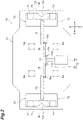
FIG. 2] FIG. 2 is a plan view of the gripper device inFIG. 1 . - [
FIG. 3] FIG. 3 is a perspective view of an article to be carried by a conveyance vehicle system ofFIG. 1 . - [
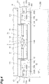
FIG. 4] FIG. 4 is a diagram of the gripper device viewed from a side, indicating a state where a pair of engaging portions are located in a standby position. - [
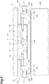
FIG. 5] FIG. 5 is a diagram of the gripper device viewed from the side, indicating a state where the pair of engaging portions are located in an engaging position. - [
FIG. 6] FIG. 6 is a plan view indicating a state where the engaging portion engages with the held portion. - [
FIG. 7] FIG. 7 is a cross-sectional view along VII-VII line ofFIG. 6 . - [
FIG. 8] FIG. 8 is an enlarged view of a part ofFIG. 5 . - [
FIG. 9] FIG. 9 is a diagram indicating a state where one of the held portions is held when the other of the held portions is damaged. - As illustrated in
FIG. 1 , an overhead conveyance vehicle (conveyance vehicle) 1 of one embodiment travels along atrack 100 laid on aceiling 110 of a clean room where semiconductor devices are manufactured. Theoverhead conveyance vehicle 1 of the one embodiment carries front opening unified pod (FOUP) (article) 200 accommodating a plurality of semiconductor wafers, and transfers the FOUP 200 to aload port 300 or the like that is a transfer section provided in a processing device that performs various types of processing on the semiconductor wafers. Thetrack 100 is suspended from theceiling 110 by asuspension column 108. Thetrack 100 has atraveling rail 101 and afeeder rail 102 that is provided at a lower part of thetraveling rail 101. - The
overhead conveyance vehicle 1 includes aframe unit 2, atraveling unit 3a, apower receiving unit 3b, alateral unit 4, an angle adjustment unit 5, anelevating drive unit 6, agripper device 10, and acontroller 8. Theframe unit 2 has acenter frame 21, afront frame 22, and arear frame 23. Thefront frame 22 extends downward from an end of a front side (front side in a travel direction of the overhead conveyance vehicle 1) in thecenter frame 21 to a lower side thereof. Therear frame 23 extends downward from an end of a rear side (rear side in the travel direction of the overhead conveyance vehicle 1) in thecenter frame 21 to the lower side thereof. - The
traveling unit 3a and thepower receiving unit 3b are disposed on the upper side of thecenter frame 21. Thetraveling unit 3a is attached to thetraveling rail 101. Thepower receiving unit 3b receives, for example, power supply in a noncontact manner from a high-frequency current line laid along thefeeder rail 102. The power supply to the power receivingunit 3b causes thetraveling unit 3a to travel along thetrack 100. Thelateral unit 4 is disposed on the lower side of thecenter frame 21. Thelateral unit 4 moves the angle adjustment unit 5, the elevatingdrive unit 6, and thegripper device 10 to move laterally (side in the travel direction of the overhead conveyance vehicle 1). The angle adjustment unit 5 is disposed on a lower side of thelateral unit 4. The angle adjustment unit 5 rotates the elevatingdrive unit 6 and thegripper device 10 in a horizontal plane. - The elevating
drive unit 6 is disposed on the lower side of the angle adjustment unit 5. The elevatingdrive unit 6 lifts and lowersgripper device 10. Thegripper device 10 is disposed on the lower side of the elevatingdrive unit 6. Thegripper device 10 holds a flange section (held portion) 202 of theFOUP 200. Thecontroller 8 is disposed on thefront frame 22 and therear frame 23. Thecontroller 8 is an electronic control unit including a CPU, ROM, and RAM. Thecontroller 8 controls each part of theoverhead conveyance vehicle 1. - To the
front frame 22 and therear frame 23, four lowerdrop preventing sections 26 and two liddrop preventing sections 27 that each prevent theFOUP 200 from dropping from theframe unit 2 are attached. The lowerdrop preventing sections 26 are correspondingly attached to the lower end of thefront frame 22 and the lower end of therear frame 23 at the four corner positions of theframe unit 2 and correspondingly face the front end and the rear end of the bottom of theFOUP 200. The liddrop preventing sections 27 are attached to the lower part of thefront frame 22 and the lower part of therear frame 23, respectively, and face theFOUP 200 from thelid 205 side (seeFIG. 3 ). These lowerdrop preventing sections 26 and the liddrop preventing sections 27 are opened and closed at appropriate timing in association with transfer of theFOUP 200. - The
overhead conveyance vehicle 1 configured as described above operates, as an example, described below. When theFOUP 200 is transferred from aload port 300 to theoverhead conveyance vehicle 1, theoverhead conveyance vehicle 1 that does not hold theFOUP 200 stops above theload port 300. When a horizontal position of thegripper device 10 deviates from the position directly above theload port 300, the horizontal position and an angle of a holding unit are fine-tuned by driving thelateral unit 4 and the angle adjustment unit 5 to fine-tune the whole elevatingdrive unit 6. Subsequently, the elevatingdrive unit 6 lowers thegripper device 10, and thegripper device 10 holds theflange section 202 of theFOUP 200 that is placed on theload port 300. The elevatingdrive unit 6 then lifts thegripper device 10 to a lifting end and disposes theFOUP 200 between thefront frame 22 and therear frame 23. The lowerdrop preventing sections 26 and the liddrop preventing sections 27 are closed. Theoverhead conveyance vehicle 1 holding theFOUP 200 then begins traveling. - When the
FOUP 200 is transferred from theoverhead conveyance vehicle 1 to theload port 300, theoverhead conveyance vehicle 1 holding theFOUP 200 stops above theload port 300. The lowerdrop preventing section 26 and the liddrop preventing section 27 are opened. When the horizontal position of the gripper device 10 (FOUP 200) deviates from a position directly above theload port 300, the horizontal position and the angle of the holding unit are fine-tuned by driving thelateral unit 4 and the angle adjustment unit 5 to fine-tune the whole elevatingdrive unit 6. Subsequently, the elevatingdrive unit 6 lowers thegripper device 10 to place theFOUP 200 on theload port 300, and thegripper device 10 releases its holding of theflange section 202 of theFOUP 200. The elevatingdrive unit 6 then lifts thegripper device 10 to the lifting end thereof. Theoverhead conveyance vehicle 1 that does not hold theFOUP 200, then begins traveling. - As illustrated in
FIG. 2 , thegripper device 10 includes an elevatingsection 11 that forms a body of thegripper device 10, amotor 16 fixed to the elevatingsection 11, asingle link mechanism 20 connected to themotor 16 via anoutput shaft 16a of themotor 16, and a pair of finger sections (engaging portions) 12 attached to respective tips of thelink mechanism 20. Themotor 16, thelink mechanism 20, and the pair offinger sections 12 are attached to the elevatingsection 11. Themotor 16 and thelink mechanism 20 are included in thedrive section 7 that moves the pair offinger sections 12. The elevatingsection 11 is suspended by, for example, fourbelts 6a that are included in the elevatingdrive unit 6 described above. The elevatingsection 11 is capable of lifting and lowering above the FOUP 200 (above the load port 300) when the elevatingdrive unit 6 is controlled by thecontroller 8. It should be noted that the elevatingdrive unit 6 may have threebelts 6a and the elevatingsection 11 may be suspended by the threebelts 6a. - Referring to
FIG. 3 , theFOUP 200 held by thegripper device 10 of the present embodiment is described. TheFOUP 200 has abody 201 having a rectangular parallelepiped shape, for example. Alid 205 is attached to a side face of the body 201 (a surface of a side in the travel direction of the overhead conveyance vehicle 1) so as to be opened and closed freely. TheFOUP 200 accommodates a plurality of semiconductor wafers in thebody 201. TheFOUP 200 may accommodate a plurality of semiconductor panels that each are a rectangular-shaped substrate, within thebody 201. Atop surface 201a, having a rectangular shape, of thebody 201 is provided with a pair offlange sections 202 that are held by thegripper device 10. The pair offlange sections 202 are spaced apart in a direction along thetop surface 201a and corresponding to the travel direction of the overhead conveyance vehicle 1 (X direction indicated in the figure). In the following description, this direction is referred to as a "first direction". The pair offlange sections 202 are disposed at ends 201b and 201b in an X direction of thetop surface 201a and each extend long in a direction along thetop surface 201a and orthogonal to the above-described first direction (Y direction indicated in the figure). In the following description, a direction orthogonal to this first direction is referred to as a "second direction". These terms of the first direction and the second direction may be used to describe theFOUP 200, and may also be used to describe thegripper device 10 that holds theFOUP 200. As described above, the first direction corresponds to the travel direction of theoverhead conveyance vehicle 1 in a state where the elevatingdrive unit 6 and thegripper device 10 are aligned with theframe unit 2. - More specifically, a plurality of pairs (three pairs in the present embodiment) of
columns 203 are erected on thetop surface 201a of theFOUP 200 at each of theends columns 203 are spaced apart in the Y direction, and aligned in the Y direction, for example. Each of thecolumns 203 extends perpendicular to thetop surface 201a, and its lower end is fixed to thetop surface 201a. At oneend 201b in the first direction of thetop surface 201a, three equal-length columns 203, for example, are erected, and one plate of theflange section 202 is fixed to the upper end of each of thesecolumns 203 by welding or bolts. Each of theflange sections 202 is, for example, a long plate-like member that is disposed parallel to thetop surface 201a and extends in the Y direction. At theother end 201b in the first direction of thetop surface 201a, for example, threecolumns 203 having an equal length are erected, and one plate of theflange section 202 is fixed to the upper end of each of thesecolumns 203 by welding or bolts. The pair offlange sections 202 extend parallel, for example, to thetop surface 201a of theFOUP 200. As explained above, theFOUP 200 has the pair offlange sections 202 provided on thetop surface 201a and spaced apart in the first direction along thetop surface 201a. - When the
column 203 is provided, a predetermined space is formed between thetop surface 201a and theflange section 202. As illustrated inFIG. 1 , the pair offlange sections 202 fall within a length of thebody 201 in the first direction (the overall length of the FOUP 200). Thefinger section 12 of thegripper device 10 is inserted into a space between thetop surface 201a and theflange section 202, from the center of thetop surface 201a to theend 201b. TheFOUP 200 is an article that is held (supported) from below by thefinger section 12 that is moved from inside to outside and inserted into the above-described space. - Referring to
FIGS. 2 ,4 , and5 , thegripper device 10 is described in detail. The pair offinger sections 12 of thegripper device 10 move along the first direction (X direction indicated in the figure). The pair offinger sections 12 are supported by the elevatingsection 11 so as to be able to move (slide) horizontally in thegripper device 10. When thegripper device 10 holds theFOUP 200, thefinger sections 12 advance to be closer to theflange section 202. When thegripper device 10 releases its holding of theFOUP 200, thefinger sections 12 retreat so as to be away from theflange section 202. - As illustrated in
FIGS. 2 and4 , thelink mechanism 20 is a mechanism for moving thefinger section 12. Thelink mechanism 20 includes: a singlecentral link 17 that is connected to theoutput shaft 16a of themotor 16 and rotates about theoutput shaft 16a; a pair offirst links 18 the first ends of which are rotatably connected to a pair ofshafts 17a provided at both ends of thecentral link 17; and a pair ofsecond links 19 the base ends of which are rotatably connected to a pair ofshafts 18a provided at the second ends of thefirst links 18. As illustrated inFIGS. 4 and5 , as theoutput shaft 16a rotates, thecentral link 17 rotates, and one of thefirst links 18 and one of thesecond links 19 and the other of thefirst links 18 and the other of thesecond links 19 move synchronously. Thefinger section 12 is attached to the tip of each of the pair ofsecond links 19. - As illustrated in
FIG. 2 , thefinger section 12 includes an engagingplate 13 that is rectangular in plan view. This engagingplate 13 is inserted into the space between thetop surface 201a of theFOUP 200 and theflange section 202, and supports theflange section 202 from below. The pair offinger sections 12 of thegripper device 10 engage with the pair offlange sections 202 of theFOUP 200. - More specifically, as illustrated in
FIGS. 6 and7 , the engagingplate 13 includes athick plate section 13a attached to the tip of thesecond link 19 and athin plate section 13b formed on the tip side of thethick plate section 13a. As illustrated inFIG. 7 , thethin plate section 13b is thinner than thethick plate section 13a. A bottom surface of thethin plate section 13b is flush with a bottom surface of thethick plate section 13a, but a top surface of thethin plate section 13b is formed at a position lower than a top surface of thethick plate section 13a, and a single sheet offirst buffer member 14 and two sheets ofsecond buffer members 15 having predetermined thicknesses are affixed to the top surface of thisthin plate section 13b. Thefirst buffer member 14 and thesecond buffer members 15 are, for example, resin members. Thesecond buffer members 15 having a rectangular shape are affixed to both ends of thethin plate section 13b in the second direction, and thefirst buffer member 14 having a rectangular shape is affixed between thesecond buffer members 15. - The position where the
second buffer member 15 is affixed corresponds to the position of thecenter column 203 of the threecolumns 203 erected on theFOUP 200. Thethin plate section 13b and thefirst buffer member 14 have triangular notches having substantially equal sizes and shapes formed therein. Accordingly, anotch 12a that accepts thecenter column 203 is formed in thefinger section 12. Thenotch 12a is, for example, a V-shaped depression containing two oblique edges and is open at atip 12b of thefinger section 12 in the X direction thereof. The length of the engagingplate 13 in the Y direction is shorter than the interval between thecolumns 203 located at both ends. In a state where thenotch 12a in thefinger section 12 accepts the central column 203 (i.e., thecentral column 203 fits in thenotch 12a), thefinger section 12 is disposed between thecolumns 203 located at both ends (seeFIG. 6 ). - Referring again to
FIGS. 4 and5 , the range of movement of thefinger section 12 is explained. Thedrive section 7 moves the pair offinger sections 12 along the first direction between a standby position P1 (seeFIG. 4 ), where the distance between the pair offinger sections 12 is shorter than the interval between the pair offlange sections 202, and an engaging position P2, where the pair offinger sections 12 is capable of engaging with theflange sections 202. This engaging position P2 is a position such that the distance between the pair offinger sections 12 is longer than the interval between the pair offlange sections 202. In the present embodiment, with thelink mechanism 20, the pair offinger sections 12 move linearly. The "distance between a pair offinger sections 12" means a distance between thetips 12b of thefinger sections 12 indicated inFIG. 4 . The "interval between the pair offlange sections 202" means the distance between inner ends 202b in the first direction of the pair offlange sections 202 indicated inFIG. 4 . - In other words, the
drive section 7 moves the pair offinger sections 12 along the first direction from the standby position P1 to the engaging position P2 such that the pair offinger sections 12 are separated from one another. In other words, thedrive section 7 moves the pair offinger sections 12 from inside (closer to the center of the elevating section 11) to outside (closer to thefront frame 22 and rear frame 23) of the elevatingsection 11. Thus, thedrive section 7 extends and deploys the pair offinger sections 12. Thedrive section 7 moves the pair offinger sections 12 along the first direction from the engaging position P2 to the standby position P1 such that the pair offinger sections 12 are closer to each other. In other words, thedrive section 7 moves the pair offinger sections 12 from outside (closer to thefront frame 22 and rear frame 23) to inside (closer to the center of the elevating section 11) of the elevatingsection 11. Thus, thedrive section 7 retracts and stores the pair offinger sections 12. - Furthermore, the
gripper device 10 in the present embodiment includes adrop preventing section 30 that prevents theFOUP 200 from dropping in a case where the device (theFOUP 200 or the finger section 12) is damaged. As illustrated inFIGS. 2 and5 , a pair of thedrop preventing sections 30 are fixed to both ends of the elevatingsection 11 in the first direction. The pair ofdrop preventing sections 30 are disposed so as to be spaced apart in the first direction with an interval longer than the interval between the pair offlange sections 202. More specifically, the pair ofdrop preventing sections 30 are spaced apart in the first direction by an interval longer than the distance betweenouter ends 202a (seeFIG. 8 ) of the pair offlange sections 202 in the first direction. Each of thedrop preventing sections 30 includes a hangingplate 31 that hangs from the elevatingsection 11. Alower end 31a of the hangingplate 31 is located at a lower height than theflange section 202 in a state where thegripper device 10 is lowered and the height of thegripper device 10 with respect to theFOUP 200 is adapted. More specifically, in a state where thefinger section 12 engages with theflange section 202 and thegripper device 10 holds the FOUP 200 (the state indicated inFIGS. 5 and8 ), thelower end 31a of the hangingplate 31 is at a lower height than theflange section 202, and aninner surface 31b of the hangingplate 31 faces theouter end 202a of theflange section 202 with a predetermined gap. - As illustrated in
FIG. 4 , a first gap G1 is formed between each of the pair ofdrop preventing sections 30 and each of the pair offinger sections 12 located at the standby position P1, the first gap G1 allowing each of the pair offlange sections 202 to vertically pass therethrough. As illustrated inFIG. 8 , a second gap G2 is formed between each of the pair ofdrop preventing sections 30 and each of the pair offinger sections 12 located at the engaging position P2, the second gap G2 not allowing each of the pair offlange sections 202 to pass vertically therethrough. The first gap G1 and the second gap G2 may be defined as a distance between thetip 12b of thefinger section 12 and theinner surface 31b of the hangingplate 31. The first gap G1 is larger than theflange section 202 in size in the first direction. The second gap G2 is smaller than theflange section 202 in size in the first direction. - The following describes the conveyance method of the
FOUP 200 by theoverhead conveyance vehicle 1 including thegripper device 10 of the present embodiment. Each of the following operations is performed based on control by thecontroller 8. First, in a state where the horizontal position of thegripper device 10 is located directly above theload port 300, the elevatingsection 11 is lowered (lowering step). In this lowering step, positioning of thegripper device 10 in the height direction and the horizontal direction relative to theFOUP 200 is performed using known positioning means or the like provided in the elevatingsection 11. Then, thedrive section 7 moves the pair offinger sections 12 along the first direction from the standby position P1, where the distance between the pair offinger sections 12 is shorter than the interval between the pair offlange sections 202, to the engaging position P2, where the pair offinger sections 12 is capable of engaging with the flange sections 202 (for the moving step, seeFIGS. 4 and5 ). This step allows thecenter column 203 to enter thenotch 12a in thefinger section 12, and thefinger section 12 to be inserted into the bottom surface side of theflange section 202. Furthermore, the elevatingsection 11 is lifted and the pair offinger sections 12 at the engaging position P2 engage with the pair offlange sections 202, and theFOUP 200 is held by the gripper device 10 (holding step). - According to the
gripper device 10 of the present embodiment, the pair offinger sections 12 attached to the elevatingsection 11 is moved by themotor 16 from the standby position P1 to the engaging position P2. Thetop surface 201a of theFOUP 200 is provided with a pair offlange sections 202 spaced apart in the first direction. The pair offinger sections 12 are disposed between (inside) these pairs offlange sections 202 when thegripper device 10 is to hold theFOUP 200, and are moved from inside to outside of theFOUP 200 along the first direction above. This arrangement of thefinger sections 12 and their movement and engagement in the first direction makes thegripper device 10 compact as a whole. According to thisgripper device 10, an article is able to be held in the compact configuration. - Since only one
link mechanism 20 is used to move a pair offinger sections 12, the structure is simpler than when multiple link mechanisms are used. In addition, since a singlecommon link mechanism 20 is provided for the pair offinger sections 12, the movements of the pair offinger sections 12 is able to be easily synchronized. - When the elevating
section 11 is lowered in a state where the pair offinger sections 12 are located at the standby position P1, theflange section 202 passes through the first gap G1 between thefinger section 12 and thedrop preventing section 30 in each of both end regions in the first direction (seeFIG. 4 ). When the pair offinger sections 12 are moved to the engaging position P2 to engage with the pair offlange sections 202, theflange sections 202 are not able to pass through the second gap G2 between thefinger section 12 and thedrop preventing section 30 in each of both end regions in the first direction (seeFIG. 5 ). For example, as illustrated inFIG. 9 , even if the first flange section 202 (or the first finger section 12) is damaged due to some unforeseen event, thesecond flange section 202 is held and maintained between thesecond finger section 12 and the seconddrop preventing section 30. Thus, either one of the engagement structures can be maintained, and theFOUP 200 can be held and theFOUP 200 is able to be prevented from dropping. - When a proper engagement structure for the
flange section 202 is not provided in any of the finger sections 12 (in a case as exemplified inFIG. 9 ), thecontroller 8 may detect absence of theflange section 202, upon receiving a signal from a known sensor (called a presence sensor or the like) installed in a positioning section of the elevatingsection 11, for example. Thecontroller 8, upon detecting absence of theflange section 202, may generate an alarm or inform the operator of the absence. With this approach, it is possible to detect not only the absence of theflange section 202, but also damage to thefinger section 12. - When the
column 203 is provided on theFOUP 200, a space into which thefinger section 12 is inserted is able to be easily formed between thetop surface 201a of theFOUP 200 and theflange section 202. Thecolumn 203 serves as a spacer, so to speak. In the movement of thefinger section 12 in the first direction, it is possible to perform control, for example, to make part of thefinger section 12 contact thecolumn 203 from the inside. In such a case, thefinger section 12 is able to be positioned securely and easily. - According to the
overhead conveyance vehicle 1 of the present embodiment, since thegripper device 10 has the compact configuration, theoverhead conveyance vehicle 1 is able to be made compact and lightweight relative to theFOUP 200 in the size, the weight, and the like. - According to the above-described conveyance method of the present embodiment, the same actions and effects as those of the
overhead conveyance vehicle 1 andgripper device 10 described above are achieved. In other words, in the holding step, theFOUP 200 is able to be held in the compact configuration. Thegripper device 10 has the compact configuration, and is able to make use of the advantage that the device is compact and light weight when carrying the heldFOUP 200. For example, the conveyance method of the present embodiment is also advantageous in terms of providing faster carrying speeds and reducing power consumption. - Although the embodiment of the present disclosure has been described above, the invention is not limited to the above-described embodiment. For example, either one or both of the lower
drop preventing section 26 and the liddrop preventing section 27 may be omitted. Not limited to cases where the plurality of pairs ofcolumns 203 are erected on thetop surface 201a of theFOUP 200, only one pair of the pairs ofcolumns 203 may be erected on thetop surface 201a of theFOUP 200. In other words, thecolumns 203 at both ends in the Y direction may be omitted. In such a case, thecolumn 203 may be erected in substantially the center of theflange section 202 in an extending direction. The pair offlange sections 202 may be somewhat beyond the length of thebody 201 in the first direction (the overall length of the FOUP 200). - It is not limited to cases where the
drive section 7 has only onelink mechanism 20. Thefirst finger section 12 andsecond finger section 12 may be driven separately. Each of the finger sections may be driven by a ball screw, a belt, or the like, for example, instead of the link mechanism. - The pair of engaging portions may be moved along the
top surface 201a of theFOUP 200 in a direction that is linear and at an angle to the first direction. It is not limited to the case where the pair of engaging portions are moved linearly by the drive section, but the pair of engaging portions may be moved along thetop surface 201a of theFOUP 200 in a zigzag manner, for example. The pair of engaging portions may be moved along thetop surface 201a of theFOUP 200 in a curved shape, for example. - An article is not limited to the
FOUP 200. The article may be a standard mechanical interface (SMIF) pod or a front opening shipping box (FOSB), or the like. -
- 1
- Overhead conveyance vehicle (conveyance vehicle)
- 7
- Drive section
- 10
- Gripper device
- 11
- Elevating section
- 12
- Finger section (engaging portion)
- 13
- Engaging plate
- 14
- First buffer member
- 15
- Second buffer member
- 16
- Motor
- 20
- Link mechanism
- 200
- FOUP (article)
- 201
- Body
- 201a
- Top surface
- 202
- Flange section (held portion)
- 203
- Column
- 300
- Load port
- P1
- Standby position
- P2
- Engaging position
Claims (6)
- A gripper device that holds an article having a pair of held portions that are provided on a top surface of the article and that are spaced apart in a direction along the top surface, the gripper device comprising:a pair of engaging portions that are attached to an elevating section capable of lifting and lowering above the article and that respectively engage with the pair of held portions; anda drive section that moves the pair of engaging portions along the direction, from a standby position where a distance between the pair of engaging portions is shorter than an interval between the pair of held portions to an engaging position where the pair of engaging portions is capable of engaging with the pair of held portions, such that the pair of engaging portions separate from one another.
- The gripper device according to claim 1, whereinthe gripper device includes a pair of drop preventing sections that are fixed to the elevating section and disposed to be spaced apart in the direction with a longer interval than the interval,a first gap is formed correspondingly between each of the pair of drop preventing sections and each of the pair of engaging portions located at the standby position, the first gap allowing each of the pair of held portions to vertically pass therethrough, anda second gap is formed correspondingly between each of the pair of drop preventing sections and each of the pair of engaging portions located at the engaging position, the second gap not allowing each of the pair of held portions to vertically pass therethrough.
- The gripper device according to claim 1 or 2, whereinthe article is provided with at least a pair of columns erected on the top surface of the article and the pair of held portions fixed to the columns, andeach of the pair of engaging portions has a notch that accepts the column when the pair of engaging portions are located in the engaging position.
- The gripper device according to any one of claims 1 to 3, wherein the drive section has a single link mechanism configured to move the pair of engaging portions.
- A conveyance vehicle that includes the gripper device according to any one of claims 1 to 4 and travels along a track provided on a ceiling.
- A conveyance method for holding and carrying, with a gripper device, an article with a pair of held portions that are provided on a top surface of the article and spaced apart in a direction along the top surface, whereinthe gripper device includes a pair of engaging portions attached to an elevating section capable of lifting and lowering above the article and that respectively engage with the pair of held portions,the conveyance method comprising:a lowering step for lowering the elevating section;a moving step for moving the pair of engaging portions along the direction, from a standby position where a distance between the pair of engaging portions is shorter than an interval between the pair of held portions to an engaging position where the pair of engaging portions is capable of engaging with the pair of held portions; anda holding step for holding the article by causing the elevating section to lift and causing the pair of engaging portions in the engaging position to engage with the pair of held portions.
Applications Claiming Priority (2)
| Application Number | Priority Date | Filing Date | Title |
|---|---|---|---|
| JP2020044629 | 2020-03-13 | ||
| PCT/JP2021/002788 WO2021181923A1 (en) | 2020-03-13 | 2021-01-27 | Gripper device, conveyance vehicle, and conveyance method |
Publications (2)
| Publication Number | Publication Date |
|---|---|
| EP4109502A1 true EP4109502A1 (en) | 2022-12-28 |
| EP4109502A4 EP4109502A4 (en) | 2024-05-01 |
Family
ID=77671362
Family Applications (1)
| Application Number | Title | Priority Date | Filing Date |
|---|---|---|---|
| EP21768710.2A Pending EP4109502A4 (en) | 2020-03-13 | 2021-01-27 | GRIPPER, TRANSPORT VEHICLE AND TRANSPORT METHOD |
Country Status (8)
| Country | Link |
|---|---|
| US (1) | US12139176B2 (en) |
| EP (1) | EP4109502A4 (en) |
| JP (1) | JP7367845B2 (en) |
| KR (1) | KR102700084B1 (en) |
| CN (1) | CN115280482B (en) |
| IL (1) | IL296295B1 (en) |
| TW (1) | TWI836195B (en) |
| WO (1) | WO2021181923A1 (en) |
Families Citing this family (6)
| Publication number | Priority date | Publication date | Assignee | Title |
|---|---|---|---|---|
| JP2023070578A (en) * | 2021-11-09 | 2023-05-19 | ゴールド工業株式会社 | Substrate storage container |
| TWI823487B (en) * | 2022-02-17 | 2023-11-21 | 盟立自動化股份有限公司 | Rail switching mechanism and transfer system of overhead hoist transfer |
| JP7480797B2 (en) * | 2022-03-14 | 2024-05-10 | 村田機械株式会社 | Overhead transport vehicle system |
| JP7745522B2 (en) * | 2022-08-30 | 2025-09-29 | 株式会社ダイフク | Transport vehicle |
| JP2024150068A (en) * | 2023-04-10 | 2024-10-23 | 株式会社ダイフク | Transport vehicle |
| KR102907269B1 (en) * | 2023-04-24 | 2026-01-05 | 한국항공우주산업 주식회사 | A method and system for transferring an assembly by using an AGV |
Family Cites Families (30)
| Publication number | Priority date | Publication date | Assignee | Title |
|---|---|---|---|---|
| US3438510A (en) * | 1967-09-26 | 1969-04-15 | Joseph E Fawell | Wheel handling apparatus |
| DE19806231C1 (en) * | 1998-02-16 | 1999-07-22 | Jenoptik Jena Gmbh | Device for gripping an object by a gripping component with interacting adjustable gripping components |
| US6481558B1 (en) * | 1998-12-18 | 2002-11-19 | Asyst Technologies, Inc. | Integrated load port-conveyor transfer system |
| JP4277182B2 (en) | 2003-06-30 | 2009-06-10 | オリエンタル工業株式会社 | Silicon wafer cleaning equipment |
| JP2005026594A (en) * | 2003-06-30 | 2005-01-27 | Resuka:Kk | Peel test method for solid samples adhered or embedded on a substrate |
| JP2006008355A (en) * | 2004-06-28 | 2006-01-12 | Murata Mach Ltd | Overhead traveling car |
| JP2007096140A (en) * | 2005-09-30 | 2007-04-12 | Asyst Shinko Inc | Method and apparatus for receiving and receiving articles in a suspended lift carriage |
| JP2007123673A (en) * | 2005-10-31 | 2007-05-17 | Asyst Shinko Inc | Anti-vibration mechanism for container for storing goods |
| JP2011035022A (en) | 2009-07-30 | 2011-02-17 | Murata Machinery Ltd | Overhead carrier |
| EP2452898B1 (en) * | 2009-11-27 | 2016-12-07 | Daifuku Co., Ltd. | Ceiling conveyor car |
| KR101169734B1 (en) * | 2010-01-04 | 2012-07-30 | 삼성전기주식회사 | Apparatus of transferring substrate |
| KR20120003368A (en) * | 2010-07-02 | 2012-01-10 | 무라텍 오토메이션 가부시키가이샤 | Gripper device of ceiling carrier and ceiling carrier |
| JP5750926B2 (en) * | 2011-02-15 | 2015-07-22 | 村田機械株式会社 | Ceiling transport vehicle |
| KR101523537B1 (en) * | 2011-05-17 | 2015-05-28 | 무라다기카이가부시끼가이샤 | Overhead transport carriage |
| CH705297A1 (en) * | 2011-07-21 | 2013-01-31 | Tecan Trading Ag | Gripping pliers with interchangeable gripper fingers. |
| JP2013045964A (en) * | 2011-08-25 | 2013-03-04 | Sharp Corp | Immersion processing method of substrate to be processed and immersion processing device |
| JP5590420B2 (en) * | 2011-12-21 | 2014-09-17 | 株式会社ダイフク | Goods transport equipment |
| JP5567095B2 (en) * | 2012-10-12 | 2014-08-06 | 東芝エレベータ株式会社 | Elevator equipment |
| JP6136775B2 (en) * | 2013-08-30 | 2017-05-31 | 株式会社ダイフク | Transport device |
| JP6179406B2 (en) * | 2014-01-10 | 2017-08-16 | 株式会社ダイフク | Transport device |
| JP6171984B2 (en) * | 2014-03-07 | 2017-08-02 | 株式会社ダイフク | Article support device |
| JP6064940B2 (en) * | 2014-04-07 | 2017-01-25 | 株式会社ダイフク | Goods transport vehicle |
| JP6327124B2 (en) * | 2014-11-12 | 2018-05-23 | 株式会社ダイフク | Goods transport vehicle |
| JP6414134B2 (en) * | 2016-05-09 | 2018-10-31 | 村田機械株式会社 | Transport device |
| JP6702106B2 (en) * | 2016-09-09 | 2020-05-27 | 株式会社ダイフク | Article carrier |
| JP6607175B2 (en) | 2016-12-07 | 2019-11-20 | 株式会社ダイフク | Transfer machine |
| JP6801476B2 (en) * | 2017-02-01 | 2020-12-16 | 村田機械株式会社 | Ceiling carrier |
| CN110612258B (en) * | 2017-05-11 | 2021-06-15 | 村田机械株式会社 | Conveying system and conveying method |
| EP3670389B1 (en) * | 2017-08-16 | 2024-05-15 | Murata Machinery, Ltd. | Overhead transport vehicle, overhead transport system, and control method for overhead transport vehicle |
| WO2019146276A1 (en) * | 2018-01-24 | 2019-08-01 | 村田機械株式会社 | Transport vehicle |
-
2021
- 2021-01-27 WO PCT/JP2021/002788 patent/WO2021181923A1/en not_active Ceased
- 2021-01-27 KR KR1020227035075A patent/KR102700084B1/en active Active
- 2021-01-27 CN CN202180019863.1A patent/CN115280482B/en active Active
- 2021-01-27 EP EP21768710.2A patent/EP4109502A4/en active Pending
- 2021-01-27 JP JP2022505822A patent/JP7367845B2/en active Active
- 2021-01-27 IL IL296295A patent/IL296295B1/en unknown
- 2021-01-27 US US17/910,384 patent/US12139176B2/en active Active
- 2021-03-10 TW TW110108535A patent/TWI836195B/en active
Also Published As
| Publication number | Publication date |
|---|---|
| WO2021181923A1 (en) | 2021-09-16 |
| US12139176B2 (en) | 2024-11-12 |
| TW202139338A (en) | 2021-10-16 |
| EP4109502A4 (en) | 2024-05-01 |
| TWI836195B (en) | 2024-03-21 |
| IL296295A (en) | 2022-11-01 |
| KR20220150967A (en) | 2022-11-11 |
| CN115280482B (en) | 2025-07-04 |
| CN115280482A (en) | 2022-11-01 |
| US20230134312A1 (en) | 2023-05-04 |
| JP7367845B2 (en) | 2023-10-24 |
| KR102700084B1 (en) | 2024-08-27 |
| IL296295B1 (en) | 2026-02-01 |
| JPWO2021181923A1 (en) | 2021-09-16 |
Similar Documents
| Publication | Publication Date | Title |
|---|---|---|
| US12139176B2 (en) | Gripper device, conveyance vehicle, and conveyance method | |
| US10593583B2 (en) | Integrated systems for interfacing with substrate container storage systems | |
| EP2433299B1 (en) | Substrate container storage system | |
| CN115280483B (en) | Gripper device, transport vehicle, and transport method | |
| JP5234328B2 (en) | Goods storage equipment | |
| EP2554494B1 (en) | Side buffer for a transport vehicle that travels along the ceiling, and transport vehicle system | |
| JP5083278B2 (en) | Automatic warehouse in front of equipment | |
| KR20120050931A (en) | Integrated systems for interfacing with substrate container storage system | |
| TWI743169B (en) | Article transport device | |
| KR102583574B1 (en) | Carriage robot and tower lift including the same | |
| WO2018186021A1 (en) | Ceiling transport vehicle system and teaching unit | |
| KR101770161B1 (en) | Tray transferring apparatus | |
| EP1801869A1 (en) | Container carrying equipment | |
| TW201348100A (en) | Transport system | |
| KR101940017B1 (en) | Tray transferring apparatus | |
| KR102356962B1 (en) | Transfer machine | |
| KR100965512B1 (en) | Flat panel display device manufacturing device | |
| CN110525977B (en) | Lifting and transporting mechanism and lifting and transporting equipment | |
| JP2024150068A (en) | Transport vehicle | |
| KR20220060485A (en) | Transport vehicle | |
| JP2010098041A (en) | Conveyance system |
Legal Events
| Date | Code | Title | Description |
|---|---|---|---|
| STAA | Information on the status of an ep patent application or granted ep patent |
Free format text: STATUS: THE INTERNATIONAL PUBLICATION HAS BEEN MADE |
|
| PUAI | Public reference made under article 153(3) epc to a published international application that has entered the european phase |
Free format text: ORIGINAL CODE: 0009012 |
|
| STAA | Information on the status of an ep patent application or granted ep patent |
Free format text: STATUS: REQUEST FOR EXAMINATION WAS MADE |
|
| 17P | Request for examination filed |
Effective date: 20220922 |
|
| AK | Designated contracting states |
Kind code of ref document: A1 Designated state(s): AL AT BE BG CH CY CZ DE DK EE ES FI FR GB GR HR HU IE IS IT LI LT LU LV MC MK MT NL NO PL PT RO RS SE SI SK SM TR |
|
| DAV | Request for validation of the european patent (deleted) | ||
| DAX | Request for extension of the european patent (deleted) | ||
| A4 | Supplementary search report drawn up and despatched |
Effective date: 20240403 |
|
| RIC1 | Information provided on ipc code assigned before grant |
Ipc: H01L 21/673 20060101ALN20240326BHEP Ipc: H01L 21/687 20060101ALI20240326BHEP Ipc: H01L 21/677 20060101AFI20240326BHEP |