EP4109074A1 - Particle analysis device - Google Patents
Particle analysis device Download PDFInfo
- Publication number
- EP4109074A1 EP4109074A1 EP21756875.7A EP21756875A EP4109074A1 EP 4109074 A1 EP4109074 A1 EP 4109074A1 EP 21756875 A EP21756875 A EP 21756875A EP 4109074 A1 EP4109074 A1 EP 4109074A1
- Authority
- EP
- European Patent Office
- Prior art keywords
- electrode
- liquid
- hole
- rod
- analysis device
- Prior art date
- Legal status (The legal status is an assumption and is not a legal conclusion. Google has not performed a legal analysis and makes no representation as to the accuracy of the status listed.)
- Withdrawn
Links
Images





Classifications
-
- G—PHYSICS
- G01—MEASURING; TESTING
- G01N—INVESTIGATING OR ANALYSING MATERIALS BY DETERMINING THEIR CHEMICAL OR PHYSICAL PROPERTIES
- G01N15/00—Investigating characteristics of particles; Investigating permeability, pore-volume or surface-area of porous materials
- G01N15/10—Investigating individual particles
- G01N15/1031—Investigating individual particles by measuring electrical or magnetic effects
- G01N15/12—Investigating individual particles by measuring electrical or magnetic effects by observing changes in resistance or impedance across apertures when traversed by individual particles, e.g. by using the Coulter principle
-
- G—PHYSICS
- G01—MEASURING; TESTING
- G01N—INVESTIGATING OR ANALYSING MATERIALS BY DETERMINING THEIR CHEMICAL OR PHYSICAL PROPERTIES
- G01N27/00—Investigating or analysing materials by the use of electric, electrochemical, or magnetic means
- G01N27/26—Investigating or analysing materials by the use of electric, electrochemical, or magnetic means by investigating electrochemical variables; by using electrolysis or electrophoresis
- G01N27/416—Systems
- G01N27/447—Systems using electrophoresis
- G01N27/44756—Apparatus specially adapted therefor
-
- B—PERFORMING OPERATIONS; TRANSPORTING
- B01—PHYSICAL OR CHEMICAL PROCESSES OR APPARATUS IN GENERAL
- B01L—CHEMICAL OR PHYSICAL LABORATORY APPARATUS FOR GENERAL USE
- B01L3/00—Containers or dishes for laboratory use, e.g. laboratory glassware; Droppers
- B01L3/50—Containers for the purpose of retaining a material to be analysed, e.g. test tubes
- B01L3/502—Containers for the purpose of retaining a material to be analysed, e.g. test tubes with fluid transport, e.g. in multi-compartment structures
- B01L3/5027—Containers for the purpose of retaining a material to be analysed, e.g. test tubes with fluid transport, e.g. in multi-compartment structures by integrated microfluidic structures, i.e. dimensions of channels and chambers are such that surface tension forces are important, e.g. lab-on-a-chip
- B01L3/502761—Containers for the purpose of retaining a material to be analysed, e.g. test tubes with fluid transport, e.g. in multi-compartment structures by integrated microfluidic structures, i.e. dimensions of channels and chambers are such that surface tension forces are important, e.g. lab-on-a-chip specially adapted for handling suspended solids or molecules independently from the bulk fluid flow, e.g. for trapping or sorting beads or physically stretching molecules
-
- G—PHYSICS
- G01—MEASURING; TESTING
- G01N—INVESTIGATING OR ANALYSING MATERIALS BY DETERMINING THEIR CHEMICAL OR PHYSICAL PROPERTIES
- G01N15/00—Investigating characteristics of particles; Investigating permeability, pore-volume or surface-area of porous materials
- G01N15/10—Investigating individual particles
- G01N15/1031—Investigating individual particles by measuring electrical or magnetic effects
-
- G—PHYSICS
- G01—MEASURING; TESTING
- G01N—INVESTIGATING OR ANALYSING MATERIALS BY DETERMINING THEIR CHEMICAL OR PHYSICAL PROPERTIES
- G01N33/00—Investigating or analysing materials by specific methods not covered by groups G01N1/00 - G01N31/00
- G01N33/48—Biological material, e.g. blood, urine; Haemocytometers
- G01N33/483—Physical analysis of biological material
- G01N33/487—Physical analysis of biological material of liquid biological material
- G01N33/48707—Physical analysis of biological material of liquid biological material by electrical means
- G01N33/48721—Investigating individual macromolecules, e.g. by translocation through nanopores
-
- B—PERFORMING OPERATIONS; TRANSPORTING
- B01—PHYSICAL OR CHEMICAL PROCESSES OR APPARATUS IN GENERAL
- B01L—CHEMICAL OR PHYSICAL LABORATORY APPARATUS FOR GENERAL USE
- B01L2200/00—Solutions for specific problems relating to chemical or physical laboratory apparatus
- B01L2200/06—Fluid handling related problems
- B01L2200/0647—Handling flowable solids, e.g. microscopic beads, cells, particles
- B01L2200/0652—Sorting or classification of particles or molecules
-
- B—PERFORMING OPERATIONS; TRANSPORTING
- B01—PHYSICAL OR CHEMICAL PROCESSES OR APPARATUS IN GENERAL
- B01L—CHEMICAL OR PHYSICAL LABORATORY APPARATUS FOR GENERAL USE
- B01L2300/00—Additional constructional details
- B01L2300/06—Auxiliary integrated devices, integrated components
- B01L2300/0627—Sensor or part of a sensor is integrated
- B01L2300/0645—Electrodes
-
- B—PERFORMING OPERATIONS; TRANSPORTING
- B01—PHYSICAL OR CHEMICAL PROCESSES OR APPARATUS IN GENERAL
- B01L—CHEMICAL OR PHYSICAL LABORATORY APPARATUS FOR GENERAL USE
- B01L2300/00—Additional constructional details
- B01L2300/08—Geometry, shape and general structure
- B01L2300/0861—Configuration of multiple channels and/or chambers in a single devices
- B01L2300/0874—Three dimensional network
-
- B—PERFORMING OPERATIONS; TRANSPORTING
- B01—PHYSICAL OR CHEMICAL PROCESSES OR APPARATUS IN GENERAL
- B01L—CHEMICAL OR PHYSICAL LABORATORY APPARATUS FOR GENERAL USE
- B01L2300/00—Additional constructional details
- B01L2300/16—Surface properties and coatings
- B01L2300/161—Control and use of surface tension forces, e.g. hydrophobic, hydrophilic
-
- C—CHEMISTRY; METALLURGY
- C12—BIOCHEMISTRY; BEER; SPIRITS; WINE; VINEGAR; MICROBIOLOGY; ENZYMOLOGY; MUTATION OR GENETIC ENGINEERING
- C12M—APPARATUS FOR ENZYMOLOGY OR MICROBIOLOGY; APPARATUS FOR CULTURING MICROORGANISMS FOR PRODUCING BIOMASS, FOR GROWING CELLS OR FOR OBTAINING FERMENTATION OR METABOLIC PRODUCTS, i.e. BIOREACTORS OR FERMENTERS
- C12M35/00—Means for application of stress for stimulating the growth of microorganisms or the generation of fermentation or metabolic products; Means for electroporation or cell fusion
- C12M35/02—Electrical or electromagnetic means, e.g. for electroporation or for cell fusion
-
- G—PHYSICS
- G01—MEASURING; TESTING
- G01N—INVESTIGATING OR ANALYSING MATERIALS BY DETERMINING THEIR CHEMICAL OR PHYSICAL PROPERTIES
- G01N15/00—Investigating characteristics of particles; Investigating permeability, pore-volume or surface-area of porous materials
- G01N15/01—Investigating characteristics of particles; Investigating permeability, pore-volume or surface-area of porous materials specially adapted for biological cells, e.g. blood cells
-
- G—PHYSICS
- G01—MEASURING; TESTING
- G01N—INVESTIGATING OR ANALYSING MATERIALS BY DETERMINING THEIR CHEMICAL OR PHYSICAL PROPERTIES
- G01N15/00—Investigating characteristics of particles; Investigating permeability, pore-volume or surface-area of porous materials
- G01N15/10—Investigating individual particles
- G01N2015/1024—Counting particles by non-optical means
-
- G—PHYSICS
- G01—MEASURING; TESTING
- G01N—INVESTIGATING OR ANALYSING MATERIALS BY DETERMINING THEIR CHEMICAL OR PHYSICAL PROPERTIES
- G01N15/00—Investigating characteristics of particles; Investigating permeability, pore-volume or surface-area of porous materials
- G01N15/10—Investigating individual particles
- G01N2015/1029—Particle size
-
- G—PHYSICS
- G01—MEASURING; TESTING
- G01N—INVESTIGATING OR ANALYSING MATERIALS BY DETERMINING THEIR CHEMICAL OR PHYSICAL PROPERTIES
- G01N15/00—Investigating characteristics of particles; Investigating permeability, pore-volume or surface-area of porous materials
- G01N15/10—Investigating individual particles
- G01N2015/103—Particle shape
Definitions
- the present invention relates particle analysis devices for analyzing particles contained in a liquid.
- a particle analysis device having two spaces has been proposed for analyzing particles, such as exosomes, pollens, viruses, and bacteria (Patent Documents 1-4).
- This type of particle analysis device has a pore connecting the two spaces, in which a liquid is stored in one space and another liquid containing particles to be analyzed is stored in the other space.
- These spaces are provided with different electrical potentials for causing electrophoresis, so that particles pass through the pore.
- the current value flowing through the liquid changes.
- characteristics e.g., type, shape, and size
- the present invention provides a particle analysis device capable of preventing or reducing a short circuit between two electrodes.
- a particle analysis device including multiple stacked plates joined together; an upper liquid space formed in at least one of the plates and adapted to store a first liquid; a lower liquid space formed in at least one of the plates, disposed below the upper liquid space and adapted to store a second liquid; a connection pore disposed in at least one of the plates and connecting the upper liquid space to the lower liquid space; a first hole having an opening that opens at a top surface of the particle analysis device, the first hole penetrating at least one of the plates and extending from the top surface to the upper liquid space, the first liquid flowing through the first hole; a second hole having an opening that opens at the top surface, the second hole penetrating at least two of the plates and extending from the top surface to the lower liquid space, the second liquid flowing through the second hole; a first electrode that is a sheet pinched between two of the plates and adapted to apply an electric potential to the first liquid in the upper liquid space through the first hole; a second electrode that is a sheet
- the first electrode which applies an electric potential to the first liquid
- the second electrode which applies an electric potential to the second liquid
- a first electrode is inserted into the first electrode-rod-insertion hole and is brought into contact with the first electrode
- second electrode is inserted into the second electrode-rod-insertion hole and is brought into contact with the second electrode.
- Each of the first electrode-rod-insertion hole and the second electrode-rod-insertion hole extends from the top surface of the particle analysis device to the corresponding electrode and does not open at any side surface of the particle analysis device, and the first electrode and the second electrode are not exposed at any side surface of the particle analysis device.
- the liquid leaks from the inside of the first hole and flows along the first electrode between the two plates, even if the leaking liquid may enter the first electrode-rod-insertion hole surrounded by walls of the plates, the leaking liquid is unlikely to leak from side surfaces of the particle analysis device. Therefore, if the distance between the first electrode and the second electrode is sufficiently large and the distance between the first electrode-rod-insertion hole and the second-electrode-rod insertion hole is sufficiently large, the liquid, which leaked from the inside of the first hole, is less likely to cause a short circuit between the first electrode and the second electrode.
- the liquid leaks from the inside of the second hole and flows along the second electrode between the two plates, even if the leaking liquid may enter the second electrode-rod-insertion hole surrounded by walls of the plates, the leaking liquid is unlikely to leak from side surfaces of the particle analysis device. Therefore, if the distance between the first electrode and the second electrode is sufficiently large and the distance between the first electrode-rod-insertion hole and the second-electrode-rod insertion hole is sufficiently large, the liquid, which leaked from the inside of the first hole, is less likely to cause a short circuit between the first electrode and the second electrode.
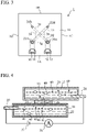
- a particle analysis device 1 As shown in FIG. 1 , a particle analysis device 1 according to an embodiment has a substantially rectangular parallelepiped shape, and the lengths of the four side surfaces 1A, 1B, 1C, and 1D are equal. That is, as shown in the plan view of FIG. 3 , the particle analysis device 1 has a substantially square contour.
- FIG. 2 is a side view of the particle analysis device 1 showing two side surfaces 1A and 1C.
- the particle analysis device 1 has an upper liquid space 20, a lower liquid space 22, and a connection pore 26.
- Each of the liquid spaces 20 and 22 extends linearly in a horizontal direction, in which a liquid 37 is stored in the first liquid space 20 and a liquid 38 is stored in the lower liquid space 22.
- the liquid (first liquid) 37 stored in the upper liquid space 20 and the liquid (second liquid) 38 stored in the lower liquid space 22 are shown by diagonal lines in different directions.
- the lower liquid space 22 is arranged below the upper liquid space 20, and the liquid spaces 20 and 22 are connected to each other by the connection pore 26.
- the liquid spaces 20 and 22 intersect each other at a right angle in plan view.
- the particle analysis device 1 also includes a hole (first hole) 20A, a hole 20B, a hole (second hole) 22A, and a hole 22B.
- Each of the holes 20A, 20B, 20C, and 20d has an opening that opens at the top surface of the particle analysis device 1.
- the hole 20A and the hole 20B extend vertically from the top surface of the particle analysis device 1 to the upper liquid space 20.
- the hole 22A and the hole 22B extend vertically from the top surface of the particle analysis device 1 to the lower liquid space 22.
- the hole 20A, the hole 20B, and the upper liquid space 20 form a reservoir for the liquid 37.
- the hole 22A, the hole 22B, and the lower liquid space 22 form another reservoir for the liquid 38.
- the particle analysis device 1 has a first electrode 28 and a second electrode 30.
- the first electrode 28 is used for applying an electric potential to the liquid 37 in the first liquid space 20 through the hole 20A.
- the second electrode 30 is used for applying an electric potential through the hole 22A to the liquid 38 in the lower liquid space 22.
- the electric potential applied by the second electrode 30 is different from that applied by the first electrode 28.
- the second electrode 30 is an anode and the first electrode 28 is a cathode. Since the liquid spaces 20 and 22 are connected via the connection pore 26, an electric current flows through the liquid 37 and the liquid 38 inside the liquid spaces 20 and 22.
- FIG. 4 schematically illustrates the principle of particle analysis used in the particle analysis device 1.
- the liquid 37 containing particles 40 to be analyzed is stored in the upper liquid space 20.
- a liquid 38 which does not originally contain the particles 40, is stored in the lower liquid space 22.
- the liquid 38 stored in the lower liquid space 22 may contain the particles 40.
- the liquid spaces 20 and 22 are connected to each other via the connection pore 26 that is a through-hole formed in a chip (nanopore chip) 24.
- a DC (direct current) power supply 35 and a current meter 36 are connected to the first electrode 28 and the second electrode 30.
- the DC power supply 35 is, for example, a battery, but is not limited to a battery.
- Electrophoresis caused by the potential difference applied to the electrodes 28 and 30 causes the particles 40 contained in the liquid 37 stored in the lowermost plate 2 to pass the connection pore 26 and to flow into the liquid 38 stored in the lower liquid space 22.
- the current value flowing through the liquid 37 and the liquid 38 changes.
- the change in current value can be observed using the current meter 36.
- characteristics e.g., type, shape, and size
- the particle analysis device 1 can be used to analyze a variety of particles, such as exosomes, pollens, viruses, and bacteria.
- the particle analysis device 1 includes multiple stacked square plates 2, 4, 6, 8, and 10 joined together.
- some or all of these plates are formed from transparent or semi-transparent material, and storage state of the liquid 37 or the liquid 38 in the cavities of the particle analysis device 1 (the hole 20A, the hole 20B, the hole 22A, and the hole 22B, and the liquid spaces 20 and 22) can be observed from outside the particle analysis device 1.
- the storage states of the liquids are observable, and these plates may be opaque.
- the plates 2, 4, 6, 8, and 10 are formed from electrically and chemically inert and insulating materials.
- Each plate may be formed from a rigid material or from an elastic material.
- Preferred rigid materials include resin materials, such as polycarbonate, polyethylene terephthalate, acrylic, cyclic olefin, polypropylene, polystyrene, polyester, and polyvinyl chloride.
- Preferred elastic materials include elastomers, for example, silicone rubber containing PDMS (polydimethylsiloxane) or urethane rubber.
- the plate 2 is formed, for example, from one of the preferred rigid materials described above.
- a horizontal groove 4g is formed in the center of the lower surface of the next plate 4.
- the groove 4g forms the lower liquid space 22.
- a communication hole 4t penetrating the plate 4 in a vertical direction is formed in the center of the groove 4g.
- the communication hole 4t connects the lower liquid space 22 (groove 4g) with the connection pore 26 of the chip 24.
- vertically penetrating cylindrical through-holes 4a and 4d are formed in the plate 4.
- the through-holes 4a and 4d have the same diameter.
- the through-hole 4a communicates with one end of the groove 4g, whereas the through-hole 4d communicates with the other end of the groove 4g.
- the plate 4 may be formed from one of the rigid materials described above, but is preferably formed from one of the elastic materials described above.
- a recess 6h having a rectangular-parallelepiped shape is formed in the center of the lower surface of the next plate 6.
- the recess 6h contains the chip 24 having the connection pore 26.
- the chip 24 is fitted into the recess 6h.
- the chip 24 may be removable or non-removable from the recess 6h.
- a horizontal groove 6g is formed in the center of the upper surface of the plate 6. When the plates 6 and 8 are joined together, the groove 6g forms the upper liquid space 20.
- a vertically penetrating communication hole 6t is formed in the center of the groove 6g.
- the communication hole 6t connects the upper liquid space 20 (the groove 6g) with the connection pore 26 of the chip 24.
- the cross sections of the communication holes 4t and 6t are circular.
- the plate 6 has vertically penetrating cylindrical through-holes 6a and 6d.
- the through-holes 6a and 6d have the same diameter as that of the through-holes 4a and 4d.
- the through-hole 6a communicates with the through-hole 4a of the plate 4 immediately below it, and thus with one end of the groove 4g, whereas the through-hole 6d communicates with the through-hole 4d, and thus with the other end of the groove 4g.
- the plate 6 may be formed from one of the rigid materials described above, but is preferably formed from one of the elastic materials described above.
- the chip (nanopore chip) 24 has a rectangular parallelepiped shape, for example, a square plate shape. In the center of the chip 24, the vertically penetrating connection pore 26 is formed.
- the chip 24 is made from an electrically and chemically inert and insulating material, such as glass, sapphire, a ceramic, a resin, an elastomer, SiO 2 , SiN, or Al 2 O 3 .
- the chip 24 is made from a material harder than the material of the plates 2, 4, 6, 8, and 10, for example, glass, sapphire, ceramics, SiO 2 , SiN, or Al 2 O 3 , but a resin or an elastomer may be used to form the chip 24.
- the user may select an appropriate chip 24 depending on the application of the particle analysis device 1. For example, the user may prepare multiple chips 24 with connection pores 26 having different dimensions or shapes, and may select a chip 24 to be fitted into the recess to change the particles 40 to be analyzed.
- the chip 24 be hydrophilized so that the liquid can easily pass through the connection hole 26 without clogging the connection pore 26.
- the hydrophilization treatment includes, for example, irradiating the chip 24 with oxygen plasma or ultraviolet rays. Ultraviolet rays may be irradiated in the form of a laser beam.
- cylindrical through-holes 8a, 8b, 8c, and 8d penetrating the plate 8 in a vertical direction are formed.
- the through-holes 8a, 8b, 8c, and 8d have the same diameter as that of the through-holes 4a, 4d, 6a and 6d.
- the through-hole 8a communicates with the through-hole 6a of the plate 6 disposed immediately below it, whereas the through-hole 8d communicates with the through-hole 6d.
- the through-hole 8b communicates with one end of the groove 6g of the plate 6, whereas the through-hole 8c communicates with the other end of the groove 6g.
- the electrodes 28 and 30 are arranged in parallel, and the first electrode 28 gives an electric potential to the liquid 37 in the through-hole 8b, whereas the second electrode 30 gives another electric potential to the liquid 38 in the through-hole 8a.
- the plate 8 may be formed from one of the rigid materials described above, but is preferably formed from one of the elastic materials described above.
- the through-holes 10a, 10b, 10c, and 10d are formed in the uppermost plate 10.
- the through-holes 10a and 10b have a diameter that is greater than that of the through-holes 8a, 8b, 8c, and 8d, whereas the through-holes 10c and 10d have a diameter that is equal to that of the through-holes 8a, 8b, 8c, and 8d.
- the through-holes 10a, 10b, 10c, and 10d respectively communicate with the through-holes 8a, 8b, 8c, and 8d of the plate 8 immediately below them.
- a first electrode-rod-insertion hole 32 exposing the first electrode 28 disposed below the plate 10 and a second electrode-rod-insertion hole 34 exposing the second electrode 30 are formed.
- Each of the electrode-rod-insertion holes 32 and 34 has an opening that opens at the top surface of the particle analysis device 1, and penetrates the plate 10 to extend from the top surface to the electrode 28 or 30.
- the plate 10 may be formed from one of the elastic materials described above, but is formed from one of the rigid materials described above.
- An electrode rod is inserted into each of the electrode-rod-insertion holes 32 and 34.
- the electrode rods are brought into contact with the electrodes 28 and 30, respectively, and apply electric potentials to the liquids 37 and 38.
- the aforementioned hole 20A is constituted of the through-holes 10b and 8B and penetrates the plates 10 and 8 to reach one end of the groove 6g in the plate 6, i.e., the upper liquid space 20.
- the through-hole 10b is the opening of the hole 20A that opens at the top surface of the particle analysis device 1.
- the first electrode 28 is provided in the middle of the hole 20A.
- the hole 20B is constituted of the through-holes 10c and 8c and penetrates the plates 10 and 8 to reach the other end of the groove 6g in the plate 6, i.e., the upper liquid space 20.
- the through-hole 10c is the opening of the hole 20B that opens at the top surface of the particle analysis device 1.
- the hole 22A is constituted of the through-holes 10a, 8a, 6a, and 4a and penetrates the plates 10, 8, 6, and 4 to reach one end of the groove 4g in the plate 4, i.e., the lower liquid space 22.
- the through-hole 10a is the opening of the hole 22A that opens at the top surface of the particle analysis device 1.
- the second electrode 30 is provided in the middle of the hole 22A.
- the hole 22B is constituted of the through-holes 10d, 8d, 6d, and 4d and penetrates the plates 10, 8, 6, and 4 to reach the other end of the groove 4g in the plate 4, i.e., the lower liquid space 22.
- the through-hole 10d is the opening of the hole 22B that opens at the top surface of the particle analysis device 1.
- plates 2, 4, 6, 8, and 10 can be bonded together with an adhesive.
- the plates 2, 4, 6, 8, and 10 be compressed in a vertical direction, so that leakage of liquid from the holes 20A, 20B, 22A, and 22B and the liquid spaces 20 and 22 is prevented as far as possible after joining.
- the chip 24 is formed from a brittle material
- at least one of the plates 4 and 6 around the chip 24 is preferably formed from one of the above-described elastic materials in order to prevent the chip 24 from being damaged.
- the plate 6, into which the chip 24 is fitted is preferably formed from one of the above-described elastic materials, and the recess 6h of the plate 6 preferably has dimensions (horizontal dimensions) suitable for the chip 24 to be tightly fitted.
- the depth of the recess 6h is preferably the same as or slightly greater than the height of the chip 24.
- the electrodes 28 and 30 are formed from materials with high electrical conductivity. For example, silver-silver chloride (Ag/AgCI), platinum, or gold can be used to form the electrodes 28 and 30. Alternatively, the electrodes 28 and 30 can be formed from a material containing any or all of these metals and an elastomer.
- Ag/AgCI silver-silver chloride
- platinum platinum
- gold gold
- the electrodes 28 and 30 can be formed from a material containing any or all of these metals and an elastomer.
- each of the electrodes 28 and 30 formed on the plate 8 is a flat sheet and is sandwiched between the two plates 8 and 10. As shown in FIG. 6 , each of the electrodes 28 and 30 has a circular annular portion 42 formed around the through-hole 8b or 8a (a part of the hole 20A or the hole 22A) of the plate 8 and a rectangular extending portion 44 connected to the circular annular portion 42.
- the circular annular portion 42 has a through-hole having a diameter that is the same as those of the through-hole 8a and 8b.
- the circular annular portion 42 is formed substantially concentrically with the through-hole 8a or 8b of the plate 8, and substantially concentrically overlaps with the through-hole 10a or 10b of the plate 10 directly above.
- the width of the extension portion 44 is less than the outer diameter of the circular annular portion 42.
- a first electrode rod 46 is inserted into the first electrode-rod-insertion hole 32 and is brought into contact with the circular annular portion 42 of the first electrode 28, and the second electrode rod 48 is inserted into the second electrode-rod-insertion hole 34 and is brought into contact with the circular annular portion 42 of the second electrode 30.
- the hole 20A has the through-hole 10b, which is disposed above the first electrode 28, and the through-hole 8b, which is disposed below the first electrode 28.
- the through-hole 10b has a greater diameter and thus a greater area than those of the through-hole 8b.
- the outer diameter of the circular annular portion 42 of the first electrode 28 is greater than the diameter of the through-hole 10b disposed immediately above it.
- the hole 22A has the through-hole 10a, which is disposed above the second electrode 30, and the through-hole 8a, which is disposed below the second electrode 30.
- the through-hole 10a has a greater diameter and thus a greater area than those of the through-hole 8a.
- the outer diameter of the circular annular portion 42 of the second electrode 30 is greater than the diameter of the through-hole 10a disposed immediately above it.
- each electrode overlaps the through-hole 10b or 10a having an opening area greater than that of the through-hole 8b or 8a. Therefore, the contact area between the liquid injected into the holes and the electrodes is secured to be large, and the reliability of analysis of the particles can be improved.
- the second electrode 30 is in contact with the liquid 38 inside the hole 22A (through-holes 10A and 8A) with a large contact area
- the first electrode 28 is in contact with the liquid 37 inside the hole 20A (through-holes 10b and 8b) with a large contact area.
- the circular annular portion 42 since the outer diameter of the circular annular portion 42 is greater than that of the through-holes 10b and 10a immediately above the circular annular portion 42, so that even when the position of the circular annular portion 42 deviates slightly from the desired position (i.e., even when the accuracy of the position of the circular annular portion 42 is incorrect), the circular annular portion 42 overlaps the through-hole 10b or 10a with a high degree of reliability. Accordingly, in a plurality of particle analysis devices 1, the contact area of the liquid injected into the holes and the electrodes is uniform, and the reliability of the particle analysis can be improved.
- each of the electrodes 28 and 30 intersects a hole 20A or hole 22A approximately orthogonally.
- Each of the electrodes 28 and 30 is a flat sheet, so that the electrodes 28 and 30 are compressed between the two plates 8 and 10 and are deformed as shown in FIG. 7 . Since the plates 8 and 10 are made from a softer material than the material of the electrodes 28 and 30, the plates 8 and 10 also deform and absorb the thickness of the electrodes 28 and 30 ( FIG. 7 shows the softer plate 8 is more deformed than the plate 10).
- gaps may occur around the electrodes 28 and 30 between the plates 8 and 10.
- the gaps between the plates 8 and 10 allow the liquid in the holes 20A and 22A to leak out.
- FIGS. 8 and 9 show the liquid leaking from holes 20A and 22A in phantom lines.
- the liquid that was in contact with the top surface of the circular annular portion 42 of each electrode may leak out into the gaps between the plates 8 and 10 around the electrodes due to the thickness of the electrodes, as liquid leakage L1.
- the ranges of the liquid leakage L1 correspond to the gaps between the plates 8 and 10 around the electrodes.
- the liquid leakage L1 travels from the side of the circular annular portion 42 of the electrode through both sides of the extending portion 44 to reach the electrode-rod-insertion holes 32 or 34, and can appear in the electrode-rod-insertion holes 32 and 34, as liquid leakage L2.
- the ranges of the liquid leakage L2 are within the electrode-rod-insertion holes 32 and 34 surrounded by the walls of the plates 8 and 10.
- the electrodes 28 and 30 are not interposed between the plates 8 and 10. Accordingly, there is almost no liquid leakage L2 outside the electrode-rod-insertion holes 32 and 34.
- the width of the extending portions 44 of the electrodes 28 and 30 is less than the width of the electrode-rod-insertion holes 32 and 34, and the ends 28E and 30E of the extending portions 44 of the electrodes 28 and 30 are disposed within the ranges of the electrode-rod-insertion holes 32 and 34, so that there is almost no liquid leakage L2 outside the electrode-rod-insertion holes 32 and 34.
- the plate 10 and the plate 8 can be regarded as being liquid-tightly bonded.
- the plate 10 directly above the first electrode 28 and the second electrode 30 is liquid-tightly bonded to the plate 8 directly below the first electrode 28 and the second electrode 30, and around the entirety of the second electrode 30, the plate 10 directly above the first electrode 28 and the second electrode 30 is liquid-tightly bonded to the plate 8 directly below the first electrode 28 and the second electrode 30.
- a region in which the plate 10 is liquid-tightly bonded to the plate 8 is interposed between the first electrode 28 and the second electrode 30.
- the liquid leakage reaches the side surface 1A of the particle analysis device 1, then the liquid is likely to travel through the interference between the plates 10 and 8 at the side surface 1A.
- the first liquid 37 that was stored in the first hole 20A may come into contact with the liquid 38 that was stored in the second hole 22A via the interference between the plates 10 and 8 at the side surface 1A.
- the electrodes 28 and 30, which are sandwiched between the same two plates 10 and 8 and arranged at the same height level, may be short-circuited. If the electrodes 28 and 30 are short-circuited, the current flowing between the electrodes 28 and 30 may become excessive and/or unstable, making it impossible to accurately analyze the particles.
- each of the electrode-rod-insertion holes 32 and 34 extends from the top surface of the particle analysis device 1 to the corresponding electrode 28 or 30 and does not open at any side surface 1A, 1B, 1C, or 1D of the particle analysis device 1, and the first electrode 28 and the second electrode 30 are not exposed at side surfaces 1A, 1B, 1C, and 1D of the particle analysis device 1.
- the electrodes 28 and 30 are located away from any side surface of the particle analysis device 1.
- the electrode 28 terminates within the electrode-rod-insertion hole 32 and is farther from the side surface 1A of the particle analysis device 1 than an end of the first electrode-rod-insertion hole 32 on the side of the side surface 1A of the particle analysis device 1 (an outer end of the hole 32).
- the electrode 30 also terminates within the electrode-rod-insertion hole 34 and is farther from the side surface 1A of the particle analysis device 1 than an end of the first electrode-rod-insertion hole 34 on the side of the side surface 1A of the particle analysis device 1 (an outer end of the hole 34). Accordingly, in a case in which the liquid leaks from the inside of the first hole 20A and flows along the first electrode 28 between the two plates 10 and 8, even if the leaking liquid may enter the first electrode-rod-insertion hole 32 surrounded by walls of the plates 10 and 8, the leaking liquid is unlikely to leak from the side surfaces of the particle analysis device 1.
- the liquid, which leaked from the inside of the first hole 20A, is less likely to cause a short circuit between the first electrode 28 and the second electrode 30.
- the plate 10 directly above the first electrode 28 and the second electrode 30 is liquid-tightly bonded to the plate 8 directly below the first electrode 28 and the second electrode 30, around the entirety of the first electrode 28.
- the plate 10 directly above the first electrode 28 and the second electrode 30 is liquid-tightly bonded to the plate 8 directly below the first electrode 28 and the second electrode 30, around the entirety of the second electrode 30.
- a region in which the plate 10 is liquid-tightly bonded to the plate 8 is interposed between the first electrode 28 and the second electrode 30.
- the liquid is unlikely to reach the second electrode 30, and even if the liquid leaks from the inside of the second hole 22 and flows along second electrode 30 between the two plates, the liquid is unlikely to reach the first electrode 28. Therefore, the risk of the liquid causing a short circuit between the first and second electrodes 28 and 30 is reduced.
- the particle analysis device 1 In a case in which the particle analysis device 1 is stored, it is preferable to place the particle analysis device 1 in a vacuum or underwater environment to protect the above-mentioned hydrophilized chip 24 from the air.
- a vacuum or underwater environment water that has entered the holes 20A and 22A causes the liquid leakage L1 and L2.
- the particle analysis device 1 Even if the particle analysis device 1 is taken out from the water for use and the surfaces of the particle analysis device 1 are wiped with a cloth, it is difficult to remove the liquid leakage L1 and L2 between two plates 10 and 8. In this case, if the liquid leakage is connected between the electrodes 28 and 30, the electrodes 28 and 30 will be short-circuited.
- the electrode-rod-insertion holes 32 and 34 have an approximately semicircular contour.
- the contours of the electrode-rod-insertion holes 32 and 34 are not limited to the shape in the embodiment.
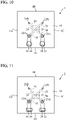
- the electrode-rod-insertion holes 32 and 34 may have a circular contour, as shown in FIG. 10 , or a rectangular contour, as shown in FIG. 11 .
- the width of the electrode-rod-insertion holes 32 and 34 in the embodiment is greater than the width of the extending portions 44 of the electrodes 28 and 30.
- the relative size of the electrode-rod-insertion holes 32 and 34 to the extending portions 44 of the electrodes 28 and 30 is not limited to the embodiment. As shown in FIG. 12 , the width of the electrode-rod-insertion holes 32 and 34 may be less than the width of the extending portions 44 of the electrodes 28 and 30, and the electrode-rod-insertion holes 32 and 34 fall within the ranges of the ends of the extending portions 44.
- the electrodes 28 and 30 terminate within the electrode-rod-insertion holes 32 and 34, respectively, and the ends 28E and 30E of the electrodes 28 and 30 are distant respectively from the inner walls of the electrode-rod-insertion holes 32 and 34 on the side of the side surface 1A.
- the ends 28E and 30E of the electrodes 28 and 30 may be respectively in contact with the inner walls of the electrode-rod-insertion holes 32 and 34 on the side of the side surface 1A. Even in this case, there is almost no liquid leakage L2 outside the electrode-rod-insertion holes 32 and 34.
- the ends 28E and 30E of the electrodes 28 and 30 may extend toward the side surface 1A beyond the inner walls of the electrode-rod-insertion holes 32 and 34 on the side of the side surface 1A, respectively. However, the ends 28E and 30E do not reach the side surface 1A of the particle analysis device 1 and are not exposed at the side surface 1A.
- the plates 10 and 8 are liquid-tightly bonded by means of irradiation of vacuum ultraviolet light or oxygen plasma.
- a compression mechanism e.g., a clamping mechanism, screws, or a pinch
- a pinch e.g., a clamping mechanism, screws, or a pinch
- the number of plates in the particle analysis device is not limited to the above embodiment.
- the upper liquid space 20 is defined by the groove 6g formed in the single plate 6, but the upper liquid space 20 may be defined by multiple plates (e.g., plates 6 and 8).
- the lower liquid space 22 is defined by the groove 4g formed on the single plate 4, but the lower liquid space 22 may be defined by multiple plates (e.g., plates 4 and 2).
- the chip 24 having the connection pore 26 is located inside the single plate 6, but the chip 24 may be disposed inside multiple plates (e.g., plates 6 and 4).
- the extending portions 44 of the electrodes 28 and 30 are rectangular and has a uniform width. However, the extending portions 44 may have wider and narrower portions, or the width of the extending portions 44 may gradually decrease or increase toward the side surface 1A.
Landscapes
- Chemical & Material Sciences (AREA)
- Health & Medical Sciences (AREA)
- Life Sciences & Earth Sciences (AREA)
- Physics & Mathematics (AREA)
- Analytical Chemistry (AREA)
- General Health & Medical Sciences (AREA)
- Engineering & Computer Science (AREA)
- Pathology (AREA)
- General Physics & Mathematics (AREA)
- Immunology (AREA)
- Biochemistry (AREA)
- Molecular Biology (AREA)
- Dispersion Chemistry (AREA)
- Biomedical Technology (AREA)
- Chemical Kinetics & Catalysis (AREA)
- Hematology (AREA)
- Clinical Laboratory Science (AREA)
- Fluid Mechanics (AREA)
- Electrochemistry (AREA)
- Nanotechnology (AREA)
- Spectroscopy & Molecular Physics (AREA)
- Biophysics (AREA)
- Urology & Nephrology (AREA)
- Food Science & Technology (AREA)
- Medicinal Chemistry (AREA)
- Investigating Or Analyzing Materials By The Use Of Electric Means (AREA)
- Investigating Or Analysing Biological Materials (AREA)
Abstract
Description
- The present invention relates particle analysis devices for analyzing particles contained in a liquid.
- A particle analysis device having two spaces has been proposed for analyzing particles, such as exosomes, pollens, viruses, and bacteria (Patent Documents 1-4). This type of particle analysis device has a pore connecting the two spaces, in which a liquid is stored in one space and another liquid containing particles to be analyzed is stored in the other space. These spaces are provided with different electrical potentials for causing electrophoresis, so that particles pass through the pore. As the particles pass through the pore, the current value flowing through the liquid changes. By observing the change in the current value, characteristics (e.g., type, shape, and size) of the particles that passed through the pore can be analyzed. For example, it is possible to determine the number of particles of a certain type contained in the liquid.
-
- Patent Document 1:
JP-A-2014-174022 - Patent Document 2:
JP-A-2017-156168 - Patent Document 3:
WO 2013/13430 A - Patent Document 4:
WO 2013/137209 A - In the use of this type of particle analysis device, it is desired to improve the certainty of particle analysis. In particular, it is desired to prevent a short circuit between two electrodes used to cause electrophoresis and to measure current values.
- Accordingly, the present invention provides a particle analysis device capable of preventing or reducing a short circuit between two electrodes.
- According to an aspect of the present invention, there is provided a particle analysis device including multiple stacked plates joined together; an upper liquid space formed in at least one of the plates and adapted to store a first liquid; a lower liquid space formed in at least one of the plates, disposed below the upper liquid space and adapted to store a second liquid; a connection pore disposed in at least one of the plates and connecting the upper liquid space to the lower liquid space; a first hole having an opening that opens at a top surface of the particle analysis device, the first hole penetrating at least one of the plates and extending from the top surface to the upper liquid space, the first liquid flowing through the first hole; a second hole having an opening that opens at the top surface, the second hole penetrating at least two of the plates and extending from the top surface to the lower liquid space, the second liquid flowing through the second hole; a first electrode that is a sheet pinched between two of the plates and adapted to apply an electric potential to the first liquid in the upper liquid space through the first hole; a second electrode that is a sheet pinched between the two of the plates, between which the first electrode is pinched, and adapted to apply an electric potential to the second liquid in the lower liquid space through the second hole; a first electrode-rod-insertion hole having an opening that opens at the top surface, the first electrode-rod-insertion hole penetrating at least one of the plates and extending from the top surface to the first electrode; and a second electrode-rod-insertion hole having an opening that opens at the top surface, the second electrode-rod-insertion hole penetrating at least one of the plates and extending from the top surface to the second electrode. The first electrode and the second electrode are configured not to be exposed at a side surface of the particle analysis device.
- In this aspect, the first electrode, which applies an electric potential to the first liquid, and the second electrode, which applies an electric potential to the second liquid, are pinched between the same two plates and are arranged at the same height level. A first electrode is inserted into the first electrode-rod-insertion hole and is brought into contact with the first electrode, and second electrode is inserted into the second electrode-rod-insertion hole and is brought into contact with the second electrode. Each of the first electrode-rod-insertion hole and the second electrode-rod-insertion hole extends from the top surface of the particle analysis device to the corresponding electrode and does not open at any side surface of the particle analysis device, and the first electrode and the second electrode are not exposed at any side surface of the particle analysis device. Accordingly, in a case in which the liquid leaks from the inside of the first hole and flows along the first electrode between the two plates, even if the leaking liquid may enter the first electrode-rod-insertion hole surrounded by walls of the plates, the leaking liquid is unlikely to leak from side surfaces of the particle analysis device. Therefore, if the distance between the first electrode and the second electrode is sufficiently large and the distance between the first electrode-rod-insertion hole and the second-electrode-rod insertion hole is sufficiently large, the liquid, which leaked from the inside of the first hole, is less likely to cause a short circuit between the first electrode and the second electrode.
- On the other hand, in a case in which the liquid leaks from the inside of the second hole and flows along the second electrode between the two plates, even if the leaking liquid may enter the second electrode-rod-insertion hole surrounded by walls of the plates, the leaking liquid is unlikely to leak from side surfaces of the particle analysis device. Therefore, if the distance between the first electrode and the second electrode is sufficiently large and the distance between the first electrode-rod-insertion hole and the second-electrode-rod insertion hole is sufficiently large, the liquid, which leaked from the inside of the first hole, is less likely to cause a short circuit between the first electrode and the second electrode.
- Thus, according to the aspect, it is possible to improve the certainty of particle analysis.
-
-
FIG. 1 is a perspective view showing a particle analysis device according to an embodiment of the present invention; -
FIG. 2 is a side view of the particle analysis device shown inFIG. 1 ; -
FIG. 3 is a plan view of the particle analysis device ofFIG. 1 ; -
FIG. 4 is a conceptual diagram showing the principle of particle analysis used in the particle analysis device ofFIG. 1 ; -
FIG. 5 is an exploded view of the particle analysis device shown inFIG. 1 seen from diagonally above; -
FIG. 6 is an enlarged plan view of the particle analysis device ofFIG. 1 ; -
FIG. 7 is a cross-sectional view taken along line VII-VII inFIG. 6 ; -
FIG. 8 is an enlarged plan view, which is similar toFIG. 3 , of the particle analysis device, showing liquids that leak from holes for storing the liquids; -
FIG. 9 is an enlarged perspective view of the particle analysis device, showing liquids that leak from holes for storing the liquids; -
FIG. 10 is a plan view of a particle analysis device according to a modification of the embodiment of the present invention; -
FIG. 11 is a plan view of a particle analysis device according to another modification of the embodiment of the present invention; -
FIG. 12 is a plan view of a particle analysis device according to another modification of the embodiment of the present invention; -
FIG. 13 is an enlarged plan view of a particle analysis device according to another modification of the embodiment of the present invention; and -
FIG. 14 is an enlarged plan view of a particle analysis device according to another modification of the embodiment of the present invention. - Hereinafter, with reference to the accompanying drawings, various embodiments according to the present invention will be described. It is of note that the drawings are not necessarily to scale, and certain features may be exaggerated or omitted.
- As shown in
FIG. 1 , aparticle analysis device 1 according to an embodiment has a substantially rectangular parallelepiped shape, and the lengths of the fourside surfaces FIG. 3 , theparticle analysis device 1 has a substantially square contour.FIG. 2 is a side view of theparticle analysis device 1 showing twoside surfaces - As shown in
FIGS. 1, 2 , and3 , theparticle analysis device 1 has an upperliquid space 20, a lowerliquid space 22, and aconnection pore 26. Each of theliquid spaces liquid 37 is stored in the firstliquid space 20 and aliquid 38 is stored in the lowerliquid space 22. InFIG. 2 , the liquid (first liquid) 37 stored in the upperliquid space 20 and the liquid (second liquid) 38 stored in the lowerliquid space 22 are shown by diagonal lines in different directions. The lowerliquid space 22 is arranged below the upperliquid space 20, and theliquid spaces connection pore 26. As shown inFIG. 3 , theliquid spaces - The
particle analysis device 1 also includes a hole (first hole) 20A, ahole 20B, a hole (second hole) 22A, and ahole 22B. Each of theholes particle analysis device 1. - The
hole 20A and thehole 20B extend vertically from the top surface of theparticle analysis device 1 to the upperliquid space 20. Thehole 22A and thehole 22B extend vertically from the top surface of theparticle analysis device 1 to the lowerliquid space 22. Thehole 20A, thehole 20B, and the upperliquid space 20 form a reservoir for theliquid 37. Thehole 22A, thehole 22B, and the lowerliquid space 22 form another reservoir for theliquid 38. - Furthermore, the
particle analysis device 1 has afirst electrode 28 and asecond electrode 30. Thefirst electrode 28 is used for applying an electric potential to theliquid 37 in the firstliquid space 20 through thehole 20A. Thesecond electrode 30 is used for applying an electric potential through thehole 22A to theliquid 38 in the lowerliquid space 22. The electric potential applied by thesecond electrode 30 is different from that applied by thefirst electrode 28. For example, thesecond electrode 30 is an anode and thefirst electrode 28 is a cathode. Since theliquid spaces connection pore 26, an electric current flows through the liquid 37 and the liquid 38 inside theliquid spaces -
FIG. 4 schematically illustrates the principle of particle analysis used in theparticle analysis device 1. In theupper liquid space 20, the liquid 37 containingparticles 40 to be analyzed is stored. In thelower liquid space 22, a liquid 38, which does not originally contain theparticles 40, is stored. However, the liquid 38 stored in thelower liquid space 22 may contain theparticles 40. Theliquid spaces connection pore 26 that is a through-hole formed in a chip (nanopore chip) 24. A DC (direct current)power supply 35 and acurrent meter 36 are connected to thefirst electrode 28 and thesecond electrode 30. TheDC power supply 35 is, for example, a battery, but is not limited to a battery. - Electrophoresis caused by the potential difference applied to the
electrodes particles 40 contained in the liquid 37 stored in thelowermost plate 2 to pass theconnection pore 26 and to flow into the liquid 38 stored in thelower liquid space 22. When theparticles 40 pass through theconnection pore 26, the current value flowing through the liquid 37 and the liquid 38 changes. The change in current value can be observed using thecurrent meter 36. By observing the change in the current value, characteristics (e.g., type, shape, and size) of theparticles 40 that passed through theconnection pore 26 can be analyzed. For example, it is possible to determine the number ofparticles 40 of a certain type contained in the liquid 37. Theparticle analysis device 1 can be used to analyze a variety of particles, such as exosomes, pollens, viruses, and bacteria. - As shown in
FIGS. 1, 2 , and3 , theparticle analysis device 1 includes multiple stackedsquare plates hole 20A, thehole 20B, thehole 22A, and thehole 22B, and theliquid spaces 20 and 22) can be observed from outside theparticle analysis device 1. However, it is not absolutely necessary that the storage states of the liquids are observable, and these plates may be opaque. - The
plates - As shown in
FIGS. 2 and5 , neither grooves nor holes are formed in thelowermost plate 2. Theplate 2 is formed, for example, from one of the preferred rigid materials described above. - A
horizontal groove 4g is formed in the center of the lower surface of thenext plate 4. When theplates groove 4g forms thelower liquid space 22. In the center of thegroove 4g, acommunication hole 4t penetrating theplate 4 in a vertical direction is formed. Thecommunication hole 4t connects the lower liquid space 22 (groove 4g) with theconnection pore 26 of thechip 24. In addition, vertically penetrating cylindrical through-holes plate 4. The through-holes hole 4a communicates with one end of thegroove 4g, whereas the through-hole 4d communicates with the other end of thegroove 4g. Theplate 4 may be formed from one of the rigid materials described above, but is preferably formed from one of the elastic materials described above. - A
recess 6h having a rectangular-parallelepiped shape is formed in the center of the lower surface of thenext plate 6. Therecess 6h contains thechip 24 having theconnection pore 26. Thechip 24 is fitted into therecess 6h. Thechip 24 may be removable or non-removable from therecess 6h. Ahorizontal groove 6g is formed in the center of the upper surface of theplate 6. When theplates groove 6g forms theupper liquid space 20. In the center of thegroove 6g, a vertically penetratingcommunication hole 6t is formed. Thecommunication hole 6t connects the upper liquid space 20 (thegroove 6g) with theconnection pore 26 of thechip 24. The cross sections of thecommunication holes - The
plate 6 has vertically penetrating cylindrical through-holes holes holes hole 6a communicates with the through-hole 4a of theplate 4 immediately below it, and thus with one end of thegroove 4g, whereas the through-hole 6d communicates with the through-hole 4d, and thus with the other end of thegroove 4g. Theplate 6 may be formed from one of the rigid materials described above, but is preferably formed from one of the elastic materials described above. - The chip (nanopore chip) 24 has a rectangular parallelepiped shape, for example, a square plate shape. In the center of the
chip 24, the vertically penetratingconnection pore 26 is formed. Thechip 24 is made from an electrically and chemically inert and insulating material, such as glass, sapphire, a ceramic, a resin, an elastomer, SiO2, SiN, or Al2O3. Preferably, thechip 24 is made from a material harder than the material of theplates chip 24. The user may select anappropriate chip 24 depending on the application of theparticle analysis device 1. For example, the user may preparemultiple chips 24 withconnection pores 26 having different dimensions or shapes, and may select achip 24 to be fitted into the recess to change theparticles 40 to be analyzed. - It is preferable that the
chip 24 be hydrophilized so that the liquid can easily pass through theconnection hole 26 without clogging theconnection pore 26. The hydrophilization treatment includes, for example, irradiating thechip 24 with oxygen plasma or ultraviolet rays. Ultraviolet rays may be irradiated in the form of a laser beam. - In the
next plate 8, cylindrical through-holes plate 8 in a vertical direction are formed. The through-holes holes hole 8a communicates with the through-hole 6a of theplate 6 disposed immediately below it, whereas the through-hole 8d communicates with the through-hole 6d. The through-hole 8b communicates with one end of thegroove 6g of theplate 6, whereas the through-hole 8c communicates with the other end of thegroove 6g. On the upper surface of theplate 8, theelectrodes first electrode 28 gives an electric potential to the liquid 37 in the through-hole 8b, whereas thesecond electrode 30 gives another electric potential to the liquid 38 in the through-hole 8a. Theplate 8 may be formed from one of the rigid materials described above, but is preferably formed from one of the elastic materials described above. - In the
uppermost plate 10, vertically penetrating through-holes holes holes holes holes holes holes plate 8 immediately below them. - In addition, in the
uppermost plate 10, a first electrode-rod-insertion hole 32 exposing thefirst electrode 28 disposed below theplate 10 and a second electrode-rod-insertion hole 34 exposing thesecond electrode 30 are formed. Each of the electrode-rod-insertion holes particle analysis device 1, and penetrates theplate 10 to extend from the top surface to theelectrode plate 10 may be formed from one of the elastic materials described above, but is formed from one of the rigid materials described above. - An electrode rod is inserted into each of the electrode-rod-
insertion holes electrodes liquids - The
aforementioned hole 20A is constituted of the through-holes 10b and 8B and penetrates theplates groove 6g in theplate 6, i.e., theupper liquid space 20. The through-hole 10b is the opening of thehole 20A that opens at the top surface of theparticle analysis device 1. In the middle of thehole 20A, thefirst electrode 28 is provided. Thehole 20B is constituted of the through-holes plates groove 6g in theplate 6, i.e., theupper liquid space 20. The through-hole 10c is the opening of thehole 20B that opens at the top surface of theparticle analysis device 1. - The
hole 22A is constituted of the through-holes plates groove 4g in theplate 4, i.e., thelower liquid space 22. The through-hole 10a is the opening of thehole 22A that opens at the top surface of theparticle analysis device 1. Thesecond electrode 30 is provided in the middle of thehole 22A. Thehole 22B is constituted of the through-holes plates groove 4g in theplate 4, i.e., thelower liquid space 22. The through-hole 10d is the opening of thehole 22B that opens at the top surface of theparticle analysis device 1. - These
plates liquid spaces plates plates plates holes liquid spaces - When the
chip 24 is formed from a brittle material, at least one of theplates chip 24 is preferably formed from one of the above-described elastic materials in order to prevent thechip 24 from being damaged. In addition, in order to prevent leakage of liquid in theconnection pore 26 of thechip 24, theplate 6, into which thechip 24 is fitted, is preferably formed from one of the above-described elastic materials, and therecess 6h of theplate 6 preferably has dimensions (horizontal dimensions) suitable for thechip 24 to be tightly fitted. Furthermore, in order to prevent a gap from occurring between the lower surface of thechip 24 and the upper surface of theplate 4, the depth of therecess 6h is preferably the same as or slightly greater than the height of thechip 24. - The
electrodes electrodes electrodes - Each of the
electrodes plate 8 is a flat sheet and is sandwiched between the twoplates FIG. 6 , each of theelectrodes annular portion 42 formed around the through-hole hole 20A or thehole 22A) of theplate 8 and a rectangular extendingportion 44 connected to the circularannular portion 42. - The circular
annular portion 42 has a through-hole having a diameter that is the same as those of the through-hole annular portion 42 is formed substantially concentrically with the through-hole plate 8, and substantially concentrically overlaps with the through-hole plate 10 directly above. - An end of the extending
portion 44 on the opposite side of the circularannular portion 42 overlaps the electrode-rod-insertion hole plate 10 directly above. The width of theextension portion 44 is less than the outer diameter of the circularannular portion 42. Afirst electrode rod 46 is inserted into the first electrode-rod-insertion hole 32 and is brought into contact with the circularannular portion 42 of thefirst electrode 28, and thesecond electrode rod 48 is inserted into the second electrode-rod-insertion hole 34 and is brought into contact with the circularannular portion 42 of thesecond electrode 30. - The
hole 20A has the through-hole 10b, which is disposed above thefirst electrode 28, and the through-hole 8b, which is disposed below thefirst electrode 28. The through-hole 10b has a greater diameter and thus a greater area than those of the through-hole 8b. The outer diameter of the circularannular portion 42 of thefirst electrode 28 is greater than the diameter of the through-hole 10b disposed immediately above it. - The
hole 22A has the through-hole 10a, which is disposed above thesecond electrode 30, and the through-hole 8a, which is disposed below thesecond electrode 30. The through-hole 10a has a greater diameter and thus a greater area than those of the through-hole 8a. The outer diameter of the circularannular portion 42 of thesecond electrode 30 is greater than the diameter of the through-hole 10a disposed immediately above it. - Thus, the circular
annular portion 42 of each electrode overlaps the through-hole hole FIG. 7 , thesecond electrode 30 is in contact with the liquid 38 inside thehole 22A (through-holes 10A and 8A) with a large contact area, and thefirst electrode 28 is in contact with the liquid 37 inside thehole 20A (through-holes - In addition, since the outer diameter of the circular
annular portion 42 is greater than that of the through-holes annular portion 42, so that even when the position of the circularannular portion 42 deviates slightly from the desired position (i.e., even when the accuracy of the position of the circularannular portion 42 is incorrect), the circularannular portion 42 overlaps the through-hole particle analysis devices 1, the contact area of the liquid injected into the holes and the electrodes is uniform, and the reliability of the particle analysis can be improved. - As shown in
FIG. 7 , each of theelectrodes hole 20A orhole 22A approximately orthogonally. Each of theelectrodes electrodes plates FIG. 7 . Since theplates electrodes plates electrodes 28 and 30 (FIG. 7 shows thesofter plate 8 is more deformed than the plate 10). - However, due to the thickness of the
electrodes electrodes plates plates holes -
FIGS. 8 and 9 show the liquid leaking fromholes annular portion 42 of each electrode may leak out into the gaps between theplates plates - The liquid leakage L1 travels from the side of the circular
annular portion 42 of the electrode through both sides of the extendingportion 44 to reach the electrode-rod-insertion holes insertion holes insertion holes plates insertion holes electrodes plates insertion holes portions 44 of theelectrodes insertion holes ends portions 44 of theelectrodes insertion holes insertion holes - In the areas in which there is no liquid leakage L1 or L2, the
plate 10 and theplate 8 can be regarded as being liquid-tightly bonded. In other words, around the entirety of thefirst electrode 28, theplate 10 directly above thefirst electrode 28 and thesecond electrode 30 is liquid-tightly bonded to theplate 8 directly below thefirst electrode 28 and thesecond electrode 30, and around the entirety of thesecond electrode 30, theplate 10 directly above thefirst electrode 28 and thesecond electrode 30 is liquid-tightly bonded to theplate 8 directly below thefirst electrode 28 and thesecond electrode 30. In addition, a region in which theplate 10 is liquid-tightly bonded to theplate 8 is interposed between thefirst electrode 28 and thesecond electrode 30. - If the liquid leakage reaches the
side surface 1A of theparticle analysis device 1, then the liquid is likely to travel through the interference between theplates side surface 1A. In this case, the first liquid 37 that was stored in thefirst hole 20A may come into contact with the liquid 38 that was stored in thesecond hole 22A via the interference between theplates side surface 1A. In other words, theelectrodes plates electrodes electrodes - However, each of the electrode-rod-
insertion holes particle analysis device 1 to the correspondingelectrode side surface particle analysis device 1, and thefirst electrode 28 and thesecond electrode 30 are not exposed at side surfaces 1A, 1B, 1C, and 1D of theparticle analysis device 1. In addition, theelectrodes particle analysis device 1. Theelectrode 28 terminates within the electrode-rod-insertion hole 32 and is farther from theside surface 1A of theparticle analysis device 1 than an end of the first electrode-rod-insertion hole 32 on the side of theside surface 1A of the particle analysis device 1 (an outer end of the hole 32). Theelectrode 30 also terminates within the electrode-rod-insertion hole 34 and is farther from theside surface 1A of theparticle analysis device 1 than an end of the first electrode-rod-insertion hole 34 on the side of theside surface 1A of the particle analysis device 1 (an outer end of the hole 34). Accordingly, in a case in which the liquid leaks from the inside of thefirst hole 20A and flows along thefirst electrode 28 between the twoplates insertion hole 32 surrounded by walls of theplates particle analysis device 1. Therefore, if the distance between thefirst electrode 28 and thesecond electrode 30 is sufficiently large and the distance between the first electrode-rod-insertion hole 32 and the second-electrode-rod insertion hole 34 is sufficiently large, the liquid, which leaked from the inside of thefirst hole 20A, is less likely to cause a short circuit between thefirst electrode 28 and thesecond electrode 30. - On the other hand, in a case in which the liquid leaks from the inside of the second hole 22Aand flows along the
second electrode 30 between the twoplates insertion hole 34 surrounded by walls of theplates particle analysis device 1. Therefore, if the distance between thefirst electrode 28 and thesecond electrode 30 is sufficiently large and the distance between the first electrode-rod-insertion hole 32 and the second-electrode-rod insertion hole 34 is sufficiently large, the liquid, which leaked from the inside of thesecond hole 22A, is less likely to cause a short circuit between thefirst electrode 28 and thesecond electrode 30. - Thus, according to the
particle analysis device 1, it is possible to improve the certainty of particle analysis. - Furthermore, in a region away from the
first electrode 28, theplate 10 directly above thefirst electrode 28 and thesecond electrode 30 is liquid-tightly bonded to theplate 8 directly below thefirst electrode 28 and thesecond electrode 30, around the entirety of thefirst electrode 28. In a region away from thesecond electrode 30, theplate 10 directly above thefirst electrode 28 and thesecond electrode 30 is liquid-tightly bonded to theplate 8 directly below thefirst electrode 28 and thesecond electrode 30, around the entirety of thesecond electrode 30. In addition, a region in which theplate 10 is liquid-tightly bonded to theplate 8 is interposed between thefirst electrode 28 and thesecond electrode 30. Accordingly, even if the liquid leaks from the inside of thefirst hole 20A and flows along thefirst electrode 28 between the two plates, the liquid is unlikely to reach thesecond electrode 30, and even if the liquid leaks from the inside of thesecond hole 22 and flows alongsecond electrode 30 between the two plates, the liquid is unlikely to reach thefirst electrode 28. Therefore, the risk of the liquid causing a short circuit between the first andsecond electrodes - In a case in which the
particle analysis device 1 is stored, it is preferable to place theparticle analysis device 1 in a vacuum or underwater environment to protect the above-mentionedhydrophilized chip 24 from the air. However, in a case in which theparticle analysis device 1 is stored in an underwater environment, water that has entered theholes particle analysis device 1 is taken out from the water for use and the surfaces of theparticle analysis device 1 are wiped with a cloth, it is difficult to remove the liquid leakage L1 and L2 between twoplates electrodes electrodes - In this embodiment, however, the risk of a short circuit between the
electrodes particle analysis device 1, it is possible to improve the certainty of particle analysis. - In this embodiment, the electrode-rod-
insertion holes insertion holes insertion holes FIG. 10 , or a rectangular contour, as shown inFIG. 11 . - Furthermore, the width of the electrode-rod-
insertion holes portions 44 of theelectrodes insertion holes portions 44 of theelectrodes FIG. 12 , the width of the electrode-rod-insertion holes portions 44 of theelectrodes insertion holes portions 44. In this case, even if liquid leakage occurs in the gaps between theplates electrodes first electrode 28 and thesecond electrode 30 if the distance between thefirst electrode 28 and thesecond electrode 30 is sufficiently large and the distance between the first electrode-rod-insertion hole 32 and the second-electrode-rod insertion hole 34 is sufficiently large - Furthermore, in the embodiment, as shown in
Fig. 8 , theelectrodes insertion holes ends electrodes insertion holes side surface 1A. However, as shown inFIG. 13 , theends electrodes insertion holes side surface 1A. Even in this case, there is almost no liquid leakage L2 outside the electrode-rod-insertion holes - In addition, as shown in
Fig. 14 , theends electrodes side surface 1A beyond the inner walls of the electrode-rod-insertion holes side surface 1A, respectively. However, theends side surface 1A of theparticle analysis device 1 and are not exposed at theside surface 1A. As described above, theplates insertion holes side surface 1A if there is a sufficiently large distance between theside surface 1A and theends electrodes - The present invention has been illustrated and described with reference to a preferred embodiment of the present invention. However, it will be understood that a person skilled in the art can change the form and details without departing from the scope of the invention described in the claims. It is intended that such changes, modifications, and alterations should fall within the scope of the present invention.
- For example, a compression mechanism (e.g., a clamping mechanism, screws, or a pinch) that constantly compresses the particle analysis device in a vertical direction may be used to improve sealing between the plates of the particle analysis device.
- The number of plates in the particle analysis device is not limited to the above embodiment. In the embodiment, the
upper liquid space 20 is defined by thegroove 6g formed in thesingle plate 6, but theupper liquid space 20 may be defined by multiple plates (e.g.,plates 6 and 8). In the embodiment, thelower liquid space 22 is defined by thegroove 4g formed on thesingle plate 4, but thelower liquid space 22 may be defined by multiple plates (e.g.,plates 4 and 2). In the embodiment, thechip 24 having theconnection pore 26 is located inside thesingle plate 6, but thechip 24 may be disposed inside multiple plates (e.g.,plates 6 and 4). - In the embodiment, the extending
portions 44 of theelectrodes portions 44 may have wider and narrower portions, or the width of the extendingportions 44 may gradually decrease or increase toward theside surface 1A. - Aspects of the present invention are also set out in the following numbered clauses:
-
Clause 1. A particle analysis device including:- multiple stacked plates joined together;
- an upper liquid space formed in at least one of the plates and adapted to store a first liquid;
- a lower liquid space formed in at least one of the plates, disposed below the upper liquid space and adapted to store a second liquid;
- a connection pore disposed in at least one of the plates and connecting the upper liquid space to the lower liquid space;
- a first hole having an opening that opens at a top surface of the particle analysis device, the first hole penetrating at least one of the plates and extending from the top surface to the upper liquid space, the first liquid flowing through the first hole;
- a second hole having an opening that opens at the top surface, the second hole penetrating at least two of the plates and extending from the top surface to the lower liquid space, the second liquid flowing through the second hole;
- a first electrode that is a sheet pinched between two of the plates and adapted to apply an electric potential to the first liquid in the upper liquid space through the first hole;
- a second electrode that is a sheet pinched between the two of the plates, between which the first electrode is pinched, and adapted to apply an electric potential to the second liquid in the lower liquid space through the second hole;
- a first electrode-rod-insertion hole having an opening that opens at the top surface, the first electrode-rod-insertion hole penetrating at least one of the plates and extending from the top surface to the first electrode; and
- a second electrode-rod-insertion hole having an opening that opens at the top surface, the second electrode-rod-insertion hole penetrating at least one of the plates and extending from the top surface to the second electrode,
- the first electrode and the second electrode being configured not to be exposed at a side surface of the particle analysis device.
-
Clause 2. The particle analysis device according toclause 1, wherein the first electrode and the second electrode are located away from a side surface of the particle analysis device. - Clause 3. The particle analysis device according to
clause -
Clause 4. The particle analysis device according to clause 3, wherein the first electrode-rod-insertion hole has an inner wall on a side of the side surface, wherein the first electrode has an end that is distant from the inner wall of the first electrode-rod-insertion hole, wherein the second electrode-rod-insertion hole has an inner wall on the side of the side surface, and wherein the second electrode has an end that is distant from the inner wall of the second electrode-rod-insertion hole. - Clause 5. The particle analysis device according to clause 3, wherein the first electrode-rod-insertion hole has an inner wall on a side of the side surface, wherein the first electrode has an end that is in contact with the inner wall of the first electrode-rod-insertion hole, wherein the second electrode-rod-insertion hole has an inner wall on the side of the side surface, and wherein the second electrode has an end that is in contact with the inner wall of the second electrode-rod-insertion hole.
-
Clause 6. The particle analysis device according toclause -
Clause 4. The particle analysis device according to any one ofclauses 1 to 6, wherein a plate directly above the first electrode and the second electrode is liquid-tightly bonded to a plate directly below the first electrode and the second electrode around the entirety of the first electrode, wherein the plate directly above the first electrode and the second electrode is liquid-tightly bonded to the plate directly below the first electrode and the second electrode around the entirety of the second electrode, and wherein a region in which the plate directly above the first electrode and the second electrode is liquid-tightly bonded to the plate directly below the first electrode and the second electrode is interposed between the first electrode and the second electrode. - According to this clause, even if the liquid leaks from the inside of the first hole and flows along the first electrode between the two plates, the liquid is unlikely to reach the second electrode, and even if the liquid leaks from the inside of the second hole and flows along second electrode between the two plates, the liquid is unlikely to reach the first electrode. Therefore, the risk of the liquid causing a short circuit between the first and second electrodes is reduced.
-
- 1: Particle analysis device
- 1A, 1B, 1C, 1D: Side surface
- 2, 4, 6, 8, 10: Plate
- 20: Upper liquid space
- 22: Lower liquid space
- 24: Chip (nanopore chip)
- 26: Connection pore
- 37: Liquid (first liquid)
- 38: Liquid (second liquid)
- 20A: Hole (first hole)
- 20B: Hole
- 22A: Hole (second hole)
- 22B: Hole
- 28: First electrode
- 30: Second electrode
- 32: First electrode-rod-insertion hole
- 34: Second electrode-rod-insertion hole
- 46: First electrode rod
- 48: Second electrode rod
- L1: Liquid leakage
- L2: Liquid leakage
Claims (7)
- A particle analysis device comprising:multiple stacked plates joined together;an upper liquid space formed in at least one of the plates and adapted to store a first liquid;a lower liquid space formed in at least one of the plates, disposed below the upper liquid space and adapted to store a second liquid;a connection pore disposed in at least one of the plates and connecting the upper liquid space to the lower liquid space;a first hole having an opening that opens at a top surface of the particle analysis device, the first hole penetrating at least one of the plates and extending from the top surface to the upper liquid space, the first liquid flowing through the first hole;a second hole having an opening that opens at the top surface, the second hole penetrating at least two of the plates and extending from the top surface to the lower liquid space, the second liquid flowing through the second hole;a first electrode that is a sheet pinched between two of the plates and adapted to apply an electric potential to the first liquid in the upper liquid space through the first hole;a second electrode that is a sheet pinched between the two of the plates, between which the first electrode is pinched, and adapted to apply an electric potential to the second liquid in the lower liquid space through the second hole;a first electrode-rod-insertion hole having an opening that opens at the top surface, the first electrode-rod-insertion hole penetrating at least one of the plates and extending from the top surface to the first electrode; anda second electrode-rod-insertion hole having an opening that opens at the top surface, the second electrode-rod-insertion hole penetrating at least one of the plates and extending from the top surface to the second electrode,the first electrode and the second electrode being configured not to be exposed at a side surface of the particle analysis device.
- The particle analysis device according to claim 1, wherein the first electrode and the second electrode are located away from a side surface of the particle analysis device.
- The particle analysis device according to claim 1 or 2, wherein the first electrode terminates within the first electrode-rod-insertion hole and is farther from a side surface of the particle analysis device than an outer end of the first electrode-rod-insertion hole, and wherein the second electrode terminates within the second electrode-rod-insertion hole and is farther from the side surface of the particle analysis device than an outer end of the second electrode-rod-insertion hole.
- The particle analysis device according to claim 3, wherein the first electrode-rod-insertion hole has an inner wall on a side of the side surface, wherein the first electrode has an end that is distant from the inner wall of the first electrode-rod-insertion hole, wherein the second electrode-rod-insertion hole has an inner wall on the side of the side surface, and wherein the second electrode has an end that is distant from the inner wall of the second electrode-rod-insertion hole.
- The particle analysis device according to claim 3, wherein the first electrode-rod-insertion hole has an inner wall on a side of the side surface, wherein the first electrode has an end that is in contact with the inner wall of the first electrode-rod-insertion hole, wherein the second electrode-rod-insertion hole has an inner wall on the side of the side surface, and wherein the second electrode has an end that is in contact with the inner wall of the second electrode-rod-insertion hole.
- The particle analysis device according to claim 1 or 2, wherein the first electrode-rod-insertion hole has an inner wall on a side of the side surface, wherein the first electrode has an end that extends toward the side surface beyond the inner wall of the first electrode-rod-insertion hole, wherein the second electrode-rod-insertion hole has an inner wall on the side of the side surface, and wherein the second electrode has an end that extends toward the side surface beyond the inner wall of the second electrode-rod-insertion hole.
- The particle analysis device according to any one of claims 1 to 6, wherein a plate directly above the first electrode and the second electrode is liquid-tightly bonded to a plate directly below the first electrode and the second electrode around the entirety of the first electrode, wherein the plate directly above the first electrode and the second electrode is liquid-tightly bonded to the plate directly below the first electrode and the second electrode around the entirety of the second electrode, and wherein a region in which the plate directly above the first electrode and the second electrode is liquid-tightly bonded to the plate directly below the first electrode and the second electrode is interposed between the first electrode and the second electrode.
Applications Claiming Priority (2)
| Application Number | Priority Date | Filing Date | Title |
|---|---|---|---|
| JP2020026876 | 2020-02-20 | ||
| PCT/JP2021/003674 WO2021166629A1 (en) | 2020-02-20 | 2021-02-02 | Particle analysis device |
Publications (1)
| Publication Number | Publication Date |
|---|---|
| EP4109074A1 true EP4109074A1 (en) | 2022-12-28 |
Family
ID=77391359
Family Applications (1)
| Application Number | Title | Priority Date | Filing Date |
|---|---|---|---|
| EP21756875.7A Withdrawn EP4109074A1 (en) | 2020-02-20 | 2021-02-02 | Particle analysis device |
Country Status (5)
| Country | Link |
|---|---|
| US (1) | US20230074523A1 (en) |
| EP (1) | EP4109074A1 (en) |
| JP (1) | JPWO2021166629A1 (en) |
| CN (1) | CN115151809A (en) |
| WO (1) | WO2021166629A1 (en) |
Family Cites Families (13)
| Publication number | Priority date | Publication date | Assignee | Title |
|---|---|---|---|---|
| US7238269B2 (en) * | 2003-07-01 | 2007-07-03 | 3M Innovative Properties Company | Sample processing device with unvented channel |
| DE10336849A1 (en) * | 2003-08-11 | 2005-03-10 | Thinxxs Gmbh | flow cell |
| JP4787786B2 (en) * | 2007-04-23 | 2011-10-05 | 三井化学株式会社 | Gas generating apparatus and gas generating method |
| US9494553B2 (en) * | 2007-04-27 | 2016-11-15 | National Institute Of Advanced Industrial Science And Technology | Electrophoresis chip, electrophoresis apparatus, and method for analyzing sample by capillary electrophoresis |
| JP5797926B2 (en) * | 2011-04-21 | 2015-10-21 | 株式会社エンプラス | Fluid handling apparatus, manufacturing method thereof, and fluid handling system |
| CN102280088A (en) | 2011-07-26 | 2011-12-14 | 深圳市华星光电技术有限公司 | Light-emitting diode (LED) dimming method and LED dimming system |
| WO2013136430A1 (en) | 2012-03-13 | 2013-09-19 | 株式会社 東芝 | Single particle analyzer and analysis method |
| JP5904958B2 (en) * | 2013-03-07 | 2016-04-20 | 株式会社東芝 | Semiconductor micro-analysis chip and manufacturing method thereof |
| JP6120437B2 (en) | 2013-03-08 | 2017-04-26 | 国立大学法人大阪大学 | Substance identification method |
| JP2014205115A (en) * | 2013-04-12 | 2014-10-30 | ソニー株式会社 | Method of producing channel device and channel device |
| JP6258144B2 (en) * | 2014-07-18 | 2018-01-10 | 株式会社東芝 | Semiconductor micro analysis chip |
| US11333626B2 (en) * | 2016-02-22 | 2022-05-17 | Hitachi, Ltd. | Biological sample analysis chip, biological sample analyzer and biological sample analysis method |
| JP6762494B2 (en) | 2016-02-29 | 2020-09-30 | 国立大学法人大阪大学 | Exosome shape distribution analyzer, cancer screening device, exosome shape distribution analysis method, and cancer screening method |
-
2021
- 2021-02-02 WO PCT/JP2021/003674 patent/WO2021166629A1/en not_active Ceased
- 2021-02-02 US US17/798,187 patent/US20230074523A1/en not_active Abandoned
- 2021-02-02 CN CN202180014955.0A patent/CN115151809A/en not_active Withdrawn
- 2021-02-02 EP EP21756875.7A patent/EP4109074A1/en not_active Withdrawn
- 2021-02-02 JP JP2022501759A patent/JPWO2021166629A1/ja not_active Withdrawn
Also Published As
| Publication number | Publication date |
|---|---|
| JPWO2021166629A1 (en) | 2021-08-26 |
| CN115151809A (en) | 2022-10-04 |
| US20230074523A1 (en) | 2023-03-09 |
| WO2021166629A1 (en) | 2021-08-26 |
Similar Documents
| Publication | Publication Date | Title |
|---|---|---|
| US9766205B2 (en) | Apparatus for the measurement of a concentration of a charged species in a sample | |
| EP3485269B1 (en) | Electrochemical sensor with opening between solid elements | |
| JPH0445069B2 (en) | ||
| US20230074523A1 (en) | Particle analysis device | |
| JP4470999B2 (en) | Cell electrophysiological sensor | |
| CN100451640C (en) | Sensor for sample electrochemical analysis and manufacturing method | |
| US20220260524A1 (en) | Particle analysis device | |
| EP4109073A1 (en) | Particle analysis device | |
| KR20100005207A (en) | Test chip with plug for measuring the concentration of an analyte in a liquid, housing for test chip and socket for plug | |
| JP2021131239A (en) | Particle analyzer | |
| CN116235036A (en) | Particle analyzer and method for manufacturing the same | |
| WO2022186047A1 (en) | Particle analysis device | |
| JP5723198B2 (en) | Fluid handling device and fluid handling system | |
| JP4682884B2 (en) | Cell electrophysiological sensor and cell electrophysiological measurement method using the same | |
| JP4720638B2 (en) | Cell electrophysiological sensor and method for measuring cell electrophysiology using the same | |
| JP4670713B2 (en) | Cell electrophysiological sensor and cell electrophysiological measurement method using the same | |
| JP4821449B2 (en) | Cell electrophysiological sensor and method for measuring cell electrophysiology using the same | |
| JP2025086793A (en) | DEVICE, RESISTANCE MEASURING METHOD, CELL FUSION METHOD AND ELECTROPORATION METHOD | |
| JP2007333570A (en) | Cell electrophysiological sensor and method for measuring cell electrophysiology using the same | |
| JP2010099038A (en) | Cell electrophysiological sensor | |
| JPH11337520A (en) | Electrophoresis device | |
| JPS6239759A (en) | Measuring instrument for ion activity | |
| JP2007298350A (en) | Cell electrophysiological sensor and cell electrophysiological measurement method using the same | |
| JP2014160095A (en) | Device for measuring concentration of charged specie in sample | |
| JPWO2021166629A5 (en) |
Legal Events
| Date | Code | Title | Description |
|---|---|---|---|
| STAA | Information on the status of an ep patent application or granted ep patent |
Free format text: STATUS: THE INTERNATIONAL PUBLICATION HAS BEEN MADE |
|
| PUAI | Public reference made under article 153(3) epc to a published international application that has entered the european phase |
Free format text: ORIGINAL CODE: 0009012 |
|
| STAA | Information on the status of an ep patent application or granted ep patent |
Free format text: STATUS: REQUEST FOR EXAMINATION WAS MADE |
|
| 17P | Request for examination filed |
Effective date: 20220804 |
|
| AK | Designated contracting states |
Kind code of ref document: A1 Designated state(s): AL AT BE BG CH CY CZ DE DK EE ES FI FR GB GR HR HU IE IS IT LI LT LU LV MC MK MT NL NO PL PT RO RS SE SI SK SM TR |
|
| DAV | Request for validation of the european patent (deleted) | ||
| DAX | Request for extension of the european patent (deleted) | ||
| STAA | Information on the status of an ep patent application or granted ep patent |
Free format text: STATUS: THE APPLICATION HAS BEEN WITHDRAWN |
|
| 18W | Application withdrawn |
Effective date: 20230531 |