EP4109000A1 - Outdoor unit for refrigeration cycle device - Google Patents
Outdoor unit for refrigeration cycle device Download PDFInfo
- Publication number
- EP4109000A1 EP4109000A1 EP20919741.7A EP20919741A EP4109000A1 EP 4109000 A1 EP4109000 A1 EP 4109000A1 EP 20919741 A EP20919741 A EP 20919741A EP 4109000 A1 EP4109000 A1 EP 4109000A1
- Authority
- EP
- European Patent Office
- Prior art keywords
- heat exchanger
- drain pan
- outdoor unit
- support
- top frame
- Prior art date
- Legal status (The legal status is an assumption and is not a legal conclusion. Google has not performed a legal analysis and makes no representation as to the accuracy of the status listed.)
- Withdrawn
Links
Images








Classifications
-
- F—MECHANICAL ENGINEERING; LIGHTING; HEATING; WEAPONS; BLASTING
- F24—HEATING; RANGES; VENTILATING
- F24F—AIR-CONDITIONING; AIR-HUMIDIFICATION; VENTILATION; USE OF AIR CURRENTS FOR SCREENING
- F24F1/00—Room units for air-conditioning, e.g. separate or self-contained units or units receiving primary air from a central station
- F24F1/06—Separate outdoor units, e.g. outdoor unit to be linked to a separate room comprising a compressor and a heat exchanger
- F24F1/14—Heat exchangers specially adapted for separate outdoor units
- F24F1/16—Arrangement or mounting thereof
-
- F—MECHANICAL ENGINEERING; LIGHTING; HEATING; WEAPONS; BLASTING
- F24—HEATING; RANGES; VENTILATING
- F24F—AIR-CONDITIONING; AIR-HUMIDIFICATION; VENTILATION; USE OF AIR CURRENTS FOR SCREENING
- F24F1/00—Room units for air-conditioning, e.g. separate or self-contained units or units receiving primary air from a central station
- F24F1/06—Separate outdoor units, e.g. outdoor unit to be linked to a separate room comprising a compressor and a heat exchanger
- F24F1/56—Casing or covers of separate outdoor units, e.g. fan guards
-
- F—MECHANICAL ENGINEERING; LIGHTING; HEATING; WEAPONS; BLASTING
- F24—HEATING; RANGES; VENTILATING
- F24F—AIR-CONDITIONING; AIR-HUMIDIFICATION; VENTILATION; USE OF AIR CURRENTS FOR SCREENING
- F24F1/00—Room units for air-conditioning, e.g. separate or self-contained units or units receiving primary air from a central station
- F24F1/06—Separate outdoor units, e.g. outdoor unit to be linked to a separate room comprising a compressor and a heat exchanger
- F24F1/36—Drip trays for outdoor units
-
- F—MECHANICAL ENGINEERING; LIGHTING; HEATING; WEAPONS; BLASTING
- F24—HEATING; RANGES; VENTILATING
- F24F—AIR-CONDITIONING; AIR-HUMIDIFICATION; VENTILATION; USE OF AIR CURRENTS FOR SCREENING
- F24F13/00—Details common to, or for air-conditioning, air-humidification, ventilation or use of air currents for screening
- F24F13/20—Casings or covers
-
- F—MECHANICAL ENGINEERING; LIGHTING; HEATING; WEAPONS; BLASTING
- F24—HEATING; RANGES; VENTILATING
- F24F—AIR-CONDITIONING; AIR-HUMIDIFICATION; VENTILATION; USE OF AIR CURRENTS FOR SCREENING
- F24F13/00—Details common to, or for air-conditioning, air-humidification, ventilation or use of air currents for screening
- F24F13/32—Supports for air-conditioning, air-humidification or ventilation units
Definitions
- the present disclosure relates to an outdoor unit for a refrigeration cycle apparatus.
- the outdoor unit is usable as, for example, a heat source unit for a heat pump apparatus.
- Patent Literature 1 discloses an outdoor unit for a refrigeration cycle apparatus.
- the outdoor unit includes an oblong box forming a machine chamber, a plurality of heat exchangers set in the long-side direction of the box, and fan guards that are set at the plurality of heat exchangers and that accommodate respective fans.
- the plurality of heat exchangers are each disposed to face each other.
- the plurality of heat exchangers are set on the box such that each outer surface thereof faces obliquely downward.
- Patent Literature 1 When the outdoor unit for a refrigeration cycle apparatus in Patent Literature 1 is used for, for example, a large building, a plurality of the outdoor units are disposed side by side in the short-side direction of the box, and spaces are formed between the boxes of the outdoor units adjacent to each other and between the heat exchangers of the outdoor units adjacent to each other.
- the spaces formed between the boxes of the outdoor units adjacent to each other and between the heat exchangers of the outdoor units adjacent to each other are usable as workspaces for maintenance checks of the outdoor units.
- Patent Literature 1 International Publication No. 2011/013672
- a top frame is set on each pair of the plurality of heat exchangers of the outdoor unit for a refrigeration cycle apparatus in Patent Literature 1.
- the fan is set on the top frame.
- the fan has to be detached before the top frame is detached.
- the fan has to be detached in a space above the top frame.
- not all the steps of the heat exchanger replacement can be performed in the workspace formed between the outdoor units adjacent to each other.
- the present disclosure has been made to solve the above problem, and an object of the present disclosure is to provide an outdoor unit for a refrigeration cycle apparatus, all the steps of heat exchanger replacement being able to be performed in the workspace formed between the outdoor units adjacent to each other.
- An outdoor unit for a refrigeration cycle apparatus includes: a heat exchanger having an outer surface inclined downward; a drain pan on which the heat exchanger is set; a top frame on which a fan is set, the top frame being disposed at a top of the heat exchanger; and a support attached to the drain pan and the top frame, the support extending between the drain pan and the top frame.
- the outdoor unit for a refrigeration cycle apparatus includes the support joined to the drain pan and the top frame to be located therebetween.
- the support joined to the drain pan and the top frame to be located therebetween.
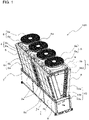
- Fig. 1 is a perspective view illustrating an example of the external structure of the outdoor unit 100 for a refrigeration cycle apparatus according to Embodiment 1.
- the size relationships or the shapes of the components may differ from those of actual ones.
- the same components or parts or components or parts having the same functions have the same reference signs or have no reference signs.
- the positional relationships between the components of the outdoor unit 100 in, for example, an up-down direction, a left-right direction, or a front-rear direction are directions when the outdoor unit 100 is set in a usable state.
- the outdoor unit 100 for a refrigeration cycle apparatus is connected to an indoor unit by heat medium pipes.
- a heat medium such as water or brine is circulated, by, for example, operation of a pump apparatus, between the outdoor unit 100 and the indoor unit.
- high-temperature or low-temperature heat is discharged from a high-temperature or low-temperature heat medium passing through the inside thereof.
- the outdoor unit 100 has an oblong shape in top view.
- a refrigeration cycle apparatus is used for, for example, a large building, a plurality of the outdoor units 100 are disposed side by side in the short-side direction.
- Such an outdoor unit 100 for a refrigeration cycle apparatus is also referred to as a chilling unit and is usable as, for example, a heat source unit for a heat pump apparatus.
- the outdoor unit 100 includes a box 1, which is set on a floor, heat exchangers 3, which are disposed at the top of the box 1, and top frames 5, which are disposed at the top of heat exchange.
- Fans 6 are set on the top frames 5.
- the box 1 has an oblong rectangular shape.
- the box 1 is formed of frames 1a and side walls 1b, which close the spaces between the frames 1a adjacent to each other.
- a machine chamber of the outdoor unit 100 is formed in the internal space of the box 1.
- a compressor, a pressure reducing device, and a water-cooled heat exchanger are accommodated in the machine chamber.
- the compressor, the heat exchangers 3, the pressure reducing device, and the water-cooled heat exchanger are connected by refrigerant pipes to circulate refrigerant. Most of the refrigerant pipes are accommodated in the machine chamber.
- the compressor sucks low-pressure refrigerant and discharges high-pressure refrigerant.
- a scroll compressor is used as the compressor.
- the pressure reducing device decompresses and expands high-pressure liquid refrigerant.
- an expansion valve is used as the pressure reducing device.
- the water-cooled heat exchanger causes heat exchange to be performed between a heat medium and refrigerant flowing in an internal passage thereof.
- a plate heat exchanger is used as the water-cooled heat exchanger.
- the width of the box 1 in the short-side direction is set to be smaller than the width of the top frame 5 in the short-side direction.
- an electrical component box in which, for example, a controller configured to control operation of the compressor and an expansion device is accommodated is accommodated in the machine chamber.
- a controller configured to control operation of the compressor and an expansion device is accommodated
- a microcomputer is used as the controller.
- the drain pan 7 is a water container for discharging drain water produced in the heat exchangers 3 to the outside of the outdoor unit 100.
- the drain pan 7 is disposed at the top of the box 1 and is provided below the heat exchangers 3.
- the drain pan 7 functions as a top plate of the box 1 and partitions off the machine chamber from the space in which the heat exchangers 3 are disposed.
- the drain pan 7 is attached to the frames 1a of the box 1 by screwing or other methods.
- a drain pipe that is connected to the drain pan 7 and through which drain water received by the drain pan 7 is discharged to the outside can be provided in a space below the drain pan 7, that is, closer to the machine chamber.
- the heat exchangers 3 cause heat exchange to be performed between air passing through the heat exchangers 3 and refrigerant flowing in the heat exchangers 3.
- the heat exchangers 3 are set on a heat exchanger setting plate 7a, which will be described later in Fig. 10 , of the drain pan 7.
- the heat exchangers 3 are detachably attached to supports 9 and design panels 10 via attachments attached to the supports 9 and the design panels 10 by screwing or other methods.
- First heat exchangers 3a and second heat exchangers 3b are used as the heat exchangers 3.
- the first heat exchangers 3a and the second heat exchangers 3b are disposed along a pair of edges extending in the long-side direction of the drain pan 7 to face each other with spaces therebetween.
- first heat exchangers 3a and two second heat exchangers 3b are disposed in the outdoor unit 100 in Fig. 1 , but each of the numbers of the first heat exchangers 3a and the second heat exchangers 3b provided therein may be one or three or more.
- an air-cooled finned tube heat exchanger is used as each of the first heat exchanger 3a and the second heat exchanger 3b. Details of the heat exchangers 3 will be described later.
- the first heat exchanger 3a and the second heat exchanger 3b are referred to as the heat exchangers 3 when it is unnecessary to particularly distinguish the first heat exchanger 3a and the second heat exchanger 3b.
- the top frames 5 and the fans 6 form the top of the outdoor unit 100.
- the top frames 5 are each made of a rectangular metal plate and cover the tops of the heat exchangers 3.
- the top frame 5 includes a setting surface 5a, on which the fans 6 are set, and edge surfaces 5b, which extend downward from respective edges of the setting surface 5a.
- the edge surfaces 5b of the top frame 5 extend downward to cover the tops of the heat exchangers 3.
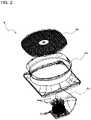
- Fig. 2 is an exploded perspective view of the fan 6 in Fig. 1 .
- Fig. 3 is an enlarged perspective view illustrating part of the structure of the top frame 5 from which the fan 6 has been detached.
- the fan 6 includes a bell mouth 6a, which defines an air passage of the outdoor unit 100, a fan guard 6b, which is disposed at the top of the bell mouth 6a and which has vent holes, and a fan body 6c, which is accommodated in the bell mouth 6a.
- four fans 6 are set on the top frames 5, but the number of the fans 6 is not limited to four as long as the number thereof is one or more.
- an axial fan such as a propeller fan is used as the fan body 6c.
- the setting surface 5a of the top frame 5 has an opening 5a1, which is in communication with the inside of the bell mouth 6a.
- the top frame 5 includes fan setting racks 5c, which cross the opening 5a1 and are attached to the setting surface 5a.
- the fan body 6c is attached to the fan setting rack 5c by screwing or other methods.
- the bell mouth 6a is attached to the setting surface 5a, which is around the opening 5a1, by screwing or other methods.
- Fig. 1 two top frames 5 are provided, and two fans 6 are set on each of the top frames 5.
- the configuration is not limited thereto.
- four top frames 5 may be provided, and one fan 6 may be set on each of the top frames 5.
- one top frame 5 may be provided, and four fans 6 may be set on the top frame 5.
- the top frames 5 can be joined to each other by welding, screwing, or other methods.
- air outside the outdoor unit 100 is guided, from the outside of the outdoor unit 100, into the internal space surrounded by the first heat exchangers 3a, the second heat exchangers 3b, and the drain pan 7 and is subjected to heat exchange in the first heat exchangers 3a and the second heat exchangers 3b.
- the air that has been subjected to heat exchange in the first heat exchangers 3a and the second heat exchangers 3b is blown out from the vent holes of the fan guards 6b via the openings 5a1, which are provided in the respective top frames 5, and the bell mouths 6a. That is, an air passage is formed in the space surrounded by the first heat exchangers 3a, the second heat exchangers 3b, and the drain pan 7 of the outdoor unit 100.
- the first heat exchangers 3a and the second heat exchangers 3b are disposed such that each outer surface of the first heat exchangers 3a and the second heat exchangers 3b, that is, each surface thereof into which air flows, is incliined downward.
- each outer surface of the first heat exchangers 3a and the second heat exchangers 3b that is, each surface thereof into which air flows.
- both the outer surfaces of the first heat exchanger 3a and the second heat exchanger 3b are inclined downward, but the configuration is not limited thereto. It is sufficient that at least one of the outer surfaces of the first heat exchanger 3a and the second heat exchanger 3b be inclined downward.
- Fig. 4 is a side view of a modification example of the outdoor unit 100 in Fig. 1 when viewed in the long-side direction from a side thereof.
- the outdoor unit 100 in Fig. 4 only the outer surface of the second heat exchanger 3b is inclined downward.
- the first heat exchanger 3a is attached in the direction perpendicular to a floor.
- the outdoor unit 100 disposed as the rightmost row can have a configuration in which only the outer surface of the first heat exchanger 3a is inclined downward and in which the second heat exchanger 3b is attached in the direction perpendicular to a floor.
- Fig. 5 is a schematic top view illustrating an example of the disposition pattern of the first heat exchanger 3a and the second heat exchanger 3b of the outdoor unit 100 according to Embodiment 1.
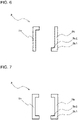
- Fig. 6 illustrates a first modification example of the disposition pattern of the first heat exchanger 3a and the second heat exchanger 3b in Fig. 5 .
- Fig. 7 illustrates a second modification example of the disposition pattern of the first heat exchanger 3a and the second heat exchanger 3b in Fig. 5 .
- Figs. 5 to 7 are schematic views for illustrating the disposition pattern of the first heat exchanger 3a and the second heat exchanger 3b.
- the actual shapes of the first heat exchanger 3a and the second heat exchanger 3b in top view differ from the shapes in Figs. 5 to 7 because at least surfaces thereof into which air flows are inclined downward.
- the first heat exchanger 3a and the second heat exchanger 3b each having a flat shape are disposed so as to face each other.
- two or more first heat exchangers 3a and two or more second heat exchangers 3b have been arranged as rows.
- air that has passed through the first heat exchanger 3a and the second heat exchanger 3b as outer rows passes through the first heat exchanger 3a and the second heat exchanger 3b as inner rows.
- the outdoor unit 100 is increased in size to secure the space in which the first heat exchangers 3a and the second heat exchangers 3b are accommodated.
- Examples of a method for achieving sufficient heat exchange performance without increasing the numbers of the first heat exchangers 3a and the second heat exchangers 3b as rows include a method using the first heat exchanger 3a and the second heat exchanger 3b each having an L shape in Fig. 6 instead of the first heat exchanger 3a and the second heat exchanger 3b each having a flat shape in Fig. 5 .
- the use of the first heat exchanger 3a and the second heat exchanger 3b each having an L shape in Fig. 6 instead of the first heat exchanger 3a and the second heat exchanger 3b each having a flat shape in Fig. 5 enables an increase in the heat exchange region without impairing heat exchange performance.
- Figs. 1 and 4 illustrate examples using the second heat exchanger 3b having an L shape in Fig. 6 .
- first heat exchanger 3a and the second heat exchanger 3b each having a U shape in Fig. 7 instead of the first heat exchangers 3a and the second heat exchangers 3b in Figs. 5 and 6 enables a further increase in the heat exchange region without impairing heat exchange performance.
- Each lower right bent region of the second heat exchangers 3b in Figs. 6 and 7 corresponds to a bent portion 3b1 illustrated in Figs. 8 , 15 , and 16 described later.
- each lower end flat heat exchange region of the second heat exchangers 3b in Figs. 6 and 7 corresponds to a short-side heat exchange region 3b2 illustrated in Figs. 8 , 15 , and 16 described later and in Figs. 1 and 4 .
- the bent portion 3b1 and the short-side heat exchange region 3b2 will be described later.
- the supports 9, which are attached to the drain pan 7 and the top frames 5 and which extend from the drain pan 7 to the top frames 5, are provided in the outdoor unit 100 in Embodiment 1.
- the structure and the disposition of the supports 9 will be described with reference to Figs. 1 and 8 to 12 .
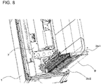
- Fig. 8 is an exploded perspective view illustrating the positional relationship between the second heat exchanger 3b and the support 9 of the outdoor unit 100 in Embodiment 1 when viewed from above the drain pan 7.
- Fig. 9 is a perspective view illustrating an example of the structure of the support 9 in Embodiment 1.
- Fig. 10 is a perspective view illustrating the positional relationship between the drain pan 7 and the supports 9 when viewed from the inside of the outdoor unit 100.
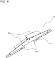
- Fig. 11 is a perspective view illustrating the structure of a base 11 to be attached to the drain pan 7.
- Fig. 12 is a perspective view illustrating the positional relationship between the top frame 5 and the support 9 when viewed from the outside of the outdoor unit 100.
- the supports 9 are capable of supporting the top frame 5 when the heat exchangers 3 are detached.
- the supports 9 are disposed not to interfere with the heat exchangers 3.
- the supports 9 are disposed to support four corners of the setting surface 5a of the top frame 5.
- the support 9 includes a beam 9a, which has an L shape, a first attachment component 9b, and a second attachment component 9c, the first attachment component 9b and the second attachment component 9c being disposed at respective ends of the beam 9a.
- the beam 9a having an L shape enables an increase in the strength of the support 9, whereby the top frame 5 is stably supported.
- the shape of the beam 9a is not limited to an L shape and may be a flat shape as long as the support 9 is capable of stably supporting the top frame 5.
- the drain pan 7 includes the heat exchanger setting plate 7a, on which the heat exchangers 3 are set.
- the heat exchanger setting plate 7a is a metal plate made of stainless steel or other materials and is integrally formed with the drain pan 7.
- the heat exchanger setting plate 7a has a plurality of holes 7b, which guide water droplets produced in the heat exchangers 3 to the drain pan 7.
- the base 11 which includes a body surface 11a having a triangular shape, is attached to the drain pan 7.
- the base 11 includes two attachment plates 11b, which are continuous with the body surface 11a and which are disposed to be apart from each other.
- the base 11 is attached to the drain pan 7 via the attachment plates 11b by screwing, welding, or other methods.
- the base 11 includes support surfaces 11c, which are disposed along oblique sides of the body surface 11a having a triangular shape. As illustrated in Fig. 10 , when the heat exchanger setting plate 7a is set on the support surfaces 11c, upper surfaces of the heat exchanger setting plate 7a are surfaces inclined downward from the center of the outdoor unit 100 toward the outside.
- the second attachment component 9c of the support 9 is attached to the support surface 11c of the base 11 via the heat exchanger setting plate 7a by screwing or other methods.
- the base 11 is also referred to as a pillar and can be integrally formed with the drain pan 7 to serve as part of the drain pan 7.
- the above configuration enables the drain pan 7 to support the heat exchanger 3 such that the outer surface of the heat exchanger 3 is inclined downward.
- the support 9 is supported to extend, along the outer surface of the heat exchanger 3, from the drain pan 7 to the top frame 5.
- the above configuration enables the drain pan 7 to stably support both the heat exchanger 3 and the support 9.
- the first attachment component 9b includes a top frame setting surface 9b1, which is disposed at an end of the beam 9a to form an L shape, and a top frame attachment surface 9b2, which is joined to the top frame setting surface 9b1.
- the top frame setting surface 9b1 supports a lower edge corner 5b1 of the edge surface 5b of the top frame 5.
- the top frame attachment surface 9b2 is attached to the outer side of the edge surface 5b of the top frame 5 by screwing or other methods.
- the support 9 is disposed, along the outer surface of the second heat exchanger 3b, outside the bent portion 3b1 of the second heat exchanger 3b.
- the bent portion 3b1 of the second heat exchanger 3b denotes the boundary region in top view between a heat exchange region of the second heat exchanger 3b extending in the long-side direction of the drain pan 7 and the short-side heat exchange region 3b2 of the second heat exchanger 3b extending in the short-side direction of the drain pan 7.
- the space between fins adjacent to each other of the bent portion 3b1 of the second heat exchanger 3b is larger than that of any other heat exchange region of the second heat exchanger 3b.
- the number of fins of the bent portion 3b1 is smaller than that of any other heat exchange region of the second heat exchanger 3b.
- the support 9 when viewed in the short-side direction of the box 1, the support 9 is inclined from the top frame 5 toward the drain pan 7, is disposed along the outer surface of the second heat exchanger 3b, and is provided at a position that does not interfere with the second heat exchanger 3b.
- the support 9 does not interfere with the second heat exchanger 3b.
- the support 9 does not have to be replaced. Accordingly, the outdoor unit 100 can be formed by using the same support 9. As a result, with the above configuration, it is possible to improve the serviceability of the outdoor unit 100, to reduce the number of man-hours for designing the support 9, and to reduce costs due to the use of the common support 9.
- the support 9 when the support 9 is disposed outside the bent portion 3b1 of the second heat exchanger 3b, it is possible to minimize the amount of airflow that passes through the second heat exchanger 3b and that is blocked by the support 9.
- the space between fins adjacent to each other of the bent portion 3b1 is larger than that of any other heat exchange region of the second heat exchanger 3b, and the number of fins of the bent portion 3b1 is smaller than that of any other heat exchange region of the second heat exchanger 3b. Accordingly, the effect of the bent portion 3b1 on the heat exchange performance of the second heat exchanger 3b is small.
- the support 9 when the support 9 is disposed outside the bent portion 3b1 of the second heat exchanger 3b, it is possible to minimize impairment of the heat exchange performance of the second heat exchanger 3b.
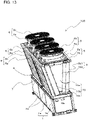
- Fig. 13 illustrates another modification example of the outdoor unit 100 in Fig. 1 .
- the example in which the supports 9 are disposed to support four corners of the setting surface 5a of the top frame 5 has been described above.
- the supports 9 may be disposed to support two corners on a diagonal line of the setting surface 5a of the top frame 5.
- the supports 9 are disposed to support two corners on a diagonal line of the setting surface 5a of the top frame 5, it is possible to reduce the number of components of the outdoor unit 100 and to thus reduce the manufacturing cost of the outdoor unit 100.
- the heat exchanger 3 having an L shape in Fig. 6 or the heat exchanger 3 having a U shape in Fig. 7 is used, for example, it is possible to inhibit ventilation in a part such as the bent portion 3b1 of the second heat exchanger 3b from being prevented by the support 9.
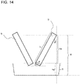
- Fig. 14 is a schematic view illustrating the positional relationship between the drain pan 7 and the supports 9 when the outdoor unit 100 is viewed in the long-side direction from a side of the outdoor unit 100.
- Fig. 15 is a perspective view illustrating the outdoor unit 100 in Fig. 1 from which the supports 9 have been detached.
- Fig. 16 is a perspective view illustrating the outdoor unit 100 in Fig. 15 from which one first heat exchanger 3a has been detached.
- the support 9 is attached to the inside of each of the drain pan 7 and the top frame 5.
- a depth hd of the drain pan 7 has to be adjusted to detach the support 9 from the drain pan 7.
- the dimension from an upper end of the drain pan 7 to a lower end of the top frame 5 is an opening dimension he
- the dimension of a long side of the support 9 is a length L
- the dimension of a short side of the bottom of the support 9 is a length d.
- the inclination of a long side of the support 9 relative to the vertical direction is an angle ⁇
- the inclination of the short side of the support 9 relative to the horizontal direction is an angle ⁇ .
- a distance H from the lower end of the top frame 5 to the bottom of the drain pan 7 is expressed by the sum of the depth hd of the drain pan 7 and the opening dimension he from the upper end of the drain pan 7 to the lower end of the top frame 5.
- a lower part of the outdoor unit 100 has to be detached from the support 9.
- the drain pan 7 is formed such that the depth hd of the drain pan 7 satisfies the expression (3), it is possible to easily detach the support 9 in the workspace between the outdoor units 100 adjacent to each other.
- the variable d of the expression (3) can be small. This further facilitates detachment of the support 9 and enables a size reduction of the drain pan 7. Furthermore, the supports 9 other than the detached support 9 are attached to the top frame 5, and the top frame 5 is thus kept supported by the supports 9.
- the width of the drain pan 7 in the short-side direction is set such that a lower end of the support 9 does not interfere with the upper end of the drain pan 7 during detachment of the support 9.
- the relational expression (3) holds for the case of detachment of the first heat exchanger 3a or the second heat exchanger 3b.
- the depth hd of the drain pan 7 can be calculated by using the expression (3) in which the dimension of a long side of the first heat exchanger 3a is a length L, the dimension of a short side of the bottom of the first heat exchanger 3a is a length d, the inclination of a long side of the first heat exchanger 3a relative to the vertical direction is an angle ⁇ , and the inclination of the short side of the first heat exchanger 3a relative to the horizontal direction is an angle ⁇ .
- the drain pan 7 is formed such that the depth hd of the drain pan 7 satisfies the expression (3), it is possible to easily detach the first heat exchanger 3a in the workspace between the outdoor units 100 adjacent to each other.
- the drain pan 7 is formed such that the depth hd of the drain pan 7 satisfies the expression (3), it is possible to easily detach the second heat exchanger 3b in the workspace between the outdoor units 100 adjacent to each other.
- the top frame 5 is kept supported by the supports 9. Thus, it is possible to replace the first heat exchanger 3a and the second heat exchanger 3b with the top frame 5 attached.
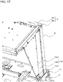
- Fig. 17 is a perspective view illustrating an example of the attachment mode of the design panel 10 different from that in the outdoor unit 100 in Fig. 1 .
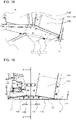
- Fig. 18 is a perspective view illustrating an example of the positional relationship between the design panel 10 and the base 11 when viewed from the inside of the outdoor unit 100.
- the design panel 10 is formed by a main panel 10a, a sub panel 10b, which is attached to a side of the main panel 10a, and a drain pan maintenance panel 10c, which is disposed below the main panel 10a.
- the main panel 10a is formed as a plate-like component having a trapezoidal shape whose upper end is longer than a lower end thereof.
- an upper end of the main panel 10a is attached to the edge surface 5b of the top frame 5 by screwing or other methods.
- a left end of the main panel 10a is joined to the sub panel 10b by screwing or other methods, and a right end of the main panel 10a is joined to the short-side heat exchange region 3b2 of the second heat exchanger 3b.
- the right end of the main panel 10a is joined to the sub panel 10b by screwing or other methods.
- the sub panel 10b is formed as a plate-like component having a quadrilateral shape.
- an upper end of the sub panel 10b is attached to the edge surface 5b of the top frame 5 by screwing or other methods.
- a lower end of the sub panel 10b is set on the base 11.
- a left end of the sub panel 10b is joined to the support 9 by screwing or other methods.
- a right end of the sub panel 10b is joined to the support 9 by screwing or other methods.
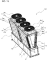
- Fig. 19 is an enlarged front view of the part in Fig. 18 where the drain pan maintenance panel 10c is attached.
- the drain pan maintenance panel 10c is disposed to close the opening formed between the main panel 10a, the sub panel 10b, the base 11, and the short-side heat exchange region 3b2 of the second heat exchanger 3b.
- the drain pan maintenance panel 10c is detachably attached to the main panel 10a by screwing or other methods.
- Provision of the design panel 10 in the outdoor unit 100 enables inhibition of so-called short cycling that airflow blown out from the vent holes of the fan guards 6b is directly taken into the air passage of the outdoor unit 100 without passing through the heat exchangers 3.
- the first heat exchanger 3a and the second heat exchanger 3b each having an L shape in Fig. 6 are used in Fig. 1 .
- the design panel 10 is formed by three panels of the main panel 10a, the sub panel 10b, and the drain pan maintenance panel 10c.
- the short-side heat exchange region 3b2 of the second heat exchanger 3b having an L shape is located between the main panel 10a and the support 9.
- a heat exchange region of the first heat exchanger 3a is formed at the position of the sub panel 10b in Fig. 1 .
- the design panel 10 is formed by the main panel 10a and the drain pan maintenance panel 10c and does not include the sub panel 10b.
- the design panel 10 includes the main panel 10a and the drain pan maintenance panel 10c. Whether a plurality of sub panels 10b, one sub panel 10b, or no sub panel 10b is used can be selected according to the shapes of the first heat exchanger 3a and the second heat exchanger 3b. Thus, the design panel 10 can be formed by combining a plurality of identical panels according to the shapes of the first heat exchanger 3a and the second heat exchanger 3b. Accordingly, in Embodiment 1, manufacture of the main panel 10a, the drain pan maintenance panel 10c, and a plurality of sub panels 10b enables the first heat exchanger 3a and the second heat exchanger 3b to be flexibly replaced and thus enables provision of the outdoor unit 100 having a high degree of freedom in design.
- Fig. 20 is a perspective view illustrating the structure of the drain pan maintenance panel 10c.
- Fig. 21 is a perspective view illustrating an example of the attachment mode of the drain pan maintenance panel 10c when viewed from the inside of the outdoor unit 100.
- Fig. 22 is a sectional view taken along line A-A in Fig. 19 .
- the drain pan maintenance panel 10c is continuous with a guide component 12, which is configured to guide, to the drain pan 7, water droplets flowing from the main panel 10a and the sub panel 10b to the drain pan maintenance panel 10c.
- the guide component 12 is a plate-like component inclined from a joint portion 12b, where the guide component 12 and the drain pan maintenance panel 10c are joined to each other, toward an end portion 12a.
- the guide component 12 is attached to the body surface 11a of the base 11 such that water droplets flow in the space between the guide component 12 and the body surface 11a of the base 11.
- the space between the guide component 12 and the body surface 11a of the base 11 in which water droplets flow is adjusted by changing the joint strength produced by screwing or other methods.
- the guide component 12 is inclined from the joint portion 12b, where the guide component 12 and the drain pan maintenance panel 10c are joined to each other, toward the end portion 12a.
- drain pan maintenance panel 10c When the drain pan maintenance panel 10c is provided with the guide component 12, as represented by solid arrows in Figs. 21 and 22 , paths along which water droplets adhered to an inner surface of the design panel 10 are guided to the drain pan 7 are formed between the guide component 12 and the body surface 11a of the base 11. Water droplets that have dripped from the guide component 12 pass through the space between the two attachment plates 11b, which are illustrated in Fig. 11 and which are disposed to be apart from each other, and flow out to the drain pan 7. Thus, it is possible to inhibit the drain pan 7 and the design panel 10 from being soiled due to water dripping from the design panel 10 or splashes of dripped water.
- drain pan maintenance panel 10c when the drain pan maintenance panel 10c is attached, it is possible to inhibit so-called short cycling that airflow blown out from the vent holes of the fan guards 6b is directly taken into the air passage chamber of the outdoor unit 100. Furthermore, when the drain pan maintenance panel 10c is detached, an opening is formed close to the drain pan 7. Thus, it is possible to facilitate maintenance such as cleaning of the drain pan 7.
Landscapes
- Engineering & Computer Science (AREA)
- Chemical & Material Sciences (AREA)
- Combustion & Propulsion (AREA)
- Mechanical Engineering (AREA)
- General Engineering & Computer Science (AREA)
- Other Air-Conditioning Systems (AREA)
Abstract
Description
- The present disclosure relates to an outdoor unit for a refrigeration cycle apparatus. The outdoor unit is usable as, for example, a heat source unit for a heat pump apparatus.
-
Patent Literature 1 discloses an outdoor unit for a refrigeration cycle apparatus. The outdoor unit includes an oblong box forming a machine chamber, a plurality of heat exchangers set in the long-side direction of the box, and fan guards that are set at the plurality of heat exchangers and that accommodate respective fans. The plurality of heat exchangers are each disposed to face each other. The plurality of heat exchangers are set on the box such that each outer surface thereof faces obliquely downward. - When the outdoor unit for a refrigeration cycle apparatus in
Patent Literature 1 is used for, for example, a large building, a plurality of the outdoor units are disposed side by side in the short-side direction of the box, and spaces are formed between the boxes of the outdoor units adjacent to each other and between the heat exchangers of the outdoor units adjacent to each other. The spaces formed between the boxes of the outdoor units adjacent to each other and between the heat exchangers of the outdoor units adjacent to each other are usable as workspaces for maintenance checks of the outdoor units. - Patent Literature 1: International Publication No.
2011/013672 - A top frame is set on each pair of the plurality of heat exchangers of the outdoor unit for a refrigeration cycle apparatus in
Patent Literature 1. The fan is set on the top frame. Thus, for heat exchanger replacement, the fan has to be detached before the top frame is detached. However, the fan has to be detached in a space above the top frame. Thus, not all the steps of the heat exchanger replacement can be performed in the workspace formed between the outdoor units adjacent to each other. - The present disclosure has been made to solve the above problem, and an object of the present disclosure is to provide an outdoor unit for a refrigeration cycle apparatus, all the steps of heat exchanger replacement being able to be performed in the workspace formed between the outdoor units adjacent to each other.
- An outdoor unit for a refrigeration cycle apparatus according to an embodiment of the present disclosure includes: a heat exchanger having an outer surface inclined downward; a drain pan on which the heat exchanger is set; a top frame on which a fan is set, the top frame being disposed at a top of the heat exchanger; and a support attached to the drain pan and the top frame, the support extending between the drain pan and the top frame.
- The outdoor unit for a refrigeration cycle apparatus according to the embodiment of the present disclosure includes the support joined to the drain pan and the top frame to be located therebetween. Thus, it is possible to attach and detach the heat exchanger in the space between the outdoor units adjacent to each other with the top frame supported by the support. Accordingly, the fan does not have to be detached from the outdoor unit for a refrigeration cycle apparatus according to the embodiment of the present disclosure. As a result, all the steps of heat exchange unit replacement can be performed in the space formed between the outdoor units adjacent to each other.
-
- [
Fig. 1] Fig. 1 is a perspective view illustrating an example of the external structure of an outdoor unit for a refrigeration cycle apparatus according toEmbodiment 1. - [
Fig. 2] Fig. 2 is an exploded perspective view of a fan inFig. 1 . - [
Fig. 3] Fig. 3 is an enlarged perspective view illustrating part of the structure of a top frame from which a fan has been detached. - [
Fig. 4] Fig. 4 is a side view of a modification example of the outdoor unit inFig. 1 when viewed in the long-side direction from a side thereof. - [
Fig. 5] Fig. 5 is a schematic top view illustrating an example of the disposition pattern of a first heat exchanger and a second heat exchanger of the outdoor unit according toEmbodiment 1. - [
Fig. 6] Fig. 6 illustrates a first modification example of the disposition pattern of the first heat exchanger and the second heat exchanger inFig. 5 . - [
Fig. 7] Fig. 7 illustrates a second modification example of the disposition pattern of the first heat exchanger and the second heat exchanger inFig. 5 . - [
Fig. 8] Fig. 8 is an exploded view illustrating the positional relationship between the second heat exchanger and a support of the outdoor unit inEmbodiment 1. - [
Fig. 9] Fig. 9 is a perspective view illustrating an example of the structure of the support inEmbodiment 1. - [
Fig. 10] Fig. 10 is a perspective view illustrating the positional relationship between a drain pan and the supports when viewed from the inside of the outdoor unit. - [
Fig. 11] Fig. 11 is a perspective view illustrating the structure of a base to be attached to the drain pan. - [
Fig. 12] Fig. 12 is a perspective view illustrating the positional relationship between the top frame and the support when viewed from the outside of the outdoor unit. - [
Fig. 13] Fig. 13 illustrates another modification example of the outdoor unit inFig. 1 . - [
Fig. 14] Fig. 14 is a schematic view illustrating the positional relationship between the drain pan and the supports when the outdoor unit is viewed in the long-side direction from a side of the outdoor unit. - [
Fig. 15] Fig. 15 is a perspective view illustrating the outdoor unit inFig. 1 from which the supports have been detached. - [
Fig. 16] Fig. 16 is a perspective view illustrating the outdoor unit inFig. 15 from which one first heat exchanger has been detached. - [
Fig. 17] Fig. 17 is a perspective view illustrating an example of the attachment mode of a design panel different from that in the outdoor unit inFig. 1 . - [
Fig. 18] Fig. 18 is a perspective view illustrating an example of the positional relationship between the design panel and the base when viewed from the inside of the outdoor unit. - [
Fig. 19] Fig. 19 is an enlarged front view of the part inFig. 18 where a drain pan maintenance panel is attached. - [
Fig. 20] Fig. 20 is a perspective view illustrating the structure of the drain pan maintenance panel. - [
Fig. 21] Fig. 21 is a perspective view illustrating an example of the attachment mode of the drain pan maintenance panel when viewed from the inside of the outdoor unit. - [
Fig. 22] Fig. 22 is a sectional view taken along line A-A inFig. 19 . - An
outdoor unit 100 for a refrigeration cycle apparatus according to Embodiment 1 will be described.Fig. 1 is a perspective view illustrating an example of the external structure of theoutdoor unit 100 for a refrigeration cycle apparatus according toEmbodiment 1. In the following drawings includingFig. 1 , the size relationships or the shapes of the components may differ from those of actual ones. In addition, in the following drawings, the same components or parts or components or parts having the same functions have the same reference signs or have no reference signs. Basically, the positional relationships between the components of theoutdoor unit 100 in, for example, an up-down direction, a left-right direction, or a front-rear direction are directions when theoutdoor unit 100 is set in a usable state. - Although not illustrated, the
outdoor unit 100 for a refrigeration cycle apparatus is connected to an indoor unit by heat medium pipes. A heat medium such as water or brine is circulated, by, for example, operation of a pump apparatus, between theoutdoor unit 100 and the indoor unit. In theoutdoor unit 100, high-temperature or low-temperature heat is discharged from a high-temperature or low-temperature heat medium passing through the inside thereof. Theoutdoor unit 100 has an oblong shape in top view. When a refrigeration cycle apparatus is used for, for example, a large building, a plurality of theoutdoor units 100 are disposed side by side in the short-side direction. Such anoutdoor unit 100 for a refrigeration cycle apparatus is also referred to as a chilling unit and is usable as, for example, a heat source unit for a heat pump apparatus. - The
outdoor unit 100 includes abox 1, which is set on a floor,heat exchangers 3, which are disposed at the top of thebox 1, andtop frames 5, which are disposed at the top of heat exchange. Adrain pan 7, on which theheat exchangers 3 are set, is disposed at the top of thebox 1.Fans 6 are set on thetop frames 5. - The
box 1 has an oblong rectangular shape. Thebox 1 is formed offrames 1a andside walls 1b, which close the spaces between theframes 1a adjacent to each other. A machine chamber of theoutdoor unit 100 is formed in the internal space of thebox 1. Although not illustrated, for example, a compressor, a pressure reducing device, and a water-cooled heat exchanger are accommodated in the machine chamber. The compressor, theheat exchangers 3, the pressure reducing device, and the water-cooled heat exchanger are connected by refrigerant pipes to circulate refrigerant. Most of the refrigerant pipes are accommodated in the machine chamber. The compressor sucks low-pressure refrigerant and discharges high-pressure refrigerant. For example, a scroll compressor is used as the compressor. The pressure reducing device decompresses and expands high-pressure liquid refrigerant. For example, an expansion valve is used as the pressure reducing device. The water-cooled heat exchanger causes heat exchange to be performed between a heat medium and refrigerant flowing in an internal passage thereof. For example, a plate heat exchanger is used as the water-cooled heat exchanger. The width of thebox 1 in the short-side direction is set to be smaller than the width of thetop frame 5 in the short-side direction. - In addition, although not illustrated, an electrical component box in which, for example, a controller configured to control operation of the compressor and an expansion device is accommodated is accommodated in the machine chamber. For example, a microcomputer is used as the controller.
- The
drain pan 7 is a water container for discharging drain water produced in theheat exchangers 3 to the outside of theoutdoor unit 100. Thedrain pan 7 is disposed at the top of thebox 1 and is provided below theheat exchangers 3. In addition, thedrain pan 7 functions as a top plate of thebox 1 and partitions off the machine chamber from the space in which theheat exchangers 3 are disposed. For example, thedrain pan 7 is attached to theframes 1a of thebox 1 by screwing or other methods. Although not illustrated, a drain pipe that is connected to thedrain pan 7 and through which drain water received by thedrain pan 7 is discharged to the outside can be provided in a space below thedrain pan 7, that is, closer to the machine chamber. - The
heat exchangers 3 cause heat exchange to be performed between air passing through theheat exchangers 3 and refrigerant flowing in theheat exchangers 3. Theheat exchangers 3 are set on a heatexchanger setting plate 7a, which will be described later inFig. 10 , of thedrain pan 7. Although not illustrated, for example, theheat exchangers 3 are detachably attached tosupports 9 anddesign panels 10 via attachments attached to thesupports 9 and thedesign panels 10 by screwing or other methods.First heat exchangers 3a andsecond heat exchangers 3b are used as theheat exchangers 3. Thefirst heat exchangers 3a and thesecond heat exchangers 3b are disposed along a pair of edges extending in the long-side direction of thedrain pan 7 to face each other with spaces therebetween. Twofirst heat exchangers 3a and twosecond heat exchangers 3b are disposed in theoutdoor unit 100 inFig. 1 , but each of the numbers of thefirst heat exchangers 3a and thesecond heat exchangers 3b provided therein may be one or three or more. For example, an air-cooled finned tube heat exchanger is used as each of thefirst heat exchanger 3a and thesecond heat exchanger 3b. Details of theheat exchangers 3 will be described later. In the following description, thefirst heat exchanger 3a and thesecond heat exchanger 3b are referred to as theheat exchangers 3 when it is unnecessary to particularly distinguish thefirst heat exchanger 3a and thesecond heat exchanger 3b. - The top frames 5 and the
fans 6 form the top of theoutdoor unit 100. The top frames 5 are each made of a rectangular metal plate and cover the tops of theheat exchangers 3. Thetop frame 5 includes asetting surface 5a, on which thefans 6 are set, andedge surfaces 5b, which extend downward from respective edges of the settingsurface 5a. The edge surfaces 5b of thetop frame 5 extend downward to cover the tops of theheat exchangers 3. -
Fig. 2 is an exploded perspective view of thefan 6 inFig. 1 .Fig. 3 is an enlarged perspective view illustrating part of the structure of thetop frame 5 from which thefan 6 has been detached. Thefan 6 includes abell mouth 6a, which defines an air passage of theoutdoor unit 100, afan guard 6b, which is disposed at the top of thebell mouth 6a and which has vent holes, and afan body 6c, which is accommodated in thebell mouth 6a. InFig. 1 , fourfans 6 are set on the top frames 5, but the number of thefans 6 is not limited to four as long as the number thereof is one or more. For example, an axial fan such as a propeller fan is used as thefan body 6c. - The setting
surface 5a of thetop frame 5 has an opening 5a1, which is in communication with the inside of thebell mouth 6a. Thetop frame 5 includes fan setting racks 5c, which cross the opening 5a1 and are attached to thesetting surface 5a. Thefan body 6c is attached to thefan setting rack 5c by screwing or other methods. Thebell mouth 6a is attached to thesetting surface 5a, which is around the opening 5a1, by screwing or other methods. InFig. 1 , twotop frames 5 are provided, and twofans 6 are set on each of the top frames 5. However, the configuration is not limited thereto. For example, fourtop frames 5 may be provided, and onefan 6 may be set on each of the top frames 5. Alternatively, onetop frame 5 may be provided, and fourfans 6 may be set on thetop frame 5. When a plurality oftop frames 5 are provided, thetop frames 5 can be joined to each other by welding, screwing, or other methods. - By rotation of the
fan bodies 6c, air outside theoutdoor unit 100 is guided, from the outside of theoutdoor unit 100, into the internal space surrounded by thefirst heat exchangers 3a, thesecond heat exchangers 3b, and thedrain pan 7 and is subjected to heat exchange in thefirst heat exchangers 3a and thesecond heat exchangers 3b. The air that has been subjected to heat exchange in thefirst heat exchangers 3a and thesecond heat exchangers 3b is blown out from the vent holes of the fan guards 6b via the openings 5a1, which are provided in the respectivetop frames 5, and thebell mouths 6a. That is, an air passage is formed in the space surrounded by thefirst heat exchangers 3a, thesecond heat exchangers 3b, and thedrain pan 7 of theoutdoor unit 100. - Next, the disposition and the configuration of the
heat exchangers 3 will be described with reference toFig. 1 . - In
Fig. 1 , thefirst heat exchangers 3a and thesecond heat exchangers 3b are disposed such that each outer surface of thefirst heat exchangers 3a and thesecond heat exchangers 3b, that is, each surface thereof into which air flows, is incliined downward. Thus, when a plurality of theoutdoor units 100 are disposed side by side in the short-side direction, an inverted V-shaped space is formed between theheat exchangers 3 of theoutdoor units 100 adjacent to each other, and airflow can be guided, from the inverted V-shaped space, into thefirst heat exchangers 3a and thesecond heat exchangers 3b. Accordingly, even when a plurality of theoutdoor units 100 are disposed side by side in the short-side direction of thebox 1, a space does not have to be provided between thetop frames 5 adjacent to each other. As a result, it is possible to effectively use the space in which theoutdoor units 100 are disposed. In addition, as described above, since the width of thebox 1 in the short-side direction is set to be smaller than the width of thetop frame 5 in the short-side direction, a space is formed between theboxes 1 of theoutdoor units 100 adjacent to each other. As a result, it is possible to secure a workspace for, for example, maintenance checks of the machine chambers. - In the
outdoor unit 100 inFig. 1 , both the outer surfaces of thefirst heat exchanger 3a and thesecond heat exchanger 3b are inclined downward, but the configuration is not limited thereto. It is sufficient that at least one of the outer surfaces of thefirst heat exchanger 3a and thesecond heat exchanger 3b be inclined downward. -
Fig. 4 is a side view of a modification example of theoutdoor unit 100 inFig. 1 when viewed in the long-side direction from a side thereof. In theoutdoor unit 100 inFig. 4 , only the outer surface of thesecond heat exchanger 3b is inclined downward. Thefirst heat exchanger 3a is attached in the direction perpendicular to a floor. When a plurality of theoutdoor units 100 are disposed side by side in the short-side direction, and theoutdoor unit 100 inFig. 4 is disposed as the leftmost row, it is possible to inhibit a space that cannot be effectively used from being formed at the left of theoutdoor unit 100 inFig. 4 . In addition, when a plurality of theoutdoor units 100 are disposed side by side in the short-side direction, theoutdoor unit 100 disposed as the rightmost row can have a configuration in which only the outer surface of thefirst heat exchanger 3a is inclined downward and in which thesecond heat exchanger 3b is attached in the direction perpendicular to a floor. -
Fig. 5 is a schematic top view illustrating an example of the disposition pattern of thefirst heat exchanger 3a and thesecond heat exchanger 3b of theoutdoor unit 100 according toEmbodiment 1.Fig. 6 illustrates a first modification example of the disposition pattern of thefirst heat exchanger 3a and thesecond heat exchanger 3b inFig. 5 .Fig. 7 illustrates a second modification example of the disposition pattern of thefirst heat exchanger 3a and thesecond heat exchanger 3b inFig. 5 .Figs. 5 to 7 are schematic views for illustrating the disposition pattern of thefirst heat exchanger 3a and thesecond heat exchanger 3b. The actual shapes of thefirst heat exchanger 3a and thesecond heat exchanger 3b in top view differ from the shapes inFigs. 5 to 7 because at least surfaces thereof into which air flows are inclined downward. - In
Fig. 5 , thefirst heat exchanger 3a and thesecond heat exchanger 3b each having a flat shape are disposed so as to face each other. To improve the heat exchange performance of thefirst heat exchanger 3a and thesecond heat exchanger 3b, two or morefirst heat exchangers 3a and two or moresecond heat exchangers 3b have been arranged as rows. However, air that has passed through thefirst heat exchanger 3a and thesecond heat exchanger 3b as outer rows passes through thefirst heat exchanger 3a and thesecond heat exchanger 3b as inner rows. Thus, there has been a case in which sufficient heat exchange performance cannot be achieved. In addition, there has been a case in which theoutdoor unit 100 is increased in size to secure the space in which thefirst heat exchangers 3a and thesecond heat exchangers 3b are accommodated. - Examples of a method for achieving sufficient heat exchange performance without increasing the numbers of the
first heat exchangers 3a and thesecond heat exchangers 3b as rows include a method using thefirst heat exchanger 3a and thesecond heat exchanger 3b each having an L shape inFig. 6 instead of thefirst heat exchanger 3a and thesecond heat exchanger 3b each having a flat shape inFig. 5 . The use of thefirst heat exchanger 3a and thesecond heat exchanger 3b each having an L shape inFig. 6 instead of thefirst heat exchanger 3a and thesecond heat exchanger 3b each having a flat shape inFig. 5 enables an increase in the heat exchange region without impairing heat exchange performance.Figs. 1 and4 illustrate examples using thesecond heat exchanger 3b having an L shape inFig. 6 . - In addition, the use of the
first heat exchanger 3a and thesecond heat exchanger 3b each having a U shape inFig. 7 instead of thefirst heat exchangers 3a and thesecond heat exchangers 3b inFigs. 5 and6 enables a further increase in the heat exchange region without impairing heat exchange performance. - Each lower right bent region of the
second heat exchangers 3b inFigs. 6 and 7 corresponds to a bent portion 3b1 illustrated inFigs. 8 ,15 , and16 described later. In addition, each lower end flat heat exchange region of thesecond heat exchangers 3b inFigs. 6 and 7 corresponds to a short-side heat exchange region 3b2 illustrated inFigs. 8 ,15 , and16 described later and inFigs. 1 and4 . The bent portion 3b1 and the short-side heat exchange region 3b2 will be described later. - To facilitate replacement of the
first heat exchangers 3a and thesecond heat exchangers 3b, thesupports 9, which are attached to thedrain pan 7 and thetop frames 5 and which extend from thedrain pan 7 to the top frames 5, are provided in theoutdoor unit 100 inEmbodiment 1. The structure and the disposition of thesupports 9 will be described with reference toFigs. 1 and8 to 12 . -
Fig. 8 is an exploded perspective view illustrating the positional relationship between thesecond heat exchanger 3b and thesupport 9 of theoutdoor unit 100 inEmbodiment 1 when viewed from above thedrain pan 7.Fig. 9 is a perspective view illustrating an example of the structure of thesupport 9 inEmbodiment 1.Fig. 10 is a perspective view illustrating the positional relationship between thedrain pan 7 and thesupports 9 when viewed from the inside of theoutdoor unit 100.Fig. 11 is a perspective view illustrating the structure of a base 11 to be attached to thedrain pan 7.Fig. 12 is a perspective view illustrating the positional relationship between thetop frame 5 and thesupport 9 when viewed from the outside of theoutdoor unit 100. - The
supports 9 are capable of supporting thetop frame 5 when theheat exchangers 3 are detached. Thesupports 9 are disposed not to interfere with theheat exchangers 3. For example, thesupports 9 are disposed to support four corners of the settingsurface 5a of thetop frame 5. - As illustrated in
Fig. 9 , for example, thesupport 9 includes abeam 9a, which has an L shape, afirst attachment component 9b, and asecond attachment component 9c, thefirst attachment component 9b and thesecond attachment component 9c being disposed at respective ends of thebeam 9a. Thebeam 9a having an L shape enables an increase in the strength of thesupport 9, whereby thetop frame 5 is stably supported. The shape of thebeam 9a is not limited to an L shape and may be a flat shape as long as thesupport 9 is capable of stably supporting thetop frame 5. - As illustrated in
Fig. 10 , thedrain pan 7 includes the heatexchanger setting plate 7a, on which theheat exchangers 3 are set. For example, the heatexchanger setting plate 7a is a metal plate made of stainless steel or other materials and is integrally formed with thedrain pan 7. The heatexchanger setting plate 7a has a plurality ofholes 7b, which guide water droplets produced in theheat exchangers 3 to thedrain pan 7. - In addition, the
base 11, which includes abody surface 11a having a triangular shape, is attached to thedrain pan 7. As illustrated inFig. 11 , thebase 11 includes twoattachment plates 11b, which are continuous with thebody surface 11a and which are disposed to be apart from each other. Thebase 11 is attached to thedrain pan 7 via theattachment plates 11b by screwing, welding, or other methods. - In addition, as illustrated in
Figs. 10 and11 , thebase 11 includes support surfaces 11c, which are disposed along oblique sides of thebody surface 11a having a triangular shape. As illustrated inFig. 10 , when the heatexchanger setting plate 7a is set on the support surfaces 11c, upper surfaces of the heatexchanger setting plate 7a are surfaces inclined downward from the center of theoutdoor unit 100 toward the outside. Thesecond attachment component 9c of thesupport 9 is attached to thesupport surface 11c of thebase 11 via the heatexchanger setting plate 7a by screwing or other methods. Thebase 11 is also referred to as a pillar and can be integrally formed with thedrain pan 7 to serve as part of thedrain pan 7. - The above configuration enables the
drain pan 7 to support theheat exchanger 3 such that the outer surface of theheat exchanger 3 is inclined downward. In addition, with the above configuration, thesupport 9 is supported to extend, along the outer surface of theheat exchanger 3, from thedrain pan 7 to thetop frame 5. Thus, the above configuration enables thedrain pan 7 to stably support both theheat exchanger 3 and thesupport 9. - As illustrated in
Figs. 9 and12 , thefirst attachment component 9b includes a top frame setting surface 9b1, which is disposed at an end of thebeam 9a to form an L shape, and a top frame attachment surface 9b2, which is joined to the top frame setting surface 9b1. The top frame setting surface 9b1 supports a lower edge corner 5b1 of theedge surface 5b of thetop frame 5. The top frame attachment surface 9b2 is attached to the outer side of theedge surface 5b of thetop frame 5 by screwing or other methods. - As illustrated in
Fig. 8 , thesupport 9 is disposed, along the outer surface of thesecond heat exchanger 3b, outside the bent portion 3b1 of thesecond heat exchanger 3b. Here, the bent portion 3b1 of thesecond heat exchanger 3b denotes the boundary region in top view between a heat exchange region of thesecond heat exchanger 3b extending in the long-side direction of thedrain pan 7 and the short-side heat exchange region 3b2 of thesecond heat exchanger 3b extending in the short-side direction of thedrain pan 7. The space between fins adjacent to each other of the bent portion 3b1 of thesecond heat exchanger 3b is larger than that of any other heat exchange region of thesecond heat exchanger 3b. The number of fins of the bent portion 3b1 is smaller than that of any other heat exchange region of thesecond heat exchanger 3b. - As illustrated in
Fig. 1 , when viewed in the short-side direction of thebox 1, thesupport 9 is inclined from thetop frame 5 toward thedrain pan 7, is disposed along the outer surface of thesecond heat exchanger 3b, and is provided at a position that does not interfere with thesecond heat exchanger 3b. - With the above configuration, even when the
second heat exchanger 3b inFig. 8 , that is, thesecond heat exchanger 3b having an L shape inFig. 6 , is replaced with thesecond heat exchanger 3b having a flat shape inFig. 5 or thesecond heat exchanger 3b having a U shape inFig. 7 , thesupport 9 does not interfere with thesecond heat exchanger 3b. Thus, even when thesecond heat exchanger 3b is changed, thesupport 9 does not have to be replaced. Accordingly, theoutdoor unit 100 can be formed by using thesame support 9. As a result, with the above configuration, it is possible to improve the serviceability of theoutdoor unit 100, to reduce the number of man-hours for designing thesupport 9, and to reduce costs due to the use of thecommon support 9. - In addition, when the
support 9 is disposed outside the bent portion 3b1 of thesecond heat exchanger 3b, it is possible to minimize the amount of airflow that passes through thesecond heat exchanger 3b and that is blocked by thesupport 9. The space between fins adjacent to each other of the bent portion 3b1 is larger than that of any other heat exchange region of thesecond heat exchanger 3b, and the number of fins of the bent portion 3b1 is smaller than that of any other heat exchange region of thesecond heat exchanger 3b. Accordingly, the effect of the bent portion 3b1 on the heat exchange performance of thesecond heat exchanger 3b is small. Thus, when thesupport 9 is disposed outside the bent portion 3b1 of thesecond heat exchanger 3b, it is possible to minimize impairment of the heat exchange performance of thesecond heat exchanger 3b. -
Fig. 13 illustrates another modification example of theoutdoor unit 100 inFig. 1 . The example in which thesupports 9 are disposed to support four corners of the settingsurface 5a of thetop frame 5 has been described above. For example, as illustrated inFig. 13 , thesupports 9 may be disposed to support two corners on a diagonal line of the settingsurface 5a of thetop frame 5. When thesupports 9 are disposed to support two corners on a diagonal line of the settingsurface 5a of thetop frame 5, it is possible to reduce the number of components of theoutdoor unit 100 and to thus reduce the manufacturing cost of theoutdoor unit 100. In addition, when theheat exchanger 3 having an L shape inFig. 6 or theheat exchanger 3 having a U shape inFig. 7 is used, for example, it is possible to inhibit ventilation in a part such as the bent portion 3b1 of thesecond heat exchanger 3b from being prevented by thesupport 9. -
Fig. 14 is a schematic view illustrating the positional relationship between thedrain pan 7 and thesupports 9 when theoutdoor unit 100 is viewed in the long-side direction from a side of theoutdoor unit 100.Fig. 15 is a perspective view illustrating theoutdoor unit 100 inFig. 1 from which thesupports 9 have been detached.Fig. 16 is a perspective view illustrating theoutdoor unit 100 inFig. 15 from which onefirst heat exchanger 3a has been detached. - As described above, the
support 9 is attached to the inside of each of thedrain pan 7 and thetop frame 5. Thus, a depth hd of thedrain pan 7 has to be adjusted to detach thesupport 9 from thedrain pan 7. - In the following description, the dimension from an upper end of the
drain pan 7 to a lower end of thetop frame 5 is an opening dimension he, the dimension of a long side of thesupport 9 is a length L, and the dimension of a short side of the bottom of thesupport 9 is a length d. In addition, the inclination of a long side of thesupport 9 relative to the vertical direction is an angle θ, and the inclination of the short side of thesupport 9 relative to the horizontal direction is an angle α. - A distance H from the lower end of the
top frame 5 to the bottom of thedrain pan 7 is expressed by the sum of the depth hd of thedrain pan 7 and the opening dimension he from the upper end of thedrain pan 7 to the lower end of thetop frame 5. To detach thesupport 9 in the workspace between theoutdoor units 100 adjacent to each other, first, a lower part of theoutdoor unit 100 has to be detached from thesupport 9. Thus, the distance H from the lower end of thetop frame 5 to the bottom of thedrain pan 7 has to be larger than the length L of the long side of thesupport 9. Accordingly, the relationship between the distance H from the lower end of thetop frame 5 to the bottom of thedrain pan 7 and the length L of the long side of thesupport 9 is expressed by an expression (1):
- On the other hand, in view of the relationship illustrated in
Fig. 14 , the opening dimension he from the upper end of thedrain pan 7 to the lower end of thetop frame 5 is expressed by the following expression.
- Thus, the following relational expression (3) holds when the expression (2) is substituted into the expression (1):

- Accordingly, when the
drain pan 7 is formed such that the depth hd of thedrain pan 7 satisfies the expression (3), it is possible to easily detach thesupport 9 in the workspace between theoutdoor units 100 adjacent to each other. - In addition, when the length of the short side of the bottom of the
support 9 is smaller than the length of a short side of the top of thesupport 9, the variable d of the expression (3) can be small. This further facilitates detachment of thesupport 9 and enables a size reduction of thedrain pan 7. Furthermore, thesupports 9 other than thedetached support 9 are attached to thetop frame 5, and thetop frame 5 is thus kept supported by thesupports 9. The width of thedrain pan 7 in the short-side direction is set such that a lower end of thesupport 9 does not interfere with the upper end of thedrain pan 7 during detachment of thesupport 9. - Similarly, the relational expression (3) holds for the case of detachment of the
first heat exchanger 3a or thesecond heat exchanger 3b. For example, the depth hd of thedrain pan 7 can be calculated by using the expression (3) in which the dimension of a long side of thefirst heat exchanger 3a is a length L, the dimension of a short side of the bottom of thefirst heat exchanger 3a is a length d, the inclination of a long side of thefirst heat exchanger 3a relative to the vertical direction is an angle θ, and the inclination of the short side of thefirst heat exchanger 3a relative to the horizontal direction is an angle α. Then, when thedrain pan 7 is formed such that the depth hd of thedrain pan 7 satisfies the expression (3), it is possible to easily detach thefirst heat exchanger 3a in the workspace between theoutdoor units 100 adjacent to each other. In addition, when thedrain pan 7 is formed such that the depth hd of thedrain pan 7 satisfies the expression (3), it is possible to easily detach thesecond heat exchanger 3b in the workspace between theoutdoor units 100 adjacent to each other. In this case, thetop frame 5 is kept supported by thesupports 9. Thus, it is possible to replace thefirst heat exchanger 3a and thesecond heat exchanger 3b with thetop frame 5 attached. - Next, the
design panel 10, which is attached between thefirst heat exchanger 3a and thesecond heat exchanger 3b and which forms some of the contours of theoutdoor unit 100, will be described with reference toFigs. 1 ,17 , and18 . -
Fig. 17 is a perspective view illustrating an example of the attachment mode of thedesign panel 10 different from that in theoutdoor unit 100 inFig. 1 .Fig. 18 is a perspective view illustrating an example of the positional relationship between thedesign panel 10 and the base 11 when viewed from the inside of theoutdoor unit 100. - The
design panel 10 is formed by amain panel 10a, asub panel 10b, which is attached to a side of themain panel 10a, and a drainpan maintenance panel 10c, which is disposed below themain panel 10a. For example, themain panel 10a is formed as a plate-like component having a trapezoidal shape whose upper end is longer than a lower end thereof. For example, an upper end of themain panel 10a is attached to theedge surface 5b of thetop frame 5 by screwing or other methods. In the example of theoutdoor unit 100 inFig. 1 , a left end of themain panel 10a is joined to thesub panel 10b by screwing or other methods, and a right end of themain panel 10a is joined to the short-side heat exchange region 3b2 of thesecond heat exchanger 3b. In the example inFig. 17 , the right end of themain panel 10a is joined to thesub panel 10b by screwing or other methods. - For example, the
sub panel 10b is formed as a plate-like component having a quadrilateral shape. For example, an upper end of thesub panel 10b is attached to theedge surface 5b of thetop frame 5 by screwing or other methods. As illustrated inFig. 18 , a lower end of thesub panel 10b is set on thebase 11. In the example of theoutdoor unit 100 inFig. 1 , a left end of thesub panel 10b is joined to thesupport 9 by screwing or other methods. In the example inFig. 17 , a right end of thesub panel 10b is joined to thesupport 9 by screwing or other methods. -
Fig. 19 is an enlarged front view of the part inFig. 18 where the drainpan maintenance panel 10c is attached. The drainpan maintenance panel 10c is disposed to close the opening formed between themain panel 10a, thesub panel 10b, thebase 11, and the short-side heat exchange region 3b2 of thesecond heat exchanger 3b. As illustrated inFig. 19 , for example, the drainpan maintenance panel 10c is detachably attached to themain panel 10a by screwing or other methods. - Provision of the
design panel 10 in theoutdoor unit 100 enables inhibition of so-called short cycling that airflow blown out from the vent holes of thefan guards 6b is directly taken into the air passage of theoutdoor unit 100 without passing through theheat exchangers 3. - The
first heat exchanger 3a and thesecond heat exchanger 3b each having an L shape inFig. 6 are used inFig. 1 . Thus, thedesign panel 10 is formed by three panels of themain panel 10a, thesub panel 10b, and the drainpan maintenance panel 10c. In the case inFig. 1 , the short-side heat exchange region 3b2 of thesecond heat exchanger 3b having an L shape is located between themain panel 10a and thesupport 9. - On the other hand, when the
second heat exchanger 3b having a flat shape inFig. 5 is used inFig. 1 , there is no region corresponding to the short-side heat exchange region 3b2 of thesecond heat exchanger 3b having an L shape inFigs. 1 and6 . Thus, the space between themain panel 10a and thesupport 9 has to be closed to prevent short cycling of airflow. However, the space between the left end of themain panel 10a and thesupport 9 can be closed with a panel shaped to form a pair with thesub panel 10b. - In addition, when the
first heat exchanger 3a having a U shape inFig. 7 is used inFig. 1 , a heat exchange region of thefirst heat exchanger 3a, the heat exchange region being not illustrated and being shaped to form a pair with the short-side heat exchange region 3b2, is formed at the position of thesub panel 10b inFig. 1 . Thus, thedesign panel 10 is formed by themain panel 10a and the drainpan maintenance panel 10c and does not include thesub panel 10b. - As described above, the
design panel 10 includes themain panel 10a and the drainpan maintenance panel 10c. Whether a plurality ofsub panels 10b, onesub panel 10b, or nosub panel 10b is used can be selected according to the shapes of thefirst heat exchanger 3a and thesecond heat exchanger 3b. Thus, thedesign panel 10 can be formed by combining a plurality of identical panels according to the shapes of thefirst heat exchanger 3a and thesecond heat exchanger 3b. Accordingly, inEmbodiment 1, manufacture of themain panel 10a, the drainpan maintenance panel 10c, and a plurality ofsub panels 10b enables thefirst heat exchanger 3a and thesecond heat exchanger 3b to be flexibly replaced and thus enables provision of theoutdoor unit 100 having a high degree of freedom in design. -
Fig. 20 is a perspective view illustrating the structure of the drainpan maintenance panel 10c.Fig. 21 is a perspective view illustrating an example of the attachment mode of the drainpan maintenance panel 10c when viewed from the inside of theoutdoor unit 100.Fig. 22 is a sectional view taken along line A-A inFig. 19 . The drainpan maintenance panel 10c is continuous with aguide component 12, which is configured to guide, to thedrain pan 7, water droplets flowing from themain panel 10a and thesub panel 10b to the drainpan maintenance panel 10c. Theguide component 12 is a plate-like component inclined from ajoint portion 12b, where theguide component 12 and the drainpan maintenance panel 10c are joined to each other, toward anend portion 12a. Theguide component 12 is attached to thebody surface 11a of the base 11 such that water droplets flow in the space between theguide component 12 and thebody surface 11a of thebase 11. For example, the space between theguide component 12 and thebody surface 11a of the base 11 in which water droplets flow is adjusted by changing the joint strength produced by screwing or other methods. Theguide component 12 is inclined from thejoint portion 12b, where theguide component 12 and the drainpan maintenance panel 10c are joined to each other, toward theend portion 12a. - When the drain
pan maintenance panel 10c is provided with theguide component 12, as represented by solid arrows inFigs. 21 and22 , paths along which water droplets adhered to an inner surface of thedesign panel 10 are guided to thedrain pan 7 are formed between theguide component 12 and thebody surface 11a of thebase 11. Water droplets that have dripped from theguide component 12 pass through the space between the twoattachment plates 11b, which are illustrated inFig. 11 and which are disposed to be apart from each other, and flow out to thedrain pan 7. Thus, it is possible to inhibit thedrain pan 7 and thedesign panel 10 from being soiled due to water dripping from thedesign panel 10 or splashes of dripped water. In addition, when the drainpan maintenance panel 10c is attached, it is possible to inhibit so-called short cycling that airflow blown out from the vent holes of thefan guards 6b is directly taken into the air passage chamber of theoutdoor unit 100. Furthermore, when the drainpan maintenance panel 10c is detached, an opening is formed close to thedrain pan 7. Thus, it is possible to facilitate maintenance such as cleaning of thedrain pan 7. - 1: box, 1a: frame, 1b: side wall, 3: heat exchanger, 3a: first heat exchanger, 3b: second heat exchanger, 3b1: bent portion, 3b2: short-side heat exchange region, 5: top frame, 5a: setting surface, 5a1: opening, 5b: edge surface, 5b1: lower edge corner, 5c: fan setting rack, 6: fan, 6a: bell mouth, 6b: fan guard, 6c: fan body, 7: drain pan, 7a: heat exchanger setting plate, 7b: hole, 9: support, 9a: beam, 9b: first attachment component, 9b1: top frame setting surface, 9b2: top frame attachment surface, 9c: second attachment component, 10: design panel, 10a: main panel, 10b: sub panel, 10c: drain pan maintenance panel, 11: base, 11a: body surface, 11b: attachment plate, 11c: support surface, 12: guide component, 12a: end portion, 12b: joint portion, 100: outdoor unit
Claims (9)
- An outdoor unit for a refrigeration cycle apparatus, the outdoor unit comprising:a heat exchanger having an outer surface inclined downward;a drain pan on which the heat exchanger is set;a top frame on which a fan is set, the top frame being disposed at a top of the heat exchanger; anda support attached to the drain pan and the top frame, the support extending between the drain pan and the top frame.
- The outdoor unit for a refrigeration cycle apparatus of claim 1, the outdoor unit further comprising a plurality of supports each of which extending, along the outer surface of the heat exchanger, between the drain pan and the top frame.
- The outdoor unit for a refrigeration cycle apparatus of claim 1 or 2, wherein the support has an L shape.
- The outdoor unit for a refrigeration cycle apparatus of any one of claims 1 to 3, wherein the support is detachably attached to the drain pan and the top frame.
- The outdoor unit for a refrigeration cycle apparatus of claim 4, wherein when a dimension of a long side of the support is a length L, a dimension of a short side of the support is a length d, an inclination of the long side of the support relative to a vertical direction is an angle θ, and an inclination of the short side of the support relative to a horizontal direction is an angle α, the drain pan is formed such that a depth hd of the drain pan satisfies an expression of hd > L × (1 - cos θ) + d × sin α.
- The outdoor unit for a refrigeration cycle apparatus of any one of claims 1 to 5, wherein the heat exchanger has a flat shape, an L shape, or a U shape.
- The outdoor unit for a refrigeration cycle apparatus of any one of claims 1 to 6, the outdoor unit further comprising a design panel attached between the drain pan and the top frame.
- The outdoor unit for a refrigeration cycle apparatus of claim 7, wherein the design panel is formed of a combination of a plurality of panels.
- The outdoor unit for a refrigeration cycle apparatus of claim 8, whereinone of the plurality of panels is a drain pan maintenance panel, andthe drain pan maintenance panel is provided with a guide component configured to guide, to the drain pan, water droplets adhered to an inner surface of the drain pan maintenance panel.
Applications Claiming Priority (1)
| Application Number | Priority Date | Filing Date | Title |
|---|---|---|---|
| PCT/JP2020/006953 WO2021166202A1 (en) | 2020-02-21 | 2020-02-21 | Outdoor unit for refrigeration cycle device |
Publications (2)
| Publication Number | Publication Date |
|---|---|
| EP4109000A1 true EP4109000A1 (en) | 2022-12-28 |
| EP4109000A4 EP4109000A4 (en) | 2023-03-29 |
Family
ID=77390526
Family Applications (1)
| Application Number | Title | Priority Date | Filing Date |
|---|---|---|---|
| EP20919741.7A Withdrawn EP4109000A4 (en) | 2020-02-21 | 2020-02-21 | OUTDOOR UNIT FOR REFRIGERATION CYCLE DEVICE |
Country Status (4)
| Country | Link |
|---|---|
| US (1) | US20230010232A1 (en) |
| EP (1) | EP4109000A4 (en) |
| JP (1) | JPWO2021166202A1 (en) |
| WO (1) | WO2021166202A1 (en) |
Families Citing this family (4)
| Publication number | Priority date | Publication date | Assignee | Title |
|---|---|---|---|---|
| USD998769S1 (en) | 2019-08-06 | 2023-09-12 | Mitsubishi Electric Corporation | Chiller unit |
| JP1715459S (en) * | 2021-08-30 | 2022-05-19 | Chiller unit | |
| JP1723741S (en) * | 2022-01-26 | 2022-09-01 | Outdoor unit for water heater | |
| JP2025095487A (en) * | 2023-12-14 | 2025-06-26 | ダイキン工業株式会社 | Heat source unit |
Family Cites Families (9)
| Publication number | Priority date | Publication date | Assignee | Title |
|---|---|---|---|---|
| JPS6083866U (en) * | 1983-11-14 | 1985-06-10 | 三菱電機株式会社 | air conditioner |
| JP2745987B2 (en) * | 1992-08-21 | 1998-04-28 | ダイキン工業株式会社 | Outdoor unit structure of air conditioner |
| US7185513B2 (en) * | 2005-02-25 | 2007-03-06 | Advanced Distributor Products Llc | Low profile evaporator coil |
| EP3270068B1 (en) | 2009-07-28 | 2025-04-16 | Carrier Japan Corporation | Heat source unit |
| CN102753895B (en) * | 2010-02-15 | 2015-07-15 | 东芝开利株式会社 | refrigeration unit |
| JP2012117720A (en) * | 2010-11-30 | 2012-06-21 | Sanyo Electric Co Ltd | Outdoor unit for refrigerating system |
| WO2017216926A1 (en) * | 2016-06-16 | 2017-12-21 | 東芝キヤリア株式会社 | Refrigeration cycle device |
| JP6369518B2 (en) * | 2016-09-30 | 2018-08-08 | ダイキン工業株式会社 | Refrigeration equipment |
| JP6525021B2 (en) * | 2017-03-30 | 2019-06-05 | ダイキン工業株式会社 | Heat source unit of refrigeration system |
-
2020
- 2020-02-21 WO PCT/JP2020/006953 patent/WO2021166202A1/en not_active Ceased
- 2020-02-21 EP EP20919741.7A patent/EP4109000A4/en not_active Withdrawn
- 2020-02-21 US US17/786,202 patent/US20230010232A1/en not_active Abandoned
- 2020-02-21 JP JP2022501541A patent/JPWO2021166202A1/ja active Pending
Also Published As
| Publication number | Publication date |
|---|---|
| JPWO2021166202A1 (en) | 2021-08-26 |
| EP4109000A4 (en) | 2023-03-29 |
| WO2021166202A1 (en) | 2021-08-26 |
| US20230010232A1 (en) | 2023-01-12 |
Similar Documents
| Publication | Publication Date | Title |
|---|---|---|
| EP4109000A1 (en) | Outdoor unit for refrigeration cycle device | |
| JP4859777B2 (en) | Outdoor unit | |
| EP2023048B1 (en) | Air conditioner having electrical equipment box cooling mechanism | |
| JP7209845B2 (en) | Chilling unit and chilling unit system | |
| JP7204928B2 (en) | Chilling unit and chilling unit system | |
| JP4859776B2 (en) | Outdoor unit | |
| WO2018070143A1 (en) | Air-cooled chiller | |
| JP4373167B2 (en) | Air conditioner outdoor unit | |
| JP5640791B2 (en) | Refrigeration unit outdoor unit | |
| JP4083175B2 (en) | Air conditioner | |
| JP7603836B2 (en) | Chilling unit and chilling unit system | |
| JP7355492B2 (en) | Electrical box and refrigeration cycle equipment | |
| JP2004125264A (en) | Outdoor unit of air conditioner and air conditioner equipped with the outdoor unit | |
| US20250172300A1 (en) | Heat exchanger, heat exchange unit, and air conditioner | |
| JPWO2016110960A1 (en) | Air conditioner mount | |
| JP7086292B2 (en) | Manufacturing method of air conditioner and air conditioner | |
| JP6525021B2 (en) | Heat source unit of refrigeration system | |
| JP2005106394A (en) | Air conditioning indoor unit | |
| JP6974754B2 (en) | Outdoor unit of refrigeration equipment | |
| WO2023276134A1 (en) | Outdoor unit for refrigeration cycle device | |
| JP6429991B2 (en) | Air conditioner | |
| JP4535062B2 (en) | Cooling system | |
| JP2017116171A (en) | Cooler unit | |
| JP2005164074A (en) | Air conditioner | |
| JP2021081137A (en) | Heat source machine and method for manufacturing heat source machine |
Legal Events
| Date | Code | Title | Description |
|---|---|---|---|
| STAA | Information on the status of an ep patent application or granted ep patent |
Free format text: STATUS: THE INTERNATIONAL PUBLICATION HAS BEEN MADE |
|
| PUAI | Public reference made under article 153(3) epc to a published international application that has entered the european phase |
Free format text: ORIGINAL CODE: 0009012 |
|
| STAA | Information on the status of an ep patent application or granted ep patent |
Free format text: STATUS: REQUEST FOR EXAMINATION WAS MADE |
|
| 17P | Request for examination filed |
Effective date: 20220706 |
|
| AK | Designated contracting states |
Kind code of ref document: A1 Designated state(s): AL AT BE BG CH CY CZ DE DK EE ES FI FR GB GR HR HU IE IS IT LI LT LU LV MC MK MT NL NO PL PT RO RS SE SI SK SM TR |
|
| A4 | Supplementary search report drawn up and despatched |
Effective date: 20230224 |
|
| RIC1 | Information provided on ipc code assigned before grant |
Ipc: F24F 13/32 20060101ALI20230220BHEP Ipc: F24F 1/36 20110101ALI20230220BHEP Ipc: F24F 1/16 20110101ALI20230220BHEP Ipc: F24F 13/20 20060101ALI20230220BHEP Ipc: F24F 1/56 20110101AFI20230220BHEP |
|
| DAV | Request for validation of the european patent (deleted) | ||
| DAX | Request for extension of the european patent (deleted) | ||
| STAA | Information on the status of an ep patent application or granted ep patent |
Free format text: STATUS: THE APPLICATION HAS BEEN WITHDRAWN |
|
| 18W | Application withdrawn |
Effective date: 20231109 |