EP4108990A1 - Radial equilibrated combustion nozzle array - Google Patents
Radial equilibrated combustion nozzle array Download PDFInfo
- Publication number
- EP4108990A1 EP4108990A1 EP22180741.5A EP22180741A EP4108990A1 EP 4108990 A1 EP4108990 A1 EP 4108990A1 EP 22180741 A EP22180741 A EP 22180741A EP 4108990 A1 EP4108990 A1 EP 4108990A1
- Authority
- EP
- European Patent Office
- Prior art keywords
- fuel
- fuel nozzles
- nozzles
- airflow
- area
- Prior art date
- Legal status (The legal status is an assumption and is not a legal conclusion. Google has not performed a legal analysis and makes no representation as to the accuracy of the status listed.)
- Granted
Links
Images





Classifications
-
- F—MECHANICAL ENGINEERING; LIGHTING; HEATING; WEAPONS; BLASTING
- F23—COMBUSTION APPARATUS; COMBUSTION PROCESSES
- F23R—GENERATING COMBUSTION PRODUCTS OF HIGH PRESSURE OR HIGH VELOCITY, e.g. GAS-TURBINE COMBUSTION CHAMBERS
- F23R3/00—Continuous combustion chambers using liquid or gaseous fuel
- F23R3/02—Continuous combustion chambers using liquid or gaseous fuel characterised by the air-flow or gas-flow configuration
- F23R3/04—Air inlet arrangements
- F23R3/10—Air inlet arrangements for primary air
-
- F—MECHANICAL ENGINEERING; LIGHTING; HEATING; WEAPONS; BLASTING
- F02—COMBUSTION ENGINES; HOT-GAS OR COMBUSTION-PRODUCT ENGINE PLANTS
- F02C—GAS-TURBINE PLANTS; AIR INTAKES FOR JET-PROPULSION PLANTS; CONTROLLING FUEL SUPPLY IN AIR-BREATHING JET-PROPULSION PLANTS
- F02C7/00—Features, components parts, details or accessories, not provided for in, or of interest apart form groups F02C1/00 - F02C6/00; Air intakes for jet-propulsion plants
- F02C7/22—Fuel supply systems
- F02C7/232—Fuel valves; Draining valves or systems
-
- F—MECHANICAL ENGINEERING; LIGHTING; HEATING; WEAPONS; BLASTING
- F23—COMBUSTION APPARATUS; COMBUSTION PROCESSES
- F23R—GENERATING COMBUSTION PRODUCTS OF HIGH PRESSURE OR HIGH VELOCITY, e.g. GAS-TURBINE COMBUSTION CHAMBERS
- F23R3/00—Continuous combustion chambers using liquid or gaseous fuel
- F23R3/02—Continuous combustion chambers using liquid or gaseous fuel characterised by the air-flow or gas-flow configuration
- F23R3/04—Air inlet arrangements
- F23R3/10—Air inlet arrangements for primary air
- F23R3/12—Air inlet arrangements for primary air inducing a vortex
- F23R3/14—Air inlet arrangements for primary air inducing a vortex by using swirl vanes
-
- F—MECHANICAL ENGINEERING; LIGHTING; HEATING; WEAPONS; BLASTING
- F23—COMBUSTION APPARATUS; COMBUSTION PROCESSES
- F23R—GENERATING COMBUSTION PRODUCTS OF HIGH PRESSURE OR HIGH VELOCITY, e.g. GAS-TURBINE COMBUSTION CHAMBERS
- F23R3/00—Continuous combustion chambers using liquid or gaseous fuel
- F23R3/02—Continuous combustion chambers using liquid or gaseous fuel characterised by the air-flow or gas-flow configuration
- F23R3/16—Continuous combustion chambers using liquid or gaseous fuel characterised by the air-flow or gas-flow configuration with devices inside the flame tube or the combustion chamber to influence the air or gas flow
-
- F—MECHANICAL ENGINEERING; LIGHTING; HEATING; WEAPONS; BLASTING
- F05—INDEXING SCHEMES RELATING TO ENGINES OR PUMPS IN VARIOUS SUBCLASSES OF CLASSES F01-F04
- F05D—INDEXING SCHEME FOR ASPECTS RELATING TO NON-POSITIVE-DISPLACEMENT MACHINES OR ENGINES, GAS-TURBINES OR JET-PROPULSION PLANTS
- F05D2220/00—Application
- F05D2220/30—Application in turbines
- F05D2220/32—Application in turbines in gas turbines
-
- F—MECHANICAL ENGINEERING; LIGHTING; HEATING; WEAPONS; BLASTING
- F05—INDEXING SCHEMES RELATING TO ENGINES OR PUMPS IN VARIOUS SUBCLASSES OF CLASSES F01-F04
- F05D—INDEXING SCHEME FOR ASPECTS RELATING TO NON-POSITIVE-DISPLACEMENT MACHINES OR ENGINES, GAS-TURBINES OR JET-PROPULSION PLANTS
- F05D2240/00—Components
- F05D2240/35—Combustors or associated equipment
- F05D2240/36—Fuel vaporizer
Definitions
- This disclosure relates to fuel injection in gas turbine engines, and more particularly to fuel injection in systems with multi-nozzle arrays.
- Multi-point lean direct injection (MLDI) arrays have radial stages of fuel injectors which inject nearly all of the air into the combustor.
- MLDI arrays have provided an advance over previous injection systems in terms of temperature profiles as well as emissions, but there is an ongoing need for further improved fuel injection. This disclosure provides a solution for this need.
- a fuel injection system for a gas turbine engine includes a first plurality of fuel nozzles arrayed in a circular pattern. Each of the nozzles in the first plurality of fuel nozzles includes a first airflow area defined therethrough. A second plurality of fuel nozzles is included radially inward from the first plurality of fuel nozzles. Each of the nozzles in the second plurality of fuel nozzles includes a second airflow area defined therethrough. The first airflow area is larger than the second airflow area.
- a third plurality of fuel nozzles can be radially inward from the second plurality of fuel nozzles.
- Each of the nozzles in the third plurality of fuel nozzles can include a third airflow area defined therethrough.
- the second airflow area can be larger than the third airflow area.
- Each of the first, second, and third pluralities of fuel nozzles can include an equal number of fuel nozzles.
- At least one additional plurality of fuel nozzles can be included, each radially inward from another one of the pluralities of fuel nozzles, and each having a smaller airflow area than whichever one of the plurality of fuel nozzles is immediately radially outward therefrom.
- Each fuel nozzle in the first plurality of fuel nozzles can have a first fuel flow area defined therethrough.
- Each fuel nozzle in the second plurality of fuel nozzles can have a second fuel flow area defined therethrough.
- Each nozzle in the third plurality of fuel nozzles can have a third flow area defined therethrough.
- the second fuel flow area can be smaller than the first fuel flow area in proportion to how much smaller the second airflow area is relative to the first air flow area.
- the third fuel flow area can be smaller than the second fuel flow area in proportion to how much smaller the third airflow area is relative to the second air flow area.
- first, second, and third fuel flow areas can each be fed by separate respective fuel manifolds, wherein the first fuel flow area is pressurized higher than the second fuel flow area, which is pressurized higher than third fuel flow area, wherein pressurization of the separate respective fuel manifolds are proportionate to the respective air flow areas of the first, second, and third pluralities of fuel nozzles.
- the third plurality of fuel nozzles can be positioned within an annulus having an inner diameter D1 and an outer diameter D2.
- the second plurality of fuel nozzles can be positioned within an annulus having an inner diameter D2 and an outer diameter D3.
- Each fuel nozzle in the first plurality of fuel nozzles can have a channel height defined between a prefilmer and an outer air shroud, H o 1.
- Each fuel nozzle in the second plurality of fuel nozzles can have a channel height defined between a prefilmer and an outer air shroud, H o 2.
- Each fuel nozzle in the third plurality of fuel nozzles can have a channel height defined between a prefilmer and an outer air shroud, H o 3, wherein H o 1>H o 2>H o 3 to achieve the difference in the first and second airflow areas, and the difference between the second and third airflow areas.
- Each fuel nozzle in the first, second, and third pluralities of fuel nozzles can have an equal outer air shroud diameter.
- Each fuel nozzle in the first, second, and third pluralities of fuel nozzles can have an outer air circuit comprised of discrete holes distributed circumferentially around the nozzle.
- the discrete holes of the first plurality of fuel nozzles can have a first hole diameter d o 1
- the discrete holes of the second plurality of fuel nozzles can have a second hole diameter d o 2
- the discrete holes of the third plurality of fuel nozzles can have a third hole diameter d o 3.
- the hole diameters can conform to the inequality d o1 >d o 2>d o 3 to achieve the difference in the first and second airflow areas, and the difference between the second and third airflow areas.
- each fuel nozzle of the first plurality of fuel nozzles has more discrete holes than those of the second plurality of fuel nozzles
- each fuel nozzle of the second plurality of fuel nozzles has more discrete holes than those of the third plurality of fuel nozzles to achieve the difference in the first and second airflow areas, and the difference between the second and third airflow areas.
- Each fuel nozzle in the first, second, and third pluralities of fuel nozzles can have an outer air circuit comprised of vanes with vane passages circumferentially spaced apart by the vanes.
- the vane passages of the first plurality of fuel nozzles can have a larger vane passage area a o 1 than that (a o 2) of the second plurality of fuel nozzles.
- the vane passages of the second plurality of fuel nozzles can have a larger vane passage area (a o 2) larger than that (a o 3) of the third plurality of fuel nozzles. This allows for achieving the difference in the first and second airflow areas, and the difference between the second and third airflow areas.
- the vane passage area a o 1 can have a larger vane passage height and/or larger vane passage width than the vane passage area a o 2, and wherein the vane passage area a o 2 can have a larger vane passage height and/or larger vane passage width than a third vane passage area a o 3 of the third plurality of fuel nozzles.
- Each fuel nozzle in the first, second, and third pluralities of fuel nozzles can have an inner air circuit comprised of discrete holes distributed circumferentially around the nozzle.
- the discrete holes of the first plurality of fuel nozzles can have a first hole diameter d i 1
- the discrete holes of the second plurality of fuel nozzles can have a second hole diameter d i 2
- the discrete holes of the third plurality of fuel nozzles can have a third hole diameter d i 3.
- the hole diameters can conform to the inequality d i 1> d i 2> d i 3 to achieve the difference in the first and second airflow areas, and the difference between the second and third airflow areas.
- each fuel nozzle of the first plurality of fuel nozzles can have more discrete holes than those of the second plurality of fuel nozzles
- each fuel nozzle of the second plurality of fuel nozzles can have more discrete holes than those of the third plurality of fuel nozzles to achieve the difference in the first and second airflow areas, and the difference between the second and third airflow areas.
- Each fuel nozzle in the first, second, and third pluralities of fuel nozzles can have an inner air circuit comprised of vanes with vane passages circumferentially spaced apart by the vanes.
- the vane passages of the first plurality of fuel nozzles can have a larger vane passage area a i 1 than that (a i 2) of the second plurality of fuel nozzles, and the vane passages of the second plurality of fuel nozzles can have a larger vane passage area (a i 2) larger than that (a i 3) of the third plurality of fuel nozzles. This can achieve the difference in the first and second airflow areas, and the difference between the second and third airflow areas.
- the vane passage area a i 1 can have a larger vane passage height and/or larger vane passage width than the vane passage area a i 2, and wherein the vane passage area a i 2 can have a larger vane passage height and/or larger vane passage width than a third vane passage area a i 3 of the third plurality of fuel nozzles.
- Fig. 1 a partial view of an embodiment of a system in accordance with the disclosure is shown in Fig. 1 and is designated generally by reference character 100.
- Other embodiments of systems in accordance with the disclosure, or aspects thereof, are provided in Figs. 2-12 , as will be described.
- the systems and methods described herein can be used to improve combustion uniformity in multi-point lean direct injection (MLDI) combustion systems for gas turbine engines.
- MLDI multi-point lean direct injection
- the fuel injection system 100 is part of a gas turbine engine 102 that includes a compressor section 104 that feeds compressed gas to a combustor 108, which issues combustion products to a turbine section 106.
- the compressed air from the compressor section 104 enters the combustor 108 through fuel nozzles, specifically, three rings or pluralities of fuel nozzles 110, 112, 114.
- the fuel for combustion is also issued from the fuel nozzles 110, 112, 114.
- a first plurality of fuel nozzles 110 are arrayed in a circular pattern around the center axis C of the engine 102.
- a second plurality of fuel nozzles 112 are arrayed radially inward from the first plurality of fuel nozzles 110.
- the first airflow area A1 is larger than the second airflow area A2.
- A1 and A2 are not reference characters in the drawings, but are used in mathematical expressions below and are further described below with reference to the Figures.
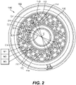
- the circumferential spacing S1 between each adjacent pair of nozzles 110 is wider than the circumferential spacing S2 between each adjacent pair of the nozzles 112, which is in turn greater than the circumferential spacing S3 between each adjacent pair of the nozzles 114.
- the third plurality of fuel nozzles 114 is positioned within an annulus having an inner diameter D1 and an outer diameter D2.
- the second plurality of fuel nozzles 112 is positioned within an annulus having an inner diameter D2 and an outer diameter D3.
- each nozzle 110 services a larger volume V1 of the combustion space than does each nozzle 112, and each nozzle 112 services a larger volume V2 than that (V3) serviced by each nozzle 114.
- V1 is not a reference character in the Figures, but is a conical annular volume bounded between D4 and D3 of Fig. 2 .
- V2 is a conical annular volume bounded by D3 and D2
- V3 is an annular volume bounded by D2 and D1.
- Each of the nozzles 110 in the first plurality of fuel nozzles 100 includes a first effective airflow area A1 defined therethrough (A1 is not shown in the drawings, but is used in the inequality below and is further described below with reference to the Figures).
- Each of the nozzles 112 in the second plurality of fuel nozzles 112 includes a second airflow area A2 defined therethrough (A2 is not shown in the drawings, but is used in the inequality below and is further described below with reference to the Figures).
- a third plurality of fuel nozzles 114 is radially inward from the second plurality of fuel nozzles 112.
- Each of the nozzles 114 in the third plurality of fuel nozzles 114 includes a third airflow area A3 defined therethrough (A3 is not shown in the drawings, but is used in the inequality below and is further described below with reference to the Figures).
- the second airflow area A2 is larger than the third airflow area A3.
- the inequality A1>A2>A3 provides for uniform volumetric flow of air into the combustor, compensating for the different respective volumes V1, V2, V3 serviced by each nozzle 110, 112, 114 for uniform combustion.
- the uniform combustion reduces temperature variation across the combustion volume, which reduces the amount of emission of undesired exhaust products such as NO x .
- each fuel flow through each nozzle 110, 112, 114 can be tailored for its radial position in the combustor 108.
- Each fuel nozzle 110 in the first plurality of fuel nozzles 110 has a first fuel flow area FA1 defined therethrough (FA1 is not shown in the drawings, but is governed by an inequality given below).
- Each fuel nozzle 112 in the second plurality of fuel nozzles 112 has a second fuel flow area FA2 defined therethrough (FA1 is not shown in the drawings, but is governed by an inequality given below).
- Each nozzle 114 in the third plurality of fuel nozzles 114 has a third flow area FA3 defined therethrough (FA1 is not shown in the drawings, but is governed by an inequality given below).
- the fuel flow areas FA1, FA2, FA3 conform to the inequality FA1 > FA2 > FA3.
- the second fuel flow area FA2 is smaller than the first fuel flow area FA1 in proportion to how much smaller the second airflow area A2 is relative to the first air flow area A1.
- the third fuel flow area FA3 is smaller than the second fuel flow area FA2 in proportion to how much smaller the third airflow area A3 is relative to the second air flow area A2.
- This relationship allows for the fuel nozzles 110, 112, 114 to all be set to the same fuel pressure and provide volumetrically even fuel distribution within the combustor 108.
- the first, second, and third fuel flow areas FA1, FA2, FA3 can each be fed by separate respective fuel manifolds M1, M2, M3.
- the first fuel flow area FA1 is pressurized higher than the second fuel flow area FA2, which is pressurized higher than third fuel flow area FA3.
- pressurization of the separate respective fuel manifolds M1, M2, M3 can be proportionate to the respective air flow areas A1, A2, A3 of the first, second, and third pluralities of fuel nozzles 110, 112, 114 for uniform volumetric issuance of fuel into the combustor 108.
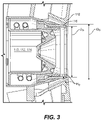
- Each fuel nozzle 110 in the first plurality of fuel nozzles 110 has a channel height H o 1 defined between a prefilmer 116 and an outer air shroud 118, where H o is labeled generically for all the nozzles 110, 112, 114 in Fig. 3 .
- each fuel nozzle 112 in the second plurality of fuel nozzles 112 has a channel height H o 2 defined between a prefilmer and an outer air shroud
- each fuel nozzle 114 in the third plurality of fuel nozzles 114 has a channel height H o 3 defined between a prefilmer and an outer air shroud 118.
- the channel heights can be made to conform to the inequality H o 1 > H o 2 > H o 3 to achieve the difference in the first and second airflow areas A1, A2, and the difference between the second and third airflow areas A2, A3 as explained above with respect to Fig. 2 .
- Each fuel nozzle 110, 112, 114 can have the same outer air shroud diameter D o , in which case the prefilmer diameters D p vary among the three pluralities of fuel nozzles 110, 112, 114, respectively. It is also considered that the prefilmer diameters D p can be the same across all the nozzles 110, 112, 114, and the outer air shroud diameters D o can be varied from one plurality of fuel nozzles to another to achieve the air flow areas A1, A2, A3, or that both the diameters D p and D o can vary. For example, if D p is increased, and H o is kept constant, the effective area of the outer air circuit will be increased. Note that Fig. 3 shows the diameters of D o , D p , which for each given nozzle 110, 112, 114 gives an outer air circuit effective area that is proportional to ⁇ (D o 2 -D p 2 )/4.
- each fuel nozzle 110, 112, 114 has an outer air circuit 120 outboard of its respective fuel circuit 122 comprised of discrete holes 124 distributed circumferentially around the nozzle 110, 112, 114, each individual hole having hole diameter d o .
- the discrete holes 124 of the first plurality of fuel nozzles 110 have a first hole diameter d o 1
- the discrete holes 124 of the second plurality of fuel nozzles 112 have a second hole diameter d o 2
- the discrete holes 124 of the third plurality of fuel nozzles 114 have a third hole diameter d o 3.
- the hole diameters can conform to the inequality d o 1 > d o 2 > d o 3 to achieve the difference in the first and second airflow areas A1, A2, and the difference between the second and third airflow areas A2, A3 as explained above with reference to Fig. 2 .
- each fuel nozzle 110 of the first plurality of fuel nozzles 110 has more discrete holes 124 than those of the second plurality of fuel nozzles 114
- each fuel nozzle 112 of the second plurality of fuel nozzles 112 has more discrete holes 124 than those of the third plurality of fuel nozzles 114 to achieve the difference in the first and second airflow areas A1, A2, and the difference between the second and third airflow areas A2, A3.
- FIG. 7 and 8 another way in which the differing air flow areas A1, A2, and A3 is shown, where one nozzle is shown as representative of each of the different nozzles 110, 112, 114.
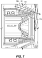
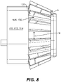
- Each fuel nozzle 110, 112, 114 has an outer air circuit 126, outboard of its respective fuel circuit 122, comprised of vanes 128 with vane passages 130 circumferentially spaced apart by the vanes 128.
- the vane passages 130 have cross-sectional flow areas a o , i.e. where a o is the product of the width w and height h of the individual vane passage 130.
- the vane passages 130 of the first plurality of fuel nozzles 110 have a larger vane passage area a o 1 than that (a o 2) of the second plurality of fuel nozzles 112.
- the vane passages 130 of the second plurality of fuel nozzles 112 have a larger vane passage area (a o 2) larger than that (a o 3) of the third plurality of fuel nozzles 114. This allows for achieving the difference in the first and second airflow areas A1, A2, and the difference between the second and third airflow areas A2, A3 as described above with reference to Fig. 2 .
- the vane passage area a o 1 can have a larger vane passage height h and/or larger vane passage width w than the vane passage area a o 2, and wherein the vane passage area a o 2 has a larger vane passage height h and/or larger vane passage width w than a third vane passage area a o 3 of the third plurality of fuel nozzles 114. It is also contemplated that the thickness of the vanes 128 can be varied among nozzles 110, 112, 114 so the number of vane passages 130 varies to achieve the differences between A1, A2, and A3.
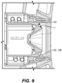
- FIGs. 9 and 10 another way in which the differing air flow areas A1, A2, and A3 is shown, where one nozzle is shown as representative of each of the different nozzles 110, 112, 114.
- Each fuel nozzle 110, 112, 114 has an inner air circuit 132 inboard of its respective fuel circuit 122 comprised of discrete holes 136 distributed circumferentially around the nozzle 110, 112, 114.
- the discrete holes 136 of the first plurality of fuel nozzles 110 have a first hole diameter d i 1
- the discrete holes 136 of the second plurality of fuel nozzles 112 have a second hole diameter d i 2
- the discrete holes 136 of the third plurality of fuel nozzles 114 have a third hole diameter d i 3.
- the hole diameters can conform to the inequality d i 1> d i 2> d i 3 to achieve the difference in the first and second airflow areas A1, A2, and the difference between the second and third airflow areas A2, A3.
- FIG. 11 and 12 another way in which the differing air flow areas A1, A2, and A3 is shown, where one nozzle is shown as representative of each of the different nozzles 110, 112, 114.
- Each fuel nozzle 110, 112, 114 has an inner air circuit 132 (inboard of the fuel circuit 122) comprised of vanes 134 with vane passages 136 circumferentially spaced apart by the vanes 134.
- the vane passages 136 of fuel nozzles 110 have a larger vane passage area a i 1 than that (a i 2) of the second plurality of fuel nozzles 112, and the vane passages of the second plurality of fuel nozzles 112 have a larger vane passage area (a i 2) larger than that (a i 3) of the third plurality of fuel nozzles 114. This can achieve the difference in the first and second airflow areas A1, A2, and the difference between the second and third airflow areas A2, A3.
- the vane passage area a i 1 has a larger vane passage height V H and/or larger vane passage width Vw than the vane passage area a i 2
- the vane passage area a i 2 has a larger vane passage height V H and/or larger vane passage width Vw than a third vane passage area a i 3 of the third plurality of fuel nozzles 114.
- each ring or plurality radially inward from another one of the pluralities of fuel nozzles has a smaller airflow area than whichever one of the plurality of fuel nozzles is immediately radially outward therefrom.
- the various strategies of varying effective area described above with reference to Figs 3-12 can be used in combination with one another without departing from the scope of this disclosure.
Landscapes
- Engineering & Computer Science (AREA)
- Chemical & Material Sciences (AREA)
- Combustion & Propulsion (AREA)
- Mechanical Engineering (AREA)
- General Engineering & Computer Science (AREA)
- Spray-Type Burners (AREA)
Abstract
Description
- This disclosure relates to fuel injection in gas turbine engines, and more particularly to fuel injection in systems with multi-nozzle arrays.
- Fuel and air distribution within a combustor for a gas turbine engine is a significant factor for both temperature profiles within the combustor volume as well as pollutant emissions such as NOx. Multi-point lean direct injection (MLDI) arrays have radial stages of fuel injectors which inject nearly all of the air into the combustor.
- MLDI arrays have provided an advance over previous injection systems in terms of temperature profiles as well as emissions, but there is an ongoing need for further improved fuel injection. This disclosure provides a solution for this need.
- A fuel injection system for a gas turbine engine includes a first plurality of fuel nozzles arrayed in a circular pattern. Each of the nozzles in the first plurality of fuel nozzles includes a first airflow area defined therethrough. A second plurality of fuel nozzles is included radially inward from the first plurality of fuel nozzles. Each of the nozzles in the second plurality of fuel nozzles includes a second airflow area defined therethrough. The first airflow area is larger than the second airflow area.
- A third plurality of fuel nozzles can be radially inward from the second plurality of fuel nozzles. Each of the nozzles in the third plurality of fuel nozzles can include a third airflow area defined therethrough. The second airflow area can be larger than the third airflow area. Each of the first, second, and third pluralities of fuel nozzles can include an equal number of fuel nozzles. At least one additional plurality of fuel nozzles can be included, each radially inward from another one of the pluralities of fuel nozzles, and each having a smaller airflow area than whichever one of the plurality of fuel nozzles is immediately radially outward therefrom.
- Each fuel nozzle in the first plurality of fuel nozzles can have a first fuel flow area defined therethrough. Each fuel nozzle in the second plurality of fuel nozzles can have a second fuel flow area defined therethrough. Each nozzle in the third plurality of fuel nozzles can have a third flow area defined therethrough. The second fuel flow area can be smaller than the first fuel flow area in proportion to how much smaller the second airflow area is relative to the first air flow area. The third fuel flow area can be smaller than the second fuel flow area in proportion to how much smaller the third airflow area is relative to the second air flow area. It is also contemplated that the first, second, and third fuel flow areas can each be fed by separate respective fuel manifolds, wherein the first fuel flow area is pressurized higher than the second fuel flow area, which is pressurized higher than third fuel flow area, wherein pressurization of the separate respective fuel manifolds are proportionate to the respective air flow areas of the first, second, and third pluralities of fuel nozzles.
- The third plurality of fuel nozzles can be positioned within an annulus having an inner diameter D1 and an outer diameter D2. The second plurality of fuel nozzles can be positioned within an annulus having an inner diameter D2 and an outer diameter D3. The first plurality of fuel nozzles can be positioned within an annulus having an inner diameter D3 and an outer diameter D4, wherein D4-D3 = D3-D2 = D2-D1.
- Each fuel nozzle in the first plurality of fuel nozzles can have a channel height defined between a prefilmer and an outer air shroud, Ho1. Each fuel nozzle in the second plurality of fuel nozzles can have a channel height defined between a prefilmer and an outer air shroud, Ho2. Each fuel nozzle in the third plurality of fuel nozzles can have a channel height defined between a prefilmer and an outer air shroud, Ho3, wherein Ho1>Ho2>Ho3 to achieve the difference in the first and second airflow areas, and the difference between the second and third airflow areas. Each fuel nozzle in the first, second, and third pluralities of fuel nozzles can have an equal outer air shroud diameter.
- Each fuel nozzle in the first, second, and third pluralities of fuel nozzles can have an outer air circuit comprised of discrete holes distributed circumferentially around the nozzle. The discrete holes of the first plurality of fuel nozzles can have a first hole diameter do1, the discrete holes of the second plurality of fuel nozzles can have a second hole diameter do2, and the discrete holes of the third plurality of fuel nozzles can have a third hole diameter do3. The hole diameters can conform to the inequality do1>do2>do3 to achieve the difference in the first and second airflow areas, and the difference between the second and third airflow areas. It is also contemplated that it is possible for do1 = do2 = do3, wherein each fuel nozzle of the first plurality of fuel nozzles has more discrete holes than those of the second plurality of fuel nozzles, and wherein each fuel nozzle of the second plurality of fuel nozzles has more discrete holes than those of the third plurality of fuel nozzles to achieve the difference in the first and second airflow areas, and the difference between the second and third airflow areas.
- Each fuel nozzle in the first, second, and third pluralities of fuel nozzles can have an outer air circuit comprised of vanes with vane passages circumferentially spaced apart by the vanes. The vane passages of the first plurality of fuel nozzles can have a larger vane passage area ao1 than that (ao2) of the second plurality of fuel nozzles. The vane passages of the second plurality of fuel nozzles can have a larger vane passage area (ao2) larger than that (ao3) of the third plurality of fuel nozzles. This allows for achieving the difference in the first and second airflow areas, and the difference between the second and third airflow areas. It is also contemplated that the vane passage area ao1 can have a larger vane passage height and/or larger vane passage width than the vane passage area ao2, and wherein the vane passage area ao2 can have a larger vane passage height and/or larger vane passage width than a third vane passage area ao3 of the third plurality of fuel nozzles.
- Each fuel nozzle in the first, second, and third pluralities of fuel nozzles can have an inner air circuit comprised of discrete holes distributed circumferentially around the nozzle. The discrete holes of the first plurality of fuel nozzles can have a first hole diameter di1, the discrete holes of the second plurality of fuel nozzles can have a second hole diameter di2, and the discrete holes of the third plurality of fuel nozzles can have a third hole diameter di3. The hole diameters can conform to the inequality di1> di2> di3 to achieve the difference in the first and second airflow areas, and the difference between the second and third airflow areas. It is also contemplated that the hole diameters can be di1 = di2 = di3, and each fuel nozzle of the first plurality of fuel nozzles can have more discrete holes than those of the second plurality of fuel nozzles, and each fuel nozzle of the second plurality of fuel nozzles can have more discrete holes than those of the third plurality of fuel nozzles to achieve the difference in the first and second airflow areas, and the difference between the second and third airflow areas.
- Each fuel nozzle in the first, second, and third pluralities of fuel nozzles can have an inner air circuit comprised of vanes with vane passages circumferentially spaced apart by the vanes. The vane passages of the first plurality of fuel nozzles can have a larger vane passage area ai1 than that (ai2) of the second plurality of fuel nozzles, and the vane passages of the second plurality of fuel nozzles can have a larger vane passage area (ai2) larger than that (ai3) of the third plurality of fuel nozzles. This can achieve the difference in the first and second airflow areas, and the difference between the second and third airflow areas. It is also contemplated that the vane passage area ai1 can have a larger vane passage height and/or larger vane passage width than the vane passage area ai2, and wherein the vane passage area ai2 can have a larger vane passage height and/or larger vane passage width than a third vane passage area ai3 of the third plurality of fuel nozzles.
- These and other features will become more readily apparent from the following detailed description and the accompanying drawings.
-
-
Fig. 1 is a schematic, cross-sectional perspective view of a portion of a gas turbine engine constructed in accordance with the present disclosure, showing the nozzles for issuing air from the compressor section into the combustor; -
Fig. 2 is a schematic, downstream end elevation view of the combustor ofFig. 1 , showing the arrangement of the nozzles; -
Fig. 3 is a schematic cross-sectional side elevation view of one of the nozzles ofFig. 2 , showing how the outer air circuit can be varied to vary the effective area; -
Figs. 4 ,5 , and6 are schematic cross-sectional side elevation, perspective, and end elevation views, respectively, of another embodiment of nozzle having discrete holes in the outer air circuit; -
Figs. 7 and8 are schematic cross-sectional side elevation and side elevation views showing another embodiment of an outer air circuit with vanes, wherein the outer portions of the nozzle are removed inFig. 8 to show the vanes; -
Figs. 9 and10 are schematic cross-sectional side elevation and downstream end elevation views of another embodiment of nozzle, wherein the discrete holes of the inner air circuit can vary in diameter from one nozzle to another to provide different effective areas for air flow; and -
Figs. 11 and12 are schematic cross-sectional side elevation and downstream end elevation views of another embodiment of nozzle, wherein vane passages in an inner air circuit can vary in dimension from one nozzle to another to provide different effective areas for air flow. - Reference will now be made to the drawings wherein like reference numerals identify similar structural features or aspects of the subject disclosure. For purposes of explanation and illustration, and not limitation, a partial view of an embodiment of a system in accordance with the disclosure is shown in
Fig. 1 and is designated generally byreference character 100. Other embodiments of systems in accordance with the disclosure, or aspects thereof, are provided inFigs. 2-12 , as will be described. The systems and methods described herein can be used to improve combustion uniformity in multi-point lean direct injection (MLDI) combustion systems for gas turbine engines. - The
fuel injection system 100 is part of agas turbine engine 102 that includes acompressor section 104 that feeds compressed gas to acombustor 108, which issues combustion products to aturbine section 106. The compressed air from thecompressor section 104 enters thecombustor 108 through fuel nozzles, specifically, three rings or pluralities offuel nozzles fuel nozzles - With reference now to
Fig. 2 , a first plurality offuel nozzles 110 are arrayed in a circular pattern around the center axis C of theengine 102. A second plurality offuel nozzles 112 are arrayed radially inward from the first plurality offuel nozzles 110. The first airflow area A1 is larger than the second airflow area A2. A1 and A2 are not reference characters in the drawings, but are used in mathematical expressions below and are further described below with reference to the Figures. The circumferential spacing S1 between each adjacent pair ofnozzles 110 is wider than the circumferential spacing S2 between each adjacent pair of thenozzles 112, which is in turn greater than the circumferential spacing S3 between each adjacent pair of thenozzles 114. There are the same number ofnozzles 110 in the outer most first plurality offuel nozzles 110 as there are in the second plurality offuel nozzles 112 as there are in the inner most third plurality offuel nozzles 114. The third plurality offuel nozzles 114 is positioned within an annulus having an inner diameter D1 and an outer diameter D2. The second plurality offuel nozzles 112 is positioned within an annulus having an inner diameter D2 and an outer diameter D3. The first plurality offuel nozzles 110 is positioned within an annulus having an inner diameter D3 and an outer diameter D4, wherein D4-D3 = D3-D2 = D2-D1. Therefore, eachnozzle 110 services a larger volume V1 of the combustion space than does eachnozzle 112, and eachnozzle 112 services a larger volume V2 than that (V3) serviced by eachnozzle 114. V1 is not a reference character in the Figures, but is a conical annular volume bounded between D4 and D3 ofFig. 2 . Similarly, V2 is a conical annular volume bounded by D3 and D2, and V3 is an annular volume bounded by D2 and D1. - Each of the
nozzles 110 in the first plurality offuel nozzles 100 includes a first effective airflow area A1 defined therethrough (A1 is not shown in the drawings, but is used in the inequality below and is further described below with reference to the Figures). Each of thenozzles 112 in the second plurality offuel nozzles 112 includes a second airflow area A2 defined therethrough (A2 is not shown in the drawings, but is used in the inequality below and is further described below with reference to the Figures). A third plurality offuel nozzles 114 is radially inward from the second plurality offuel nozzles 112. Each of thenozzles 114 in the third plurality offuel nozzles 114 includes a third airflow area A3 defined therethrough (A3 is not shown in the drawings, but is used in the inequality below and is further described below with reference to the Figures). The second airflow area A2 is larger than the third airflow area A3. Given that all three pluralities offuel nozzles nozzles nozzle - Similar to airflow, the fuel flow through each
nozzle combustor 108. Eachfuel nozzle 110 in the first plurality offuel nozzles 110 has a first fuel flow area FA1 defined therethrough (FA1 is not shown in the drawings, but is governed by an inequality given below). Eachfuel nozzle 112 in the second plurality offuel nozzles 112 has a second fuel flow area FA2 defined therethrough (FA1 is not shown in the drawings, but is governed by an inequality given below). Eachnozzle 114 in the third plurality offuel nozzles 114 has a third flow area FA3 defined therethrough (FA1 is not shown in the drawings, but is governed by an inequality given below). The fuel flow areas FA1, FA2, FA3 conform to the inequality FA1 > FA2 > FA3. The second fuel flow area FA2 is smaller than the first fuel flow area FA1 in proportion to how much smaller the second airflow area A2 is relative to the first air flow area A1. Similarly, the third fuel flow area FA3 is smaller than the second fuel flow area FA2 in proportion to how much smaller the third airflow area A3 is relative to the second air flow area A2. This relationship allows for thefuel nozzles combustor 108. It is also contemplated that the first, second, and third fuel flow areas FA1, FA2, FA3 can each be fed by separate respective fuel manifolds M1, M2, M3. In this case, the first fuel flow area FA1 is pressurized higher than the second fuel flow area FA2, which is pressurized higher than third fuel flow area FA3. Thus pressurization of the separate respective fuel manifolds M1, M2, M3 can be proportionate to the respective air flow areas A1, A2, A3 of the first, second, and third pluralities offuel nozzles combustor 108. - Referring now to
Fig. 3 , onenozzle nozzles fuel nozzle 110 in the first plurality offuel nozzles 110 has a channel height Ho1 defined between aprefilmer 116 and anouter air shroud 118, where Ho is labeled generically for all thenozzles Fig. 3 . Similarly, eachfuel nozzle 112 in the second plurality offuel nozzles 112 has a channel height Ho2 defined between a prefilmer and an outer air shroud, , and eachfuel nozzle 114 in the third plurality offuel nozzles 114 has a channel height Ho3 defined between a prefilmer and anouter air shroud 118. The channel heights can be made to conform to the inequality Ho1 > Ho2 > Ho3 to achieve the difference in the first and second airflow areas A1, A2, and the difference between the second and third airflow areas A2, A3 as explained above with respect toFig. 2 . Eachfuel nozzle fuel nozzles nozzles Fig. 3 shows the diameters of Do, Dp, which for each givennozzle - With reference now to
Figs. 4 ,5 , and6 , another nozzle is shown as representative of all of thenozzles fuel nozzle respective fuel circuit 122 comprised of discrete holes 124 distributed circumferentially around thenozzle fuel nozzles 110 have a first hole diameter do1, the discrete holes 124 of the second plurality offuel nozzles 112 have a second hole diameter do2, and the discrete holes 124 of the third plurality offuel nozzles 114 have a third hole diameter do3. The hole diameters can conform to the inequality do1 > do2 > do3 to achieve the difference in the first and second airflow areas A1, A2, and the difference between the second and third airflow areas A2, A3 as explained above with reference toFig. 2 . It is also contemplated that it is possible for do1 = do2 = do3, wherein eachfuel nozzle 110 of the first plurality offuel nozzles 110 has more discrete holes 124 than those of the second plurality offuel nozzles 114, and wherein eachfuel nozzle 112 of the second plurality offuel nozzles 112 has more discrete holes 124 than those of the third plurality offuel nozzles 114 to achieve the difference in the first and second airflow areas A1, A2, and the difference between the second and third airflow areas A2, A3. - With reference now to
Figs. 7 and8 , another way in which the differing air flow areas A1, A2, and A3 is shown, where one nozzle is shown as representative of each of thedifferent nozzles fuel nozzle respective fuel circuit 122, comprised ofvanes 128 with vane passages 130 circumferentially spaced apart by thevanes 128. The vane passages 130 have cross-sectional flow areas ao, i.e. where ao is the product of the width w and height h of the individual vane passage 130. The vane passages 130 of the first plurality offuel nozzles 110 have a larger vane passage area ao1 than that (ao2) of the second plurality offuel nozzles 112. The vane passages 130 of the second plurality offuel nozzles 112 have a larger vane passage area (ao2) larger than that (ao3) of the third plurality offuel nozzles 114. This allows for achieving the difference in the first and second airflow areas A1, A2, and the difference between the second and third airflow areas A2, A3 as described above with reference toFig. 2 . It is also contemplated that the vane passage area ao1 can have a larger vane passage height h and/or larger vane passage width w than the vane passage area ao2, and wherein the vane passage area ao2 has a larger vane passage height h and/or larger vane passage width w than a third vane passage area ao3 of the third plurality offuel nozzles 114. It is also contemplated that the thickness of thevanes 128 can be varied amongnozzles - With reference now to
Figs. 9 and10 , another way in which the differing air flow areas A1, A2, and A3 is shown, where one nozzle is shown as representative of each of thedifferent nozzles fuel nozzle inner air circuit 132 inboard of itsrespective fuel circuit 122 comprised ofdiscrete holes 136 distributed circumferentially around thenozzle discrete holes 136 of the first plurality offuel nozzles 110 have a first hole diameter di1, thediscrete holes 136 of the second plurality offuel nozzles 112 have a second hole diameter di2, and thediscrete holes 136 of the third plurality offuel nozzles 114 have a third hole diameter di3. The hole diameters can conform to the inequality di1> di2> di3 to achieve the difference in the first and second airflow areas A1, A2, and the difference between the second and third airflow areas A2, A3. It is also contemplated that the hole diameters can be di1 = di2 = di3, where eachfuel nozzle 110 of the first plurality offuel nozzles 110 has morediscrete holes 136 than those of the second plurality offuel nozzles 112, and wherein eachfuel nozzle 112 of the second plurality offuel nozzles 112 has morediscrete holes 136 than those of the third plurality offuel nozzles 114 to achieve the difference in the first and second airflow areas A1, A2, and the difference between the second and third airflow areas A2, A3. - With reference now to
Figs. 11 and12 , another way in which the differing air flow areas A1, A2, and A3 is shown, where one nozzle is shown as representative of each of thedifferent nozzles fuel nozzle vanes 134 withvane passages 136 circumferentially spaced apart by thevanes 134. Thevane passages 136 offuel nozzles 110 have a larger vane passage area ai1 than that (ai2) of the second plurality offuel nozzles 112, and the vane passages of the second plurality offuel nozzles 112 have a larger vane passage area (ai2) larger than that (ai3) of the third plurality offuel nozzles 114. This can achieve the difference in the first and second airflow areas A1, A2, and the difference between the second and third airflow areas A2, A3. It is also contemplated that the vane passage area ai1 has a larger vane passage height VH and/or larger vane passage width Vw than the vane passage area ai2, and wherein the vane passage area ai2 has a larger vane passage height VH and/or larger vane passage width Vw than a third vane passage area ai3 of the third plurality offuel nozzles 114. It is also possible to change the number ofvane passages 136 in addition to or in lieu of changing the vane passage area ai. - While shown and described herein with three different pluralities of fuel nozzles, 110, 112, 114, those skilled in the art will readily appreciate that any suitable number rings or pluralities of nozzles can be used, including 2, 4, 5, or more. Regardless of how many rings or pluralities of nozzles are used, each ring or plurality radially inward from another one of the pluralities of fuel nozzles has a smaller airflow area than whichever one of the plurality of fuel nozzles is immediately radially outward therefrom. Moreover, those skilled in the art will readily appreciate that the various strategies of varying effective area described above with reference to
Figs 3-12 can be used in combination with one another without departing from the scope of this disclosure. - While the apparatus and methods of the subject disclosure have been shown and described, those skilled in the art will readily appreciate that changes and/or modifications may be made thereto without departing from the scope of the claims.
Claims (15)
- A fuel injection system (100) for a gas turbine engine (102) comprising:a first plurality of fuel nozzles (110) arrayed in a circular pattern, wherein each of the nozzles in the first plurality of fuel nozzles (110) includes a first airflow area defined therethrough;a second plurality of fuel nozzles (112) radially inward from the first plurality of fuel nozzles (110, wherein each of the nozzles in the second plurality of fuel nozzles includes a second airflow area defined therethrough, wherein the first airflow area is larger than the second airflow area.
- The system as recited in claim 1, further comprising a third plurality of fuel nozzles (114) radially inward from the second plurality of fuel nozzles (112), wherein each of the nozzles in the third plurality of fuel nozzles (113) includes a third airflow area defined therethrough, wherein the second airflow area is larger than the third airflow area.
- The system as recited in claim 2, wherein each of the first, second, and third pluralities of fuel nozzles (110, 112, 114) includes an equal number of fuel nozzles.
- The system as recited in claim 2 or claim 3, further comprising at least one additional plurality of fuel nozzles, each radially inward from another one of the pluralities of fuel nozzles, and each having a smaller airflow area than one of the plurality of fuel nozzles that is immediately radially outward therefrom.
- The system as recited in any of claims 2 to 4, wherein each fuel nozzle in the first plurality of fuel nozzles (110) has a first fuel flow area defined therethrough, wherein each fuel nozzle in the second plurality of fuel nozzles (112) has a second fuel flow area defined therethrough, and wherein each nozzle in the third plurality of fuel nozzles (114) has a third flow area defined therethrough.
- The system as recited in claim 5, wherein the second fuel flow area is smaller than the first fuel flow area in proportion to the difference in size between the second airflow area and the first air flow area, and wherein the third fuel flow area is smaller than the second fuel flow area in proportion to how much smaller the third airflow area is relative to the second air flow area, and/or
wherein the first, second, and third fuel flow areas are each fed by separate respective fuel manifolds, wherein the first fuel flow area is pressurized higher than the second fuel flow area, which is pressurized higher than third fuel flow area, wherein pressurization of the separate respective fuel manifolds are proportionate to the respective air flow areas of the first, second, and third pluralities of fuel nozzles. - The system as recited in any of claims 2 to 6,wherein the third plurality of fuel nozzles (114) is positioned within an annulus having an inner diameter D1 and an outer diameter D2,wherein the second plurality of fuel nozzles (112) is positioned within an annulus having an inner diameter D2 and an outer diameter D3, andwherein the first plurality of fuel nozzles (110) is positioned within an annulus having an inner diameter D3 and an outer diameter D4, wherein D4-D3 = D3-D2 = D2-D1.
- The system as recited in any of claims 2 to 7,wherein each fuel nozzle in the first plurality of fuel nozzles (110) has a channel height defined between a prefilmer and an outer air shroud, Ho1,wherein each fuel nozzle in the second plurality of fuel nozzles (112) has a channel height defined between a prefilmer and an outer air shroud, Ho2,wherein each fuel nozzle in the third plurality of fuel nozzles (114) has a channel height defined between a prefilmer and an outer air shroud, Ho3, andwherein Ho1>Ho2>Ho3 to achieve the difference in the first and second airflow areas, and the difference between the second and third airflow areas; and optionallywherein each fuel nozzle in the first, second, and third pluralities of fuel nozzles has an equal outer air shroud diameter.
- The system as recited in any of claims 2 to 8, wherein each fuel nozzle in the first, second, and third pluralities of fuel nozzles (110, 112, 114) has an outer air circuit comprised of discrete holes distributed circumferentially around the nozzle,wherein the discrete holes of the first plurality of fuel nozzles (110) have a first hole diameter do1,wherein the discrete holes of the second plurality of fuel nozzles (112) have a second hole diameter do2,wherein the discrete holes of the third plurality of fuel nozzles (114) have a third hole diameter do3.
- The system as recited in claim 9, wherein do1>do2>do3 to achieve the difference in the first and second airflow areas, and the difference between the second and third airflow areas, and/or
wherein do1 = do2 = do3, and wherein each fuel nozzle of the first plurality of fuel nozzles (110) has more discrete holes than those of the second plurality of fuel nozzles (112), and wherein each fuel nozzle of the second plurality of fuel nozzles (112) has more discrete holes than those of the third plurality of fuel nozzles (114) to achieve the difference in the first and second airflow areas, and the difference between the second and third airflow areas. - The system as recited in any of claims 2 to 10, wherein each fuel nozzle in the first, second, and third pluralities of fuel nozzles (110, 112, 114) has an outer air circuit (126) comprised of vanes (128) with vane passages (130) circumferentially spaced apart by the vanes (128), wherein the vane passages (130) of the first plurality of fuel nozzles (110) have a larger vane passage area ao1 than that (ao2) of the second plurality of fuel nozzles (112), and wherein the vane passages of the second plurality of fuel nozzles (112) have a larger vane passage area (ao2) larger than that (ao3) of the third plurality of fuel nozzles (114), to achieve the difference in the first and second airflow areas, and the difference between the second and third airflow areas, and optionally
wherein the vane passage area ao1 has a larger vane passage height and/or larger vane passage width than the vane passage area ao2, and wherein the vane passage area ao2 has a larger vane passage height and/or larger vane passage width than a third vane passage area ao3 of the third plurality of fuel nozzles (114). - The system as recited in any of claims 2 to 11, wherein each fuel nozzle in the first, second, and third pluralities of fuel nozzles (110, 112, 114) has an inner air circuit (132) comprised of discrete holes (136) distributed circumferentially around the nozzle,wherein the discrete holes (136) of the first plurality of fuel nozzles (110) have a first hole diameter di1,wherein the discrete holes (136) of the second plurality of fuel nozzles (112) have a second hole diameter di2,wherein the discrete holes (136) of the third plurality of fuel nozzles (114) have a third hole diameter di3.
- The system as recited in claim 12, wherein di1> di2> di3 to achieve the difference in the first and second airflow areas, and the difference between the second and third airflow areas, and/or
wherein di1 = di2 = di3, and wherein each fuel nozzle of the first plurality of fuel nozzles (110) has more discrete holes (136) than those of the second plurality of fuel nozzles (112), and wherein each fuel nozzle of the second plurality of fuel nozzles (112) has more discrete holes (136) than those of the third plurality of fuel nozzles (114) to achieve the difference in the first and second airflow areas, and the difference between the second and third airflow areas. - The system as recited in any of claims 2 to 13, wherein each fuel nozzle in the first, second, and third pluralities of fuel nozzles (110, 112, 114) has an inner air circuit comprised of vanes with vane passages circumferentially spaced apart by the vanes, wherein the vane passages of the first plurality of fuel nozzles (110) have a larger vane passage area ai1 than that (ai2) of the second plurality of fuel nozzles (112), and wherein the vane passages of the second plurality of fuel nozzles (112) have a larger vane passage area (ai2) larger than that (ai3) of the third plurality of fuel nozzles (114), to achieve the difference in the first and second airflow areas, and the difference between the second and third airflow areas.
- The system as recited in claim 14, wherein the vane passage area ai1 has a larger vane passage height and/or larger vane passage width than the vane passage area ai2, and wherein the vane passage area ai2 has a larger vane passage height and/or larger vane passage width than a third vane passage area ai3 of the third plurality of fuel nozzles.
Applications Claiming Priority (1)
| Application Number | Priority Date | Filing Date | Title |
|---|---|---|---|
| US17/356,825 US20220412264A1 (en) | 2021-06-24 | 2021-06-24 | Radial equilibrated combustion nozzle array |
Publications (2)
| Publication Number | Publication Date |
|---|---|
| EP4108990A1 true EP4108990A1 (en) | 2022-12-28 |
| EP4108990B1 EP4108990B1 (en) | 2025-11-12 |
Family
ID=82258204
Family Applications (1)
| Application Number | Title | Priority Date | Filing Date |
|---|---|---|---|
| EP22180741.5A Active EP4108990B1 (en) | 2021-06-24 | 2022-06-23 | Radial equilibrated combustion nozzle array |
Country Status (2)
| Country | Link |
|---|---|
| US (1) | US20220412264A1 (en) |
| EP (1) | EP4108990B1 (en) |
Citations (5)
| Publication number | Priority date | Publication date | Assignee | Title |
|---|---|---|---|---|
| JP2011058775A (en) * | 2009-09-14 | 2011-03-24 | Hitachi Ltd | Gas turbine combustor |
| US20120094239A1 (en) * | 2007-04-26 | 2012-04-19 | Hitachi, Ltd. | Combustor and a fuel supply method for the combustor |
| US20150361896A1 (en) * | 2011-11-03 | 2015-12-17 | Delavan Inc | Injectors for multipoint injection |
| US20160245187A1 (en) * | 2013-10-04 | 2016-08-25 | United Technologies Corporaton | Automatic control of turbine blade temperature during gas turbine engine operation |
| US20190309950A1 (en) * | 2018-04-10 | 2019-10-10 | Delavan, Inc. | Fuel injectors having air sealing structures |
Family Cites Families (6)
| Publication number | Priority date | Publication date | Assignee | Title |
|---|---|---|---|---|
| US8146365B2 (en) * | 2007-06-14 | 2012-04-03 | Pratt & Whitney Canada Corp. | Fuel nozzle providing shaped fuel spray |
| JP5103454B2 (en) * | 2009-09-30 | 2012-12-19 | 株式会社日立製作所 | Combustor |
| GB0920094D0 (en) * | 2009-11-17 | 2009-12-30 | Alstom Technology Ltd | Reheat combustor for a gas turbine engine |
| KR102063169B1 (en) * | 2017-07-04 | 2020-01-07 | 두산중공업 주식회사 | Fuel nozzle assembly and combustor and gas turbine having the same |
| KR102066042B1 (en) * | 2017-10-31 | 2020-01-14 | 두산중공업 주식회사 | Combustor and gas turbine including the same |
| US11118785B2 (en) * | 2018-10-26 | 2021-09-14 | Delavan Inc. | Fuel injectors for exhaust heaters |
-
2021
- 2021-06-24 US US17/356,825 patent/US20220412264A1/en not_active Abandoned
-
2022
- 2022-06-23 EP EP22180741.5A patent/EP4108990B1/en active Active
Patent Citations (5)
| Publication number | Priority date | Publication date | Assignee | Title |
|---|---|---|---|---|
| US20120094239A1 (en) * | 2007-04-26 | 2012-04-19 | Hitachi, Ltd. | Combustor and a fuel supply method for the combustor |
| JP2011058775A (en) * | 2009-09-14 | 2011-03-24 | Hitachi Ltd | Gas turbine combustor |
| US20150361896A1 (en) * | 2011-11-03 | 2015-12-17 | Delavan Inc | Injectors for multipoint injection |
| US20160245187A1 (en) * | 2013-10-04 | 2016-08-25 | United Technologies Corporaton | Automatic control of turbine blade temperature during gas turbine engine operation |
| US20190309950A1 (en) * | 2018-04-10 | 2019-10-10 | Delavan, Inc. | Fuel injectors having air sealing structures |
Also Published As
| Publication number | Publication date |
|---|---|
| US20220412264A1 (en) | 2022-12-29 |
| EP4108990B1 (en) | 2025-11-12 |
Similar Documents
| Publication | Publication Date | Title |
|---|---|---|
| US9765973B2 (en) | System and method for tube level air flow conditioning | |
| US5592820A (en) | Gas turbine diffuser | |
| EP3671039B1 (en) | Multipoint fuel injection system with heat shield | |
| US4864827A (en) | Combustor | |
| JP5795716B2 (en) | Gas turbine engine steam injection manifold | |
| EP3382280B1 (en) | Fuel injectors for multipoint arrays | |
| US8387395B2 (en) | Annular combustion chamber for a turbomachine | |
| US6070412A (en) | Turbomachine combustion chamber with inner and outer injector rows | |
| JP3011524B2 (en) | Combustor liner | |
| US5335501A (en) | Flow spreading diffuser | |
| US6651439B2 (en) | Methods and apparatus for supplying air to turbine engine combustors | |
| US5632141A (en) | Diffuser with controlled diffused air discharge | |
| CA2476747A1 (en) | Methods and apparatus for cooling turbine engine combustor exit temperatures | |
| US8215118B2 (en) | Optimizing the angular positioning of a turbine nozzle at the outlet from a turbomachine combustion chamber | |
| US20100011773A1 (en) | Combustor liner and method of fabricating same | |
| US20170298827A1 (en) | Segmented Annular Combustion System | |
| US20090100840A1 (en) | Combustion chamber with optimised dilution and turbomachine provided with same | |
| US20160047316A1 (en) | Systems and apparatus relating to gas turbine combustors | |
| US7000400B2 (en) | Temperature variance reduction using variable penetration dilution jets | |
| US11674687B2 (en) | Fuel manifolds | |
| US11713717B2 (en) | Sectional fuel manifolds | |
| JP5485532B2 (en) | Combustion chamber wall with optimized dilution and cooling and combustion chamber and turbomachine with the same | |
| US4720971A (en) | Method for distributing augmentor fuel | |
| US10876477B2 (en) | Nozzles with internal manifolding | |
| EP4108990B1 (en) | Radial equilibrated combustion nozzle array |
Legal Events
| Date | Code | Title | Description |
|---|---|---|---|
| PUAI | Public reference made under article 153(3) epc to a published international application that has entered the european phase |
Free format text: ORIGINAL CODE: 0009012 |
|
| STAA | Information on the status of an ep patent application or granted ep patent |
Free format text: STATUS: THE APPLICATION HAS BEEN PUBLISHED |
|
| AK | Designated contracting states |
Kind code of ref document: A1 Designated state(s): AL AT BE BG CH CY CZ DE DK EE ES FI FR GB GR HR HU IE IS IT LI LT LU LV MC MK MT NL NO PL PT RO RS SE SI SK SM TR |
|
| STAA | Information on the status of an ep patent application or granted ep patent |
Free format text: STATUS: REQUEST FOR EXAMINATION WAS MADE |
|
| 17P | Request for examination filed |
Effective date: 20230627 |
|
| RBV | Designated contracting states (corrected) |
Designated state(s): AL AT BE BG CH CY CZ DE DK EE ES FI FR GB GR HR HU IE IS IT LI LT LU LV MC MK MT NL NO PL PT RO RS SE SI SK SM TR |
|
| P01 | Opt-out of the competence of the unified patent court (upc) registered |
Effective date: 20230922 |
|
| STAA | Information on the status of an ep patent application or granted ep patent |
Free format text: STATUS: EXAMINATION IS IN PROGRESS |
|
| 17Q | First examination report despatched |
Effective date: 20240306 |
|
| GRAP | Despatch of communication of intention to grant a patent |
Free format text: ORIGINAL CODE: EPIDOSNIGR1 |
|
| STAA | Information on the status of an ep patent application or granted ep patent |
Free format text: STATUS: GRANT OF PATENT IS INTENDED |
|
| INTG | Intention to grant announced |
Effective date: 20250604 |
|
| RIN1 | Information on inventor provided before grant (corrected) |
Inventor name: PROCIW, LEV A. Inventor name: ZINK, GREGORY A. Inventor name: RYON, JASON |
|
| GRAS | Grant fee paid |
Free format text: ORIGINAL CODE: EPIDOSNIGR3 |
|
| GRAA | (expected) grant |
Free format text: ORIGINAL CODE: 0009210 |
|
| STAA | Information on the status of an ep patent application or granted ep patent |
Free format text: STATUS: THE PATENT HAS BEEN GRANTED |
|
| AK | Designated contracting states |
Kind code of ref document: B1 Designated state(s): AL AT BE BG CH CY CZ DE DK EE ES FI FR GB GR HR HU IE IS IT LI LT LU LV MC MK MT NL NO PL PT RO RS SE SI SK SM TR |
|
| REG | Reference to a national code |
Ref country code: CH Ref legal event code: F10 Free format text: ST27 STATUS EVENT CODE: U-0-0-F10-F00 (AS PROVIDED BY THE NATIONAL OFFICE) Effective date: 20251112 Ref country code: GB Ref legal event code: FG4D |
|
| REG | Reference to a national code |
Ref country code: IE Ref legal event code: FG4D |
|
| REG | Reference to a national code |
Ref country code: DE Ref legal event code: R096 Ref document number: 602022024763 Country of ref document: DE |
|
| REG | Reference to a national code |
Ref country code: NL Ref legal event code: MP Effective date: 20251112 |
|
| PG25 | Lapsed in a contracting state [announced via postgrant information from national office to epo] |
Ref country code: ES Free format text: LAPSE BECAUSE OF FAILURE TO SUBMIT A TRANSLATION OF THE DESCRIPTION OR TO PAY THE FEE WITHIN THE PRESCRIBED TIME-LIMIT Effective date: 20251112 |
|
| REG | Reference to a national code |
Ref country code: LT Ref legal event code: MG9D |
|
| PG25 | Lapsed in a contracting state [announced via postgrant information from national office to epo] |
Ref country code: NO Free format text: LAPSE BECAUSE OF FAILURE TO SUBMIT A TRANSLATION OF THE DESCRIPTION OR TO PAY THE FEE WITHIN THE PRESCRIBED TIME-LIMIT Effective date: 20260212 |
|
| PG25 | Lapsed in a contracting state [announced via postgrant information from national office to epo] |
Ref country code: FI Free format text: LAPSE BECAUSE OF FAILURE TO SUBMIT A TRANSLATION OF THE DESCRIPTION OR TO PAY THE FEE WITHIN THE PRESCRIBED TIME-LIMIT Effective date: 20251112 Ref country code: HR Free format text: LAPSE BECAUSE OF FAILURE TO SUBMIT A TRANSLATION OF THE DESCRIPTION OR TO PAY THE FEE WITHIN THE PRESCRIBED TIME-LIMIT Effective date: 20251112 Ref country code: AT Free format text: LAPSE BECAUSE OF FAILURE TO SUBMIT A TRANSLATION OF THE DESCRIPTION OR TO PAY THE FEE WITHIN THE PRESCRIBED TIME-LIMIT Effective date: 20251112 |
|
| REG | Reference to a national code |
Ref country code: AT Ref legal event code: MK05 Ref document number: 1857006 Country of ref document: AT Kind code of ref document: T Effective date: 20251112 |
|
| PG25 | Lapsed in a contracting state [announced via postgrant information from national office to epo] |
Ref country code: NL Free format text: LAPSE BECAUSE OF FAILURE TO SUBMIT A TRANSLATION OF THE DESCRIPTION OR TO PAY THE FEE WITHIN THE PRESCRIBED TIME-LIMIT Effective date: 20251112 |
|
| PG25 | Lapsed in a contracting state [announced via postgrant information from national office to epo] |
Ref country code: RS Free format text: LAPSE BECAUSE OF FAILURE TO SUBMIT A TRANSLATION OF THE DESCRIPTION OR TO PAY THE FEE WITHIN THE PRESCRIBED TIME-LIMIT Effective date: 20260212 |
|
| PG25 | Lapsed in a contracting state [announced via postgrant information from national office to epo] |
Ref country code: IS Free format text: LAPSE BECAUSE OF FAILURE TO SUBMIT A TRANSLATION OF THE DESCRIPTION OR TO PAY THE FEE WITHIN THE PRESCRIBED TIME-LIMIT Effective date: 20260312 |
|
| PG25 | Lapsed in a contracting state [announced via postgrant information from national office to epo] |
Ref country code: PT Free format text: LAPSE BECAUSE OF FAILURE TO SUBMIT A TRANSLATION OF THE DESCRIPTION OR TO PAY THE FEE WITHIN THE PRESCRIBED TIME-LIMIT Effective date: 20260312 |
|
| PG25 | Lapsed in a contracting state [announced via postgrant information from national office to epo] |
Ref country code: PL Free format text: LAPSE BECAUSE OF FAILURE TO SUBMIT A TRANSLATION OF THE DESCRIPTION OR TO PAY THE FEE WITHIN THE PRESCRIBED TIME-LIMIT Effective date: 20251112 |
|
| PG25 | Lapsed in a contracting state [announced via postgrant information from national office to epo] |
Ref country code: LV Free format text: LAPSE BECAUSE OF FAILURE TO SUBMIT A TRANSLATION OF THE DESCRIPTION OR TO PAY THE FEE WITHIN THE PRESCRIBED TIME-LIMIT Effective date: 20251112 |
|
| PG25 | Lapsed in a contracting state [announced via postgrant information from national office to epo] |
Ref country code: BG Free format text: LAPSE BECAUSE OF FAILURE TO SUBMIT A TRANSLATION OF THE DESCRIPTION OR TO PAY THE FEE WITHIN THE PRESCRIBED TIME-LIMIT Effective date: 20251112 |
|
| PG25 | Lapsed in a contracting state [announced via postgrant information from national office to epo] |
Ref country code: LT Free format text: LAPSE BECAUSE OF FAILURE TO SUBMIT A TRANSLATION OF THE DESCRIPTION OR TO PAY THE FEE WITHIN THE PRESCRIBED TIME-LIMIT Effective date: 20251112 |
|
| PG25 | Lapsed in a contracting state [announced via postgrant information from national office to epo] |
Ref country code: SM Free format text: LAPSE BECAUSE OF FAILURE TO SUBMIT A TRANSLATION OF THE DESCRIPTION OR TO PAY THE FEE WITHIN THE PRESCRIBED TIME-LIMIT Effective date: 20251112 |
|
| PG25 | Lapsed in a contracting state [announced via postgrant information from national office to epo] |
Ref country code: DK Free format text: LAPSE BECAUSE OF FAILURE TO SUBMIT A TRANSLATION OF THE DESCRIPTION OR TO PAY THE FEE WITHIN THE PRESCRIBED TIME-LIMIT Effective date: 20251112 |
|
| PG25 | Lapsed in a contracting state [announced via postgrant information from national office to epo] |
Ref country code: IT Free format text: LAPSE BECAUSE OF FAILURE TO SUBMIT A TRANSLATION OF THE DESCRIPTION OR TO PAY THE FEE WITHIN THE PRESCRIBED TIME-LIMIT Effective date: 20251112 |
|
| PGFP | Annual fee paid to national office [announced via postgrant information from national office to epo] |
Ref country code: DE Payment date: 20260520 Year of fee payment: 5 |
|
| PG25 | Lapsed in a contracting state [announced via postgrant information from national office to epo] |
Ref country code: EE Free format text: LAPSE BECAUSE OF FAILURE TO SUBMIT A TRANSLATION OF THE DESCRIPTION OR TO PAY THE FEE WITHIN THE PRESCRIBED TIME-LIMIT Effective date: 20251112 |
|
| PG25 | Lapsed in a contracting state [announced via postgrant information from national office to epo] |
Ref country code: CZ Free format text: LAPSE BECAUSE OF FAILURE TO SUBMIT A TRANSLATION OF THE DESCRIPTION OR TO PAY THE FEE WITHIN THE PRESCRIBED TIME-LIMIT Effective date: 20251112 |
|
| PG25 | Lapsed in a contracting state [announced via postgrant information from national office to epo] |
Ref country code: SK Free format text: LAPSE BECAUSE OF FAILURE TO SUBMIT A TRANSLATION OF THE DESCRIPTION OR TO PAY THE FEE WITHIN THE PRESCRIBED TIME-LIMIT Effective date: 20251112 |
|
| PG25 | Lapsed in a contracting state [announced via postgrant information from national office to epo] |
Ref country code: SE Free format text: LAPSE BECAUSE OF FAILURE TO SUBMIT A TRANSLATION OF THE DESCRIPTION OR TO PAY THE FEE WITHIN THE PRESCRIBED TIME-LIMIT Effective date: 20251112 |