EP4108859A1 - Torvorrichtung - Google Patents
Torvorrichtung Download PDFInfo
- Publication number
- EP4108859A1 EP4108859A1 EP20920152.4A EP20920152A EP4108859A1 EP 4108859 A1 EP4108859 A1 EP 4108859A1 EP 20920152 A EP20920152 A EP 20920152A EP 4108859 A1 EP4108859 A1 EP 4108859A1
- Authority
- EP
- European Patent Office
- Prior art keywords
- user
- light
- gate apparatus
- gate
- baggage
- Prior art date
- Legal status (The legal status is an assumption and is not a legal conclusion. Google has not performed a legal analysis and makes no representation as to the accuracy of the status listed.)
- Pending
Links
Images


Classifications
-
- G—PHYSICS
- G06—COMPUTING; CALCULATING OR COUNTING
- G06F—ELECTRIC DIGITAL DATA PROCESSING
- G06F21/00—Security arrangements for protecting computers, components thereof, programs or data against unauthorised activity
- G06F21/30—Authentication, i.e. establishing the identity or authorisation of security principals
- G06F21/31—User authentication
- G06F21/32—User authentication using biometric data, e.g. fingerprints, iris scans or voiceprints
-
- G—PHYSICS
- G03—PHOTOGRAPHY; CINEMATOGRAPHY; ANALOGOUS TECHNIQUES USING WAVES OTHER THAN OPTICAL WAVES; ELECTROGRAPHY; HOLOGRAPHY
- G03B—APPARATUS OR ARRANGEMENTS FOR TAKING PHOTOGRAPHS OR FOR PROJECTING OR VIEWING THEM; APPARATUS OR ARRANGEMENTS EMPLOYING ANALOGOUS TECHNIQUES USING WAVES OTHER THAN OPTICAL WAVES; ACCESSORIES THEREFOR
- G03B15/00—Special procedures for taking photographs; Apparatus therefor
- G03B15/02—Illuminating scene
- G03B15/06—Special arrangements of screening, diffusing, or reflecting devices, e.g. in studio
- G03B15/07—Arrangements of lamps in studios
-
- G—PHYSICS
- G06—COMPUTING; CALCULATING OR COUNTING
- G06V—IMAGE OR VIDEO RECOGNITION OR UNDERSTANDING
- G06V40/00—Recognition of biometric, human-related or animal-related patterns in image or video data
- G06V40/10—Human or animal bodies, e.g. vehicle occupants or pedestrians; Body parts, e.g. hands
- G06V40/12—Fingerprints or palmprints
-
- G—PHYSICS
- G07—CHECKING-DEVICES
- G07C—TIME OR ATTENDANCE REGISTERS; REGISTERING OR INDICATING THE WORKING OF MACHINES; GENERATING RANDOM NUMBERS; VOTING OR LOTTERY APPARATUS; ARRANGEMENTS, SYSTEMS OR APPARATUS FOR CHECKING NOT PROVIDED FOR ELSEWHERE
- G07C9/00—Individual registration on entry or exit
- G07C9/10—Movable barriers with registering means
-
- G—PHYSICS
- G07—CHECKING-DEVICES
- G07C—TIME OR ATTENDANCE REGISTERS; REGISTERING OR INDICATING THE WORKING OF MACHINES; GENERATING RANDOM NUMBERS; VOTING OR LOTTERY APPARATUS; ARRANGEMENTS, SYSTEMS OR APPARATUS FOR CHECKING NOT PROVIDED FOR ELSEWHERE
- G07C9/00—Individual registration on entry or exit
- G07C9/20—Individual registration on entry or exit involving the use of a pass
- G07C9/22—Individual registration on entry or exit involving the use of a pass in combination with an identity check of the pass holder
- G07C9/25—Individual registration on entry or exit involving the use of a pass in combination with an identity check of the pass holder using biometric data, e.g. fingerprints, iris scans or voice recognition
- G07C9/257—Individual registration on entry or exit involving the use of a pass in combination with an identity check of the pass holder using biometric data, e.g. fingerprints, iris scans or voice recognition electronically
-
- G—PHYSICS
- G07—CHECKING-DEVICES
- G07C—TIME OR ATTENDANCE REGISTERS; REGISTERING OR INDICATING THE WORKING OF MACHINES; GENERATING RANDOM NUMBERS; VOTING OR LOTTERY APPARATUS; ARRANGEMENTS, SYSTEMS OR APPARATUS FOR CHECKING NOT PROVIDED FOR ELSEWHERE
- G07C9/00—Individual registration on entry or exit
- G07C9/00174—Electronically operated locks; Circuits therefor; Nonmechanical keys therefor, e.g. passive or active electrical keys or other data carriers without mechanical keys
- G07C9/00309—Electronically operated locks; Circuits therefor; Nonmechanical keys therefor, e.g. passive or active electrical keys or other data carriers without mechanical keys operated with bidirectional data transmission between data carrier and locks
-
- G—PHYSICS
- G07—CHECKING-DEVICES
- G07C—TIME OR ATTENDANCE REGISTERS; REGISTERING OR INDICATING THE WORKING OF MACHINES; GENERATING RANDOM NUMBERS; VOTING OR LOTTERY APPARATUS; ARRANGEMENTS, SYSTEMS OR APPARATUS FOR CHECKING NOT PROVIDED FOR ELSEWHERE
- G07C9/00—Individual registration on entry or exit
- G07C9/00174—Electronically operated locks; Circuits therefor; Nonmechanical keys therefor, e.g. passive or active electrical keys or other data carriers without mechanical keys
- G07C9/00563—Electronically operated locks; Circuits therefor; Nonmechanical keys therefor, e.g. passive or active electrical keys or other data carriers without mechanical keys using personal physical data of the operator, e.g. finger prints, retinal images, voicepatterns
-
- G—PHYSICS
- G07—CHECKING-DEVICES
- G07C—TIME OR ATTENDANCE REGISTERS; REGISTERING OR INDICATING THE WORKING OF MACHINES; GENERATING RANDOM NUMBERS; VOTING OR LOTTERY APPARATUS; ARRANGEMENTS, SYSTEMS OR APPARATUS FOR CHECKING NOT PROVIDED FOR ELSEWHERE
- G07C9/00—Individual registration on entry or exit
- G07C9/00174—Electronically operated locks; Circuits therefor; Nonmechanical keys therefor, e.g. passive or active electrical keys or other data carriers without mechanical keys
- G07C9/00571—Electronically operated locks; Circuits therefor; Nonmechanical keys therefor, e.g. passive or active electrical keys or other data carriers without mechanical keys operated by interacting with a central unit
-
- G—PHYSICS
- G07—CHECKING-DEVICES
- G07C—TIME OR ATTENDANCE REGISTERS; REGISTERING OR INDICATING THE WORKING OF MACHINES; GENERATING RANDOM NUMBERS; VOTING OR LOTTERY APPARATUS; ARRANGEMENTS, SYSTEMS OR APPARATUS FOR CHECKING NOT PROVIDED FOR ELSEWHERE
- G07C9/00—Individual registration on entry or exit
- G07C9/10—Movable barriers with registering means
- G07C9/15—Movable barriers with registering means with arrangements to prevent the passage of more than one individual at a time
-
- G—PHYSICS
- G07—CHECKING-DEVICES
- G07C—TIME OR ATTENDANCE REGISTERS; REGISTERING OR INDICATING THE WORKING OF MACHINES; GENERATING RANDOM NUMBERS; VOTING OR LOTTERY APPARATUS; ARRANGEMENTS, SYSTEMS OR APPARATUS FOR CHECKING NOT PROVIDED FOR ELSEWHERE
- G07C9/00—Individual registration on entry or exit
- G07C9/20—Individual registration on entry or exit involving the use of a pass
- G07C9/27—Individual registration on entry or exit involving the use of a pass with central registration
Definitions
- the present invention relates to a gate apparatus.
- Face authentication is beginning to be used in various procedures at airports and other places, such as the gate apparatus disclosed in the above NPL 1.
- an image whose brightness varies depending on time of day when a user is photographed is not suitable for authentication purposes.
- an outline of an example embodiment will be described.
- various components are denoted by reference characters for the sake of convenience. That is, the following reference characters are used as examples to facilitate the understanding of the present invention. Thus, the description of the outline is not intended to impose any limitations.
- an individual block illustrated in the drawings represents a configuration of a functional unit, not a hardware unit.
- An individual connection line between blocks in the drawings signifies both one-way and two-way directions.
- An arrow schematically illustrates a principal signal (data) flow and does not exclude bidirectionality.
- elements that can be described in a like way will be denoted by a like reference character, and redundant description thereof will be omitted as needed.
- the first light 102 is installed to illuminate the user.
- the first light 102 is installed in the ceiling portion of the gate apparatus 100.
- This ceiling portion for example, shades light from outside and creates a suitable environment for acquiring biological information (for example, face image, iris image) of the user regardless of a time of day or other factors. As a result, biological information suitable for authentication applications is obtained.
- the server apparatus 20 is an apparatus that realizes the emigration and immigration examination with the above gate apparatus 10.
- the server apparatus 20 stores information about users who can use the gate apparatus 10 (the information will hereinafter be referred to as gate user information).
- the gate apparatus 10 When a user stands in front of a gate apparatus 10, the user places his or her finger on a scanner in accordance with an instruction given by the gate apparatus 10.
- the gate apparatus 10 acquires a fingerprint image of the user and transmits an examination request including the acquired fingerprint image to the server apparatus 20.
- the server apparatus 20 sets the examination result to "emigration and immigration not permitted".
- the server apparatus 20 transmits the examination result to the gate apparatus 10 that has transmitted the examination request.
- the gate apparatus 10 determines whether the user in front of the gate apparatus 10 possesses a correct passport (his or her own passport). Specifically, the gate apparatus 10 instructs the user to open and place his or her passport on a scanner. The gate apparatus 10 reads out a face image or the like from an IC (Integrated Circuit) chip in the passport by using a card reader function of the scanner. The gate apparatus 10 acquires a face image of the user by using a camera device. The gate apparatus 10 generates feature values (hereinafter, face feature values) from each of the two face images and determines whether the two sets of feature values substantially match. That is, the gate apparatus 10 performs 1-to-1 matching by using the face feature values obtained by capturing an image of the user in front of the gate apparatus 10 and the face feature values obtained from the IC chip in the passport.
- face feature values hereinafter, face feature values
- an officer in charge at a passport center may enter a fingerprint image in the server apparatus 20.
- an officer in charge operates a fingerprint scanner to acquire a fingerprint image of a user.
- the officer in charge operates a terminal (a computer installed at the passport center) to transmit the acquired fingerprint image to the server apparatus 20.
- the above read data may be entered to the server apparatus 20 via an external storage device, such as a USB (Universal Serial Bus) memory.
- USB Universal Serial Bus
- the examination unit 203 is means for processing examination requests transmitted by the gate apparatuses 10. Specifically, the examination unit 203 sets a fingerprint image (biological information) included in an examination request as the matching target fingerprint image and performs matching processing between this fingerprint image and the fingerprint images registered in the registered user database.
- a fingerprint image biological information
- the examination unit 203 sets a fingerprint image extracted from an examination request as the matching target fingerprint image and performs 1-to-N matching between this fingerprint image and the plurality of fingerprint images registered in the registered user database.
- the examination unit 203 calculates a score (similarity) between the fingerprint image as the matching target fingerprint image and each of the plurality of fingerprint images registered.
- the examination unit 203 extracts feature points (edge points, branch points) from each of the matching target fingerprint image and the registered fingerprint images.
- the examination unit 203 calculates a score indicating a similarity between two fingerprint images, based on the extracted feature points, etc. Specifically, the examination unit 203 matches the core area of one fingerprint image (the center area of one fingerprint) with the core area of another fingerprint image (the center area of another fingerprint) and calculates the above score, for example, based on the locations of and the number of feature points seen from each core area and the number of core lines present between feature points. A higher score represents a higher similarity between two fingerprint images.
- Fig. 5 is a diagram illustrating an example of the exterior of a gate apparatus 10 according to the first example embodiment.
- the individual gate apparatus 10 is an apparatus that automatically performs the emigration and immigration examination for users.
- the lower light 405 is embedded into the main body of the gate apparatus 10.
- the "main body” of the gate apparatus 10 is a structure that forms the core of the gate apparatus 10. This main body is into contact with the floor, and a gate 408 and the supporting portion 406 are attached to the main body.
- the gate apparatus 10 keeps the gate 408 closed and displays a predetermined message or the like on the display 401. For example, the gate apparatus 10 displays a message requesting the user to go to a staffed examination booth or to operate the gate apparatus 10 for the automatic examination again.
- the gate apparatus 10 When operating the gate apparatus 10, the user places his or her baggage on a top board area 431 or a side area 432 of the baggage placement area 430.
- the gate apparatus 10 detects whether there is an object on the top board area 431 or the side area 432.
- the gate apparatus 10 detects an object placed on the top board area 431 by using means such as a weight sensor or a pressure sensor.
- the gate apparatus 10 detects an object placed on the side area 432 by using a distance sensor using infrared light or by analyzing an image obtained from a camera.
- one of the conditions for the gate apparatus 10 to open the gate 408 is that the baggage detection flag has been cleared to "0". Even when the user does not notice the display or sound alerting the user about his or her left-behind baggage, since the gate 408 remains closed, the user is prevented from proceeding to the next procedure without his or her baggage.
- processor 311, the memory 312, and the communication interface 313 are equivalent to those of the server apparatus 20 described with reference to Fig. 4 , detailed description thereof will be omitted.
- the display 401 is a device (for example, a liquid crystal monitor or the like) for outputting information.
- the upper light 404 is a light source installed to emit light to the user from above the user.
- the lower light 405 is a light source installed to emit light to the user from below the user.
- the luminance of the upper light 404 and the luminance of the lower light 405 are variable. Since the luminance of the upper light 404 and the luminance of the lower light 405 are variable, the illuminance of the light emitted to the user varies. That is, since the luminance of the upper light 404 and the luminance of the lower light 405 are varied, the brightness of the user seen from the camera device 403 varies.
- Any light source of which luminance is variable may be used as each of the upper light 404 and the lower light 405.
- an LED Light Emitting Diode
- the luminance can be changed by controlling the current flowing through the LED.
- the gate 408 shifts from its standby closed state that blocks passage of the user to its open state that allows passage of the user.
- the mechanism of the gate 408 is not limited to any particular mechanism.
- the gate 408 is a flap gate that opens and closes a flap installed on one side or flaps installed on both sides of the passage or is a turnstile gate that rotate three bars.
- the object detector 409 is a device for detecting an object placed in the baggage placement area 430. As described above, a weight sensor, a distance sensor, or the like may be used as the object detector 409.
- the functions of the gate apparatus 10 are realized by various kinds of processing modules.
- the processing modules are realized by, for example, causing the processor 311 to execute a program stored in the memory 312.
- Fig. 9 is a diagram illustrating an example of a processing configuration (processing modules) of the individual gate apparatus 10 according to the first example embodiment.
- the gate apparatus 10 includes a communication control unit 301, a fingerprint image acquisition unit 302, an examination request unit 303, a face image acquisition unit 304, a passport possession determination unit 305, a baggage detection unit 306, a left-behind baggage alert unit 307, a gate control unit 308, and a storage unit 309.
- the communication control unit 301 is means for controlling communication with other apparatuses. Specifically, the communication control unit 301 receives data (packets) from the server apparatus 20. In addition, the communication control unit 301 transmits data to the server apparatus 20.
- the fingerprint image acquisition unit 302 is means for acquiring a fingerprint image of a user standing in front of the gate apparatus 10.
- the fingerprint image acquisition unit 302 acquires a fingerprint image of a user by controlling the scanner 402.
- the fingerprint image acquisition unit 302 gives the acquired fingerprint image to the examination request unit 303.
- the examination request unit 303 is means for requesting the server apparatus 20 to perform the emigration and immigration examination on the examination target user (the user standing in front of the gate apparatus 10). Specifically, the examination request unit 303 generates an examination request including the acquired fingerprint image (biological information) and transmits the generated examination request to the server apparatus 20 via the communication control unit 301.
- the examination request unit 303 generates an examination request including an identifier of this gate apparatus 10 (hereinafter referred to as a gate identifier), a fingerprint image, etc. (see Fig. 10 ).
- a gate identifier an identifier of this gate apparatus 10
- a fingerprint image etc.
- a MAC (Media Access Control) address or an IP (Internet Protocol) address of the gate apparatus 10 may be used as the gate identifier.
- the face image acquisition unit 304 is means for acquiring a face image (biological information) of the user standing in front of the gate apparatus 10. For example, the face image acquisition unit 304 acquires a face image of the user by controlling the camera device 403. The face image acquisition unit 304 gives the acquired face image to the passport possession determination unit 305.
- the gate apparatus 10 controls the luminance of the upper light 404 and the luminance of the lower light 405.
- the face image acquisition unit 304 controls the luminance of the upper light 404 and the luminance of the lower light 405 such that the face of the user is illuminated with light with substantially uniform illuminance when an image of the face of the user is captured.
- the face image acquisition unit 304 may control the luminance of only one of the upper light 404 and the lower light 405.
- the face image acquisition unit 304 has a function as a light control unit that controls at least two lights and a function as an acquisition unit that acquires biological information about users.
- the face image acquisition unit 304 determines the luminance of the upper light 404 and the luminance of the lower light 405 based on a physical feature of a user (a user to be photographed). For example, if the body height of the user is high (if the body height of the user is higher than a first threshold), the face image acquisition unit 304 sets the luminance of the lower light 405 to be higher than the luminance of the upper light 404. In contrast, if the body height of the user is low (if the body height of the user is lower than a second threshold), the face image acquisition unit 304 sets the luminance of the upper light 404 to be higher than the luminance of the lower light 405.
- the face image acquisition unit 304 may set the luminance of the upper light and the luminance of the lower light to be the same.
- the face image acquisition unit 304 controls the luminance of the upper light 404 and the luminance of the lower light 405 as described above such that the user is illuminated with light with uniform illuminance when an image of the user is captured.
- the face image acquisition unit 304 measures the body height of the user.
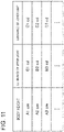
- the face image acquisition unit 304 refers to table information in which body heights and luminances of the two light sources are defined in advance.
- the face image acquisition unit 304 controls the upper light 404 and the lower light 405 such that the necessary luminances can be obtained from the table information.
- Fig. 11 is a diagram illustrating an example of table information in which body heights and luminances of the two light sources are defined.
- the face image acquisition unit 304 acquires the luminance of the upper light 404 and the luminance of the lower light 405 based on the body height of the user.
- the face image acquisition unit 304 controls a current flowing through the upper light 404 and a current flowing through the lower light 405 such that the upper light 404 and the lower light 405 emit light with their respective luminances acquired.
- the face image acquisition unit 304 may use table information in which these relationships are defined in advance or may use a function (a function that outputs current values when receiving luminances).
- the face image acquisition unit 304 acquires the body height of the user in accordance with any method.
- a plurality of sensors for example, infrared distance sensors
- the plurality of sensors are disposed vertically at predetermined intervals.
- the face image acquisition unit 304 monitors the output of each of the plurality of sensors and measures the body height of the user from the difference in the output value of each sensor (the output of each voltage value if infrared distance sensors are used). That is, if the body height of the user is low, fewer sensors react to the user. If the body height of the user is high, more sensors react to the user.
- the face image acquisition unit 304 determines the body height of the user based on the outputs of the sensors that change depending on the body height of the user. That is, the face image acquisition unit 304 determines the body height of the user based on the locations of the sensors that react to the body height of the user.
- the face image acquisition unit 304 may determine the body height of the user by capturing an image of the user and analyzing the obtained image.
- the luminance of the upper light 404 and the luminance of the lower light 405 are set to initial values (default values).
- the gate apparatus 10 may control the luminance of the upper light 404 and the luminance of the lower light 405 based on the face detection by image processing or the output values of sensors.
- the passport possession determination unit 305 is means for determining whether the user possesses a correct passport.
- the passport possession determination unit 305 acquires MRZ information written in a Machine Readable Zone in a passport by controlling the scanner 402.
- the passport possession determination unit 305 reads out information stored in an IC chip by using the acquired MRZ information.
- the passport possession determination unit 305 decrypts information read out from an IC chip by using MRZ information acquired by the scanner 402 and acquires a face image stored in the IC chip.
- the passport possession determination unit 305 calculates the similarity between two sets of feature values (feature vectors). For this similarity, the chi-squared distance, the Euclidean distance, or the like may be used. A longer distance represents a lower similarity, and a shorter distance represents a higher similarity.
- the left-behind baggage alert unit 307 is means for giving, if there is an object in the baggage placement area 430, an alert about the left-behind baggage. More specifically, if the left-behind baggage alert unit 307 determines that the user has forgotten to take his or her baggage away from the baggage placement area 430, the left-behind baggage alert unit 307 outputs an alert about the left-behind baggage. The left-behind baggage alert unit 307 checks the baggage detection flag, upon completion of the emigration and immigration examination by the corresponding gate apparatus 10.
- the gate control unit 308 closes the gate 408 after the user who is allowed to pass through the gate 408 (the user who has passed the emigration and immigration examination) passes through the gate 408.
- the storage unit 309 is means for storing information necessary for the operation of the gate apparatus 10.
- Fig. 13 is a sequence diagram illustrating an example of an operation of the emigration and immigration examination system according to the first example embodiment.
- Fig. 13 is a sequence diagram illustrating an example of a system operation performed on the departure date of a user. The following example assumes that the user has previously registered his or her "gate user information (fingerprint image)" in the server apparatus 20 before the operation in Fig. 13 .
- the user who has performed the pre-registration for use of the system moves to a gate apparatus 10 and stands in front of the gate apparatus 10.
- the gate apparatus 10 acquires a fingerprint image of the user (step S01).
- the gate apparatus 10 If the baggage detection flag is set to "1" (Yes in step S07), the gate apparatus 10 outputs an alert about the left-behind baggage (step S08).
- the gate apparatus 10 can obtain a face image suitable for face matching. That is, by optimally controlling the luminances of the different lights, the gate apparatus 10 can obtain a high quality image (a face image), regardless of the body height of the user. More specifically, the gate apparatus 10 changes the luminance of the light emitted from the upper light 404 and the luminance of the light emitted from the lower light 405 such that the user is illuminated with uniform illuminance. As a result, for example, the brightness of the light emitted to the face or the like does not vary depending on the location, and biological information suitable for authentication is acquired.
- the gate apparatus 10 when the gate apparatus 10 acquires biological information about a face image, the gate apparatus 10 controls the luminance of the upper light 404 and the luminance of the lower light 405.
- this control on the two light sources is also applicable to when an iris image is acquired for authentication or when a fingerprint image is acquired for authentication. That is, when an iris image or a fingerprint image is acquired, the two light sources may be controlled such that an eye area or a finger is illuminated with light with uniform luminance.
- bio information may be alternatively stored in the server apparatus 20.
- face images, voiceprint information, iris information, or the like or feature values thereof may be stored as biological information.
- biological information other than a face image can be acquired from a passport
- the biological information other than a face image may be used to determine whether the examination target user possesses a correct passport.
- any one of the upper light 404 and the lower light 405 may be formed by a plurality of light sources.
- the face image acquisition unit 304 may change the luminance of the upper light 404 or the lower light 405. That is, by performing digital control on the plurality of light sources, the gate apparatus 10 may control the luminance of the light emitted to the face of the user.
- a middle light may also be attached to the gate apparatus 10 in addition to the above two light sources. That is, a middle light may be installed between the upper light 404 and the lower light 405, and the luminance of the middle light may be controlled.
- the face image acquisition unit 304 may control the luminances of the three light sources based on the body height of the user. That is, the gate apparatus 10 controls the luminances of the plurality of light sources such that the user is illuminated with light with uniform illuminance.
- the above luminances may be controlled based on other information.
- the luminances of the light sources may be controlled based on the length of the user's hair and whether the user is wearing glasses.
- the luminances of the light sources may be controlled by comprehensively taking a plurality of elements (the body height and the presence or absence of glasses) into account.
- the luminances of the lights emitted from the two light sources may be different between a tall user with glasses and a short user with glasses. Whether the user is wearing glasses can be determined by performing image processing using a template or by using a learning model obtained by machine learning.
- the gate apparatus 10 may analyze a captured face image and control the luminances of the two light sources based on the analysis result of the face image. For example, the gate apparatus 10 (the face image acquisition unit 304) divides a face image into a plurality of areas and calculates an average brightness value of pixels constituting each of the plurality of small areas. The gate apparatus 10 may control the two light sources such that the calculated average value indicates a predetermined value or more and the variation in brightness among the small areas (for example, the variance value or standard deviation) becomes smaller than a threshold. That is, the gate apparatus 10 may feed the analysis result of the captured face image back to the control of the two light sources, to acquire a face image having uniform brightness.
- the gate apparatus 10 may feed the analysis result of the captured face image back to the control of the two light sources, to acquire a face image having uniform brightness.
- the gate apparatus 10 may determine the content of the alert about left-behind baggage by using information obtained from the passport.
- the left-behind baggage alert unit 307 may change the content of the message or the display method based on information obtained from an MRZ or an IC chip in the passport.
- the left-behind baggage alert unit 307 may generate an alert message by using the name of the user. For example, if the name of the user is "Taro", the left-behind baggage alert unit 307 may output an alert message "Mr. Taro, please take your baggage with you".
- the left-behind baggage alert unit 307 may use a parametric speaker or the like having a strong directivity. By using a parametric speaker or the like, the left-behind baggage alert unit 307 can reliably send an alert message to the user.
- each of the example embodiments may be used individually or a plurality of example embodiments may be used in combination.
- part of a configuration according to one example embodiment may be replaced by a configuration according to another example embodiment.
- a configuration according to one example embodiment may be added to a configuration according to another example embodiment.
- addition, deletion, or replacement is possible between part of a configuration according to one example embodiment and another configuration.
- the present invention is suitably applicable, for example, to emigration and immigration examination systems at airports.
- the gate apparatus according to supplementary note 1 or 2, wherein the first light is installed in the ceiling portion to emit light to the user from above the user.
- the gate apparatus according to supplementary note 4, further including a second light installed to emit light to the user from below the user.
- the gate apparatus according to supplementary note 5, wherein the second light is installed to emit light in a direction of the main body, and further including a second reflective plate that reflects the light emitted from the second light.
- the gate apparatus according to any one of supplementary notes 1 to 6, further including:
- the gate apparatus according to any one of supplementary notes 1 to 7, wherein the main body faces the ceiling portion, the main body and the ceiling portion being connected to each other by the supporting portion, and the main body, the supporting portion, and the ceiling portion are formed in a shape of mirror symmetry of letter C.
- the gate apparatus according to any one of supplementary notes 1 to 8, further including a light control unit that controls luminance of at least the first light.
Applications Claiming Priority (1)
| Application Number | Priority Date | Filing Date | Title |
|---|---|---|---|
| PCT/JP2020/006212 WO2021166064A1 (ja) | 2020-02-18 | 2020-02-18 | ゲート装置 |
Publications (2)
| Publication Number | Publication Date |
|---|---|
| EP4108859A1 true EP4108859A1 (de) | 2022-12-28 |
| EP4108859A4 EP4108859A4 (de) | 2023-04-12 |
Family
ID=77390602
Family Applications (1)
| Application Number | Title | Priority Date | Filing Date |
|---|---|---|---|
| EP20920152.4A Pending EP4108859A4 (de) | 2020-02-18 | 2020-02-18 | Torvorrichtung |
Country Status (4)
| Country | Link |
|---|---|
| US (3) | US11947244B2 (de) |
| EP (1) | EP4108859A4 (de) |
| JP (1) | JP7276591B2 (de) |
| WO (1) | WO2021166064A1 (de) |
Families Citing this family (1)
| Publication number | Priority date | Publication date | Assignee | Title |
|---|---|---|---|---|
| WO2023053268A1 (ja) * | 2021-09-29 | 2023-04-06 | 日本電気株式会社 | システム、認証端末、認証端末の制御方法及び記憶媒体 |
Family Cites Families (13)
| Publication number | Priority date | Publication date | Assignee | Title |
|---|---|---|---|---|
| US20050068420A1 (en) * | 2003-09-30 | 2005-03-31 | Duggan Charles F. | All in one capture station for creating identification documents |
| JP4318565B2 (ja) * | 2004-02-25 | 2009-08-26 | 株式会社メイクソフトウェア | 写真自動販売機、写真自動販売機の制御方法、および写真自動販売機の制御プログラム |
| US20110167727A1 (en) * | 2008-02-22 | 2011-07-14 | Glory Ltd. | Gate apparatus |
| JP2009211556A (ja) * | 2008-03-05 | 2009-09-17 | Fujitsu Ltd | 生体認証装置 |
| ES2822293T3 (es) * | 2009-01-07 | 2021-04-30 | Magnetic Autocontrol Gmbh | Dispositivo para el control del paso de personas |
| US8674805B2 (en) * | 2009-07-02 | 2014-03-18 | Mountain Pass Systems, Llc | Access control system and method using radio-frequency identification and imaging |
| EP3118810A4 (de) * | 2014-03-14 | 2017-11-08 | Kabushiki Kaisha Toshiba | Informationsverarbeitungsverfahren und informationsverarbeitungssystem |
| EP3138082A1 (de) * | 2014-04-30 | 2017-03-08 | Cubic Corporation | Adaptive gate-fahrsteigbodenanzeige |
| JP2017027492A (ja) * | 2015-07-27 | 2017-02-02 | パナソニックIpマネジメント株式会社 | 顔照合装置およびこれを備えた顔照合システムならびに顔照合方法 |
| CN108701225B (zh) | 2016-02-26 | 2023-04-04 | 日本电气株式会社 | 面部辨识系统、面部辨识方法和存储介质 |
| EP3522118A4 (de) * | 2016-09-30 | 2019-10-09 | Panasonic Intellectual Property Management Co., Ltd. | Gate-vorrichtung |
| JP6993124B2 (ja) * | 2016-12-28 | 2022-01-13 | グローリー株式会社 | 顔照合装置及び顔照合方法 |
| JP7220373B2 (ja) * | 2018-06-28 | 2023-02-10 | パナソニックIpマネジメント株式会社 | ゲート装置及びシステム |
-
2020
- 2020-02-18 US US17/796,985 patent/US11947244B2/en active Active
- 2020-02-18 EP EP20920152.4A patent/EP4108859A4/de active Pending
- 2020-02-18 WO PCT/JP2020/006212 patent/WO2021166064A1/ja unknown
- 2020-02-18 JP JP2022501433A patent/JP7276591B2/ja active Active
-
2023
- 2023-10-24 US US18/383,138 patent/US20240053657A1/en active Pending
- 2023-10-25 US US18/383,504 patent/US20240053658A1/en active Pending
Also Published As
| Publication number | Publication date |
|---|---|
| JPWO2021166064A1 (de) | 2021-08-26 |
| US20240053657A1 (en) | 2024-02-15 |
| US20240053658A1 (en) | 2024-02-15 |
| US20230053965A1 (en) | 2023-02-23 |
| WO2021166064A1 (ja) | 2021-08-26 |
| EP4108859A4 (de) | 2023-04-12 |
| JP7276591B2 (ja) | 2023-05-18 |
| US11947244B2 (en) | 2024-04-02 |
Similar Documents
| Publication | Publication Date | Title |
|---|---|---|
| US20130088685A1 (en) | Iris Cameras | |
| US20240053658A1 (en) | Gate apparatus | |
| CN102523381A (zh) | 对无线设备的功能的受控访问 | |
| JP2000259814A (ja) | 画像処理装置及びその方法 | |
| US11756338B2 (en) | Authentication device, authentication method, and recording medium | |
| KR101724971B1 (ko) | 광각 카메라를 이용한 얼굴 인식 시스템 및 그를 이용한 얼굴 인식 방법 | |
| US9946929B2 (en) | Method of detecting boundaries of the human eye | |
| KR20150069799A (ko) | 얼굴 인증 방법 및 그 장치 | |
| EP4108860A1 (de) | Gate-vorrichtung, verfahren zur steuerung einer gate-vorrichtung und speichermedium | |
| EP4109873A1 (de) | Gate-vorrichtung, steuerverfahren für gate-vorrichtung und aufzeichnungsmedium | |
| JP2023126272A (ja) | 処理装置、処理装置の制御方法及びプログラム | |
| EP4089254A1 (de) | Gatevorrichtung, servervorrichtung, immobilisierungsinspektionssystem, verfahren zum steuern einer gatevorrichtung und verfahren zum steuern der servervorrichtung | |
| EP4123567A1 (de) | Gate-vorrichtung, authentifizierungssystem, gattersteuerungsverfahren und speichermedium | |
| US20230065328A1 (en) | Gate apparatus, control method of gate apparatus, and storage medium | |
| KR102439216B1 (ko) | 인공지능 딥러닝 모델을 이용한 마스크 착용 얼굴 인식 방법 및 서버 | |
| US20230056195A1 (en) | Gate apparatus, management server, emigration and immigration examination system,and emigration and immigration examination method | |
| KR102583982B1 (ko) | 비대면 출입 통제 방법 및 이를 수행하는 출입 통제 시스템 | |
| US11256939B2 (en) | Methods, systems and computer program products for eye based spoof detection | |
| JP7424469B2 (ja) | ゲートシステム、ゲート装置、その画像処理方法、およびプログラム、ならびに、ゲート装置の配置方法 | |
| KR20220105738A (ko) | 얼굴 인식 기반의 검역 시스템 | |
| JP2023079045A (ja) | 画像処理装置、画像処理方法、およびプログラム |
Legal Events
| Date | Code | Title | Description |
|---|---|---|---|
| STAA | Information on the status of an ep patent application or granted ep patent |
Free format text: STATUS: THE INTERNATIONAL PUBLICATION HAS BEEN MADE |
|
| PUAI | Public reference made under article 153(3) epc to a published international application that has entered the european phase |
Free format text: ORIGINAL CODE: 0009012 |
|
| STAA | Information on the status of an ep patent application or granted ep patent |
Free format text: STATUS: REQUEST FOR EXAMINATION WAS MADE |
|
| 17P | Request for examination filed |
Effective date: 20220909 |
|
| AK | Designated contracting states |
Kind code of ref document: A1 Designated state(s): AL AT BE BG CH CY CZ DE DK EE ES FI FR GB GR HR HU IE IS IT LI LT LU LV MC MK MT NL NO PL PT RO RS SE SI SK SM TR |
|
| REG | Reference to a national code |
Ref country code: DE Ref legal event code: R079 Free format text: PREVIOUS MAIN CLASS: E05B0049000000 Ipc: G03B0015070000 |
|
| A4 | Supplementary search report drawn up and despatched |
Effective date: 20230313 |
|
| RIC1 | Information provided on ipc code assigned before grant |
Ipc: G06F 21/32 20130101ALI20230306BHEP Ipc: G07C 9/00 20060101ALI20230306BHEP Ipc: E05B 49/00 20060101ALI20230306BHEP Ipc: G03B 15/07 20060101AFI20230306BHEP |
|
| DAV | Request for validation of the european patent (deleted) | ||
| DAX | Request for extension of the european patent (deleted) |