EP4108612A1 - Withdrawal system for withdrawing article from packaging box - Google Patents
Withdrawal system for withdrawing article from packaging box Download PDFInfo
- Publication number
- EP4108612A1 EP4108612A1 EP21757585.1A EP21757585A EP4108612A1 EP 4108612 A1 EP4108612 A1 EP 4108612A1 EP 21757585 A EP21757585 A EP 21757585A EP 4108612 A1 EP4108612 A1 EP 4108612A1
- Authority
- EP
- European Patent Office
- Prior art keywords
- packing box
- holding frame
- frame
- box
- article
- Prior art date
- Legal status (The legal status is an assumption and is not a legal conclusion. Google has not performed a legal analysis and makes no representation as to the accuracy of the status listed.)
- Pending
Links
- 238000004806 packaging method and process Methods 0.000 title 1
- 238000012856 packing Methods 0.000 claims abstract description 144
- 230000000295 complement effect Effects 0.000 claims description 3
- 206010016173 Fall Diseases 0.000 abstract 1
- 238000004519 manufacturing process Methods 0.000 description 6
- 239000003638 chemical reducing agent Substances 0.000 description 4
- 238000000034 method Methods 0.000 description 4
- 239000002390 adhesive tape Substances 0.000 description 3
- 230000008602 contraction Effects 0.000 description 2
- 230000035939 shock Effects 0.000 description 2
- 206010000372 Accident at work Diseases 0.000 description 1
- 238000007792 addition Methods 0.000 description 1
- 238000013459 approach Methods 0.000 description 1
- 230000008878 coupling Effects 0.000 description 1
- 238000010168 coupling process Methods 0.000 description 1
- 238000005859 coupling reaction Methods 0.000 description 1
- 230000000694 effects Effects 0.000 description 1
- 239000002245 particle Substances 0.000 description 1
- 230000003252 repetitive effect Effects 0.000 description 1
- 230000001360 synchronised effect Effects 0.000 description 1
- 229920003002 synthetic resin Polymers 0.000 description 1
- 239000000057 synthetic resin Substances 0.000 description 1
- 239000002699 waste material Substances 0.000 description 1
Images



Classifications
-
- B—PERFORMING OPERATIONS; TRANSPORTING
- B65—CONVEYING; PACKING; STORING; HANDLING THIN OR FILAMENTARY MATERIAL
- B65G—TRANSPORT OR STORAGE DEVICES, e.g. CONVEYORS FOR LOADING OR TIPPING, SHOP CONVEYOR SYSTEMS OR PNEUMATIC TUBE CONVEYORS
- B65G65/00—Loading or unloading
-
- B—PERFORMING OPERATIONS; TRANSPORTING
- B65—CONVEYING; PACKING; STORING; HANDLING THIN OR FILAMENTARY MATERIAL
- B65G—TRANSPORT OR STORAGE DEVICES, e.g. CONVEYORS FOR LOADING OR TIPPING, SHOP CONVEYOR SYSTEMS OR PNEUMATIC TUBE CONVEYORS
- B65G65/00—Loading or unloading
- B65G65/23—Devices for tilting and emptying of containers
-
- B—PERFORMING OPERATIONS; TRANSPORTING
- B65—CONVEYING; PACKING; STORING; HANDLING THIN OR FILAMENTARY MATERIAL
- B65B—MACHINES, APPARATUS OR DEVICES FOR, OR METHODS OF, PACKAGING ARTICLES OR MATERIALS; UNPACKING
- B65B69/00—Unpacking of articles or materials, not otherwise provided for
-
- B—PERFORMING OPERATIONS; TRANSPORTING
- B65—CONVEYING; PACKING; STORING; HANDLING THIN OR FILAMENTARY MATERIAL
- B65G—TRANSPORT OR STORAGE DEVICES, e.g. CONVEYORS FOR LOADING OR TIPPING, SHOP CONVEYOR SYSTEMS OR PNEUMATIC TUBE CONVEYORS
- B65G47/00—Article or material-handling devices associated with conveyors; Methods employing such devices
- B65G47/22—Devices influencing the relative position or the attitude of articles during transit by conveyors
- B65G47/24—Devices influencing the relative position or the attitude of articles during transit by conveyors orientating the articles
- B65G47/248—Devices influencing the relative position or the attitude of articles during transit by conveyors orientating the articles by turning over or inverting them
- B65G47/252—Devices influencing the relative position or the attitude of articles during transit by conveyors orientating the articles by turning over or inverting them about an axis substantially perpendicular to the conveying direction
-
- B—PERFORMING OPERATIONS; TRANSPORTING
- B65—CONVEYING; PACKING; STORING; HANDLING THIN OR FILAMENTARY MATERIAL
- B65G—TRANSPORT OR STORAGE DEVICES, e.g. CONVEYORS FOR LOADING OR TIPPING, SHOP CONVEYOR SYSTEMS OR PNEUMATIC TUBE CONVEYORS
- B65G47/00—Article or material-handling devices associated with conveyors; Methods employing such devices
- B65G47/74—Feeding, transfer, or discharging devices of particular kinds or types
- B65G47/90—Devices for picking-up and depositing articles or materials
- B65G47/901—Devices for picking-up and depositing articles or materials provided with drive systems with rectilinear movements only
-
- B—PERFORMING OPERATIONS; TRANSPORTING
- B65—CONVEYING; PACKING; STORING; HANDLING THIN OR FILAMENTARY MATERIAL
- B65G—TRANSPORT OR STORAGE DEVICES, e.g. CONVEYORS FOR LOADING OR TIPPING, SHOP CONVEYOR SYSTEMS OR PNEUMATIC TUBE CONVEYORS
- B65G47/00—Article or material-handling devices associated with conveyors; Methods employing such devices
- B65G47/74—Feeding, transfer, or discharging devices of particular kinds or types
- B65G47/90—Devices for picking-up and depositing articles or materials
- B65G47/902—Devices for picking-up and depositing articles or materials provided with drive systems incorporating rotary and rectilinear movements
-
- B—PERFORMING OPERATIONS; TRANSPORTING
- B65—CONVEYING; PACKING; STORING; HANDLING THIN OR FILAMENTARY MATERIAL
- B65G—TRANSPORT OR STORAGE DEVICES, e.g. CONVEYORS FOR LOADING OR TIPPING, SHOP CONVEYOR SYSTEMS OR PNEUMATIC TUBE CONVEYORS
- B65G2201/00—Indexing codes relating to handling devices, e.g. conveyors, characterised by the type of product or load being conveyed or handled
- B65G2201/02—Articles
- B65G2201/0235—Containers
- B65G2201/025—Boxes
-
- B—PERFORMING OPERATIONS; TRANSPORTING
- B65—CONVEYING; PACKING; STORING; HANDLING THIN OR FILAMENTARY MATERIAL
- B65G—TRANSPORT OR STORAGE DEVICES, e.g. CONVEYORS FOR LOADING OR TIPPING, SHOP CONVEYOR SYSTEMS OR PNEUMATIC TUBE CONVEYORS
- B65G2814/00—Indexing codes relating to loading or unloading articles or bulk materials
- B65G2814/03—Loading or unloading means
- B65G2814/0301—General arrangements
- B65G2814/0314—General arrangements for moving bulk material downwards
- B65G2814/0316—General arrangements for moving bulk material downwards to a storage room
- B65G2814/0317—General arrangements for moving bulk material downwards to a storage room by tipping a container
-
- B—PERFORMING OPERATIONS; TRANSPORTING
- B65—CONVEYING; PACKING; STORING; HANDLING THIN OR FILAMENTARY MATERIAL
- B65G—TRANSPORT OR STORAGE DEVICES, e.g. CONVEYORS FOR LOADING OR TIPPING, SHOP CONVEYOR SYSTEMS OR PNEUMATIC TUBE CONVEYORS
- B65G47/00—Article or material-handling devices associated with conveyors; Methods employing such devices
- B65G47/74—Feeding, transfer, or discharging devices of particular kinds or types
- B65G47/90—Devices for picking-up and depositing articles or materials
- B65G47/91—Devices for picking-up and depositing articles or materials incorporating pneumatic, e.g. suction, grippers
- B65G47/914—Devices for picking-up and depositing articles or materials incorporating pneumatic, e.g. suction, grippers provided with drive systems incorporating rotary and rectilinear movements
Definitions
- the present disclosure relates to a system for withdrawing articles from a packing box, and more particularly, to a system for withdrawing articles from a packing box, by which heavy articles held in the packing box having the opened upper surface are withdrawn.
- a box having a cuboidal form is widely used as a packing container for carrying and storing articles.
- FIG. 1 illustrates a packing box of a widely used form.
- a packing box 1 is mainly made of a paper panel coated with a synthetic resin film, and is closed by four panels in which top and bottom surfaces of the packing box extend from side surfaces.
- the four panels 2 to 5 are made in two pairs, are folded from edges of the side surfaces to close the upper surface when ends of the four panels are abutted upon or adjacent to each other. A pair of panels 4 and 5 are folded in a faced state, and then the other pair of panels 2 and 3 are folded in a faced state, and are placed in an orientation perpendicular to the pair of panels 4 and 5 folded in advance.
- the upper surface of the packing box is closed, and the mutually abutting ends of the first pair of panels 2 and 3 folded and placed above are coupled to each other with an adhesive tape, and are closed to prevent the packing box 1 from being opened by an external force.
- the packing box 1 After the packing box 1 is first configured to close the bottom surface in the same mode as the upper surface, and then articles are put from the upper surface of the packing box 1 and are held in the inner portion of the packing box 1, the panels 2 to 5 forming the top surface are folded as described above, the ends of the pair of panels 2 and 3 are coupled by an adhesive tape, thereby closing the packing box 1.
- the closed packing box 1 is carried.
- the adhesive tape mutually coupling the panels 2 and 3 is cut, and then the panels 2 to 5 are all unfolded outward to open the upper surface. Then, the articles held in the inner portion of the packing box 1 are taken out.
- the packing box according to the invention of Document 1 merely discloses a configuration in which a consumer stores the articles in the packing box and makes it convenient to draw the articles one by one if necessary, but does not suggest a configuration suitable to draw the articles from the packing box required at a mass production manufacturing factory.
- the packing box of this Document 2 merely facilitates operations of opening the packing box and withdrawing of the articles, and does not suggest a configuration or a device for automating the withdrawing operation.
- the present disclosure is directed to provide a system for withdrawing articles from a packing box.
- the present disclosure is directed to provide a system for automatically withdrawing articles from a packing box, an upper surface of which is opened.
- the present disclosure is directed to provide a withdrawing system having a configuration where, when articles held in a packing box is heavy in weight and is easily damaged, the articles are allowed to be drawn without being damaged by a fall, a shock, etc. while not using a force of a person in a process of withdrawing the articles.
- an article withdrawing system configured to withdraw articles held in a packing box, the upper surface of which is opened.
- the article withdrawing system of the present disclosure includes:
- first stage configured to hold a packing box carried with an upper surface thereof opened and to reverse the packing box such that articles held in the packing box are allowed to fall down; and a second stage configured to support and hold the articles falling down from the first stage.
- the first stage may include a support unit configured to support and move the packing box upward and downward, a box holding frame on which the support unit is mounted, a linear motion frame to which the box holding frame is rotatably coupled, a main frame located and supported on the ground, with the linear motion frame being coupled to and supported on the main frame so to be linearly movable, and a first rotation drive means disposed on the linear motion frame and for rotatably driving the box holding frame.
- the second stage may include an article holding frame that has a holding surface having a shape complemented by a shape of the article so as to hold the article falling down from the first stage, a fixed frame located and supported on the ground, with the article holding frame being rotatably coupled to the fixing frame, and a second rotation drive means for rotating the article holding frame relative to the fixed frame.
- the article holding frame of the second stage may be rotated relative to the fixed frame such that the holding surface is faced downward.
- the packing box may be raised by the support unit such that the upper surface of the packing box comes close to or be in contact with the holding surface after the linear motion frame of the first stage is linearly moved such that the opened upper surface of the packing box faces the holding surface of the article holding frame.
- the box holding frame of the first stage and the article holding frame of the second stage may be respectively rotated relative to the linear motion frame and the main frame in a state where the upper surface of the packing box comes close to or is in contact with the holding surface, so that a position of the packing box is reversed and so that the articles held in the packing box fall to be held in the holding frame.
- the box holding frame of the first stage is separated from the article holding frame of the second stage. In this state, the articles are held in the box holding frame of the first stage, and the packing box having the opened upper surface is placed therein.
- the article holding frame of the second stage is rotated relative to the fixed frame such that the holding surface faces the bottom side, and the linear motion frame is linearly moved relative to the main frame on the first stage so that the box holding frame is placed below the article holding frame. Accordingly, the opened upper surface of the packing box is caused to face the holding surface of the article holding frame of the first stage.
- the packing box is raised by the support unit so that the opened top surface of the packing box approximates or abutted against the holding surface. Then, the box holding frame of the first stage and the article holding frame of the second stage are respectively rotated relative to the linear motion frame and the main frame, so that the position of the packing box is inversed, the articles held in the packing box fall to be held in the article holding frame.
- the articles deviate from the packing box, and are held on the holding surface of the article holding frame. Subsequently, the support unit is moved up or down with the packing box supported, moves back from the holding surface of the article holding frame, and returns to an initial state.
- the articles are withdrawn from the packing box, and each of the packing box and the article are carried to a place to be used or a waste place by separate carrying units.
- the support unit of the first stage may include: a first plate configured to support a bottom surface of the packing box; first actuators configured to actuate the first place to move up or down; two second plates configured to compress and support opposite sides of the packing box at opposite sides of a rotation axis of the box holding frame, respectively; second actuators configured to actuate the second plates so as to be approached to or separated from sides of the packing box, respectively; a fixed plate on which the second actuators is disposed; and first actuators configured to move the fixed plates upward or downward and fixed to the box holding frame.
- the packing box supposed to withdraw particles in the article withdrawing system of the present disclosure may be provided with an upper surface panel covering the upper surface.
- the upper surface panel may be opened prior to being introduced into the article withdrawing system of the present disclosure and then be folded from the upper surface, but may act as an obstacle factor against actuation of the article withdrawing system.
- the support unit may be provided with a vacuum suction unit configured to draw the upper surface panel under vacuum in a state where the upper surface panel closing the upper surface of the packing box is unfolded from the upper surface, and that maintains the unfolded state.
- the article withdrawing system of the present disclosure may be configured such that:
- the box holding frame and the article holding frame may face each other, and may be rotated and reversed about the same axis.
- the article withdrawing system of the present disclosure may be configured such that: up-down movement plates and fourth actuators configured to drive the up-down movement plates to move upward and downward are provided between the holding surfaces of the article holding frame, such that, when the articles fall down from the packing box supported in the box holding frame and are disposed by the article holding frame, the up-down movement plates in an elevated state support the articles and are moved downward.
- an operation of withdrawing the articles from the packing box is automatically conducted, and an operation based on a worker is not required.
- the worker is prevented from doing an unreasonable operation due to either a time delay resulting from the worker who withdraws the article that is heavy in weight or repetitive withdrawal of the heavy articles.
- the article is prevented from crashing against another object or falling to the ground to suffer damage.
- the upper surface panel folded from the packing box is allowed to maintain the unfolded state without being an obstacle against the
- the article may get an impact caused by a fall in the case where a gap is large between a position of the article at the packing box and a holding surface of an article holding frame.
- an impact caused by a fall does not occur while the article falls from the packing box to the holding surface frame of the article holding frame while the lift plate is contracted in a state in which the lift plate approaches and supports the articles.
- the withdrawing system is configured to withdraw articles from a packing box illustrated in FIG. 1 .
- Upper surface panels 3 and 4 covering an upper surface of the packing box 1 are all open and unfolded, and a film roll 9 rolled in a cylindrical shape is contained as an article to be withdrawn by the withdrawing system according to the present embodiment in a space of an inner portion of the packing box.
- the film roll 9 takes the form of a roll around which a film is wound, and has a weight of a high level.
- Some components of the withdrawing system according to the present embodiment are configured to be suitable to withdraw the film roll 9, but the article withdrawn through the withdrawing system according to the present embodiment is not limited to the film roll, and thus includes all articles which are held in the packing box 1 and may depart from the packing box 1 by reverse of the packing box 1.
- FIGS. 2 and 3 The withdrawing system according to the embodiment of the present disclosure is illustrated in FIGS. 2 and 3 .
- the configuration of the withdrawing system of the present disclosure will be described with reference to these figures.
- the withdrawing system of the present disclosure is made up of first stages 10 to 40 that reverse the packing box 1 so as to hold the packing box 1 carried in a state in which an upper surface of the packing box 1 is opened, and second stages 50 and 60 that support and hold the film roll 9 falling from the first stage 20.
- a main frame 10 that is placed and supported on the ground, and extends at a long length to be placed on and fixed to the ground, a linear movement frame 20 that is moved on the main frame 10 in a lengthwise direction C of the main frame 10, a box holding frame 30 that is rotatably coupled to the linear movement frame 20, and a support unit 40 that is installed on the box holding frame 30 and supports a bottom and sides of the packing box 1.
- a fixed frame 50 that is placed and supported on the ground, and an article holding frame 60 that is rotatably coupled to the fixed frame 50.
- the article holding frame 60 is provided with a pair of holding plates 61 that are placed apart from each other in a diameter direction of the film roll 9 with a concave curved surface as a holding surface that is complementary to a cylindrical shape of the film roll 9 so as to contain the film roll 9 falling from the packing box 1 supported on the support unit 40 among the first stages 10 to 40.
- the main frame 10 among the first stages 10 to 40 is configured in such a way that a plurality of props 11 placed on the ground is disposed vertically, and a box-shaped cross beam 12 extending to be long is integrally formed with the props 11, and is placed at upper ends of the props 11.
- a screw feed unit is embedded at each of upper surfaces of the props 11, and the linear movement frame 20 is meshed with a screw 13 of the screw feed unit so as to linearly move in the lengthwise direction of the main frame 10 according to rotation of the screw 13.
- the linear movement frame 20 is configured in the shape of a box, upper and rear surfaces of which are opened, and is placed apart from the upper surface of the main frame 10, and a first drive motor 21 as a rotation driving means for rotating the box holding frame 30 is fixedly coupled inside the linear movement frame 20.
- the first drive motor 21 is made up of a servo motor in which a rotational angle is controlled, and a reducer that reduces output of the servo motor, and a rotational shaft of the first drive motor 21 refers to an output shaft of the reducer.
- the box holding frame 30 is fixed to the rotational shaft of the first drive motor 21, and is rotated according to rotation of the first drive motor 21.
- FIG. 4 illustrates longitudinal cross-sectional views of the first stages 10 to 40.
- the box holding frame 30 is made up of a first portion 31 which holds the packing box 1, on which the support unit 40 is mounted, which extends along a rotation axis A of the box holding frame 30, and has the form of a box in which an upper surface and one side are opened, and a second portion 32 which vertically extends upward from the portion of the box form, and is coupled to the first drive motor 21.
- a first plate 41 in which the lower surface of the packing box 1 is placed, is disposed on the lower surface of a first portion 31 of the box holding frame 30, and two first actuators 42, which actuate the first plate 41 upward and downward, are fixed to a side of the first portion 31 of the box holding frame 30.
- Two second plates 43 which respectively pressurize the opposite sides of the packing box 1 at opposite sides of the rotation axis A of the box holding frame 30, are disposed on upper sides of sidewalls (32 in FIG. 4 ) of the box holding frame 30, respectively.
- second actuators 44 which are disposed on one of the second plates 43 in parallel by twos, and which actuate the second plates 43 so as to be approximate to and be separated from the sides of the packing box 1, and the second actuators 44 are fixed to fixed plates 45 that are disposed horizontally.
- Third actuators 46 that actuate the fixed plates 45 upward and downward in an up-down direction and are fixed to the box holding frame 30, and a pair of linear guides 47 that guide upward and downward actuations of the fixed plates 45 and are disposed in parallel with the third actuators 46 are fixed to the first portion 31 of the box holding frame 30.
- a support plate 49 which surrounds corners of the lower surface of the packing box 1 at four corners thereof, is disposed on the first plate 41.
- the first plate 41 is placed on the lower surface of the first portion 31 of the box holding frame 30, supports the lower surface of the packing box 1, is actuated upward and downward by the actuation of the first actuators 42, and moves the packing box 1 upward and downward.
- the pair of second plates 43 are respectively disposed to abut opposite sides 5 of the packing box 1, and are supported or separated by stretching and contracting of the second actuators 44.
- the fixed plates 45 at which the second plates 43 and the second actuators 44 are disposed, are moved upward and downward by the third actuators 46, but are synchronized with the upward and downward actuations of the first plate 41 to move the packing box 1 upward and downward.
- the first, second and third actuators 42, 44 and 46 are all configured of a pneumatic cylinder and conduct stretch and contraction.
- these actuators are not necessarily the pneumatic cylinders, and anything may be used if they are elements performing telescopic linear actuation.
- Vacuum suction units 48 are disposed upward at the fixed plates 45 and the first plate 41, respectively. Positions at which the vacuum suction units 48 are disposed are positions at which the upper surface panels 3 and 4 unfolded from the upper surface of the packing box 1 when the packing box 1 is placed are placed at the first portion 31 of the box holding frame 30.
- the vacuum suction units 48 draw (or attract) upper surface panels 3 and 4 of the packing box 1 respectively, and allow the upper surface panels 3 and 4 to maintain the unfolded state.
- FIGS. 2 and 3 are the longitudinal cross-section views of the second stages 50 and 60.
- props 52 that extend perpendicular to a bottom plate 51 placed on the ground, and a cross beam 53 that is placed at upper ends of the props are provided.
- a box-shaped motor fixed frame 54 is attached on the cross beam 53, and a second drive motor 55 acting as a rotation driving means is provided on an inner side of the motor fixed frame 54.
- the second drive motor 55 is also made up of a servo motor, the rotational angle of which is controlled, and a speed reducer, and a rotational shaft of the second drive motor 55 also refers to an output shaft of the speed reducer.
- the article holding frame 60 is configured in the form of a box in which an upper surface and one side are opened, and a side opposite to the opened one side is coupled to the rotational shaft of the second drive motor 55.
- the article holding frame 60 is provide with sidewalls 62 on the opposite sides of the rotation axis B in the diameter direction, and a pair of holding plates 61, which have a concave curved surface that is complementary to a cylindrical shape of the film roll 9, are provided from upper ends of the sidewalls 62 to the inner side of the article holding frame 60 in the diameter direction.
- a pair of up-down movement plates 63, fourth actuators 64 moving the respective up-down movement plates 63 upward and downward, and linear guides 65 guiding the up-down movements of the up-down movement plates 63 are provided between the holding plates 61 and on a lower surface of the article holding frame 60.
- the up-down movement plates 62 support the film roll 9, and move upward or downward to allow the film roll 9 to rest on the holding plates 61 of the article holding frame 60 without getting a shock while being moved downward when the film roll 9 is moved upward or downward by the fourth actuators 64 and falls from the box holding frame 30 among the first stages 10 to 40 to the article holding frame 60 among the second stages 50 and 60.
- the rotation axis A of the box holding frame 30 among the first stages 10 to 40 and the rotation axis B of the article holding frame 60 among the second stages 50 and 60 is parallel with each other, and the box holding frame 30 is linearly moved between a position on a plane by the linear movement of the linear movement frame 20 and a position separated from a position overlapped with the article holding frame.
- the box holding frame 30 is rotatable relative to the article holding frame 60 between a position located below and a position located above in the up-down direction.
- FIGS. 2 and 3 illustrate an initial state of the withdrawing system.
- the article holding frame 30 of the first stages is in a state in which a position thereof does not overlap with that of the article holding frame 60 of the second stages 50 and 60 on a plan, and the first portion 31 is disposed below with respect to the rotation axis A of the box holding frame 30 so as to allow the packing box to be disposed on the article holding frame 60.
- FIG. 6 illustrates a state in which the packing box is introduced into the withdrawing system according to the present embodiment.
- the packing box 1 is disposed and supported on the first plate 41 of the support unit 40 attached to the box holding frame 30 among the first stages 10 to 40 by a carrying robot or another carry unit.
- the support plate 49 which is installed to corners of the first plate 41, functions to support the packing box 1 such that the packing box 1 is not moved on the horizontal plane.
- the second plates 43 of the support unit 40 move toward the packing box 1 to abut and support the sides 5 of the packing box 1 due to stretching of the second actuators 44, and the vacuum suction units 48 disposed on the first plate 41 and the fixed plates 45 draw the respective upper surface panels 3 and 4 of the opened and unfolded packing box 1, and fix the upper surface panels 3 and 4 of the packing box 1 in place.
- FIG. 7 illustrates a preparing step of withdrawing the film roll from the packing box.
- the linear movement frame 20 is linearly moved along the main frame 10, and the box holding frame 30 is moved in the lengthwise direction of the main frame 10.
- the rotation axis A of the box holding frame 30 and the rotation axis B of the article holding frame 60 overlap with each other, and both have a common rotation axis.
- the box holding frame 30 among the first stages 10 to 40 is disposed below the article holding frame 60 of the second stages 50 and 60, and the article holding frame 60 is rotated at 180 degrees and faces the packing box 1 disposed in the box holding frame 30 in which the holding plates 61 and up-down movement plate 62 are disposed below.
- FIG. 8 illustrates a step of supporting the packing box 1 between the box holding frame 30 and the article holding frame 60.
- the support unit 40 disposed in the article holding frame 30 is actuated.
- the first plate 41 supporting the lower surface of the packing box 1 and the fixed plates 45 to which the second plates 43 supporting the side of the packing box 1 are coupled are moved upward by the first actuators 42 and the third actuator 46, respectively. Thereby, the packing box 1 is moved toward the article holding frame 60.
- the up-down movement plate 62 disposed on the lower surface of the article holding frame 60 is moved downward by stretching operation of the fourth actuators 64.
- the packing box 1 is disposed between the box holding frame 30 and the article holding frame 60.
- FIG. 9 illustrates reversed states of the article holding frame 60 and the box holding frame 30.
- the box holding frame 30 and the article holding frame 60 are rotated together in one direction at an angle of 180 degrees with respect to the common rotation axes A and B, so that the article holding frame 60 is disposed below the box holding frame 30.
- the film roll 9 that has been held in the packing box 1 supported on the box holding frame 30 is supported on the holding plates 61 and the up-down movement plates 62 of the article holding frame 60 of the second stages 50 and 60
- the film roll 9 is supported by the up-down movement plate 62, and is supported and rested by the up-down movement plate 62 while the fourth actuators 64 are being contracted.
- the support unit 40 on the first stages conducts contraction actuation, and the packing box 1 is separated from the article holding frame 60 holding the film roll 9.
- the first plate 41 and the fixed plates 45 conduct backward movement operation, so that the packing box 1 comes into close contact with the first portion 31 of the box holding frame 30, and is separated from the article holding frame 60.
- the film roll 9 held in the packing box 1 is discharged from the packing box 1, and is held in the article holding frame 60.
- the linear movement frame 20 among the first stages 10 to 40 is linearly moved along the main frame 10, and the box holding frame 30 is separated from the article holding frame 60 of the second stages 50 and 60, is again rotated relative to the linear movement frame 20 at an angle of 180 degrees, and returns to the initial state.
- the packing box 1 and the film roll 9 are carried from the box holding frame 30 and the article holding frame 60 by a robot or another carrying unit, respectively.
Landscapes
- Engineering & Computer Science (AREA)
- Mechanical Engineering (AREA)
- Container Filling Or Packaging Operations (AREA)
- Control And Other Processes For Unpacking Of Materials (AREA)
- Auxiliary Devices For And Details Of Packaging Control (AREA)
- Warehouses Or Storage Devices (AREA)
Abstract
Description
- The present disclosure relates to a system for withdrawing articles from a packing box, and more particularly, to a system for withdrawing articles from a packing box, by which heavy articles held in the packing box having the opened upper surface are withdrawn.
- As a packing container for carrying and storing articles, a box having a cuboidal form is widely used.
-
FIG. 1 illustrates a packing box of a widely used form. - A
packing box 1 is mainly made of a paper panel coated with a synthetic resin film, and is closed by four panels in which top and bottom surfaces of the packing box extend from side surfaces. - Since the top and bottom surfaces of the packing box have the same structure, the upper surface will be described with reference to
FIG. 1 . The four panels 2 to 5 are made in two pairs, are folded from edges of the side surfaces to close the upper surface when ends of the four panels are abutted upon or adjacent to each other. A pair ofpanels panels 2 and 3 are folded in a faced state, and are placed in an orientation perpendicular to the pair ofpanels - In this manner, the upper surface of the packing box is closed, and the mutually abutting ends of the first pair of
panels 2 and 3 folded and placed above are coupled to each other with an adhesive tape, and are closed to prevent thepacking box 1 from being opened by an external force. - After the
packing box 1 is first configured to close the bottom surface in the same mode as the upper surface, and then articles are put from the upper surface of thepacking box 1 and are held in the inner portion of thepacking box 1, the panels 2 to 5 forming the top surface are folded as described above, the ends of the pair ofpanels 2 and 3 are coupled by an adhesive tape, thereby closing thepacking box 1. The closedpacking box 1 is carried. - Meanwhile, when an attempt is made to open the
packing box 1, which is configured in this manner and contains articles, and then to take out the articles, the adhesive tape mutually coupling thepanels 2 and 3 is cut, and then the panels 2 to 5 are all unfolded outward to open the upper surface. Then, the articles held in the inner portion of thepacking box 1 are taken out. - In a case where the articles held in the
packing box 1 are general consumer goods, there is no special problem. However, in a case of the articles used at a mass production manufacturing factory, an operation of aligning and carrying the articles in a given direction in order to take out the articles from thepacking box 1 and then put the articles into the manufacturing factory is a job requiring a lot of labor force in spite of a very simple operation, and becomes a cause of increasing manufacturing costs. - Especially, in a case where the articles held in the
packing box 1 are heavy in weight and are easily damaged, an immoderate force is applied to the body of a worker in a process in which the worker withdraws the articles, and thus the worker may lead to industrial accident. Particularly, there may occur a situation where the article falls to the ground and is broken because the worker does not cope with the weight of the article while withdrawing the article. - Meanwhile, an invention titled "Packing box having window structure for withdrawing stick cake goods" is disclosed in
Korean Patent Publication No. 10-1554009 Document 1 suggests a configuration that making it easier to draw the goods held in the packing box. - However, the packing box according to the invention of
Document 1 merely discloses a configuration in which a consumer stores the articles in the packing box and makes it convenient to draw the articles one by one if necessary, but does not suggest a configuration suitable to draw the articles from the packing box required at a mass production manufacturing factory. - Further, an invention titled "Packing box for easily withdrawing products" is disclosed in
Korean Patent Publication No. 10-1527654 - However, the packing box of this Document 2 merely facilitates operations of opening the packing box and withdrawing of the articles, and does not suggest a configuration or a device for automating the withdrawing operation.
- As described above, the prior arts suggest a technique of making it easy to draw the articles held in the packing box, and such packing box has a special form of making the withdrawing easy. However, in the prior arts, there is neither disclosure nor consideration for a system that makes it possible to automatically draw products, which are heavy in weight or are easily damaged, from a packing box having a general configuration.
- The present disclosure is directed to provide a system for withdrawing articles from a packing box.
- To be specific, the present disclosure is directed to provide a system for automatically withdrawing articles from a packing box, an upper surface of which is opened.
- Further, the present disclosure is directed to provide a withdrawing system having a configuration where, when articles held in a packing box is heavy in weight and is easily damaged, the articles are allowed to be drawn without being damaged by a fall, a shock, etc. while not using a force of a person in a process of withdrawing the articles.
- According to the present disclosure for realizing at least one of the aforementioned objects, provided is an article withdrawing system configured to withdraw articles held in a packing box, the upper surface of which is opened.
- The article withdrawing system of the present disclosure includes:
- a first stage configured to hold a packing box carried with an upper surface thereof opened and to reverse the packing box such that articles held in the packing box are allowed to fall down; and a second stage configured to support and hold the articles falling down from the first stage.
- The first stage may include a support unit configured to support and move the packing box upward and downward, a box holding frame on which the support unit is mounted, a linear motion frame to which the box holding frame is rotatably coupled, a main frame located and supported on the ground, with the linear motion frame being coupled to and supported on the main frame so to be linearly movable, and a first rotation drive means disposed on the linear motion frame and for rotatably driving the box holding frame.
- The second stage may include an article holding frame that has a holding surface having a shape complemented by a shape of the article so as to hold the article falling down from the first stage, a fixed frame located and supported on the ground, with the article holding frame being rotatably coupled to the fixing frame, and a second rotation drive means for rotating the article holding frame relative to the fixed frame.
- When the packing box in which the articles are contained is seated on the support unit of the first stage, the article holding frame of the second stage may be rotated relative to the fixed frame such that the holding surface is faced downward.
- The packing box may be raised by the support unit such that the upper surface of the packing box comes close to or be in contact with the holding surface after the linear motion frame of the first stage is linearly moved such that the opened upper surface of the packing box faces the holding surface of the article holding frame.
- The box holding frame of the first stage and the article holding frame of the second stage may be respectively rotated relative to the linear motion frame and the main frame in a state where the upper surface of the packing box comes close to or is in contact with the holding surface, so that a position of the packing box is reversed and so that the articles held in the packing box fall to be held in the holding frame.
- An operation of the article withdrawing system of the present disclosure according to this configuration will be described.
- The box holding frame of the first stage is separated from the article holding frame of the second stage. In this state, the articles are held in the box holding frame of the first stage, and the packing box having the opened upper surface is placed therein.
- Subsequently, the article holding frame of the second stage is rotated relative to the fixed frame such that the holding surface faces the bottom side, and the linear motion frame is linearly moved relative to the main frame on the first stage so that the box holding frame is placed below the article holding frame. Accordingly, the opened upper surface of the packing box is caused to face the holding surface of the article holding frame of the first stage.
- In this state, the packing box is raised by the support unit so that the opened top surface of the packing box approximates or abutted against the holding surface. Then, the box holding frame of the first stage and the article holding frame of the second stage are respectively rotated relative to the linear motion frame and the main frame, so that the position of the packing box is inversed, the articles held in the packing box fall to be held in the article holding frame.
- Accordingly, the articles deviate from the packing box, and are held on the holding surface of the article holding frame. Subsequently, the support unit is moved up or down with the packing box supported, moves back from the holding surface of the article holding frame, and returns to an initial state.
- As described above, the articles are withdrawn from the packing box, and each of the packing box and the article are carried to a place to be used or a waste place by separate carrying units.
- As a specific embodiment aspect of the article withdrawing system of the present disclosure, in the article withdrawing system of the present disclosure,
- The support unit of the first stage may include: a first plate configured to support a bottom surface of the packing box; first actuators configured to actuate the first place to move up or down; two second plates configured to compress and support opposite sides of the packing box at opposite sides of a rotation axis of the box holding frame, respectively; second actuators configured to actuate the second plates so as to be approached to or separated from sides of the packing box, respectively; a fixed plate on which the second actuators is disposed; and first actuators configured to move the fixed plates upward or downward and fixed to the box holding frame.
- Further, the packing box supposed to withdraw particles in the article withdrawing system of the present disclosure may be provided with an upper surface panel covering the upper surface.
- The upper surface panel may be opened prior to being introduced into the article withdrawing system of the present disclosure and then be folded from the upper surface, but may act as an obstacle factor against actuation of the article withdrawing system.
- The support unit may be provided with a vacuum suction unit configured to draw the upper surface panel under vacuum in a state where the upper surface panel closing the upper surface of the packing box is unfolded from the upper surface, and that maintains the unfolded state.
- As an additional feature of the present disclosure, the article withdrawing system of the present disclosure may be configured such that:
- the box holding frame and the article holding frame may be disposed in a position facing each other, and
- rotation axes of the box holding frame and the article holding frame may be parallel with each other, be disposed at the same height from the ground, and be perpendicular to the movement direction of the linear movement frame relative to the main frame. The rotation axis of the box holding frame and the rotation axis of the article holding frame may overlap each other due to linear movement of the linear movement frame relative to the main frame to form a common rotation axis.
- According to this configuration, only by the motion by which the box holding frame is linearly moved relative to the main frame and the motion by which the box holding frame and the article holding frame face each other, the box holding frame and the article holding frame may face each other, and may be rotated and reversed about the same axis.
- As an additional feature of the present disclosure, the article withdrawing system of the present disclosure may be configured such that:
up-down movement plates and fourth actuators configured to drive the up-down movement plates to move upward and downward are provided between the holding surfaces of the article holding frame, such that, when the articles fall down from the packing box supported in the box holding frame and are disposed by the article holding frame, the up-down movement plates in an elevated state support the articles and are moved downward. - When the article holding frame and the box holding frame are rotated and reversed together in a state in which the packing box is disposed between the frames while facing each other, the articles fall down from the pacing box supported on the box holding frame toward the holding surface of the article holding frame.
- According to the article withdrawing system, an operation of withdrawing the articles from the packing box is automatically conducted, and an operation based on a worker is not required. Thus, the worker is prevented from doing an unreasonable operation due to either a time delay resulting from the worker who withdraws the article that is heavy in weight or repetitive withdrawal of the heavy articles.
- Further, the article is prevented from crashing against another object or falling to the ground to suffer damage.
- According to the article withdrawing system of the present disclosure, the upper surface panel folded from the packing box is allowed to maintain the unfolded state without being an obstacle against the
- In a falling process of the article, the article may get an impact caused by a fall in the case where a gap is large between a position of the article at the packing box and a holding surface of an article holding frame. However, according to the article withdrawing system of the present disclosure, an impact caused by a fall does not occur while the article falls from the packing box to the holding surface frame of the article holding frame while the lift plate is contracted in a state in which the lift plate approaches and supports the articles.
-
-
FIG. 1 is a perspective view illustrating a state in which a packing box used in a withdrawing system according to an embodiment of the present disclosure is opened and a film roll is housed. -
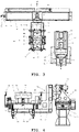
FIGS. 2 and3 are a perspective view and a top view illustrating an overall configuration of the withdrawing system according to an embodiment of the present disclosure. -
FIGS. 4 and5 are each longitudinal sectional views illustrating first and second stages that constitute the withdrawing system according to an embodiment of the present disclosure. -
FIGS. 6 to 9 are perspective views illustrating operations of the withdrawing system according to an embodiment of the present disclosure in order. - Hereinafter, as details for implementing the present disclosure, a configuration and an operation of a withdrawing system according to an embodiment of the present disclosure will be described with reference to the accompanying with drawings.
- The withdrawing system according to the present embodiment is configured to withdraw articles from a packing box illustrated in
FIG. 1 . -
Upper surface panels packing box 1 are all open and unfolded, and afilm roll 9 rolled in a cylindrical shape is contained as an article to be withdrawn by the withdrawing system according to the present embodiment in a space of an inner portion of the packing box. - The
film roll 9 takes the form of a roll around which a film is wound, and has a weight of a high level. Some components of the withdrawing system according to the present embodiment are configured to be suitable to withdraw thefilm roll 9, but the article withdrawn through the withdrawing system according to the present embodiment is not limited to the film roll, and thus includes all articles which are held in thepacking box 1 and may depart from thepacking box 1 by reverse of thepacking box 1. - The withdrawing system according to the embodiment of the present disclosure is illustrated in
FIGS. 2 and3 . The configuration of the withdrawing system of the present disclosure will be described with reference to these figures. - When roughly classified, the withdrawing system of the present disclosure is made up of
first stages 10 to 40 that reverse thepacking box 1 so as to hold thepacking box 1 carried in a state in which an upper surface of thepacking box 1 is opened, andsecond stages film roll 9 falling from thefirst stage 20. - As the
first stages 10 to 40, there are provided amain frame 10 that is placed and supported on the ground, and extends at a long length to be placed on and fixed to the ground, alinear movement frame 20 that is moved on themain frame 10 in a lengthwise direction C of themain frame 10, abox holding frame 30 that is rotatably coupled to thelinear movement frame 20, and asupport unit 40 that is installed on thebox holding frame 30 and supports a bottom and sides of thepacking box 1. - As the
second stages frame 50 that is placed and supported on the ground, and anarticle holding frame 60 that is rotatably coupled to the fixedframe 50. - The
article holding frame 60 is provided with a pair of holdingplates 61 that are placed apart from each other in a diameter direction of thefilm roll 9 with a concave curved surface as a holding surface that is complementary to a cylindrical shape of thefilm roll 9 so as to contain thefilm roll 9 falling from thepacking box 1 supported on thesupport unit 40 among thefirst stages 10 to 40. - First, configurations of the first stages will be specifically described.
- The
main frame 10 among thefirst stages 10 to 40 is configured in such a way that a plurality ofprops 11 placed on the ground is disposed vertically, and a box-shapedcross beam 12 extending to be long is integrally formed with theprops 11, and is placed at upper ends of theprops 11. - A screw feed unit is embedded at each of upper surfaces of the
props 11, and thelinear movement frame 20 is meshed with ascrew 13 of the screw feed unit so as to linearly move in the lengthwise direction of themain frame 10 according to rotation of thescrew 13. - The
linear movement frame 20 is configured in the shape of a box, upper and rear surfaces of which are opened, and is placed apart from the upper surface of themain frame 10, and afirst drive motor 21 as a rotation driving means for rotating thebox holding frame 30 is fixedly coupled inside thelinear movement frame 20. Thefirst drive motor 21 is made up of a servo motor in which a rotational angle is controlled, and a reducer that reduces output of the servo motor, and a rotational shaft of thefirst drive motor 21 refers to an output shaft of the reducer. - The
box holding frame 30 is fixed to the rotational shaft of thefirst drive motor 21, and is rotated according to rotation of thefirst drive motor 21. - The following description will be made along with
FIG. 4 that illustrates longitudinal cross-sectional views of thefirst stages 10 to 40. - The
box holding frame 30 is made up of afirst portion 31 which holds thepacking box 1, on which thesupport unit 40 is mounted, which extends along a rotation axis A of thebox holding frame 30, and has the form of a box in which an upper surface and one side are opened, and asecond portion 32 which vertically extends upward from the portion of the box form, and is coupled to thefirst drive motor 21. - In the
support unit 40 among thefirst stages 10 to 40, afirst plate 41, in which the lower surface of thepacking box 1 is placed, is disposed on the lower surface of afirst portion 31 of thebox holding frame 30, and twofirst actuators 42, which actuate thefirst plate 41 upward and downward, are fixed to a side of thefirst portion 31 of thebox holding frame 30. - Two
second plates 43, which respectively pressurize the opposite sides of thepacking box 1 at opposite sides of the rotation axis A of thebox holding frame 30, are disposed on upper sides of sidewalls (32 inFIG. 4 ) of thebox holding frame 30, respectively. Provided aresecond actuators 44 which are disposed on one of thesecond plates 43 in parallel by twos, and which actuate thesecond plates 43 so as to be approximate to and be separated from the sides of thepacking box 1, and thesecond actuators 44 are fixed to fixedplates 45 that are disposed horizontally. -
Third actuators 46 that actuate the fixedplates 45 upward and downward in an up-down direction and are fixed to thebox holding frame 30, and a pair oflinear guides 47 that guide upward and downward actuations of the fixedplates 45 and are disposed in parallel with thethird actuators 46 are fixed to thefirst portion 31 of thebox holding frame 30. - A
support plate 49, which surrounds corners of the lower surface of thepacking box 1 at four corners thereof, is disposed on thefirst plate 41. - According to this configuration, the
first plate 41 is placed on the lower surface of thefirst portion 31 of thebox holding frame 30, supports the lower surface of thepacking box 1, is actuated upward and downward by the actuation of thefirst actuators 42, and moves thepacking box 1 upward and downward. - The pair of
second plates 43 are respectively disposed to abutopposite sides 5 of thepacking box 1, and are supported or separated by stretching and contracting of thesecond actuators 44. - The fixed
plates 45, at which thesecond plates 43 and thesecond actuators 44 are disposed, are moved upward and downward by thethird actuators 46, but are synchronized with the upward and downward actuations of thefirst plate 41 to move thepacking box 1 upward and downward. - In the present embodiment, the first, second and
third actuators -
Vacuum suction units 48 are disposed upward at the fixedplates 45 and thefirst plate 41, respectively. Positions at which thevacuum suction units 48 are disposed are positions at which theupper surface panels packing box 1 when thepacking box 1 is placed are placed at thefirst portion 31 of thebox holding frame 30. - When the
box holding frame 30 among thefirst stages 10 to 40 and thearticle holding frame 60 of thesecond stages packing box 1, theupper surface panels packing box 1 are placed between thebox holding frame 30 and thearticle holding frame 60 so as not to become an obstacle against the actuation of the machine, thevacuum suction units 48 draw (or attract)upper surface panels packing box 1 respectively, and allow theupper surface panels - The configurations of the
second stages FIG. 5 together withFIGS. 2 and3 that are the longitudinal cross-section views of thesecond stages - As the fixed
frame 50 of thesecond stages props 52 that extend perpendicular to abottom plate 51 placed on the ground, and across beam 53 that is placed at upper ends of the props are provided. A box-shaped motor fixedframe 54 is attached on thecross beam 53, and asecond drive motor 55 acting as a rotation driving means is provided on an inner side of the motor fixedframe 54. - The
second drive motor 55 is also made up of a servo motor, the rotational angle of which is controlled, and a speed reducer, and a rotational shaft of thesecond drive motor 55 also refers to an output shaft of the speed reducer. - The
article holding frame 60 is configured in the form of a box in which an upper surface and one side are opened, and a side opposite to the opened one side is coupled to the rotational shaft of thesecond drive motor 55. - The
article holding frame 60 is provide withsidewalls 62 on the opposite sides of the rotation axis B in the diameter direction, and a pair of holdingplates 61, which have a concave curved surface that is complementary to a cylindrical shape of thefilm roll 9, are provided from upper ends of thesidewalls 62 to the inner side of thearticle holding frame 60 in the diameter direction. - A pair of up-down movement plates 63,
fourth actuators 64 moving the respective up-down movement plates 63 upward and downward, andlinear guides 65 guiding the up-down movements of the up-down movement plates 63 are provided between the holdingplates 61 and on a lower surface of thearticle holding frame 60. - The up-down
movement plates 62 support thefilm roll 9, and move upward or downward to allow thefilm roll 9 to rest on the holdingplates 61 of thearticle holding frame 60 without getting a shock while being moved downward when thefilm roll 9 is moved upward or downward by thefourth actuators 64 and falls from thebox holding frame 30 among thefirst stages 10 to 40 to thearticle holding frame 60 among thesecond stages - Meanwhile, the rotation axis A of the
box holding frame 30 among thefirst stages 10 to 40 and the rotation axis B of thearticle holding frame 60 among thesecond stages box holding frame 30 is linearly moved between a position on a plane by the linear movement of thelinear movement frame 20 and a position separated from a position overlapped with the article holding frame. - Due to the rotation caused by the
first drive motor 21, thebox holding frame 30 is rotatable relative to thearticle holding frame 60 between a position located below and a position located above in the up-down direction. - An operation of the withdrawing system according to the present embodiment having the aforementioned configuration will be described.
-
FIGS. 2 and3 illustrate an initial state of the withdrawing system. In this state, thearticle holding frame 30 of the first stages is in a state in which a position thereof does not overlap with that of thearticle holding frame 60 of thesecond stages first portion 31 is disposed below with respect to the rotation axis A of thebox holding frame 30 so as to allow the packing box to be disposed on thearticle holding frame 60. -
FIG. 6 illustrates a state in which the packing box is introduced into the withdrawing system according to the present embodiment. - In this state, the
packing box 1 is disposed and supported on thefirst plate 41 of thesupport unit 40 attached to thebox holding frame 30 among thefirst stages 10 to 40 by a carrying robot or another carry unit. Thesupport plate 49, which is installed to corners of thefirst plate 41, functions to support thepacking box 1 such that thepacking box 1 is not moved on the horizontal plane. - Further, the
second plates 43 of thesupport unit 40 move toward thepacking box 1 to abut and support thesides 5 of thepacking box 1 due to stretching of thesecond actuators 44, and thevacuum suction units 48 disposed on thefirst plate 41 and the fixedplates 45 draw the respectiveupper surface panels packing box 1, and fix theupper surface panels packing box 1 in place. -
FIG. 7 illustrates a preparing step of withdrawing the film roll from the packing box. - In a state in which the
packing box 1 is rested in thearticle holding frame 30, thelinear movement frame 20 is linearly moved along themain frame 10, and thebox holding frame 30 is moved in the lengthwise direction of themain frame 10. The rotation axis A of thebox holding frame 30 and the rotation axis B of thearticle holding frame 60 overlap with each other, and both have a common rotation axis. - Accordingly, in the state illustrated in
FIG. 7 , thebox holding frame 30 among thefirst stages 10 to 40 is disposed below thearticle holding frame 60 of thesecond stages article holding frame 60 is rotated at 180 degrees and faces thepacking box 1 disposed in thebox holding frame 30 in which the holdingplates 61 and up-downmovement plate 62 are disposed below. -
FIG. 8 illustrates a step of supporting thepacking box 1 between thebox holding frame 30 and thearticle holding frame 60. - In this step, the
support unit 40 disposed in thearticle holding frame 30 is actuated. - The
first plate 41 supporting the lower surface of thepacking box 1 and the fixedplates 45 to which thesecond plates 43 supporting the side of thepacking box 1 are coupled are moved upward by thefirst actuators 42 and thethird actuator 46, respectively. Thereby, thepacking box 1 is moved toward thearticle holding frame 60. The up-downmovement plate 62 disposed on the lower surface of thearticle holding frame 60 is moved downward by stretching operation of thefourth actuators 64. - Accordingly, the
packing box 1 is disposed between thebox holding frame 30 and thearticle holding frame 60. -
FIG. 9 illustrates reversed states of thearticle holding frame 60 and thebox holding frame 30. - The
box holding frame 30 and thearticle holding frame 60 are rotated together in one direction at an angle of 180 degrees with respect to the common rotation axes A and B, so that thearticle holding frame 60 is disposed below thebox holding frame 30. - Accordingly, the
film roll 9 that has been held in thepacking box 1 supported on thebox holding frame 30 is supported on the holdingplates 61 and the up-downmovement plates 62 of thearticle holding frame 60 of thesecond stages - In an early stage, the
film roll 9 is supported by the up-downmovement plate 62, and is supported and rested by the up-downmovement plate 62 while thefourth actuators 64 are being contracted. - Next, the
support unit 40 on the first stages conducts contraction actuation, and thepacking box 1 is separated from thearticle holding frame 60 holding thefilm roll 9. To be specific, thefirst plate 41 and the fixedplates 45 conduct backward movement operation, so that thepacking box 1 comes into close contact with thefirst portion 31 of thebox holding frame 30, and is separated from thearticle holding frame 60. - Consequently, the
film roll 9 held in thepacking box 1 is discharged from thepacking box 1, and is held in thearticle holding frame 60. - Subsequently, the
linear movement frame 20 among thefirst stages 10 to 40 is linearly moved along themain frame 10, and thebox holding frame 30 is separated from thearticle holding frame 60 of thesecond stages linear movement frame 20 at an angle of 180 degrees, and returns to the initial state. - Only the
empty packing box 1 is left on thebox holding frame 30 among thefirst stages 10 to 40, and thefilm roll 9 is left on thearticle holding frame 60 of thesecond stages - The
packing box 1 and thefilm roll 9 are carried from thebox holding frame 30 and thearticle holding frame 60 by a robot or another carrying unit, respectively. - This operation is repeated, and an operation of withdrawing the
film roll 9 from thepacking box 1 is continuously and automatically preformed. - Hereinabove, the configuration and the operation of the withdrawing system for withdrawing articles held in a packing box have been described, but the present disclosure is not limited to the foregoing embodiments, and various deformations and additions of elements are possible within a scope defined in the claims.
Claims (5)
- An article withdrawing system for withdrawing articles held in a packing box, an upper surface of which is opened, the article withdrawing system comprising:a first stage configured to reverse a packing box so as to hold the packing box carried with an upper surface opened and to enable the articles held in the packing box to fall down; anda second stage configured to support and hold the articles falling down from the first stage,wherein the first stage comprises a support unit configured to support the packing box and move the packing box upward or downward, a box holding frame on which the support unit is mounted, linear movement frames to which the box holding frame is rotatably coupled, a main frame located and supported on a ground, with the linear movement frames being coupled to and supported on the main frame so as to be linearly moved, and a first rotation driving means disposed in the linear movement frames and for rotatably driving the box holding frame,the second stage comprises an article holding frame having a holding surface of a shape complementary to a shape of the article so as to hold the articles falling down from the first stage, a fixed frame located and supported on the ground, with the article holding frame being rotatably coupled to the fixed frame, and a second rotation driving means for rotating the article holding frame relative to the fixed frame,when the packing box in which the articles are held is rested on the support unit of the first stage, the article holding frame of the second stage is rotated relative to the fixed frame such that the holding surface faces downward,after the linear movement frame of the first stage is linearly moved along the main frame such that the opened upper surface of the packing box faces the holding surface of the article holding frame of the second stage, the packing box is moved upward by the support unit such that the upper surface of the packing box approximates to or abuts the holding surface, andthe box holding frame of the first stage and the article holding frame of the second stage are respectively rotated relative to the linear movement frame and the main frame in the state in which the upper surface of the packing box approximates to or abuts the holding surface, so that the position of the packing box is reversed and the articles held in the packing box fall down and are held in the article holding frame.
- The article withdrawing system according to claim 1, wherein the support unit of the first stage comprises a first plate supporting the lower surface of the packing box, a first actuator configured to actuate the first plate in an upward or downward direction, a plurality of second plates abutting opposite sides of the packing box on the opposite sides of the rotation axis of the box holding frame, second actuators configured to actuate the second plate to approximate to or be separated relative to the sides of the packing box, fixed plates on which the second actuators are disposed, and third actuators fixed to the box holding frame and configured to actuate the fixed plates to move the fixed plates upward or downward in the vertical direction.
- The article withdrawing system of claim 2, wherein the support unit is provided with vacuum suction units configured to draw the upper surface panels under vacuum so as to allow the upper surface panels to be maintained in an unfolded state in a state in which the upper surface panels closing the upper surface of the packing box are unfolded from the upper surface.
- The article withdrawing system of claim 1, wherein the box holding frame and the article holding frame are disposed in a position facing each other, and
rotation axes of the box holding frame and the article holding frame are parallel with each other, are disposed at the same height from the ground, and are perpendicular to the movement direction of the linear movement frame relative to the main frame, and the rotation axis of the box holding frame and the rotation axis of the article holding frame overlap each other due to linear movement of the linear movement frame relative to the main frame to form a common rotation axis. - The article withdrawing system of claim 1, wherein up-down movement plates configured to move upward or downward and fourth actuators configured to drive the up-down movement plates to move upward or downward are provided between the holding surface of the article holding frame, such that, when the articles fall down from the packing box supported in the box holding frame and are disposed by the article holding frame, the up-down movement plates in an elevated state support the articles and are moved downward.
Applications Claiming Priority (2)
| Application Number | Priority Date | Filing Date | Title |
|---|---|---|---|
| KR1020200020684A KR102137935B1 (en) | 2020-02-19 | 2020-02-19 | System for Opening of Packaging Box |
| PCT/KR2021/002135 WO2021167406A1 (en) | 2020-02-19 | 2021-02-19 | Withdrawal system for withdrawing article from packaging box |
Publications (2)
| Publication Number | Publication Date |
|---|---|
| EP4108612A1 true EP4108612A1 (en) | 2022-12-28 |
| EP4108612A4 EP4108612A4 (en) | 2023-09-13 |
Family
ID=71894095
Family Applications (1)
| Application Number | Title | Priority Date | Filing Date |
|---|---|---|---|
| EP21757585.1A Pending EP4108612A4 (en) | 2020-02-19 | 2021-02-19 | Withdrawal system for withdrawing article from packaging box |
Country Status (6)
| Country | Link |
|---|---|
| US (1) | US12227376B2 (en) |
| EP (1) | EP4108612A4 (en) |
| KR (1) | KR102137935B1 (en) |
| CN (1) | CN115515871B (en) |
| AU (1) | AU2021222858B2 (en) |
| WO (1) | WO2021167406A1 (en) |
Families Citing this family (1)
| Publication number | Priority date | Publication date | Assignee | Title |
|---|---|---|---|---|
| KR102137935B1 (en) | 2020-02-19 | 2020-07-27 | 씨제이제일제당(주) | System for Opening of Packaging Box |
Family Cites Families (25)
| Publication number | Priority date | Publication date | Assignee | Title |
|---|---|---|---|---|
| US2865516A (en) * | 1953-11-10 | 1958-12-23 | Greenlee Bros & Co | Turnover apparatus |
| US3812982A (en) * | 1973-01-05 | 1974-05-28 | R Crandlemire | Case inverter |
| US4232782A (en) * | 1978-11-03 | 1980-11-11 | Shinko Kiko Co., Ltd. | Continuous conveyance system |
| JPS61140445A (en) | 1984-12-12 | 1986-06-27 | Daito Sangyo Kk | Automatic stack reversal mechanism |
| JP2529907B2 (en) * | 1991-08-30 | 1996-09-04 | ホシザキ電機株式会社 | Rack cup transfer method and apparatus |
| JP2551295B2 (en) * | 1992-03-06 | 1996-11-06 | 東洋製罐株式会社 | Automatic cardboard box opening, article removal, folding method and device |
| JP3477232B2 (en) * | 1993-11-30 | 2003-12-10 | 三菱重工業株式会社 | Waste paper transport box reversing machine |
| JPH07330160A (en) * | 1994-06-13 | 1995-12-19 | Nippon Alum Co Ltd | Device and method for discharging container |
| JPH0912133A (en) * | 1995-06-28 | 1997-01-14 | Japan Tobacco Inc | Box reversing device |
| US6139243A (en) * | 1997-07-09 | 2000-10-31 | Systemation Engineering | Method and system for flipping a tray of parts |
| WO1999020530A1 (en) * | 1997-10-22 | 1999-04-29 | Siemens Electrocom L.P. | Tray loader |
| US6481558B1 (en) * | 1998-12-18 | 2002-11-19 | Asyst Technologies, Inc. | Integrated load port-conveyor transfer system |
| JP3753917B2 (en) * | 2000-03-17 | 2006-03-08 | 茨木精機株式会社 | Method and apparatus for aligning and unpacking packages |
| FR2819481B1 (en) * | 2001-01-17 | 2003-09-05 | Cogema | DEVICE AND METHOD FOR TRANSFERRING OBJECTS BETWEEN TWO OPEN CONTAINERS |
| US6722841B2 (en) * | 2001-11-15 | 2004-04-20 | D B H Llc | Seed box inverter |
| JP2005082362A (en) * | 2003-09-10 | 2005-03-31 | Asahi Breweries Ltd | Box reversal method and device, and dust removal device using them |
| JP4634774B2 (en) * | 2004-10-22 | 2011-02-16 | アサヒビール株式会社 | Box reversal carry-out device |
| US7553119B2 (en) * | 2006-02-24 | 2009-06-30 | Northrop Grumman Systems Corporation | Mail tray unloader with shuttle transfer through system comprising tilting |
| JP5717007B2 (en) * | 2012-11-19 | 2015-05-13 | 株式会社安川電機 | Robot system, robot hand, robot |
| KR101527654B1 (en) | 2013-12-02 | 2015-06-17 | 유하정판 주식회사 | A packing box |
| KR101554009B1 (en) | 2014-02-17 | 2015-09-17 | 주식회사크라운제과 | Display and drawing slot structure of the packingbox for stick Cake goods |
| JP7060942B2 (en) * | 2016-11-01 | 2022-04-27 | トーヨーカネツ株式会社 | Automatic movement system |
| JP6867865B2 (en) * | 2017-05-02 | 2021-05-12 | 澁谷工業株式会社 | Container removal device |
| KR101902814B1 (en) * | 2018-05-29 | 2018-10-01 | 김경돈 | Automatic inspection of parts and exact loading device that can automatically detect the defective parts and transport them to the correct position |
| KR102137935B1 (en) * | 2020-02-19 | 2020-07-27 | 씨제이제일제당(주) | System for Opening of Packaging Box |
-
2020
- 2020-02-19 KR KR1020200020684A patent/KR102137935B1/en active Active
-
2021
- 2021-02-19 EP EP21757585.1A patent/EP4108612A4/en active Pending
- 2021-02-19 CN CN202180028856.8A patent/CN115515871B/en active Active
- 2021-02-19 AU AU2021222858A patent/AU2021222858B2/en active Active
- 2021-02-19 US US17/801,226 patent/US12227376B2/en active Active
- 2021-02-19 WO PCT/KR2021/002135 patent/WO2021167406A1/en not_active Ceased
Also Published As
| Publication number | Publication date |
|---|---|
| CN115515871A (en) | 2022-12-23 |
| AU2021222858A1 (en) | 2022-10-06 |
| US20220411205A1 (en) | 2022-12-29 |
| CN115515871B (en) | 2025-10-17 |
| KR102137935B1 (en) | 2020-07-27 |
| US12227376B2 (en) | 2025-02-18 |
| EP4108612A4 (en) | 2023-09-13 |
| AU2021222858B2 (en) | 2024-02-29 |
| WO2021167406A1 (en) | 2021-08-26 |
Similar Documents
| Publication | Publication Date | Title |
|---|---|---|
| AU2021222857B2 (en) | System for inverting packaging box | |
| CN108945614B (en) | Robot box opening equipment and box opening method | |
| CN109229568B (en) | Fully automatic opening and sealing machine | |
| JP6212265B2 (en) | Method and apparatus for reducing the height of a box having a square or rectangular cross section | |
| US7559884B2 (en) | Smart mandrel for container forming machines | |
| CN109229569B (en) | Fully automatic robot box unpacking machine | |
| CN109665313B (en) | Multi-station low-energy-consumption high-speed stacker crane for package finished product of bobbin | |
| US10850881B2 (en) | Method and apparatus for reconfiguring containers | |
| US12227376B2 (en) | Withdrawal system for withdrawing article from packaging box | |
| EP4108582A2 (en) | Opening system of packaging box | |
| US11273939B2 (en) | Case former with case-squaring assembly | |
| EP2737980A1 (en) | Robot disposed adjacent to a conveyance path and retractable in a parking position | |
| CN110255204B (en) | Unstacking, stacking and feeding system | |
| CN110937388B (en) | Commodity circulation is with dividing packet recovery processing device | |
| IT9012504A1 (en) | APPARATUS TO ROTATE A PANEL OR A PACK OF PANELS, TO DIFFERENTLY ORIENT THE PACKAGE ITSELF AGAINST THE CUTTING LINE OF A PANEL SAW | |
| CN214690468U (en) | Automatic gasket feeding equipment | |
| CN114715481A (en) | Cover clamping mechanism and packaging box finishing machine | |
| CN113148554A (en) | Intelligent logistics storage sorting management system | |
| CN223117969U (en) | Fixed limiting device for mechanical walking | |
| KR102611915B1 (en) | Box manufacturing apparatus and box manufacturing method | |
| KR102591188B1 (en) | Apparatus forming packing box and inserting unit product | |
| JP7844216B2 (en) | Automatic carton opening system | |
| CN114044333B (en) | Turnover device for telescopic film | |
| CN222061389U (en) | Material receiving device and packaging bag making equipment thereof | |
| KR102309518B1 (en) | Automatic mole change apparatus for gantry type former |
Legal Events
| Date | Code | Title | Description |
|---|---|---|---|
| STAA | Information on the status of an ep patent application or granted ep patent |
Free format text: STATUS: THE INTERNATIONAL PUBLICATION HAS BEEN MADE |
|
| PUAI | Public reference made under article 153(3) epc to a published international application that has entered the european phase |
Free format text: ORIGINAL CODE: 0009012 |
|
| STAA | Information on the status of an ep patent application or granted ep patent |
Free format text: STATUS: REQUEST FOR EXAMINATION WAS MADE |
|
| 17P | Request for examination filed |
Effective date: 20220909 |
|
| AK | Designated contracting states |
Kind code of ref document: A1 Designated state(s): AL AT BE BG CH CY CZ DE DK EE ES FI FR GB GR HR HU IE IS IT LI LT LU LV MC MK MT NL NO PL PT RO RS SE SI SK SM TR |
|
| DAV | Request for validation of the european patent (deleted) | ||
| DAX | Request for extension of the european patent (deleted) | ||
| P01 | Opt-out of the competence of the unified patent court (upc) registered |
Effective date: 20230606 |
|
| A4 | Supplementary search report drawn up and despatched |
Effective date: 20230810 |
|
| RIC1 | Information provided on ipc code assigned before grant |
Ipc: B65B 69/00 20060101ALI20230804BHEP Ipc: B65G 47/90 20060101ALI20230804BHEP Ipc: B65G 65/23 20060101AFI20230804BHEP |