EP4108606A1 - System for inverting packaging box - Google Patents
System for inverting packaging box Download PDFInfo
- Publication number
- EP4108606A1 EP4108606A1 EP21757023.3A EP21757023A EP4108606A1 EP 4108606 A1 EP4108606 A1 EP 4108606A1 EP 21757023 A EP21757023 A EP 21757023A EP 4108606 A1 EP4108606 A1 EP 4108606A1
- Authority
- EP
- European Patent Office
- Prior art keywords
- packing box
- panels
- conveyor
- disposed
- reversed
- Prior art date
- Legal status (The legal status is an assumption and is not a legal conclusion. Google has not performed a legal analysis and makes no representation as to the accuracy of the status listed.)
- Pending
Links
Images



Classifications
-
- B—PERFORMING OPERATIONS; TRANSPORTING
- B65—CONVEYING; PACKING; STORING; HANDLING THIN OR FILAMENTARY MATERIAL
- B65G—TRANSPORT OR STORAGE DEVICES, e.g. CONVEYORS FOR LOADING OR TIPPING, SHOP CONVEYOR SYSTEMS OR PNEUMATIC TUBE CONVEYORS
- B65G47/00—Article or material-handling devices associated with conveyors; Methods employing such devices
- B65G47/22—Devices influencing the relative position or the attitude of articles during transit by conveyors
- B65G47/24—Devices influencing the relative position or the attitude of articles during transit by conveyors orientating the articles
- B65G47/248—Devices influencing the relative position or the attitude of articles during transit by conveyors orientating the articles by turning over or inverting them
-
- B—PERFORMING OPERATIONS; TRANSPORTING
- B65—CONVEYING; PACKING; STORING; HANDLING THIN OR FILAMENTARY MATERIAL
- B65B—MACHINES, APPARATUS OR DEVICES FOR, OR METHODS OF, PACKAGING ARTICLES OR MATERIALS; UNPACKING
- B65B43/00—Forming, feeding, opening or setting-up containers or receptacles in association with packaging
- B65B43/38—Opening hinged lids
- B65B43/39—Opening-out closure flaps clear of bag, box, or carton mouth
-
- B—PERFORMING OPERATIONS; TRANSPORTING
- B65—CONVEYING; PACKING; STORING; HANDLING THIN OR FILAMENTARY MATERIAL
- B65B—MACHINES, APPARATUS OR DEVICES FOR, OR METHODS OF, PACKAGING ARTICLES OR MATERIALS; UNPACKING
- B65B69/00—Unpacking of articles or materials, not otherwise provided for
-
- B—PERFORMING OPERATIONS; TRANSPORTING
- B65—CONVEYING; PACKING; STORING; HANDLING THIN OR FILAMENTARY MATERIAL
- B65B—MACHINES, APPARATUS OR DEVICES FOR, OR METHODS OF, PACKAGING ARTICLES OR MATERIALS; UNPACKING
- B65B69/00—Unpacking of articles or materials, not otherwise provided for
- B65B69/0033—Unpacking of articles or materials, not otherwise provided for by cutting
-
- B—PERFORMING OPERATIONS; TRANSPORTING
- B65—CONVEYING; PACKING; STORING; HANDLING THIN OR FILAMENTARY MATERIAL
- B65G—TRANSPORT OR STORAGE DEVICES, e.g. CONVEYORS FOR LOADING OR TIPPING, SHOP CONVEYOR SYSTEMS OR PNEUMATIC TUBE CONVEYORS
- B65G15/00—Conveyors having endless load-conveying surfaces, i.e. belts and like continuous members, to which tractive effort is transmitted by means other than endless driving elements of similar configuration
- B65G15/10—Conveyors having endless load-conveying surfaces, i.e. belts and like continuous members, to which tractive effort is transmitted by means other than endless driving elements of similar configuration comprising two or more co-operating endless surfaces with parallel longitudinal axes, or a multiplicity of parallel elements, e.g. ropes defining an endless surface
- B65G15/12—Conveyors having endless load-conveying surfaces, i.e. belts and like continuous members, to which tractive effort is transmitted by means other than endless driving elements of similar configuration comprising two or more co-operating endless surfaces with parallel longitudinal axes, or a multiplicity of parallel elements, e.g. ropes defining an endless surface with two or more endless belts
-
- B—PERFORMING OPERATIONS; TRANSPORTING
- B65—CONVEYING; PACKING; STORING; HANDLING THIN OR FILAMENTARY MATERIAL
- B65G—TRANSPORT OR STORAGE DEVICES, e.g. CONVEYORS FOR LOADING OR TIPPING, SHOP CONVEYOR SYSTEMS OR PNEUMATIC TUBE CONVEYORS
- B65G37/00—Combinations of mechanical conveyors of the same kind, or of different kinds, of interest apart from their application in particular machines or use in particular manufacturing processes
-
- B—PERFORMING OPERATIONS; TRANSPORTING
- B65—CONVEYING; PACKING; STORING; HANDLING THIN OR FILAMENTARY MATERIAL
- B65G—TRANSPORT OR STORAGE DEVICES, e.g. CONVEYORS FOR LOADING OR TIPPING, SHOP CONVEYOR SYSTEMS OR PNEUMATIC TUBE CONVEYORS
- B65G47/00—Article or material-handling devices associated with conveyors; Methods employing such devices
- B65G47/74—Feeding, transfer, or discharging devices of particular kinds or types
- B65G47/90—Devices for picking-up and depositing articles or materials
- B65G47/91—Devices for picking-up and depositing articles or materials incorporating pneumatic, e.g. suction, grippers
- B65G47/914—Devices for picking-up and depositing articles or materials incorporating pneumatic, e.g. suction, grippers provided with drive systems incorporating rotary and rectilinear movements
-
- B—PERFORMING OPERATIONS; TRANSPORTING
- B65—CONVEYING; PACKING; STORING; HANDLING THIN OR FILAMENTARY MATERIAL
- B65G—TRANSPORT OR STORAGE DEVICES, e.g. CONVEYORS FOR LOADING OR TIPPING, SHOP CONVEYOR SYSTEMS OR PNEUMATIC TUBE CONVEYORS
- B65G47/00—Article or material-handling devices associated with conveyors; Methods employing such devices
- B65G47/74—Feeding, transfer, or discharging devices of particular kinds or types
- B65G47/90—Devices for picking-up and depositing articles or materials
- B65G47/91—Devices for picking-up and depositing articles or materials incorporating pneumatic, e.g. suction, grippers
- B65G47/918—Devices for picking-up and depositing articles or materials incorporating pneumatic, e.g. suction, grippers with at least two picking-up heads
-
- B—PERFORMING OPERATIONS; TRANSPORTING
- B65—CONVEYING; PACKING; STORING; HANDLING THIN OR FILAMENTARY MATERIAL
- B65B—MACHINES, APPARATUS OR DEVICES FOR, OR METHODS OF, PACKAGING ARTICLES OR MATERIALS; UNPACKING
- B65B51/00—Devices for, or methods of, sealing or securing package folds or closures; Devices for gathering or twisting wrappers, or necks of bags
- B65B51/02—Applying adhesives or sealing liquids
-
- B—PERFORMING OPERATIONS; TRANSPORTING
- B65—CONVEYING; PACKING; STORING; HANDLING THIN OR FILAMENTARY MATERIAL
- B65B—MACHINES, APPARATUS OR DEVICES FOR, OR METHODS OF, PACKAGING ARTICLES OR MATERIALS; UNPACKING
- B65B7/00—Closing containers or receptacles after filling
- B65B7/16—Closing semi-rigid or rigid containers or receptacles not deformed by, or not taking-up shape of, contents, e.g. boxes or cartons
- B65B7/20—Closing semi-rigid or rigid containers or receptacles not deformed by, or not taking-up shape of, contents, e.g. boxes or cartons by folding-down preformed flaps
-
- B—PERFORMING OPERATIONS; TRANSPORTING
- B65—CONVEYING; PACKING; STORING; HANDLING THIN OR FILAMENTARY MATERIAL
- B65G—TRANSPORT OR STORAGE DEVICES, e.g. CONVEYORS FOR LOADING OR TIPPING, SHOP CONVEYOR SYSTEMS OR PNEUMATIC TUBE CONVEYORS
- B65G2201/00—Indexing codes relating to handling devices, e.g. conveyors, characterised by the type of product or load being conveyed or handled
- B65G2201/02—Articles
- B65G2201/0235—Containers
- B65G2201/025—Boxes
-
- B—PERFORMING OPERATIONS; TRANSPORTING
- B65—CONVEYING; PACKING; STORING; HANDLING THIN OR FILAMENTARY MATERIAL
- B65G—TRANSPORT OR STORAGE DEVICES, e.g. CONVEYORS FOR LOADING OR TIPPING, SHOP CONVEYOR SYSTEMS OR PNEUMATIC TUBE CONVEYORS
- B65G2207/00—Indexing codes relating to constructional details, configuration and additional features of a handling device, e.g. Conveyors
- B65G2207/14—Combination of conveyors
-
- B—PERFORMING OPERATIONS; TRANSPORTING
- B65—CONVEYING; PACKING; STORING; HANDLING THIN OR FILAMENTARY MATERIAL
- B65G—TRANSPORT OR STORAGE DEVICES, e.g. CONVEYORS FOR LOADING OR TIPPING, SHOP CONVEYOR SYSTEMS OR PNEUMATIC TUBE CONVEYORS
- B65G2812/00—Indexing codes relating to the kind or type of conveyors
- B65G2812/01—Conveyors composed of several types of conveyors
- B65G2812/016—Conveyors composed of several types of conveyors for conveying material by co-operating units in tandem
- B65G2812/017—Conveyors composed of several types of conveyors for conveying material by co-operating units in tandem using tilted or side by side conveyor sections
Definitions
- the present disclosure relates to a reversing system for packing boxes, and more particularly, to a reversing system for packing boxes, one surface of each of which is opened, and from each of which products are withdrawn, wherein the reversing system reverses packing the empty packing box such that a surface of the packing box opposite to the one opened surface is opened.
- Boxes having a cuboidal shape are widely used as packing containers for transporting and storing products.
- FIG. 1 illustrates a packing box of a widely used shape.
- a packing box 1 is made up of a panel of a paper material that is mainly coated with a synthetic resin film, and upper and lower surfaces thereof are covered and closed by four upper and lower surface panels in which upper and lower surfaces extend from sides.
- FIG. 1 Since the upper and lower surfaces have the same structure, the upper surface will be mainly described with reference to FIG. 1 .
- Two of four upper surface panels 2 to 5 make a pair, and are folded from edges of the sides so that ends thereof come into contact with each other or become adjacent to each other, and thereby close the upper surface.
- a pair of second upper surface panels 4 and 5 are folded face to face, and then another pair of first upper surface panels 2 and 3 are folded face to face, and are disposed with an orientation perpendicular to the second upper surface panels 4 and 5 folded in advance.
- the packing box 1 is closed by first configuring the lower surface in the same manner as the upper surface, and disposing the products from the upper surface to contain it in an interior of the packing box 1. Then, as described above, the packing box 1 is closed by folding the upper surface panels 2 to 5 and by coupling ends of the first panels 2 and 3 using an adhesive tape, and the closed packing box 1 is transported.
- the packing box 1 which is configured in this manner and contains the products, is opened to be intended to withdraw the products, the adhesive tape coupling the first panels 2 and 3 with each other is cut, and all the second panels 2 and 5 are unfolded outwardly to open the upper surface, the products held in the inner portion of the packing box 1 are withdrawn.
- the lower surface of the empty packing box 1 is unfolded in the same manner as the upper surface of the empty packing box 1, the packing box 1 is folded and stacked, and is discharged as a recycling source.
- the work of opening the packing box 1, the work of drawing (or attracting) the products from the packing box 1, the work of aligning and carrying the withdrawn products, and the work of collecting the empty box from which the products are withdrawn for the purpose of recycling typically depends on manual labor of a worker.
- This manual labor delays a work time, requires a lot of expenditure, and is conducted by a person so that there may occurs a case in which a task is not properly conducted.
- the present disclosure discloses a configuration that is to intend to provide a reversing system that reverses a packing box so as to reverse an empty packing box, one surface of which is open and from which products are withdrawn, and to open a surface opposite to the one opened surface.
- the present disclosure is to intend to provide the reversing system in which work of reversing the empty packing box can be automatically carried out.
- the present disclosure is intended to provide the reversing system that reverses the empty packing box so as to enable an unopened opposite surface thereof to be opened without intervention of work of a person after the products are withdrawn from the packing box, one surface of which is opened.
- a reversing system for a packing box according to the present disclosure, wherein the reversing system reverses a box, an upper surface of which is opened, and from which products are withdrawn, so that a lower surface of the reversed empty box is disposed on an upper side thereof.
- the reversing system according to the present disclosure includes:
- a first conveyor configured to transfer an empty packing box, an upper surface of which is opened, from a withdrawn position at which products are withdrawn from a packing box to a reversed position at which a reversing operation is performed;
- a turning device configured to hold the packing box to be turned about a rotation axis horizontal to the ground, and to reverse the packing box;
- a second conveyor configured to carry the reversed packing box to a position in which a work of opening the bottom surface is conducted, wherein the turning device holds two sides, facing each other, among sides of the packing box, and to cause the packing pox to be turned and reversed using a portion between the holding locations of the two held sides, as a rotation axis.
- the turning device may hold two held sides, facing each other, among the sides of the packing box, and may turn and reverse the two held sides using a portion, which exists between the holding locations of the two held sides, as the rotation axis.
- the products may be withdrawn, and the empty packing box may be disposed at the reversed position by the first conveyor.
- the upper and lower surfaces of the disposed empty packing box may be inversed and carried to the position at which the lower surface is opened by the second conveyor.
- an upper surface panel covering an upper surface of a packing box may be provided on the upper surface, and an upper surface panel may be introduced into the reversing system when drawing (or attracting) products in an unfolded state, and
- the turning device may include: a movable frame that is actuated upwardly and downwardly in a reversed position, a pair of suction units that are respectively disposed at positions facing each other, is actuated to approximate to or be separated from each other, and is provided with suction members configured to draw the sides of the packing box at an approximated time; and bars actuated upwardly and downwardly by the movable frame and configured to cause the upper surface panel of opened and unfolded state to come into close contact with the sides.
- the empty packing box from which the products are withdrawn may be in a state in which the opened upper surface panel is unfolded. Accordingly, the upper surface panel may become a barrier factor in automatizing post-treatment of the empty packing box.
- the packing box prior to an operation of reversing the packing box, the packing box may be drawn after the side panels are brought in close contact with the sides of the packing box, and the turning operation may be conducted by raising the packing box from the conveyor.
- the upper surface panel unfolded by this operation does not become an obstacle to the upper surface panel of the packing box. Especially, without installing a separate unit for folding the upper surface panel of the packing box, an actuation of closely bringing the upper surface panel into close contact may be conducted together by the turning device.
- the upper surface panel may be comprised of a pair of first upper surface panels that are disposed vertically and face each other.
- the upper surface panels are configured as a pair, but a typical packing box has a pair of the upper surface panels.
- the bars may include a plurality of bars extending in parallel with the drawing direction of the suction members, wherein each of the bars comes into contact with each of the first upper surface panels when upward actuation of the movable frame, each of the suction units is provided with a mounting panel to which the suction member is attached, and each of the mounting panels may be configured to come into contact with each of the second upper surface panels at a time of downward actuation of the movable frame and to come into close contact with the sides of the packing box by the downward actuation.
- the movable frame is moved downwardly so that the packing box disposed on the first to second conveyors is held by the suction member, and is moved downwardly in order to turn the packing box after the movable frame is raised in a held state, and to turn the packing box to again put down the reversed packing box on the first to second conveyors.
- the movable frame In addition to the lifting motion for rotation of this packing box, when the packing box at which the reverse of any one of the packing boxes is completed and treated is withdrawn, the movable frame is raised to enter a waiting period. When the next packing box is introduced, the movable frame is moved downwardly to hold the packing box.
- an operation in which the upper surface panel of the packing box introduced by downward movement actuation in order to hold this newly introduced packing box comes into close contact with the sides of the packing box may be conducted. That is, the leading end of the mounting panel and bars bring the upper surface panel into contact with the sides of the packing box while the leading end of the mounting panel and the bars may be moved downwardly while butted with the first and second upper surface panels by the downward movement operation of the movable frame.
- a plurality of suction members are provided to each of the suction unit, the suction members disposed below the turning axis of the turning device are drawn by coming into contact with the sides of the packing box may be preferred to be drawn to the second upper surface panel of the packing box by coming into contact with the second upper surface panel of the packing box.
- the movable frame may be moved upwardly and downwardly, and may include a first frame extending to be parallel with a turning axis of the packing box, and a pair of second frames respectively disposed at opposite ends of the first frame and extending in a vertical direction, wherein the second frames are coupled to be move away from and approximate to the first frame in the turning axis of the packing box, and each of the suction units is provided with mounting panels to which the suction members are attached, and a rotation driving motor which is provided to each of the second frames, is rotatably driven using the rotation axis of the packing box that turns and drives the mounting panels as a rotation shaft is configured to rotate the mounting panels.
- the second conveyor may include a pair of conveyor belts extending from a reversed position to an opened position of a bottom surface of the packing box and parallel to each other
- the first conveyor may include a pair of conveyor belts disposed at the reversed position and extending between the conveyor belts of the second conveyor so as to be perpendicular to the second conveyor
- the reversing system may further include a third conveyor extending from an outer portion to a position adjacent to the second conveyor.
- the empty packing box from which products are withdrawn has upper and lower surfaces reversed automatically and can be treated for waste or recycle.
- the turning device conducts a close contact operation of the downward motion of a movable frame by the downward motion of the movable frame without being provided with a configuration for a separate motion.
- the close contact operation is conducted without conducting a separate motion for bringing the upper surface panels of the packing box in close contact, a process time is reduced. Further, since a separate actuation unit for the close contact operation is not required, the configuration of the reversing system can be simplified and produced cheaply.
- the suction members are disposed above and below a turning axis of the packing box, the reverse motion of the packing box is stably made, and the packing box is prevented from being separated during turning.
- the configuration of the reversing system is made compact by the disposition of the conveyors for carrying the packing box, and interference between various devices is removed.
- the reversing system of the present embodiment is configured to reverse an empty box after products are withdrawn from the packing box having the configuration illustrated in FIG. 1 .
- the packing box 1 is carried to the reversing system of the present embodiment by a conveyor belt or another carrying means
- the packing box 1 is discharged from the reversing system of the present embodiment, and then the adhesive tape is cut such that the panels covering the lower surface are opened are folded, the packing box 1 is stacked on another one, and is carried to another place for recycling.
- the reversing system of the present embodiment generally includes third conveyors 90 that convey the empty packing box 1 from the position at which the products are withdrawn to a position adjacent to a position at which the packing box 1 will be reversed, second conveyors 80 that are disposed perpendicular to the third conveyors 90 and convey the reversed packing box 1 to a position at which the panels of the lower surface are opened, first conveyors 70 that are disposed between the second conveyors 80 so as to be perpendicular to the second conveyors 80 and place the packing box 1 conveyed by the third conveyors 90 at a reversed position, a turning device 30 that holds, rotates, and reverses the packing box 1 that is disposed at the reversed position by the first conveyors 70, first and second stoppers 21 and 22 that allow the packing box 1 to be disposed at the reversed position, and a main frame 10 at which the turning device 30, the stoppers 21 and 22, and the first to third conveyors 70 to 90 are installed.
- the main frame 10 may be made up of several frames configured independently of one another. Either an opening system of the packing box 1 or a withdrawing system for withdrawing the products from the packing box 1may be disposed in this main frame 10 in addition to the reversing system of the present embodiment.
- main frame 10 is treated as a single element, and is disposed at positions different from each other.
- the frames belonging to the main frames 10 are referred to as the main frames, and are indicated by the same reference number.
- the turning device 30 holds and rotates the packing box 1 disposed at the reversed position by the first and third conveyors 70 and 90.
- Conveyor belts of the first to third conveyors 70 to 90 are disposed on the same plane that is approximately parallel to the ground, and the turning device 30 is installed at a portion extending upwardly from this plane at the main frame 10.
- the main frame 10 includes four vertical channels 11 extending vertically and a horizontal channel 12 extending horizontally between upper ends of the vertical channels 11. A space enclosed by the vertical channels 11 and the horizontal channel 12 form a reversing place in which the packing box 1 is reversed. Components of the turning device 30 are coupled to or suspended from the horizontal channel 12.
- the turning device 30 includes movable frames 31 and 32 suspending from the horizontal channel 12 and configured to be movable upwardly and downwardly.
- a vertically actuatable pneumatic cylinder 41 and four vertically extending linear guides 42 are coupled to the horizontal channels 12.
- a first frame 31 extending in parallel with a rotation axis (A of FIG. 7 ) serving as the rotation center of the packing box 1, and a pair of second frames 32 extending in a vertical direction, are provided on a leading end of the pneumatic cylinder 41 and leading ends of the linear guides 42.
- Linear actuators 43 including the pneumatic cylinder 41 and the linear guides 42 are provided at opposite ends of the first frame 31.
- the linear actuators 43 are driven in an extending direction of the first frame 31, i.e. in a direction of the rotation axis A, and upper ends of the second frames 32 are coupled to leading ends of the linear actuators 43.
- the second frames 32 are actuated in a direction as the same as or opposite to each other.
- Rotation driving motors 44 are coupled to lower ends of the respective second frames 32.
- Rotation shafts (not illustrated) of the rotation driving motors 44 are disposed on the rotation axis A, and are fixedly coupled to the second frames 32.
- Mounting panels 33 on which suction members 45 and 46 as suction units are disposed, are coupled to lower ends of the respective second frames 32.
- the mounting panels 33 are coupled to the rotation shafts of the rotation driving motors 44 so as to be rotatable.
- the two mounting panels 33 are disposed to face each other, and a total of five suction members 45 and 46 are coupled to opposite surfaces of the mounting panels 33.
- the three first suction members 45 are disposed in parallel at an upper side of the rotation axis A, and the two second suction members 46 are disposed at a lower side of the rotation axis A.
- the suction members 45 and 46 are connected to a vacuum source to draw an object under vacuum, and function to draw and fix the packing box 1 disposed between the mounting panels 33. This will be described below, the first suction members 45 draw (or attract) the upper surface panels 2 and 3 which are opened from the packing box 1, and second suction members 46 draw the sides of the packing box 1.
- the mounting bracket 35 extend from the mounting panels 33 at opposite sides of each of the mounting panels 33, and bars 36 are coupled to leading ends of each of the mounting brackets 35.
- the bars 36 extend from the leading ends of the mounting brackets 35 in a direction parallel with the rotation axis A.
- the two bars 36 coupled to one of the mounting panels 33 are separated in a width direction of the packing box 1.
- the third conveyors 90 include two conveyor belts extending in parallel with each other.
- the third conveyors 90 extend from a position, at which an empty packing box 1 is disposed after the products are withdrawn, to a position at which the second conveyors 80 are disposed.
- the second conveyors 80 also include two conveyor belts extending in parallel with each other, and extending from the reversed position to a position at which the bottom surface of the reversed packing box 1 is opened.
- the first conveyors 70 also include two conveyor belts extending in parallel with each other, the conveyor belts, and rollers (not illustrated) and motors (not illustrated) that turn and drive the conveyor belts constitute one assembly, and pneumatic cylinders and linear guides are provided as lifting devices (not illustrated) that vertically lift this assembly.
- the first conveyors 70 are disposed in a straight line with the third conveyors 90, with respect to each other, and a pair of conveyor belts constituting the first conveyors 70 are disposed between a pair of conveyor belts constituting the second conveyor belts80.
- the first conveyors 70 are raised to the upper sides of the second conveyors 80 by the lifting device (not illustrated), receive the packing box 1 introduced by the third conveyors 90, and cause the received packing box 1 to be disposed at the reversed position.
- the first conveyors 70 move down, and the packing box 1 is supported by the second conveyors 80, and the reverse actuation caused by the turning device 30 is carried out.
- the first conveyors 70 may be disposed at the same height as the second conveyors 80 so as to support the packing box 1 together with the second conveyors 80, and the first conveyors 70 may support the packing box 1 during the reverse actuation caused by the turning device 30.
- the packing box 1 is disposed at the reversed position by actuation control of the first to third conveyors 70 to 90, but during the reverse actuation, the movement of the packing box 1 is restricted to cause dislocation to be removed so that the suction members 45 and 46 and the bars 36 accurately hold the packing box 1 during the reverse actuation.
- the turning device 30 is disposed at the raised position illustrated in FIG. 2 .
- the pneumatic cylinder 41 is actuated in a contracted state, and raises the first and second frames 31 and 32 so that the suction members 45 and 46 and the bars 36 are disposed at the raised position.
- the second frames 32 are adapted in a state of being separated from each other by the contracted actuations of the linear actuators 43.
- the packing box 1 is introduced to the reversed position by the first and third conveyors 70 and 90.
- the pneumatic cylinder 41 is enlarged and actuated, so that the first and second frames 31 and 32 are moved down, and the mounting panels 33, the suction members 45 and 46, and the bars 36, which are attached to the frames, are also moved down.
- the mounting panels 33 and the bars 36 come into contact with the unfolded upper surface panels 2 and 6 by lowering actuation, respectively.
- the lower end faces of the mounting panels 33 are moved down while coming into contact with the two second upper surface panels 4 and 5, and bring the second upper surface panels 4 and 5 into close contact with the sides of the packing box 1.
- the respective bars 36 bring the first upper surface panels 2 and 3 into close contact with the sides of the packing box 1 while being in contact with the first upper surface panels 2 and 3.
- the rotation shafts of the rotation driving motors 44 are disposed at approximately geometric centers of the mutually facing sides of the packing box 1.
- the geometric centers of the sides of the packing box 1 are disposed on the rotation axis A.
- the linear actuators 43 are enlarged and actuated, so that the mounting panels 33 are moved in the directions approximating each other. Accordingly, the suction members 45 and 46 attached to the mounting panels 33 are brought in contact with the packing box 1.
- suction members 45 above the rotation axis A are in contact with the second upper surface panels 4 and 5 that are brought in close contact with the sides of the packing box 1, and the suction members 46 below the rotation axis A are in contact with the sides of the packing box 1. In this state, the suction members 45 and 46 perform the suction (or drawing or attraction) and the actuation to draw the packing box 1.
- the pneumatic cylinder 41 conducts the contraction and the actuation in a drawn state, the turning device 30 is raised, and the packing box 1 is also raised in the drawn state.
- the rotation driving motors 44 After being raised from the second conveyors 80 by a given distance, the rotation driving motors 44 is rotated to turn the mounting panels 33 by an angle of 180 degrees. Accordingly, the packing box 1 is also turned and reversed by the angle of 180 degrees.
- the pneumatic cylinder 41 is again enlarged and actuated, so that the turning device 30 is moved downwardly, and the packing box 1 is also moved downwardly in a drawn state, and is disposed above the second conveyors 80. Drawing actuations of the suction members 45 and 46 are stopped, and the linear actuators 43 are contracted and actuated, so that the mounting panels 33 are separated from each other. Accordingly, the packing box 1 is disposed on the second conveyors 80 in the reversed state. The second conveyors 80 are actuated and the products are withdrawn from the turning device.
Landscapes
- Engineering & Computer Science (AREA)
- Mechanical Engineering (AREA)
- Control And Other Processes For Unpacking Of Materials (AREA)
- Supplying Of Containers To The Packaging Station (AREA)
Abstract
Description
- The present disclosure relates to a reversing system for packing boxes, and more particularly, to a reversing system for packing boxes, one surface of each of which is opened, and from each of which products are withdrawn, wherein the reversing system reverses packing the empty packing box such that a surface of the packing box opposite to the one opened surface is opened.
- Boxes having a cuboidal shape are widely used as packing containers for transporting and storing products.
-
FIG. 1 illustrates a packing box of a widely used shape. - A
packing box 1 is made up of a panel of a paper material that is mainly coated with a synthetic resin film, and upper and lower surfaces thereof are covered and closed by four upper and lower surface panels in which upper and lower surfaces extend from sides. - Since the upper and lower surfaces have the same structure, the upper surface will be mainly described with reference to
FIG. 1 . Two of fourupper surface panels 2 to 5 make a pair, and are folded from edges of the sides so that ends thereof come into contact with each other or become adjacent to each other, and thereby close the upper surface. A pair of secondupper surface panels upper surface panels upper surface panels - In this manner, the upper surface of the box is closed, opposite ends of the first
upper surface panels packing box 1 cannot be opened by external force. - The
packing box 1 is closed by first configuring the lower surface in the same manner as the upper surface, and disposing the products from the upper surface to contain it in an interior of thepacking box 1. Then, as described above, thepacking box 1 is closed by folding theupper surface panels 2 to 5 and by coupling ends of thefirst panels packing box 1 is transported. - Meanwhile, when the
packing box 1, which is configured in this manner and contains the products, is opened to be intended to withdraw the products, the adhesive tape coupling thefirst panels second panels packing box 1 are withdrawn. - After the products are withdrawn, the lower surface of the
empty packing box 1 is unfolded in the same manner as the upper surface of theempty packing box 1, thepacking box 1 is folded and stacked, and is discharged as a recycling source. - In this manner, the work of opening the
packing box 1, the work of drawing (or attracting) the products from thepacking box 1, the work of aligning and carrying the withdrawn products, and the work of collecting the empty box from which the products are withdrawn for the purpose of recycling typically depends on manual labor of a worker. - This manual labor delays a work time, requires a lot of expenditure, and is conducted by a person so that there may occurs a case in which a task is not properly conducted.
- In
Korean Patent Publication No. 10-1554009 10-1527654 - The present disclosure discloses a configuration that is to intend to provide a reversing system that reverses a packing box so as to reverse an empty packing box, one surface of which is open and from which products are withdrawn, and to open a surface opposite to the one opened surface.
- To be specific, the present disclosure is to intend to provide the reversing system in which work of reversing the empty packing box can be automatically carried out.
- Further, the present disclosure is intended to provide the reversing system that reverses the empty packing box so as to enable an unopened opposite surface thereof to be opened without intervention of work of a person after the products are withdrawn from the packing box, one surface of which is opened.
- According to the present disclosure for realizing at least one of the aforementioned objects, provided is a reversing system for a packing box according to the present disclosure, wherein the reversing system reverses a box, an upper surface of which is opened, and from which products are withdrawn, so that a lower surface of the reversed empty box is disposed on an upper side thereof.
- The reversing system according to the present disclosure includes:
- a first conveyor configured to transfer an empty packing box, an upper surface of which is opened, from a withdrawn position at which products are withdrawn from a packing box to a reversed position at which a reversing operation is performed; a turning device configured to hold the packing box to be turned about a rotation axis horizontal to the ground, and to reverse the packing box; and a second conveyor configured to carry the reversed packing box to a position in which a work of opening the bottom surface is conducted, wherein the turning device holds two sides, facing each other, among sides of the packing box, and to cause the packing pox to be turned and reversed using a portion between the holding locations of the two held sides, as a rotation axis.
- The turning device may hold two held sides, facing each other, among the sides of the packing box, and may turn and reverse the two held sides using a portion, which exists between the holding locations of the two held sides, as the rotation axis.
- In the reversing system of the present disclosure, the products may be withdrawn, and the empty packing box may be disposed at the reversed position by the first conveyor. The upper and lower surfaces of the disposed empty packing box may be inversed and carried to the position at which the lower surface is opened by the second conveyor.
- As additional features of the present disclosure, in the reversing system of the present disclosure,
- an upper surface panel covering an upper surface of a packing box may be provided on the upper surface, and an upper surface panel may be introduced into the reversing system when drawing (or attracting) products in an unfolded state, and
- the turning device may include: a movable frame that is actuated upwardly and downwardly in a reversed position, a pair of suction units that are respectively disposed at positions facing each other, is actuated to approximate to or be separated from each other, and is provided with suction members configured to draw the sides of the packing box at an approximated time; and bars actuated upwardly and downwardly by the movable frame and configured to cause the upper surface panel of opened and unfolded state to come into close contact with the sides.
- The empty packing box from which the products are withdrawn may be in a state in which the opened upper surface panel is unfolded. Accordingly, the upper surface panel may become a barrier factor in automatizing post-treatment of the empty packing box.
- In the aforementioned additional configuration of the present disclosure, prior to an operation of reversing the packing box, the packing box may be drawn after the side panels are brought in close contact with the sides of the packing box, and the turning operation may be conducted by raising the packing box from the conveyor.
- The upper surface panel unfolded by this operation does not become an obstacle to the upper surface panel of the packing box. Especially, without installing a separate unit for folding the upper surface panel of the packing box, an actuation of closely bringing the upper surface panel into close contact may be conducted together by the turning device.
- Meanwhile, the upper surface panel may be comprised of a pair of first upper surface panels that are disposed vertically and face each other. There is a case in which the upper surface panels are configured as a pair, but a typical packing box has a pair of the upper surface panels.
- In this case, in the reversing system of the present disclosure, the bars may include a plurality of bars extending in parallel with the drawing direction of the suction members, wherein each of the bars comes into contact with each of the first upper surface panels when upward actuation of the movable frame, each of the suction units is provided with a mounting panel to which the suction member is attached, and each of the mounting panels may be configured to come into contact with each of the second upper surface panels at a time of downward actuation of the movable frame and to come into close contact with the sides of the packing box by the downward actuation.
- For the purpose of the reverse of the packing box, the movable frame is moved downwardly so that the packing box disposed on the first to second conveyors is held by the suction member, and is moved downwardly in order to turn the packing box after the movable frame is raised in a held state, and to turn the packing box to again put down the reversed packing box on the first to second conveyors.
- In addition to the lifting motion for rotation of this packing box, when the packing box at which the reverse of any one of the packing boxes is completed and treated is withdrawn, the movable frame is raised to enter a waiting period. When the next packing box is introduced, the movable frame is moved downwardly to hold the packing box.
- According to the aforementioned configuration, an operation in which the upper surface panel of the packing box introduced by downward movement actuation in order to hold this newly introduced packing box comes into close contact with the sides of the packing box may be conducted. That is, the leading end of the mounting panel and bars bring the upper surface panel into contact with the sides of the packing box while the leading end of the mounting panel and the bars may be moved downwardly while butted with the first and second upper surface panels by the downward movement operation of the movable frame.
- Meanwhile, a plurality of suction members are provided to each of the suction unit, the suction members disposed below the turning axis of the turning device are drawn by coming into contact with the sides of the packing box may be preferred to be drawn to the second upper surface panel of the packing box by coming into contact with the second upper surface panel of the packing box.
- As one of the specific embodiments of the reversing system of the present disclosure, the movable frame may be moved upwardly and downwardly, and may include a first frame extending to be parallel with a turning axis of the packing box, and a pair of second frames respectively disposed at opposite ends of the first frame and extending in a vertical direction, wherein the second frames are coupled to be move away from and approximate to the first frame in the turning axis of the packing box, and each of the suction units is provided with mounting panels to which the suction members are attached, and a rotation driving motor which is provided to each of the second frames, is rotatably driven using the rotation axis of the packing box that turns and drives the mounting panels as a rotation shaft is configured to rotate the mounting panels.
- As additional features of the present disclosure,
- the second conveyor may include a pair of conveyor belts extending from a reversed position to an opened position of a bottom surface of the packing box and parallel to each other, the first conveyor may include a pair of conveyor belts disposed at the reversed position and extending between the conveyor belts of the second conveyor so as to be perpendicular to the second conveyor, and the reversing system may further include a third conveyor extending from an outer portion to a position adjacent to the second conveyor.
- In the reversing system according to the present disclosure, the empty packing box from which products are withdrawn has upper and lower surfaces reversed automatically and can be treated for waste or recycle.
- In order to bring two pairs of upper surface panels in close contact with the packing box, the turning device conducts a close contact operation of the downward motion of a movable frame by the downward motion of the movable frame without being provided with a configuration for a separate motion.
- Since the close contact operation is conducted without conducting a separate motion for bringing the upper surface panels of the packing box in close contact, a process time is reduced. Further, since a separate actuation unit for the close contact operation is not required, the configuration of the reversing system can be simplified and produced cheaply.
- Since the suction members are disposed above and below a turning axis of the packing box, the reverse motion of the packing box is stably made, and the packing box is prevented from being separated during turning.
- According to the present disclosure, the configuration of the reversing system is made compact by the disposition of the conveyors for carrying the packing box, and interference between various devices is removed.
-
-
FIG. 1 is a perspective view illustrating a state in which a packing box of a type used in an inverse system of an embodiment of the present disclosure. -
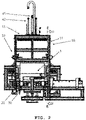
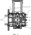
FIGS. 2 and3 are a front view and a plan view illustrating an overall configuration of the inverse system of the embodiment of the present disclosure, andFIG. 4 is a longitudinal cross-section view taken along line B-B ofFIG. 2 . -
FIG. 5 is a perspective view illustrating only a rotary device and a main frame in the inverse system of the embodiment of the present disclosure. -
FIG. 6 is a view illustrating only the rotary device and the main frame in the inverse system of the embodiment of the present disclosure as inFIG. 5 , and is a longitudinal cross-section view taken along line C-C ofFIG. 4 . -
FIG. 7 is a view illustrating only parts of the configuration of the rotary device illustrated inFIGS. 5 and6 . -
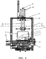
FIGS. 8 to 10 are a perspective view, a front view, and a side view illustrating a state in which the rotary device holds the packing box in the inverse system of the embodiment of the present disclosure. - Hereinafter, as details for implementing the present disclosure, a configuration and an operation of a reversing system for packing boxes according to an embodiment of the present disclosure will be described with reference to the drawings.
- The reversing system of the present embodiment is configured to reverse an empty box after products are withdrawn from the packing box having the configuration illustrated in
FIG. 1 . - After the adhesive tape coupling the first
upper surface panels packing box 1 in a state where the fourupper surface panels 2 to 5 are unfolded, thepacking box 1 is carried to the reversing system of the present embodiment by a conveyor belt or another carrying means - In the reversing system of the present embodiment, after the
packing box 1 is discharged from the reversing system of the present embodiment, and then the adhesive tape is cut such that the panels covering the lower surface are opened are folded, thepacking box 1 is stacked on another one, and is carried to another place for recycling. - First, an overall configuration of the reversing system of the present embodiment will be described with reference to
FIGS. 2 to 4 . - The reversing system of the present embodiment generally includes
third conveyors 90 that convey theempty packing box 1 from the position at which the products are withdrawn to a position adjacent to a position at which thepacking box 1 will be reversed,second conveyors 80 that are disposed perpendicular to thethird conveyors 90 and convey the reversedpacking box 1 to a position at which the panels of the lower surface are opened,first conveyors 70 that are disposed between thesecond conveyors 80 so as to be perpendicular to thesecond conveyors 80 and place thepacking box 1 conveyed by thethird conveyors 90 at a reversed position, aturning device 30 that holds, rotates, and reverses thepacking box 1 that is disposed at the reversed position by thefirst conveyors 70, first andsecond stoppers packing box 1 to be disposed at the reversed position, and amain frame 10 at which theturning device 30, thestoppers third conveyors 70 to 90 are installed. - The
main frame 10 may be made up of several frames configured independently of one another. Either an opening system of thepacking box 1 or a withdrawing system for withdrawing the products from the packing box 1may be disposed in thismain frame 10 in addition to the reversing system of the present embodiment. - Hereinafter, for the sake of convenience, the
main frame 10 is treated as a single element, and is disposed at positions different from each other. The frames belonging to themain frames 10 are referred to as the main frames, and are indicated by the same reference number. - First, a configuration of the
turning device 30 will be described with reference toFIGS. 5 to 7 . - The turning
device 30 holds and rotates thepacking box 1 disposed at the reversed position by the first andthird conveyors - Conveyor belts of the first to
third conveyors 70 to 90 are disposed on the same plane that is approximately parallel to the ground, and theturning device 30 is installed at a portion extending upwardly from this plane at themain frame 10. - The
main frame 10 includes fourvertical channels 11 extending vertically and ahorizontal channel 12 extending horizontally between upper ends of thevertical channels 11. A space enclosed by thevertical channels 11 and thehorizontal channel 12 form a reversing place in which thepacking box 1 is reversed. Components of theturning device 30 are coupled to or suspended from thehorizontal channel 12. - The turning
device 30 includesmovable frames horizontal channel 12 and configured to be movable upwardly and downwardly. - A vertically actuatable
pneumatic cylinder 41 and four vertically extendinglinear guides 42 are coupled to thehorizontal channels 12. Afirst frame 31 extending in parallel with a rotation axis (A ofFIG. 7 ) serving as the rotation center of thepacking box 1, and a pair ofsecond frames 32 extending in a vertical direction, are provided on a leading end of thepneumatic cylinder 41 and leading ends of the linear guides 42. - According to this configuration, when the
pneumatic cylinder 41 is driven upwardly and downwardly, the first frame 31and thesecond frames 32 are guided by thelinear guides 42, and are actuated in the vertical direction. -
Linear actuators 43 including thepneumatic cylinder 41 and thelinear guides 42 are provided at opposite ends of thefirst frame 31. Thelinear actuators 43 are driven in an extending direction of thefirst frame 31, i.e. in a direction of the rotation axis A, and upper ends of thesecond frames 32 are coupled to leading ends of thelinear actuators 43. - According to this configuration, when the
linear actuators 43 are driven, thesecond frames 32 are actuated in a direction as the same as or opposite to each other. -
Rotation driving motors 44 are coupled to lower ends of the respective second frames 32. Rotation shafts (not illustrated) of therotation driving motors 44 are disposed on the rotation axis A, and are fixedly coupled to the second frames 32. - Mounting
panels 33, on whichsuction members panels 33 are coupled to the rotation shafts of therotation driving motors 44 so as to be rotatable. - The two mounting
panels 33 are disposed to face each other, and a total of fivesuction members panels 33. The threefirst suction members 45 are disposed in parallel at an upper side of the rotation axis A, and the twosecond suction members 46 are disposed at a lower side of the rotation axis A. - The
suction members packing box 1 disposed between the mountingpanels 33. This will be described below, thefirst suction members 45 draw (or attract) theupper surface panels packing box 1, andsecond suction members 46 draw the sides of thepacking box 1. - Although not illustrated in
FIG. 6 , when referring toFIGS. 4 and5 , the mountingbracket 35 extend from the mountingpanels 33 at opposite sides of each of the mountingpanels 33, and bars 36 are coupled to leading ends of each of the mountingbrackets 35. - The
bars 36 extend from the leading ends of the mountingbrackets 35 in a direction parallel with the rotation axis A. The twobars 36 coupled to one of the mountingpanels 33 are separated in a width direction of thepacking box 1. - Next, configurations of the first to third conveyors and configurations of the
stoppers FIGS. 2 to 4 . - The
third conveyors 90 include two conveyor belts extending in parallel with each other. Thethird conveyors 90 extend from a position, at which anempty packing box 1 is disposed after the products are withdrawn, to a position at which thesecond conveyors 80 are disposed. - The
second conveyors 80 also include two conveyor belts extending in parallel with each other, and extending from the reversed position to a position at which the bottom surface of the reversedpacking box 1 is opened. - Since extending directions of the
third conveyors 90 and thesecond conveyors 80 are in perpendicular to each other, a direction in which thethird conveyors 90 introducing thepacking box 1 into the lower portion of theturning device 30 and a direction in which thesecond conveyors 80 draw the reversedpacking box 1 from the lower portion of theturning device 30 become perpendicular to each other. - Meanwhile, the
first conveyors 70 also include two conveyor belts extending in parallel with each other, the conveyor belts, and rollers (not illustrated) and motors (not illustrated) that turn and drive the conveyor belts constitute one assembly, and pneumatic cylinders and linear guides are provided as lifting devices (not illustrated) that vertically lift this assembly. - The
first conveyors 70 are disposed in a straight line with thethird conveyors 90, with respect to each other, and a pair of conveyor belts constituting thefirst conveyors 70 are disposed between a pair of conveyor belts constituting the second conveyor belts80. - According to this configuration, when introducing the
packing box 1 from the position at which the products are withdrawn to the lower portion of theturning device 30, i.e., the reversed position, thefirst conveyors 70 are raised to the upper sides of thesecond conveyors 80 by the lifting device (not illustrated), receive thepacking box 1 introduced by thethird conveyors 90, and cause the receivedpacking box 1 to be disposed at the reversed position. - When the
packing box 1 is disposed at the reversed position, thefirst conveyors 70 move down, and thepacking box 1 is supported by thesecond conveyors 80, and the reverse actuation caused by the turningdevice 30 is carried out. However, thefirst conveyors 70 may be disposed at the same height as thesecond conveyors 80 so as to support thepacking box 1 together with thesecond conveyors 80, and thefirst conveyors 70 may support thepacking box 1 during the reverse actuation caused by the turningdevice 30. - A
first stopper 21, which is disposed toward the direction opposite to the introducing direction of thepacking box 1, is disposed, and asecond stopper 22, which is disposed toward the direction in which thethird conveyors 90 draw thepacking box 1, is disposed. - The
packing box 1 is disposed at the reversed position by actuation control of the first tothird conveyors 70 to 90, but during the reverse actuation, the movement of thepacking box 1 is restricted to cause dislocation to be removed so that thesuction members bars 36 accurately hold thepacking box 1 during the reverse actuation. - The reverse actuation of the
packing box 1 according to the configuration as described above will be described with reference toFIGS. 8 to 10 . - Before the
packing box 1 is introduced, the turningdevice 30 is disposed at the raised position illustrated inFIG. 2 . Thepneumatic cylinder 41 is actuated in a contracted state, and raises the first andsecond frames suction members bars 36 are disposed at the raised position. The second frames 32 are adapted in a state of being separated from each other by the contracted actuations of thelinear actuators 43. - In this state, the
packing box 1 is introduced to the reversed position by the first andthird conveyors - When the
packing box 1 is safely disposed and supported by thesecond conveyors 80 or thefirst conveyors 70, thepneumatic cylinder 41 is enlarged and actuated, so that the first andsecond frames panels 33, thesuction members bars 36, which are attached to the frames, are also moved down. - The mounting
panels 33 and thebars 36 come into contact with the unfoldedupper surface panels 2 and 6 by lowering actuation, respectively. The lower end faces of the mountingpanels 33 are moved down while coming into contact with the two secondupper surface panels upper surface panels packing box 1. The respective bars 36 bring the firstupper surface panels packing box 1 while being in contact with the firstupper surface panels - When the lowering actuation is completed, the rotation shafts of the
rotation driving motors 44 are disposed at approximately geometric centers of the mutually facing sides of thepacking box 1. The geometric centers of the sides of thepacking box 1 are disposed on the rotation axis A. - The
linear actuators 43 are enlarged and actuated, so that the mountingpanels 33 are moved in the directions approximating each other. Accordingly, thesuction members panels 33 are brought in contact with thepacking box 1. - The
suction members 45 above the rotation axis A are in contact with the secondupper surface panels packing box 1, and thesuction members 46 below the rotation axis A are in contact with the sides of thepacking box 1. In this state, thesuction members packing box 1. - The
pneumatic cylinder 41 conducts the contraction and the actuation in a drawn state, the turningdevice 30 is raised, and thepacking box 1 is also raised in the drawn state. - After being raised from the
second conveyors 80 by a given distance, therotation driving motors 44 is rotated to turn the mountingpanels 33 by an angle of 180 degrees. Accordingly, thepacking box 1 is also turned and reversed by the angle of 180 degrees. - The
pneumatic cylinder 41 is again enlarged and actuated, so that the turningdevice 30 is moved downwardly, and thepacking box 1 is also moved downwardly in a drawn state, and is disposed above thesecond conveyors 80. Drawing actuations of thesuction members linear actuators 43 are contracted and actuated, so that the mountingpanels 33 are separated from each other. Accordingly, thepacking box 1 is disposed on thesecond conveyors 80 in the reversed state. Thesecond conveyors 80 are actuated and the products are withdrawn from the turning device. - In the
packing box 1 withdrawn from the reversing system of the present embodiment, the panels closing the bottom surface are opened and folded, and then are stacked by overlapping with another packing box. However, this actuation is not the actuation caused by the reversing system of the present embodiment, and thus illustrations and descriptions thereof will be omitted. - In the
packing box 1 in which the upper surface is opened and from which the products are withdrawn by the configuration and the actuation as described above, the reversed actuation by which the packing box is turned upside down is automatically conducted, and is carried for the post-treatment. - Hereinabove, the configuration and the operation of the reversing system for the packing box according to the embodiments of the present disclosure have been described, but various modifications and addition of elements are possible without departing from the claim without being limited to the foregoing embodiments.
Claims (6)
- A reversing system for reversing a packing box, an upper surface of which is opened, and from which products are withdrawn, such that a lower surface of the reversed empty packing box is disposed above, the reversing system comprising:a first conveyor configured to transfer an empty packing box, an upper surface of which is opened, from a withdrawn position at which products are withdrawn from a packing box to a reversed position at which a reversing operation is performed;a turning device configured to hold the packing box to be turned about a rotation axis horizontal to the ground, and to reverse the packing box; anda second conveyor configured to carry the reversed packing box to a position at which a work of opening the bottom surface is conducted,wherein the turning device holds two sides, facing each other, among sides of the packing box, and causes the packing pox to be turned and reversed using a portion between the holding locations of the two held sides as a rotation axis.
- The reversing system according to claim 1, wherein an upper surface panel covering the upper surface of the packing is provided on the upper surface of the packing, and introduced into the reversing system in an unfolded state when the products are withdrawn, and
the turning device comprises a movable frame moved upwardly and downwardly at the reversed position, a pair of suction units that are disposed at positions facing each other, respectively and having suction members that are actuated to move toward or away from each other and that draw the sides of the packing box at an approximating time, and bars configured to bring the upper surface panel of opened and unfolded state into close contact. - The reversing system according to claim 2, wherein the upper surface panel comprises a pair of first upper surface panels facing each other, and a pair of second upper surface panels that are disposed perpendicular to the first upper surface panels and face each other,the bars comprise a plurality of bars extending in parallel with the drawing directions of the suction members, each of the bars coming into contact with each of the first upper surface panels and bringing the first panels in contact with the packing box by the downward movement actuation, andeach of the suction units provided with the mounting panels to which the suction members are attached, and each of the mounting panels brings a leading end thereof in close contact with each of the second upper surface panels and brings the second upper surface panels into close contact with the side of the packing box by the downward movement actuation.
- The reversing system according to claim 3, wherein each of the suction units is provided with a plurality of suction members, and the suction members disposed on a side blow the turning axis come into contact with the side of the packing box, and the suction members disposed on a side above the turning axis come into contact with the second upper surface panels of the packing box.
- The reversing system according to claim 2, wherein the movable frame comprises a first frame that is moved upwardly and downwardly and extends in parallel with the turning axis of the packing box, and a pair of second frames that are disposed at opposite ends of the first frame and extend in a vertical direction,the second frames are coupled to the first frame to be moved in the turning axis direction of the packing box to move away from or toward each other, andeach of the suction units is provided with mounting panels to which the suction members are attached, and each of the second frames is provided with rotation driving motors using the rotation axis of the packing box that rotatably drives the mounting panel as the rotation shaft so as to rotate the mounting panels.
- The reversing system according to claim 1, wherein the second conveyor comprises a pair of conveyor belts extending from a reversed position to an opened position of a bottom surface of the packing box and parallel to each other,the first conveyor comprises a pair of conveyor belts disposed at the reversed position and extending perpendicular to the second conveyors between the conveyor belts of the second conveyor, andthe reversing system further comprising a third conveyor extending from an outer portion to a position adjacent to the second conveyor so as to be perpendicular to the second conveyor.
Applications Claiming Priority (2)
| Application Number | Priority Date | Filing Date | Title |
|---|---|---|---|
| KR1020200020682A KR102158643B1 (en) | 2020-02-19 | 2020-02-19 | System for Inverting a Packaging Box |
| PCT/KR2021/002133 WO2021167404A1 (en) | 2020-02-19 | 2021-02-19 | System for inverting packaging box |
Publications (2)
| Publication Number | Publication Date |
|---|---|
| EP4108606A1 true EP4108606A1 (en) | 2022-12-28 |
| EP4108606A4 EP4108606A4 (en) | 2023-12-13 |
Family
ID=72706680
Family Applications (1)
| Application Number | Title | Priority Date | Filing Date |
|---|---|---|---|
| EP21757023.3A Pending EP4108606A4 (en) | 2020-02-19 | 2021-02-19 | PACKING BOX TURNING SYSTEM |
Country Status (6)
| Country | Link |
|---|---|
| US (1) | US12103780B2 (en) |
| EP (1) | EP4108606A4 (en) |
| KR (1) | KR102158643B1 (en) |
| CN (1) | CN115485215B (en) |
| AU (1) | AU2021222857B2 (en) |
| WO (1) | WO2021167404A1 (en) |
Families Citing this family (22)
| Publication number | Priority date | Publication date | Assignee | Title |
|---|---|---|---|---|
| KR102158643B1 (en) | 2020-02-19 | 2020-09-22 | 씨제이제일제당(주) | System for Inverting a Packaging Box |
| USD1006618S1 (en) * | 2020-07-31 | 2023-12-05 | Pratt Corrugated Holdings, Inc. | Double-handle box |
| CN112124722A (en) * | 2020-09-28 | 2020-12-25 | 苏州大学附属第一医院 | Unpacking device for packing box |
| US11760531B2 (en) | 2020-10-09 | 2023-09-19 | Pratt Corrugated Holdings, Inc | Double-handle box |
| KR102274632B1 (en) | 2021-02-09 | 2021-07-07 | 주식회사 삼성칼라팩 | Apparatus for inverting a box stack |
| US11969967B2 (en) * | 2021-04-30 | 2024-04-30 | Packsize Llc | Systems and methods for folding and retaining box flaps |
| KR102383605B1 (en) * | 2021-08-10 | 2022-04-08 | 함영식 | Laminating eggbox panel separating apparatus |
| KR102710421B1 (en) * | 2021-08-27 | 2024-09-27 | 주식회사 비엠이앤씨 | Closure system for storage box |
| CN113715402B (en) * | 2021-09-28 | 2025-01-07 | 永发印务(四川)有限公司 | Fully automatic vertical bubble pressing system for packaging boxes |
| JP1719150S (en) * | 2021-09-28 | 2022-07-06 | document storage box | |
| CN114030859A (en) * | 2021-12-01 | 2022-02-11 | 国电联合动力技术(连云港)有限公司 | Fan main frame overturning device and method |
| KR102450540B1 (en) | 2022-03-08 | 2022-09-30 | 곽일남 | Box manufacturing equipment and system |
| IT202200004988A1 (en) * | 2022-03-15 | 2023-09-15 | Plusline S R L | Case packing machine. |
| CN114889880B (en) * | 2022-06-07 | 2024-04-09 | 泸州老窖股份有限公司 | A packaging method for a double-layer liquor packaging box |
| KR102540358B1 (en) * | 2022-10-04 | 2023-06-08 | 효원기계(주) | Stretch hood film wrapping machine |
| US20240308714A1 (en) * | 2023-03-15 | 2024-09-19 | Cornerstone Automation Systems, Llc | Automated decanting apparatus, a system including the apparatus, and a method of automatic decanting |
| CN116639468B (en) * | 2023-05-08 | 2023-12-08 | 株洲扬光新材料有限公司 | Metal surface sand blasting equipment and process |
| CN119370422B (en) * | 2023-07-27 | 2025-10-24 | 上海烟草机械有限责任公司 | A horizontal pre-pressing and packing device for tobacco strip production |
| CN116873315B (en) * | 2023-08-18 | 2025-12-26 | 黄冈市津志家电科技有限公司 | A device for mounting and gluing a housing |
| CN117302627B (en) * | 2023-11-29 | 2024-03-22 | 晋中弘旭盛发保温材料有限公司 | Packing device and packing method for plastic foam boxes |
| CN119038134B (en) * | 2024-10-31 | 2025-01-03 | 深圳市汇鼎智能制造技术有限公司 | Flipping fixture, flipping device and battery cell transfer production line |
| CN119262850B (en) * | 2024-12-12 | 2025-02-28 | 合肥浩普智能装备科技有限公司 | Magnetic suspension type ladle reversing conveyor |
Family Cites Families (22)
| Publication number | Priority date | Publication date | Assignee | Title |
|---|---|---|---|---|
| US2324401A (en) * | 1941-05-01 | 1943-07-13 | Standard Knapp Corp | Case sealing machine |
| US4232782A (en) | 1978-11-03 | 1980-11-11 | Shinko Kiko Co., Ltd. | Continuous conveyance system |
| DE3320459C2 (en) * | 1983-06-07 | 1986-11-13 | B.A.T. Cigaretten-Fabriken Gmbh, 2000 Hamburg | Device for removing a tobacco compact from a tobacco box |
| US4988255A (en) * | 1989-02-22 | 1991-01-29 | The Upjohn Company | Unpackaging machine |
| US5445590A (en) * | 1993-02-12 | 1995-08-29 | Douglas Machine Limited Liability Company | Collapsed, tubular carton erecting apparatus |
| US5558614A (en) * | 1993-02-12 | 1996-09-24 | Douglas Machine Limited Liability Company | Tubular carton opening, presenting, and closing apparatus |
| JP3477232B2 (en) * | 1993-11-30 | 2003-12-10 | 三菱重工業株式会社 | Waste paper transport box reversing machine |
| JPH0912133A (en) | 1995-06-28 | 1997-01-14 | Japan Tobacco Inc | Box reversing device |
| JPH1191746A (en) * | 1997-09-19 | 1999-04-06 | Snow Brand Milk Prod Co Ltd | Unsealing apparatus for packaging box |
| US6226965B1 (en) * | 1999-12-08 | 2001-05-08 | Belcor Industries Inc | Inline case sealing system |
| JP4491642B2 (en) * | 2003-07-29 | 2010-06-30 | 月島機械株式会社 | Processing method and processing apparatus for contents of box |
| KR100889818B1 (en) * | 2007-04-02 | 2009-03-20 | 삼성전자주식회사 | Packing box |
| KR101527654B1 (en) | 2013-12-02 | 2015-06-17 | 유하정판 주식회사 | A packing box |
| KR101554009B1 (en) | 2014-02-17 | 2015-09-17 | 주식회사크라운제과 | Display and drawing slot structure of the packingbox for stick Cake goods |
| CN104444283B (en) * | 2014-10-20 | 2017-01-18 | 河南省新斗彩印刷有限公司 | Automatic turning method for automatic packaging line finished product box |
| CN109677720B (en) * | 2017-10-26 | 2024-07-09 | 楚天科技股份有限公司 | Intelligent unpacking machine |
| JP7164620B2 (en) * | 2017-11-27 | 2022-11-01 | ランパク コーポレーション | Systems and methods for optimizing shipping box height |
| KR102023408B1 (en) * | 2017-12-19 | 2019-11-04 | 세방전지(주) | An automation system for assembling a packaging box and a method for operating the same |
| CN107954039A (en) * | 2017-12-24 | 2018-04-24 | 三只松鼠股份有限公司 | A kind of Auto-unboxing feeding production line |
| CN209754955U (en) * | 2019-01-21 | 2019-12-10 | 浙江精典数控设备有限公司 | Clamping and overturning mechanism |
| CN110654829A (en) * | 2019-09-23 | 2020-01-07 | 上海秦德物流设备有限公司 | Rapid automatic overturning machine for feed box line |
| KR102158643B1 (en) * | 2020-02-19 | 2020-09-22 | 씨제이제일제당(주) | System for Inverting a Packaging Box |
-
2020
- 2020-02-19 KR KR1020200020682A patent/KR102158643B1/en active Active
-
2021
- 2021-02-19 US US17/801,201 patent/US12103780B2/en active Active
- 2021-02-19 WO PCT/KR2021/002133 patent/WO2021167404A1/en not_active Ceased
- 2021-02-19 CN CN202180024043.1A patent/CN115485215B/en active Active
- 2021-02-19 AU AU2021222857A patent/AU2021222857B2/en active Active
- 2021-02-19 EP EP21757023.3A patent/EP4108606A4/en active Pending
Also Published As
| Publication number | Publication date |
|---|---|
| WO2021167404A1 (en) | 2021-08-26 |
| US20230075513A1 (en) | 2023-03-09 |
| CN115485215A (en) | 2022-12-16 |
| US12103780B2 (en) | 2024-10-01 |
| KR102158643B1 (en) | 2020-09-22 |
| AU2021222857B2 (en) | 2024-10-10 |
| CN115485215B (en) | 2025-08-26 |
| EP4108606A4 (en) | 2023-12-13 |
| AU2021222857A1 (en) | 2022-10-06 |
Similar Documents
| Publication | Publication Date | Title |
|---|---|---|
| US12103780B2 (en) | System for inverting packaging box | |
| US12110145B2 (en) | Opening system of packaging box | |
| CN115485200B (en) | Packing box folding system | |
| EP4108605A1 (en) | Arrangement system for arranging item drawn out from packing box | |
| KR102097888B1 (en) | Box packing apparatus | |
| KR20170054147A (en) | Assembly apparatus of a folded box | |
| US20110076126A1 (en) | Device and Method for Palletizing Items | |
| CN109178460A (en) | A kind of logistics carton automatic packaging equipment and label sticking machine | |
| KR101199003B1 (en) | Apparatus for taping long type box | |
| US12227376B2 (en) | Withdrawal system for withdrawing article from packaging box | |
| JPH07257520A (en) | Folding box opening mechanism | |
| US5255491A (en) | Method and apparatus for applying bands to crates | |
| US5246096A (en) | Rotate/translate conveyor module | |
| CN114715481A (en) | Cover clamping mechanism and packaging box finishing machine | |
| CN114715483B (en) | Lower plugging operating mechanism and packing box finishing machine | |
| CN222098169U (en) | A palletizing and packaging conveyor line | |
| US20260028145A1 (en) | Apparatus for boxing roll packed mattress | |
| BE1028763B1 (en) | A SYSTEM AND A PROCEDURE FOR ASSEMBLING A PACKAGING | |
| JPH09249207A (en) | Article filling device into carton | |
| JPH09240621A (en) | Cartom piling apparatus | |
| KR20250037915A (en) | Box carton supply equipment and box carton supply method using the same | |
| JP2593480Y2 (en) | Transfer device | |
| CN114671089A (en) | Packaging bag filling system | |
| CN114701700A (en) | Packaging bag opening unit and packaging bag filling system | |
| KR20110000163A (en) | Automatic packaging device and automatic packaging method using the same |
Legal Events
| Date | Code | Title | Description |
|---|---|---|---|
| STAA | Information on the status of an ep patent application or granted ep patent |
Free format text: STATUS: THE INTERNATIONAL PUBLICATION HAS BEEN MADE |
|
| PUAI | Public reference made under article 153(3) epc to a published international application that has entered the european phase |
Free format text: ORIGINAL CODE: 0009012 |
|
| STAA | Information on the status of an ep patent application or granted ep patent |
Free format text: STATUS: REQUEST FOR EXAMINATION WAS MADE |
|
| 17P | Request for examination filed |
Effective date: 20220909 |
|
| AK | Designated contracting states |
Kind code of ref document: A1 Designated state(s): AL AT BE BG CH CY CZ DE DK EE ES FI FR GB GR HR HU IE IS IT LI LT LU LV MC MK MT NL NO PL PT RO RS SE SI SK SM TR |
|
| DAV | Request for validation of the european patent (deleted) | ||
| DAX | Request for extension of the european patent (deleted) | ||
| P01 | Opt-out of the competence of the unified patent court (upc) registered |
Effective date: 20230606 |
|
| A4 | Supplementary search report drawn up and despatched |
Effective date: 20231113 |
|
| RIC1 | Information provided on ipc code assigned before grant |
Ipc: B65B 43/39 20060101ALI20231107BHEP Ipc: B65B 69/00 20060101ALI20231107BHEP Ipc: B65G 15/12 20060101ALI20231107BHEP Ipc: B65G 37/00 20060101ALI20231107BHEP Ipc: B65G 47/248 20060101AFI20231107BHEP |