EP4108601A1 - Packaging machine with protective guard - Google Patents
Packaging machine with protective guard Download PDFInfo
- Publication number
- EP4108601A1 EP4108601A1 EP21382563.1A EP21382563A EP4108601A1 EP 4108601 A1 EP4108601 A1 EP 4108601A1 EP 21382563 A EP21382563 A EP 21382563A EP 4108601 A1 EP4108601 A1 EP 4108601A1
- Authority
- EP
- European Patent Office
- Prior art keywords
- protective guard
- packaging machine
- protection position
- conveyor assembly
- machine according
- Prior art date
- Legal status (The legal status is an assumption and is not a legal conclusion. Google has not performed a legal analysis and makes no representation as to the accuracy of the status listed.)
- Granted
Links
Images
Classifications
-
- B—PERFORMING OPERATIONS; TRANSPORTING
- B65—CONVEYING; PACKING; STORING; HANDLING THIN OR FILAMENTARY MATERIAL
- B65G—TRANSPORT OR STORAGE DEVICES, e.g. CONVEYORS FOR LOADING OR TIPPING, SHOP CONVEYOR SYSTEMS OR PNEUMATIC TUBE CONVEYORS
- B65G21/00—Supporting or protective framework or housings for endless load-carriers or traction elements of belt or chain conveyors
-
- B—PERFORMING OPERATIONS; TRANSPORTING
- B65—CONVEYING; PACKING; STORING; HANDLING THIN OR FILAMENTARY MATERIAL
- B65B—MACHINES, APPARATUS OR DEVICES FOR, OR METHODS OF, PACKAGING ARTICLES OR MATERIALS; UNPACKING
- B65B57/00—Automatic control, checking, warning, or safety devices
- B65B57/005—Safety-devices
-
- B—PERFORMING OPERATIONS; TRANSPORTING
- B65—CONVEYING; PACKING; STORING; HANDLING THIN OR FILAMENTARY MATERIAL
- B65G—TRANSPORT OR STORAGE DEVICES, e.g. CONVEYORS FOR LOADING OR TIPPING, SHOP CONVEYOR SYSTEMS OR PNEUMATIC TUBE CONVEYORS
- B65G43/00—Control devices, e.g. for safety, warning or fault-correcting
- B65G43/02—Control devices, e.g. for safety, warning or fault-correcting detecting dangerous physical condition of load carriers, e.g. for interrupting the drive in the event of overheating
-
- F—MECHANICAL ENGINEERING; LIGHTING; HEATING; WEAPONS; BLASTING
- F16—ENGINEERING ELEMENTS AND UNITS; GENERAL MEASURES FOR PRODUCING AND MAINTAINING EFFECTIVE FUNCTIONING OF MACHINES OR INSTALLATIONS; THERMAL INSULATION IN GENERAL
- F16P—SAFETY DEVICES IN GENERAL; SAFETY DEVICES FOR PRESSES
- F16P1/00—Safety devices independent of the control and operation of any machine
- F16P1/005—Guards for rolls in calendering or other roll machines, e.g. nip guards, finger guards
-
- B—PERFORMING OPERATIONS; TRANSPORTING
- B65—CONVEYING; PACKING; STORING; HANDLING THIN OR FILAMENTARY MATERIAL
- B65B—MACHINES, APPARATUS OR DEVICES FOR, OR METHODS OF, PACKAGING ARTICLES OR MATERIALS; UNPACKING
- B65B43/00—Forming, feeding, opening or setting-up containers or receptacles in association with packaging
- B65B43/42—Feeding or positioning bags, boxes, or cartons in the distended, opened, or set-up state; Feeding preformed rigid containers, e.g. tins, capsules, glass tubes, glasses, to the packaging position; Locating containers or receptacles at the filling position; Supporting containers or receptacles during the filling operation
- B65B43/52—Feeding or positioning bags, boxes, or cartons in the distended, opened, or set-up state; Feeding preformed rigid containers, e.g. tins, capsules, glass tubes, glasses, to the packaging position; Locating containers or receptacles at the filling position; Supporting containers or receptacles during the filling operation using roller-ways or endless conveyors
-
- B—PERFORMING OPERATIONS; TRANSPORTING
- B65—CONVEYING; PACKING; STORING; HANDLING THIN OR FILAMENTARY MATERIAL
- B65B—MACHINES, APPARATUS OR DEVICES FOR, OR METHODS OF, PACKAGING ARTICLES OR MATERIALS; UNPACKING
- B65B59/00—Arrangements to enable machines to handle articles of different sizes, to produce packages of different sizes, to vary the contents of packages, to handle different types of packaging material, or to give access for cleaning or maintenance purposes
- B65B59/04—Machines constructed with readily-detachable units or assemblies, e.g. to facilitate maintenance
-
- B—PERFORMING OPERATIONS; TRANSPORTING
- B65—CONVEYING; PACKING; STORING; HANDLING THIN OR FILAMENTARY MATERIAL
- B65G—TRANSPORT OR STORAGE DEVICES, e.g. CONVEYORS FOR LOADING OR TIPPING, SHOP CONVEYOR SYSTEMS OR PNEUMATIC TUBE CONVEYORS
- B65G2207/00—Indexing codes relating to constructional details, configuration and additional features of a handling device, e.g. Conveyors
- B65G2207/40—Safety features of loads, equipment or persons
Definitions
- the invention relates to packaging machines.
- the invention relates to operational safety of packaging machines.
- thermoforming packaging machine with a forming station for forming depressions for the products to be packaged in a film web.
- a protective cover is provided to prevent a user from reaching into a protected space below the protective cover.
- the protective cover is a metal sheet part supported at a cover of the forming station with a pivotable connection.
- the pivotable connection allows the protective cover to pivot around a horizontal pivot axis extending perpendicular to the transport direction of the packaging machine.
- the protective cover may be opened by pivoting the protective cover about the pivot axis to allow access to the protected space.
- a sensor is provided to detect whether the protective cover is in its closed position. If the protective cover is not in its closed position, operation of the packaging machine is interrupted.
- a packaging machine comprising a controller and a conveyor assembly.
- the conveyor assembly is configured to convey packages along a production direction.
- the conveyor assembly comprises an endless circulation device.
- the endless circulation device is configured to be redirected about a return axis.
- the packaging machine further comprises a first protective guard.
- the first protective guard is movably provided in a first protection position.
- the first protective guard is curved around the return axis.
- the first protective guard By being curved around the return axis, the first protective guard provides protection against a user reaching towards the return axis, which may lead to injury due to moving parts of the conveyor assembly, for example. Due to its curvature, the first protective guard may prevent a user from reaching towards the return axis from an increased angular range. Further, a dimension of the first protective guard along the production direction may be reduced as compared to systems having non-curved protective guard, while maintaining at least the same level of protection.
- the first protective guard As the first protective guard is movably provided in the first protection position, the first protective guard may be moved out of the first protection positon, in particular to allow access to the return axis or the conveyor assembly, for example for maintenance purposes. Due to being movably provided in the first protection position, the first protective guard may move out of the first protection position, if the first protective guard is engaged by a hand of the user or by another object. This may prevent the hand of the user or the other object from being caught between the first protective guard and further parts of the packaging machine, such as parts of the conveyor assembly, for example. In particular, if a hand of a user or another object is pushed or pulled into the first protective guard by the conveyor assembly, the first protective guard may move along to prevent the hand or the other object from being caught and damaged between the first protective guard and the conveyor assembly.
- the first protective guard may be movable between the first protection position and a first open position.
- the first protective guard may be curved around the return axis at least in the first protection position.
- the first protective guard may be curved around the return axis in the first protection position and in the first open position.
- the force provided due to operation of the conveyor assembly may be sufficient to move the first protective guard out of the first protection position.
- the packaging machine may optionally comprise restoration element configured to automatically return the first protective guard into the first protection position.
- the restoration element may preload the first protective guard into the first protection position.
- the restoration element may, for example, comprise a spring.
- the first protective guard may be configured to be rotated.
- the first protective guard may be configured rotated out of the first protection position.
- the first protective guard may be configured to be rotated between the first protection position and the first open position.
- the first protective guard may be configured to be moved by rotational movement, but not by translational movement.
- the first protective guard may be configured to be moved by rotational movement and by translational movement. Rotating the first protective guard may take up less space along the production direction than moving the first protective guard (purely) by translational movement.
- the first protective guard may be configured to be rotated about the returned axis, in particular out of the first protection position or between the first protection position and the first open position. Movement of the first protective guard by rotation about the return axis may only require a limited amount of space around the return axis.
- the first protective guard may be fixed to the packaging machine, in particular to a machine frame of the packaging machine.
- the first protective guard may not be removable from the packaging machine without tools. This may reduce the likelihood of manipulation of the packaging machine by removal of safety features.
- the first protective guard may extend in parallel to the return axis.
- the first protective guard may extend coaxially with the return axis.
- the first protective guard and the return axis may be concentric.
- the first protective guard may cover an angle of at least 90 degrees, or at least 100 degrees, or at least 120 degrees, or at least 150 degrees, or at least 180 degrees around the return axis. By covering a significant angle around the return axis, the region around the return axis may be effectively protected.
- the first protective guard may cover an angle of no more than 270 degrees, or no more than 210 degrees, or no more than 180 degrees, or no more than 150 degrees, or no more than 90 degrees around the return axis. Limiting the angle covered by the protective guard may reduce the likelihood of interference of the first protective guard with operation of the conveyor assembly.
- a lateral direction of the packaging machine may be a horizontal direction perpendicular to the production direction.
- a main extension direction of the first protective guard may be parallel to the lateral direction.
- the first protective guard may extend along the lateral direction by at least 20 cm, or at least 30 cm, or at least 40 cm, or at least 50 cm, or at least 60 cm, or at least 80 cm, or at least 100 cm, or at least 120 cm.
- the first protective guard may comprise a concave surface facing the return axis.
- the concave surface may be a continuously curved surface.
- the concave surface may be provided by multiple plane sub-surfaces that are arranged at an angle with respect to each other.
- a cross-section of the first protective guard in a sectional plane perpendicular to the lateral direction of the packaging machine may be the same for each position along the lateral direction.
- the endless circulation device may comprise a first chain and a second chain.
- the first chain may be configured to circulate on a first lateral side of the packaging machine.
- the second chain may be configured to circulate on a second lateral side of the packaging machine.
- the first chain and the second chain may be redirected about the return axis.
- the first chain and the second chain may be driven by a drive unit of the conveyor assembly.
- the first chain and the second chain may circulate in a synchronized manner.
- the first chain and the second chain may circulate to convey the packages along the production direction.
- the first chain and the second chain may comprise clamping elements.
- the clamping elements may be configured to grip a film web for conveying the film web along the production direction.
- the film web may be a lower film web of a thermoforming packaging machine.
- the endless circulation device may comprise a plurality of lateral rods.
- Each lateral rod may comprise a first end fixed to the first chain and a second end fixed to the second chain.
- the lateral rods may be configured to be moved by synchronous circulation of the first chain and the second chain.
- the lateral rods may be configured to convey packages, in particular trays, along the production direction.
- the packaging machine may comprise a first sensor.
- the first sensor may be configured to detect when the first protective guard moves out of the first protection position.
- the controller may be configured to prevent operation of the conveyor assembly in response to a detection of the first protective guard moving out of the first protection position. For example, operation of the conveyor assembly may be prevented, when the first protective guard is moved out of the first protection position by an object that is caught between the first protective guard and the conveyor assembly, thus preventing damage to the object and/or the packaging machine. Operation of the conveyor assembly may be prevented when the first protective guard is not in the first protection position due to being removed from the packaging machine or due to malfunction, thus preventing operation of the conveyor assembly under unsafe conditions.
- the controller may also prevent operation of other parts of the packaging machine in response to a detection of the first protective guard moving out of the first protection position.
- the controller may, for example, be configured to prevent operation of the packaging machine in its entirety in response to a detection of the first protective guard moving out of the first protection position.
- the packaging machine may further comprise a second protective guard.
- the second protective guard may be movably provided in a second protection position.
- the second protective guard may be configured to be moved by both a translational movement and a rotational movement. Being movable by both a translational movement and a rotational movement may allow the second protective guard to move in response to objects being caught at different positions in the packaging machine.
- the different modes of movement that are possible for the second protective guard may allow the second protective guard to effectively move to prevent an object being caught between the second protective guard and another part of the packaging machine, in particular a moving part of the packaging machine, such as the conveyor assembly.
- the second protective guard may be configured to be moved by a translational movement and a rotational movement at the same time.
- the translational part of a movement of the second protective guard out of the second protection position may be a translational movement having a downward component, in particular a vertical downward component.
- the rotational part of a movement of the second protective guard out of the second protection position may comprise a rotation about an axis extending in a lateral direction of the packaging machine.
- the packaging machine may further comprise a holding assembly.
- the holding assembly may be configured to apply a holding force to the second protective guard.
- the holding force may be sufficient to hold the second protective guard in the second protection position during normal operation of the packaging machine.
- the holding force may be small enough to allow the second protective guard to be manually moved out of the second protection position.
- the packaging machine may further comprise a second sensor.
- the second sensor may be configured to detect when the second protective guard moves out of the second protection position.
- the controller may be configured to prevent operation of the conveyor assembly in response to a detection of the second protective guard moving out of the second protection position.
- the controller may be configured to prevent operation of further parts of the packaging machine, or of the packaging in its entirety, in response a detection of the second protective guard moving out of the second protection position.
- the second protective guard may be provided at an infeed end or at an outfeed end of the conveyor assembly.
- the second protective guard may be provided upstream of the return axis, or downstream of the return axis with respect to the production direction.
- a distance between the return axis and the second protective guard may be less than 10 cm, or less than 5 cm, or less than 3 cm, or less than 2 cm.
- the second protective guard may, in the second protection position, cover the return axis with respect to a horizontal direction along or against the production direction.
- the second protective guard may extend essentially vertically in the second protection position.
- the second protective guard may have a main extension direction parallel to the lateral direction.
- the second protective guard may be movably supported by engagement of a support pin in a slot to enable the translational movement and the rotational movement of the second protective guard.
- the second protective guard may be movably supported by engagement of a first support pin in a first slot at a first lateral side of the packaging machine, and by engagement of a second support pin in a second slot at a second lateral side of the packaging machine.
- the support pin (or the first support pin and the second support pin, respectively) may be provided in an upper position in the slot (or in the first slot or the second slot, respectively).
- a position of the support pin (or the first support pin and the second support pin) may change to a downward position in the slot (or in the first slot and the second slot, respectively). This may happen by movement of the pin, or by movement of the slot.
- the support pin may be provided at the second protective guard and the slot may be fixed with respect to a machine frame of the packaging machine.
- the slot may be provided at the second protective guard and the support pin may be fixed with respect to a machine frame of the packaging machine.
- the packaging machine may comprise a sealing station for sealing packages.
- the conveyor assembly may be configured to convey the packages for sealing to the sealing station, or may be configured to convey sealed packages away from the sealing station.
- the conveyor assembly may be configured to convey the packages further downstream of the sealing station, or further upstream of the sealing station.
- the packaging machine may be a thermoforming packaging machine.
- the packaging machine may be a tray sealer.
- the packages conveyed by the conveyor assembly may be unsealed packages or sealed packages.
- the packages conveyed by the conveyor assembly may be incomplete.
- the packages conveyed by the conveyor assembly may be parts that will be, at a more downstream position of the packaging machine, reformed or otherwise treated and/or combined with other parts to form the final packages.
- the packages conveyed by the conveyor assembly may comprise unsealed trays or sealed trays.
- the packages conveyed by the conveyor assembly may be a lower film web of a thermoforming packaging machine.
- the invention provides a method for operating a packaging machine.
- the method comprises conveying packages along a production direction with a conveyor assembly comprising an endless circulation device that is redirected about a return axis. Access to a protection region of the conveyor assembly is protected with a first protective guard, while the first protective guard is in a first protection position.
- the first protective guard is rotated out of the first protection position about the return axis. A rotation of the first protective guard out of the first protection position is detected with a first sensor. Operation of the conveyor assembly is prevented in response to the detection of the rotation of the first protective guard out of the first protection position.
- the first protective guard may move out of the way to avoid pinching of an object, such as a hand of a user that has been caught between the first protective guard and a part of the packaging machine, such as the conveyor assembly.
- the first protective guard may be rotated about the return axis by an object, such as a hand of a user that has been caught between the first protective guard and a movable part of the packaging machine.
- the first protective guard may be rotated out of the first protection position about the return axis manually by a user to facilitate access to the return axis, for example for maintenance purposes.
- the rotating motion of the first protective guard may be implemented in a space efficient manner.
- the first protective guard may correspond to the first protective guard of the packaging machine according to the aspect previously described.
- the first protective guard may be curved around the return axis.
- the conveyor assembly may alternatingly move in a forward sense and a rearward sense.
- the conveyor assembly When moving in the forward sense, the conveyor assembly may convey packages along the production direction.
- the conveyor assembly When moving in the rearward sense, the conveyor assembly may disengage the packages.
- the conveyor assembly may correspond to the conveyor assembly of the packaging machine according to the aspect previously described.
- the conveyor assembly may comprise a plurality of lateral rods that push the packages along the production direction, when the conveyor assembly moves in a forward sense.
- the conveyor assembly may push packages into a sealing position inside a sealing station of the packaging machine via the lateral rods. Once the packages are in the sealing position, the lateral rods may be withdrawn by a movement of the conveyor assembly in a rearward sense to avoid that the lateral rods are in the way of the sealing process.
- Access to the protection region of the conveyor assembly may be protected with a second protective guard, while the second protective guard is in a second protection position.
- the second protective guard may be moved out of the second protection position by a combination of a rotational movement and a translational movement.
- a movement of the second protective guard out of the second protection position may be detected with a second sensor. Operation of the conveyor assembly may be prevented in response to a detection of the movement of the second protective guard out of the second protection position.
- the second protective guard may correspond to the second protective guard of the packaging machine according to the aspect previously described.
- packaging machine may be combined with or transferred to the other one of the packaging machine and the method for operating the packaging machine.
- packaging machine may be suitable for, designed for, and/or configured for carrying out the method.
- the method may be carried out using the packaging machine.
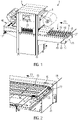
- Fig. 1 illustrates a packaging machine 1 according to an embodiment.
- the illustrated packaging machine 1 is of a type known as tray sealer.
- the invention could also be applied to packaging machines of other types, such as a thermoforming packaging machine, for example.
- the packaging machine 1 comprises a sealing station 3 for closing trays (packages) by sealing a top film 5 to the trays along a sealing seam surrounding an opening of the tray.
- the packaging machine 1 comprises an infeed section 7 with a conveyor assembly 9 for conveying the trays along a production direction 11 towards the sealing station 3 or into the sealing station 3. On the way to the sealing station 3, products may be inserted into the trays, for example while the trays are conveyed along the production direction 11 by the conveyor assembly 9.
- the conveyor assembly 9 comprises an endless circulation device for transporting the trays.
- the endless circulation device comprises first and second chains 13 circulating at opposing lateral sides of the packaging machine 1.
- Lateral rods 15 extend between the first and second chains 13 in parallel to a lateral direction, which is a horizontal direction perpendicular to the production direction 11.
- the conveyor assembly 9 further comprises a drive unit 17 (see Fig. 2 ) driving the first and second chains 13 in a synchronous manner.
- the first and second chains 13 and the lateral rods 15 are redirected about a return axis 19 during operation of the conveyor assembly 9.
- the return axis 19 extends in parallel to the lateral direction. In the illustrated embodiment, the return axis 19 is provided at an upstream end of the conveyor assembly 9.
- the packaging machine 1 comprises a controller 21.
- the controller 21 is configured to control operation of the sealing station 3 and operation of the conveyor assembly 9.
- the controller 21 controls the conveyor assembly 9 to intermittently convey the trays along the production direction 11.
- the conveyor assembly 9 first moves in a forward sense (by circulating anti-clockwise in Fig. 1 ) to push trays into the sealing station 3 by engagement with the lateral rods 15.
- the conveyor assembly 9 circulates in a rearward sense (clockwise in Fig. 1 ) to withdraw any laterals rod 15 from the sealing station 3.
- the sealing station 3 operates to seal the trays.
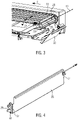
- a first protective guard 23 is curved around the return axis 19.
- the first protective guard 23 is shown in a first protection position.
- the first protective guard 23 prevents a user from reaching towards the return axis 19 from a certain angular range around the return axis 19.
- the first protective guard 23 may be moved out of the first protection position by rotation about the return axis 19.
- the first protective guard 23 may be guided for rotation about the return axis 19 in grooves provided in opposing side parts 27 of the machine frame 29 of the packaging machinel (see Fig. 1 ).
- a hand or another object that moves or is pushed against the first protective guard 23 in a direction opposite to the production direction 11 causes the first protective guard 23 to rotate about the return axis 19. This may prevent the hand or other object from being caught between the first protective guard 23 and the moving part of the packaging machine 1, in particular one of the lateral rods 15.
- a first sensor 31 schematically shown in Figs. 2 and 3 detects whether the first protective guard 23 is in the first protection position or not.
- the first sensor 31 is a magnetic sensor detecting whether a magnet 33 that is attached to the first protective guard 23 is in a position corresponding to the first protection position of the first protective guard 23.
- other types of sensors may be used, such as, for example, radar sensors or sensors based on one or more light barriers.
- the controller 21 shuts down operation of at least the conveyor assembly 9, or more preferably, operation of the entire packaging machine 1, for safety reasons.
- the packaging machine 1 further comprises an optional second protective guard 35.
- the second protective guard 35 may comprise a metal sheet extending along the lateral direction at a position upstream of the return axis 19.
- Fig. 2 shows a second protective guard 35 in a second protection position.
- Fig. 3 shows the second protective guard 35 in a second open position.
- the second protective guard 35 covers the return axis 19 with respect to the production direction 11.
- a distance between the return axis 19 and the second protective guard 35 is increased as compared to the second protection position.
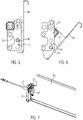
- Fig. 4 shows the second protective guard 35 together with two brackets 37.
- the brackets 37 are provided at opposing lateral sides of the second protective guard 35.
- the brackets 37 are fixedly attached to the machine frame 29 of the packaging machine 1 at opposing lateral sides of the packaging machine 1.
- the second protective guard 35 comprises support pins 39 protruding from the second protective guard 35 at opposing lateral ends of the second protective guard 35.
- Each one of the brackets 37 comprises a vertical slot 41 receiving a corresponding one of the support pins 39.
- the second protective guard 35 is fixed to the machine frame 29 of the packaging machine 1 via engagement of the support pins 39 in the slots 41.
- Fig. 5 shows the positioning of the second protective guard 35 with respect to the bracket 37 in the second protection position.
- the second protective guard 35 In the second protection position, the second protective guard 35 extends essentially vertically.
- the support pin 39 is provided in an upper position in the slot 41.
- Fig. 7 shows a holding assembly 43 applying a holding force between the bracket 37 and the second protective guard 35 to hold the second protective guard 35 in the second protection position.
- the holding assembly 43 comprises a plunger.
- the plunger may be provided at the bracket 37 and may engage into a recess or opening in the second protective guard 35.
- the plunger may be provided at the second protective guard 35 and may reach into a recess or opening in the bracket 37.
- the holding assembly 43 applies a holding force sufficient to hold the second protective guard 35 in the second protection position during normal operation of the packaging machine 1. However, when a hand or another object is pushed against the second protective guard 35, the holding force applied by the holding assembly 43 may be overcome to move the second protective guard 35 to the second open position.
- the second protective guard 35 is moved from the second protection position illustrated in Fig.5 into the second open position illustrated in Fig. 6 by a combination of a translational motion and a rotational motion. Both the rotational motion and the translational motion are enabled by a movement of the support pins 39 in the slots 41 of the brackets 37. To reach the second open position, the support pin 39 slides downward within the slot 41. Further, the second protective guard 35 rotates about an axis defined by the support pin 39, in particular such that an upper section of the second protective guard 35 rotates away from the conveyor assembly 9 or from the return axis 19.
- a second sensor 45 is provided to detect whether the second protective guard 35 is in the second protection position.
- the second sensor 45 comprises a magnetic sensor detecting whether a magnet 47 attached to the second protective guard 35 is present in a position corresponding to the second protection position of the second protective guard 35.
- Other types of sensors may be employed.
- the controller 21 prevents operation of at least the conveyor assembly 9, or preferably operation of the packaging machine 1 in its entirety, for safety reasons.
- the illustrated embodiment shows the first protective guard 23 and the second protective guard 35 at an infeed end of the conveyor assembly 7.
- one or both of the first protective guard 23 and the second protective guard 35 may be provided, for example, at a downstream end of an outfeed conveyor 49 of the packaging machine 1 (see Fig. 1 ) or at the infeed end or the outfeed end of any other conveyor of the packaging machine 1.
Landscapes
- Engineering & Computer Science (AREA)
- Mechanical Engineering (AREA)
- General Engineering & Computer Science (AREA)
- Auxiliary Devices For And Details Of Packaging Control (AREA)
Abstract
Description
- The invention relates to packaging machines. In particular, the invention relates to operational safety of packaging machines.
- It is known from practice to provide removable safety covers at packaging machines to prevent injury of operators or service personnel due to moving machine parts.
-
DE 10 2019 214 962 A1 describes a thermoforming packaging machine with a forming station for forming depressions for the products to be packaged in a film web. Directly downstream of the forming station, a protective cover is provided to prevent a user from reaching into a protected space below the protective cover. The protective cover is a metal sheet part supported at a cover of the forming station with a pivotable connection. The pivotable connection allows the protective cover to pivot around a horizontal pivot axis extending perpendicular to the transport direction of the packaging machine. The protective cover may be opened by pivoting the protective cover about the pivot axis to allow access to the protected space. A sensor is provided to detect whether the protective cover is in its closed position. If the protective cover is not in its closed position, operation of the packaging machine is interrupted. - It is an object of the present invention to provide an improved way of ensuring safe operation of a packaging machine.
- This object is achieved by the subject matter of claim 1 or the subject matter of
claim 13, respectively. The dependent claims indicate advantageous embodiments of the invention. - According to an aspect of the invention, a packaging machine is provided. The packaging machine comprises a controller and a conveyor assembly. The conveyor assembly is configured to convey packages along a production direction. The conveyor assembly comprises an endless circulation device. The endless circulation device is configured to be redirected about a return axis. The packaging machine further comprises a first protective guard. The first protective guard is movably provided in a first protection position. The first protective guard is curved around the return axis.
- By being curved around the return axis, the first protective guard provides protection against a user reaching towards the return axis, which may lead to injury due to moving parts of the conveyor assembly, for example. Due to its curvature, the first protective guard may prevent a user from reaching towards the return axis from an increased angular range. Further, a dimension of the first protective guard along the production direction may be reduced as compared to systems having non-curved protective guard, while maintaining at least the same level of protection.
- As the first protective guard is movably provided in the first protection position, the first protective guard may be moved out of the first protection positon, in particular to allow access to the return axis or the conveyor assembly, for example for maintenance purposes. Due to being movably provided in the first protection position, the first protective guard may move out of the first protection position, if the first protective guard is engaged by a hand of the user or by another object. This may prevent the hand of the user or the other object from being caught between the first protective guard and further parts of the packaging machine, such as parts of the conveyor assembly, for example. In particular, if a hand of a user or another object is pushed or pulled into the first protective guard by the conveyor assembly, the first protective guard may move along to prevent the hand or the other object from being caught and damaged between the first protective guard and the conveyor assembly.
- The first protective guard may be movable between the first protection position and a first open position. The first protective guard may be curved around the return axis at least in the first protection position. The first protective guard may be curved around the return axis in the first protection position and in the first open position.
- If an object is caught between the conveyor assembly and the first protective guard, the force provided due to operation of the conveyor assembly may be sufficient to move the first protective guard out of the first protection position.
- The packaging machine may optionally comprise restoration element configured to automatically return the first protective guard into the first protection position. The restoration element may preload the first protective guard into the first protection position. The restoration element may, for example, comprise a spring.
- The first protective guard may be configured to be rotated. The first protective guard may be configured rotated out of the first protection position. The first protective guard may be configured to be rotated between the first protection position and the first open position. The first protective guard may be configured to be moved by rotational movement, but not by translational movement. The first protective guard may be configured to be moved by rotational movement and by translational movement. Rotating the first protective guard may take up less space along the production direction than moving the first protective guard (purely) by translational movement.
- The first protective guard may be configured to be rotated about the returned axis, in particular out of the first protection position or between the first protection position and the first open position. Movement of the first protective guard by rotation about the return axis may only require a limited amount of space around the return axis.
- The first protective guard may be fixed to the packaging machine, in particular to a machine frame of the packaging machine. The first protective guard may not be removable from the packaging machine without tools. This may reduce the likelihood of manipulation of the packaging machine by removal of safety features.
- The first protective guard may extend in parallel to the return axis.
- The first protective guard may extend coaxially with the return axis. The first protective guard and the return axis may be concentric.
- The first protective guard may cover an angle of at least 90 degrees, or at least 100 degrees, or at least 120 degrees, or at least 150 degrees, or at least 180 degrees around the return axis. By covering a significant angle around the return axis, the region around the return axis may be effectively protected. The first protective guard may cover an angle of no more than 270 degrees, or no more than 210 degrees, or no more than 180 degrees, or no more than 150 degrees, or no more than 90 degrees around the return axis. Limiting the angle covered by the protective guard may reduce the likelihood of interference of the first protective guard with operation of the conveyor assembly.
- A lateral direction of the packaging machine may be a horizontal direction perpendicular to the production direction.
- A main extension direction of the first protective guard may be parallel to the lateral direction. The first protective guard may extend along the lateral direction by at least 20 cm, or at least 30 cm, or at least 40 cm, or at least 50 cm, or at least 60 cm, or at least 80 cm, or at least 100 cm, or at least 120 cm.
- The first protective guard may comprise a concave surface facing the return axis. The concave surface may be a continuously curved surface. Alternatively, the concave surface may be provided by multiple plane sub-surfaces that are arranged at an angle with respect to each other. A cross-section of the first protective guard in a sectional plane perpendicular to the lateral direction of the packaging machine may be the same for each position along the lateral direction.
- The endless circulation device may comprise a first chain and a second chain. The first chain may be configured to circulate on a first lateral side of the packaging machine. The second chain may be configured to circulate on a second lateral side of the packaging machine. The first chain and the second chain may be redirected about the return axis. The first chain and the second chain may be driven by a drive unit of the conveyor assembly. The first chain and the second chain may circulate in a synchronized manner. The first chain and the second chain may circulate to convey the packages along the production direction.
- The first chain and the second chain may comprise clamping elements. The clamping elements may be configured to grip a film web for conveying the film web along the production direction. The film web may be a lower film web of a thermoforming packaging machine.
- The endless circulation device may comprise a plurality of lateral rods. Each lateral rod may comprise a first end fixed to the first chain and a second end fixed to the second chain. The lateral rods may be configured to be moved by synchronous circulation of the first chain and the second chain. The lateral rods may be configured to convey packages, in particular trays, along the production direction.
- The packaging machine may comprise a first sensor. The first sensor may be configured to detect when the first protective guard moves out of the first protection position. The controller may be configured to prevent operation of the conveyor assembly in response to a detection of the first protective guard moving out of the first protection position. For example, operation of the conveyor assembly may be prevented, when the first protective guard is moved out of the first protection position by an object that is caught between the first protective guard and the conveyor assembly, thus preventing damage to the object and/or the packaging machine. Operation of the conveyor assembly may be prevented when the first protective guard is not in the first protection position due to being removed from the packaging machine or due to malfunction, thus preventing operation of the conveyor assembly under unsafe conditions. The controller may also prevent operation of other parts of the packaging machine in response to a detection of the first protective guard moving out of the first protection position. The controller may, for example, be configured to prevent operation of the packaging machine in its entirety in response to a detection of the first protective guard moving out of the first protection position.
- The packaging machine may further comprise a second protective guard. The second protective guard may be movably provided in a second protection position.
- The second protective guard may be configured to be moved by both a translational movement and a rotational movement. Being movable by both a translational movement and a rotational movement may allow the second protective guard to move in response to objects being caught at different positions in the packaging machine. The different modes of movement that are possible for the second protective guard may allow the second protective guard to effectively move to prevent an object being caught between the second protective guard and another part of the packaging machine, in particular a moving part of the packaging machine, such as the conveyor assembly.
- The second protective guard may be configured to be moved by a translational movement and a rotational movement at the same time.
- The translational part of a movement of the second protective guard out of the second protection position may be a translational movement having a downward component, in particular a vertical downward component.
- The rotational part of a movement of the second protective guard out of the second protection position may comprise a rotation about an axis extending in a lateral direction of the packaging machine.
- The packaging machine may further comprise a holding assembly. The holding assembly may be configured to apply a holding force to the second protective guard. The holding force may be sufficient to hold the second protective guard in the second protection position during normal operation of the packaging machine. The holding force may be small enough to allow the second protective guard to be manually moved out of the second protection position. When an object has been caught between the second protective guard and another part of the packaging machine, in particular a movable part of the packaging machine, such as a conveyor assembly, the second protective guard may, against the force applied by the holding assembly, be moved out of the second protection position.
- The packaging machine may further comprise a second sensor. The second sensor may be configured to detect when the second protective guard moves out of the second protection position. The controller may be configured to prevent operation of the conveyor assembly in response to a detection of the second protective guard moving out of the second protection position. The controller may be configured to prevent operation of further parts of the packaging machine, or of the packaging in its entirety, in response a detection of the second protective guard moving out of the second protection position.
- The second protective guard may be provided at an infeed end or at an outfeed end of the conveyor assembly.
- The second protective guard may be provided upstream of the return axis, or downstream of the return axis with respect to the production direction. A distance between the return axis and the second protective guard may be less than 10 cm, or less than 5 cm, or less than 3 cm, or less than 2 cm. The second protective guard may, in the second protection position, cover the return axis with respect to a horizontal direction along or against the production direction.
- The second protective guard may extend essentially vertically in the second protection position.
- The second protective guard may have a main extension direction parallel to the lateral direction.
- The second protective guard may be movably supported by engagement of a support pin in a slot to enable the translational movement and the rotational movement of the second protective guard. In particular, the second protective guard may be movably supported by engagement of a first support pin in a first slot at a first lateral side of the packaging machine, and by engagement of a second support pin in a second slot at a second lateral side of the packaging machine. When the second protective guard is in the second protection position, the support pin (or the first support pin and the second support pin, respectively) may be provided in an upper position in the slot (or in the first slot or the second slot, respectively). When the second protective guard moves out of the second protection position, a position of the support pin (or the first support pin and the second support pin) may change to a downward position in the slot (or in the first slot and the second slot, respectively). This may happen by movement of the pin, or by movement of the slot.
- The support pin may be provided at the second protective guard and the slot may be fixed with respect to a machine frame of the packaging machine. Alternatively, the slot may be provided at the second protective guard and the support pin may be fixed with respect to a machine frame of the packaging machine.
- The packaging machine may comprise a sealing station for sealing packages. The conveyor assembly may be configured to convey the packages for sealing to the sealing station, or may be configured to convey sealed packages away from the sealing station. The conveyor assembly may be configured to convey the packages further downstream of the sealing station, or further upstream of the sealing station.
- The packaging machine may be a thermoforming packaging machine. The packaging machine may be a tray sealer.
- The packages conveyed by the conveyor assembly may be unsealed packages or sealed packages. The packages conveyed by the conveyor assembly may be incomplete. The packages conveyed by the conveyor assembly may be parts that will be, at a more downstream position of the packaging machine, reformed or otherwise treated and/or combined with other parts to form the final packages. The packages conveyed by the conveyor assembly may comprise unsealed trays or sealed trays. The packages conveyed by the conveyor assembly may be a lower film web of a thermoforming packaging machine.
- According to a further aspect, the invention provides a method for operating a packaging machine. The method comprises conveying packages along a production direction with a conveyor assembly comprising an endless circulation device that is redirected about a return axis. Access to a protection region of the conveyor assembly is protected with a first protective guard, while the first protective guard is in a first protection position. The first protective guard is rotated out of the first protection position about the return axis. A rotation of the first protective guard out of the first protection position is detected with a first sensor. Operation of the conveyor assembly is prevented in response to the detection of the rotation of the first protective guard out of the first protection position.
- By rotating out of the first protection position about the return axis, the first protective guard may move out of the way to avoid pinching of an object, such as a hand of a user that has been caught between the first protective guard and a part of the packaging machine, such as the conveyor assembly. The first protective guard may be rotated about the return axis by an object, such as a hand of a user that has been caught between the first protective guard and a movable part of the packaging machine.
- The first protective guard may be rotated out of the first protection position about the return axis manually by a user to facilitate access to the return axis, for example for maintenance purposes.
- The rotating motion of the first protective guard may be implemented in a space efficient manner.
- The first protective guard may correspond to the first protective guard of the packaging machine according to the aspect previously described.
- The first protective guard may be curved around the return axis.
- The conveyor assembly may alternatingly move in a forward sense and a rearward sense. When moving in the forward sense, the conveyor assembly may convey packages along the production direction. When moving in the rearward sense, the conveyor assembly may disengage the packages.
- The conveyor assembly may correspond to the conveyor assembly of the packaging machine according to the aspect previously described. For example, the conveyor assembly may comprise a plurality of lateral rods that push the packages along the production direction, when the conveyor assembly moves in a forward sense. The conveyor assembly may push packages into a sealing position inside a sealing station of the packaging machine via the lateral rods. Once the packages are in the sealing position, the lateral rods may be withdrawn by a movement of the conveyor assembly in a rearward sense to avoid that the lateral rods are in the way of the sealing process.
- Access to the protection region of the conveyor assembly may be protected with a second protective guard, while the second protective guard is in a second protection position. The second protective guard may be moved out of the second protection position by a combination of a rotational movement and a translational movement. A movement of the second protective guard out of the second protection position may be detected with a second sensor. Operation of the conveyor assembly may be prevented in response to a detection of the movement of the second protective guard out of the second protection position.
- The second protective guard may correspond to the second protective guard of the packaging machine according to the aspect previously described.
- Features, explanations and advantages described in the context of the packaging machine or the method for operating the packaging machine may be combined with or transferred to the other one of the packaging machine and the method for operating the packaging machine. In particular, the packaging machine may be suitable for, designed for, and/or configured for carrying out the method. The method may be carried out using the packaging machine.
- In the following, embodiments are described with reference to the figures, whereby
-
Fig. 1 shows a schematic perspective view of a packaging machine according to an embodiment; -
Fig. 2 shows a schematic cut perspective view of an infeed conveyor section of the packaging machine with the second protective guard in the second protection position; -
Fig. 3 shows a schematic cut perspective view of the infeed conveyor section of the packaging machine with the second protective guard in the second open position; -
Fig. 4 shows a schematic perspective view of the second protective guard and corresponding holding brackets of the packaging machine according to the embodiment; -
Fig. 5 shows a schematic side view of the second protective guard in the second protection position; -
Fig. 6 shows a schematic side view of the second protective guard in the second open position; and -
Fig. 7 shows a schematic perspective view of the second protective guard seen from the side of the infeed conveyor. -
Fig. 1 illustrates a packaging machine 1 according to an embodiment. The illustrated packaging machine 1 is of a type known as tray sealer. However, the invention could also be applied to packaging machines of other types, such as a thermoforming packaging machine, for example. - In the illustrated embodiment, the packaging machine 1 comprises a sealing
station 3 for closing trays (packages) by sealing atop film 5 to the trays along a sealing seam surrounding an opening of the tray. - The packaging machine 1 comprises an
infeed section 7 with aconveyor assembly 9 for conveying the trays along aproduction direction 11 towards the sealingstation 3 or into the sealingstation 3. On the way to the sealingstation 3, products may be inserted into the trays, for example while the trays are conveyed along theproduction direction 11 by theconveyor assembly 9. - The
conveyor assembly 9 comprises an endless circulation device for transporting the trays. The endless circulation device comprises first andsecond chains 13 circulating at opposing lateral sides of the packaging machine 1.Lateral rods 15 extend between the first andsecond chains 13 in parallel to a lateral direction, which is a horizontal direction perpendicular to theproduction direction 11. Theconveyor assembly 9 further comprises a drive unit 17 (seeFig. 2 ) driving the first andsecond chains 13 in a synchronous manner. The first andsecond chains 13 and thelateral rods 15 are redirected about areturn axis 19 during operation of theconveyor assembly 9. Thereturn axis 19 extends in parallel to the lateral direction. In the illustrated embodiment, thereturn axis 19 is provided at an upstream end of theconveyor assembly 9. - The packaging machine 1 comprises a
controller 21. Thecontroller 21 is configured to control operation of the sealingstation 3 and operation of theconveyor assembly 9. In particular, thecontroller 21 controls theconveyor assembly 9 to intermittently convey the trays along theproduction direction 11. In a work cycle, theconveyor assembly 9 first moves in a forward sense (by circulating anti-clockwise inFig. 1 ) to push trays into the sealingstation 3 by engagement with thelateral rods 15. Once the trays are in place in the sealingstation 3, theconveyor assembly 9 circulates in a rearward sense (clockwise inFig. 1 ) to withdraw anylaterals rod 15 from the sealingstation 3. Subsequently, the sealingstation 3 operates to seal the trays. - As can best be seen in
Figs. 2 and3 , a firstprotective guard 23 is curved around thereturn axis 19. InFigs. 2 and3 , the firstprotective guard 23 is shown in a first protection position. The firstprotective guard 23 prevents a user from reaching towards thereturn axis 19 from a certain angular range around thereturn axis 19. As indicated byarrows 25 inFigs. 2 and3 , the firstprotective guard 23 may be moved out of the first protection position by rotation about thereturn axis 19. For example, the firstprotective guard 23 may be guided for rotation about thereturn axis 19 in grooves provided in opposingside parts 27 of themachine frame 29 of the packaging machinel (seeFig. 1 ). - A hand or another object that moves or is pushed against the first
protective guard 23 in a direction opposite to theproduction direction 11 causes the firstprotective guard 23 to rotate about thereturn axis 19. This may prevent the hand or other object from being caught between the firstprotective guard 23 and the moving part of the packaging machine 1, in particular one of thelateral rods 15. - A
first sensor 31 schematically shown inFigs. 2 and3 detects whether the firstprotective guard 23 is in the first protection position or not. In the illustrated embodiment, thefirst sensor 31 is a magnetic sensor detecting whether amagnet 33 that is attached to the firstprotective guard 23 is in a position corresponding to the first protection position of the firstprotective guard 23. Alternatively, other types of sensors may be used, such as, for example, radar sensors or sensors based on one or more light barriers. - When the
first sensor 31 detects the firstprotective guard 23 moving out of the first protection position (for example, by detecting that the firstprotective guard 23 is no longer in the first protection position), thecontroller 21 shuts down operation of at least theconveyor assembly 9, or more preferably, operation of the entire packaging machine 1, for safety reasons. - In the illustrated embodiment, the packaging machine 1 further comprises an optional second
protective guard 35. The secondprotective guard 35 may comprise a metal sheet extending along the lateral direction at a position upstream of thereturn axis 19. -
Fig. 2 shows a secondprotective guard 35 in a second protection position. -
Fig. 3 shows the secondprotective guard 35 in a second open position. In the second protection position, the secondprotective guard 35 covers thereturn axis 19 with respect to theproduction direction 11. In the second open position, a distance between thereturn axis 19 and the secondprotective guard 35 is increased as compared to the second protection position. -
Fig. 4 shows the secondprotective guard 35 together with twobrackets 37. Thebrackets 37 are provided at opposing lateral sides of the secondprotective guard 35. Thebrackets 37 are fixedly attached to themachine frame 29 of the packaging machine 1 at opposing lateral sides of the packaging machine 1. The secondprotective guard 35 comprises support pins 39 protruding from the secondprotective guard 35 at opposing lateral ends of the secondprotective guard 35. Each one of thebrackets 37 comprises avertical slot 41 receiving a corresponding one of the support pins 39. The secondprotective guard 35 is fixed to themachine frame 29 of the packaging machine 1 via engagement of the support pins 39 in theslots 41. -
Fig. 5 shows the positioning of the secondprotective guard 35 with respect to thebracket 37 in the second protection position. In the second protection position, the secondprotective guard 35 extends essentially vertically. Thesupport pin 39 is provided in an upper position in theslot 41. -
Fig. 7 shows a holdingassembly 43 applying a holding force between thebracket 37 and the secondprotective guard 35 to hold the secondprotective guard 35 in the second protection position. The holdingassembly 43 comprises a plunger. The plunger may be provided at thebracket 37 and may engage into a recess or opening in the secondprotective guard 35. Alternatively, the plunger may be provided at the secondprotective guard 35 and may reach into a recess or opening in thebracket 37. The holdingassembly 43 applies a holding force sufficient to hold the secondprotective guard 35 in the second protection position during normal operation of the packaging machine 1. However, when a hand or another object is pushed against the secondprotective guard 35, the holding force applied by the holdingassembly 43 may be overcome to move the secondprotective guard 35 to the second open position. - The second
protective guard 35 is moved from the second protection position illustrated inFig.5 into the second open position illustrated inFig. 6 by a combination of a translational motion and a rotational motion. Both the rotational motion and the translational motion are enabled by a movement of the support pins 39 in theslots 41 of thebrackets 37. To reach the second open position, thesupport pin 39 slides downward within theslot 41. Further, the secondprotective guard 35 rotates about an axis defined by thesupport pin 39, in particular such that an upper section of the secondprotective guard 35 rotates away from theconveyor assembly 9 or from thereturn axis 19. - As illustrated in
Fig. 7 , asecond sensor 45 is provided to detect whether the secondprotective guard 35 is in the second protection position. Preferably, thesecond sensor 45 comprises a magnetic sensor detecting whether amagnet 47 attached to the secondprotective guard 35 is present in a position corresponding to the second protection position of the secondprotective guard 35. Other types of sensors may be employed. - When the
second sensor 45 detects the secondprotective guard 35 moving out of the second protection position (for example, by detecting that the secondprotective guard 35 is no longer in the second protection position), thecontroller 21 prevents operation of at least theconveyor assembly 9, or preferably operation of the packaging machine 1 in its entirety, for safety reasons. - The illustrated embodiment shows the first
protective guard 23 and the secondprotective guard 35 at an infeed end of theconveyor assembly 7. Alternatively, one or both of the firstprotective guard 23 and the secondprotective guard 35 may be provided, for example, at a downstream end of anoutfeed conveyor 49 of the packaging machine 1 (seeFig. 1 ) or at the infeed end or the outfeed end of any other conveyor of the packaging machine 1.
Claims (15)
- Packaging machine (1), comprising:a controller (21);a conveyor assembly (9) configured to convey packages along a production direction (11), the conveyor assembly (9) comprising an endless circulation device configured to be redirected about a return axis (19); anda first protective guard (23) that is curved around the return axis (19) and movably provided in a first protection position.
- Packaging machine according to claim 1, wherein the first protective guard (23) is configured to be rotated, in particular about the return axis (19).
- Packaging machine according to any one of the preceding claims, wherein the first protective guard (23) covers an angle of at least 90 degrees, or at least 100 degrees, or at least 120 degrees, or at least 150 degrees, or at least 180 degrees around the return axis (19).
- Packaging machine according to any one of the preceding claims, wherein the endless circulation device comprises a first chain (13) configured to circulate on a first lateral side of the packaging machine (1) and a second chain (13) configured to circulate on a second lateral side of the packaging machine (1).
- Packaging machine according to claim 4, wherein the endless circulation device comprises a plurality of lateral rods (15), wherein each lateral rod (15) comprises a first end fixed to the first chain (13) and a second end fixed to the second chain (13), wherein the lateral rods (15) are configured to be moved by synchronous circulation of the first chain (13) and the second chain (13).
- Packaging machine according to any one of the preceding claims, further comprising a first sensor (31) configured to detect when the first protective guard (23) moves out of the first protection position, wherein the controller (21) is configured to prevent operation of the conveyor assembly (9) in response to a detection of the first protective guard (23) moving out of the first protection position.
- Packaging machine according to any one of the preceding claims, further comprising a second protective guard (35) movably provided in a second protection position, wherein the second protective guard (35) is configured to be moved by both a translational movement and a rotational movement.
- Packaging machine according to claim 7, further comprising a holding assembly (43) configured to apply a holding force to the second protective guard (35) that is sufficient to hold the second protective guard (35) in the second protection position during normal operation of the packaging machine (1), but is small enough to allow the second protective guard (35) to be manually moved out of the second protection position.
- Packaging machine according to claim 7 or 8, further comprising a second sensor (45) configured to detect when the second protective guard (35) moves out of the second protection position, wherein the controller (21) is configured to prevent operation of the conveyor assembly (9) in response to a detection of the second protective guard (35) moving out of the second protection position.
- Packaging machine according to any one claims 7 to 9, wherein the second protective guard (35) is provided at an infeed end or at an outfeed end of the conveyor assembly (9).
- Packaging machine according to any one claims 7 to 10, wherein the second protective guard (35) extends essentially vertically in the second protection position.
- Packaging machine according to any one claims 7 to 11, wherein the second protective guard (35) is moveably supported by engagement of a support pin (39) in a slot (41) to enable the translational movement and the rotational movement of the second protective guard (35).
- Method for operating a packaging machine (1), comprising:conveying packages along a production direction (11) with a conveyor assembly (9) comprising an endless circulation device that is redirected about a return axis (19);protecting access to a protection region of the conveyor assembly (9) with a first protective guard (23), while the first protective guard (23) is in a first protection position, wherein the first protective guard (23) preferably is curved around the return axis (19);rotating the first protective guard (23) about the return axis (19) out of the first protection position;detecting a rotation of the first protective guard (23) out of the first protection position with a first sensor (31); andpreventing operation of the conveyor assembly (9) in response to a detection of the rotation of the first protective guard (23) out of the first protection position.
- Method according to claim 13, wherein the conveyor assembly (9) alternatingly moves in a forward sense and in a rearward sense, wherein the conveyor assembly (9) conveys packages along the production direction (11) when moving in the forward sense and disengages the packages when moving in the rearward sense.
- Method according to claim 13 or 14, further comprising:protecting access to the protection region of the conveyor assembly (9) with a second protective guard (35), while the second protective guard (35) is in a second protection position;moving the second protective guard (35) out of the second protection position by a combination of a rotational movement and a translational movement;detecting a movement of the second protective guard (35) out of the second protection position with a second sensor (45); andpreventing operation of the conveyor assembly (9) in response to a detection of the movement of the second protective guard (35) out of the second protection position.
Priority Applications (2)
| Application Number | Priority Date | Filing Date | Title |
|---|---|---|---|
| EP21382563.1A EP4108601B1 (en) | 2021-06-25 | 2021-06-25 | Packaging machine with protective guard |
| ES21382563T ES3025969T3 (en) | 2021-06-25 | 2021-06-25 | Packaging machine with protective guard |
Applications Claiming Priority (1)
| Application Number | Priority Date | Filing Date | Title |
|---|---|---|---|
| EP21382563.1A EP4108601B1 (en) | 2021-06-25 | 2021-06-25 | Packaging machine with protective guard |
Publications (2)
| Publication Number | Publication Date |
|---|---|
| EP4108601A1 true EP4108601A1 (en) | 2022-12-28 |
| EP4108601B1 EP4108601B1 (en) | 2025-03-12 |
Family
ID=76890957
Family Applications (1)
| Application Number | Title | Priority Date | Filing Date |
|---|---|---|---|
| EP21382563.1A Active EP4108601B1 (en) | 2021-06-25 | 2021-06-25 | Packaging machine with protective guard |
Country Status (2)
| Country | Link |
|---|---|
| EP (1) | EP4108601B1 (en) |
| ES (1) | ES3025969T3 (en) |
Citations (7)
| Publication number | Priority date | Publication date | Assignee | Title |
|---|---|---|---|---|
| EP0424226A1 (en) * | 1989-10-20 | 1991-04-24 | Mecaplastic | Packaging machine for closing packaging trays or the like after they have been filled, by means of a thermoplastic sealing film |
| FR2655628A1 (en) * | 1989-12-09 | 1991-06-14 | Mueller Masch Stahlbau Gmbh | DEVICE FOR PROTECTING SCREWS OF CONVEYED BANDS. |
| US20070023257A1 (en) * | 2005-07-28 | 2007-02-01 | Schiesser Ricardo N | Breakaway conveyor discharge |
| EP2907422A1 (en) * | 2014-02-13 | 2015-08-19 | HMY Group | Device for cashing items with a conveyor and a separable cover |
| WO2015198274A1 (en) * | 2014-06-27 | 2015-12-30 | Mechanica Sistemi S.R.L. | Conveyor |
| ITUB20155300A1 (en) * | 2015-10-20 | 2017-04-20 | Ca Ve Co S R L | Machine for the thermosealing of food containers and relative method |
| DE102019214962A1 (en) | 2019-09-30 | 2021-04-01 | Multivac Sepp Haggenmüller Se & Co. Kg | Thermoforming packaging machine with protective cover |
-
2021
- 2021-06-25 ES ES21382563T patent/ES3025969T3/en active Active
- 2021-06-25 EP EP21382563.1A patent/EP4108601B1/en active Active
Patent Citations (7)
| Publication number | Priority date | Publication date | Assignee | Title |
|---|---|---|---|---|
| EP0424226A1 (en) * | 1989-10-20 | 1991-04-24 | Mecaplastic | Packaging machine for closing packaging trays or the like after they have been filled, by means of a thermoplastic sealing film |
| FR2655628A1 (en) * | 1989-12-09 | 1991-06-14 | Mueller Masch Stahlbau Gmbh | DEVICE FOR PROTECTING SCREWS OF CONVEYED BANDS. |
| US20070023257A1 (en) * | 2005-07-28 | 2007-02-01 | Schiesser Ricardo N | Breakaway conveyor discharge |
| EP2907422A1 (en) * | 2014-02-13 | 2015-08-19 | HMY Group | Device for cashing items with a conveyor and a separable cover |
| WO2015198274A1 (en) * | 2014-06-27 | 2015-12-30 | Mechanica Sistemi S.R.L. | Conveyor |
| ITUB20155300A1 (en) * | 2015-10-20 | 2017-04-20 | Ca Ve Co S R L | Machine for the thermosealing of food containers and relative method |
| DE102019214962A1 (en) | 2019-09-30 | 2021-04-01 | Multivac Sepp Haggenmüller Se & Co. Kg | Thermoforming packaging machine with protective cover |
Also Published As
| Publication number | Publication date |
|---|---|
| ES3025969T3 (en) | 2025-06-10 |
| EP4108601B1 (en) | 2025-03-12 |
Similar Documents
| Publication | Publication Date | Title |
|---|---|---|
| US11203455B2 (en) | Wrapping machine printer arrangement and wrapping machine film cutter arrangement | |
| EP3038928B1 (en) | A cold processing shrink-wrapping machine for items with extensible film, and related procedure | |
| US8424271B2 (en) | Process for wrapping loads, in particular palletised loads, and relative system | |
| EP2730509B2 (en) | Packaging apparatus | |
| US6499274B1 (en) | Method for high speed loading, vacuumizing and sealing of a bagged article | |
| CN214452056U (en) | Stretch film packaging machine | |
| CA2779365C (en) | A machine for depalletising a multi-layer load | |
| US20180312282A1 (en) | Horizontal form-fill-seal packaging system | |
| EP4108601B1 (en) | Packaging machine with protective guard | |
| RU2674630C2 (en) | Machine for packaging products with stretch film | |
| KR101654769B1 (en) | Film anti-folding unit and packaging system with the same | |
| EP4108576B1 (en) | Apparatus for the packaging of containers of devices for pharmaceutical use | |
| WO2016142710A1 (en) | Packaging system | |
| KR101614761B1 (en) | Packaging system with function of product lineup | |
| KR101511136B1 (en) | Apparatus for sealing vinyl bag | |
| WO2022269460A1 (en) | Apparatus for the packaging of containers of devices for pharmaceutical use | |
| US11434097B2 (en) | Magazine unit for a packaging machine, packaging machine having a magazine unit and method for loading a magazine unit | |
| US20170190449A1 (en) | Packaging machine for packages with an l-board | |
| CN106347786B (en) | The method and packing machine of the safety operation of packing machine | |
| CN221024629U (en) | Packaging box film sealing machine | |
| EP4273058B1 (en) | Machine and improved packaging process of a disposable dispenser with integrated straw | |
| US20240336385A1 (en) | Device for the transfer of pouches from a pouch infeed to a circulation system of a pouch packaging machine, a corresponding pouch packaging machine and a corresponding method | |
| WO2025099675A1 (en) | Apparatus for cutting the protective film of a pallet and related method | |
| EP3381843A2 (en) | Device for feeding containers | |
| JP2005035601A (en) | Bag-packing machine |
Legal Events
| Date | Code | Title | Description |
|---|---|---|---|
| PUAI | Public reference made under article 153(3) epc to a published international application that has entered the european phase |
Free format text: ORIGINAL CODE: 0009012 |
|
| STAA | Information on the status of an ep patent application or granted ep patent |
Free format text: STATUS: THE APPLICATION HAS BEEN PUBLISHED |
|
| AK | Designated contracting states |
Kind code of ref document: A1 Designated state(s): AL AT BE BG CH CY CZ DE DK EE ES FI FR GB GR HR HU IE IS IT LI LT LU LV MC MK MT NL NO PL PT RO RS SE SI SK SM TR |
|
| STAA | Information on the status of an ep patent application or granted ep patent |
Free format text: STATUS: REQUEST FOR EXAMINATION WAS MADE |
|
| 17P | Request for examination filed |
Effective date: 20230627 |
|
| RBV | Designated contracting states (corrected) |
Designated state(s): AL AT BE BG CH CY CZ DE DK EE ES FI FR GB GR HR HU IE IS IT LI LT LU LV MC MK MT NL NO PL PT RO RS SE SI SK SM TR |
|
| P01 | Opt-out of the competence of the unified patent court (upc) registered |
Effective date: 20230801 |
|
| GRAP | Despatch of communication of intention to grant a patent |
Free format text: ORIGINAL CODE: EPIDOSNIGR1 |
|
| STAA | Information on the status of an ep patent application or granted ep patent |
Free format text: STATUS: GRANT OF PATENT IS INTENDED |
|
| RIC1 | Information provided on ipc code assigned before grant |
Ipc: F16P 1/00 20060101ALI20241018BHEP Ipc: B65G 43/02 20060101ALI20241018BHEP Ipc: B65B 57/00 20060101ALI20241018BHEP Ipc: B65G 21/00 20060101AFI20241018BHEP |
|
| INTG | Intention to grant announced |
Effective date: 20241106 |
|
| GRAS | Grant fee paid |
Free format text: ORIGINAL CODE: EPIDOSNIGR3 |
|
| GRAA | (expected) grant |
Free format text: ORIGINAL CODE: 0009210 |
|
| STAA | Information on the status of an ep patent application or granted ep patent |
Free format text: STATUS: THE PATENT HAS BEEN GRANTED |
|
| AK | Designated contracting states |
Kind code of ref document: B1 Designated state(s): AL AT BE BG CH CY CZ DE DK EE ES FI FR GB GR HR HU IE IS IT LI LT LU LV MC MK MT NL NO PL PT RO RS SE SI SK SM TR |
|
| REG | Reference to a national code |
Ref country code: GB Ref legal event code: FG4D |
|
| REG | Reference to a national code |
Ref country code: CH Ref legal event code: EP |
|
| REG | Reference to a national code |
Ref country code: DE Ref legal event code: R096 Ref document number: 602021027469 Country of ref document: DE |
|
| REG | Reference to a national code |
Ref country code: IE Ref legal event code: FG4D |
|
| REG | Reference to a national code |
Ref country code: ES Ref legal event code: FG2A Ref document number: 3025969 Country of ref document: ES Kind code of ref document: T3 Effective date: 20250610 |
|
| PG25 | Lapsed in a contracting state [announced via postgrant information from national office to epo] |
Ref country code: RS Free format text: LAPSE BECAUSE OF FAILURE TO SUBMIT A TRANSLATION OF THE DESCRIPTION OR TO PAY THE FEE WITHIN THE PRESCRIBED TIME-LIMIT Effective date: 20250612 |
|
| PG25 | Lapsed in a contracting state [announced via postgrant information from national office to epo] |
Ref country code: FI Free format text: LAPSE BECAUSE OF FAILURE TO SUBMIT A TRANSLATION OF THE DESCRIPTION OR TO PAY THE FEE WITHIN THE PRESCRIBED TIME-LIMIT Effective date: 20250312 |
|
| REG | Reference to a national code |
Ref country code: LT Ref legal event code: MG9D |
|
| PG25 | Lapsed in a contracting state [announced via postgrant information from national office to epo] |
Ref country code: NO Free format text: LAPSE BECAUSE OF FAILURE TO SUBMIT A TRANSLATION OF THE DESCRIPTION OR TO PAY THE FEE WITHIN THE PRESCRIBED TIME-LIMIT Effective date: 20250612 |
|
| PG25 | Lapsed in a contracting state [announced via postgrant information from national office to epo] |
Ref country code: HR Free format text: LAPSE BECAUSE OF FAILURE TO SUBMIT A TRANSLATION OF THE DESCRIPTION OR TO PAY THE FEE WITHIN THE PRESCRIBED TIME-LIMIT Effective date: 20250312 |
|
| REG | Reference to a national code |
Ref country code: NL Ref legal event code: MP Effective date: 20250312 |
|
| PG25 | Lapsed in a contracting state [announced via postgrant information from national office to epo] |
Ref country code: LV Free format text: LAPSE BECAUSE OF FAILURE TO SUBMIT A TRANSLATION OF THE DESCRIPTION OR TO PAY THE FEE WITHIN THE PRESCRIBED TIME-LIMIT Effective date: 20250312 |
|
| PG25 | Lapsed in a contracting state [announced via postgrant information from national office to epo] |
Ref country code: BG Free format text: LAPSE BECAUSE OF FAILURE TO SUBMIT A TRANSLATION OF THE DESCRIPTION OR TO PAY THE FEE WITHIN THE PRESCRIBED TIME-LIMIT Effective date: 20250312 Ref country code: GR Free format text: LAPSE BECAUSE OF FAILURE TO SUBMIT A TRANSLATION OF THE DESCRIPTION OR TO PAY THE FEE WITHIN THE PRESCRIBED TIME-LIMIT Effective date: 20250613 |
|
| REG | Reference to a national code |
Ref country code: AT Ref legal event code: MK05 Ref document number: 1774880 Country of ref document: AT Kind code of ref document: T Effective date: 20250312 |
|
| PG25 | Lapsed in a contracting state [announced via postgrant information from national office to epo] |
Ref country code: NL Free format text: LAPSE BECAUSE OF FAILURE TO SUBMIT A TRANSLATION OF THE DESCRIPTION OR TO PAY THE FEE WITHIN THE PRESCRIBED TIME-LIMIT Effective date: 20250312 |
|
| PG25 | Lapsed in a contracting state [announced via postgrant information from national office to epo] |
Ref country code: SE Free format text: LAPSE BECAUSE OF FAILURE TO SUBMIT A TRANSLATION OF THE DESCRIPTION OR TO PAY THE FEE WITHIN THE PRESCRIBED TIME-LIMIT Effective date: 20250312 |
|
| PG25 | Lapsed in a contracting state [announced via postgrant information from national office to epo] |
Ref country code: SM Free format text: LAPSE BECAUSE OF FAILURE TO SUBMIT A TRANSLATION OF THE DESCRIPTION OR TO PAY THE FEE WITHIN THE PRESCRIBED TIME-LIMIT Effective date: 20250312 |
|
| PG25 | Lapsed in a contracting state [announced via postgrant information from national office to epo] |
Ref country code: PT Free format text: LAPSE BECAUSE OF FAILURE TO SUBMIT A TRANSLATION OF THE DESCRIPTION OR TO PAY THE FEE WITHIN THE PRESCRIBED TIME-LIMIT Effective date: 20250714 |
|
| PGFP | Annual fee paid to national office [announced via postgrant information from national office to epo] |
Ref country code: ES Payment date: 20250718 Year of fee payment: 5 |
|
| PG25 | Lapsed in a contracting state [announced via postgrant information from national office to epo] |
Ref country code: PL Free format text: LAPSE BECAUSE OF FAILURE TO SUBMIT A TRANSLATION OF THE DESCRIPTION OR TO PAY THE FEE WITHIN THE PRESCRIBED TIME-LIMIT Effective date: 20250312 |
|
| PGFP | Annual fee paid to national office [announced via postgrant information from national office to epo] |
Ref country code: IT Payment date: 20250702 Year of fee payment: 5 |
|
| PG25 | Lapsed in a contracting state [announced via postgrant information from national office to epo] |
Ref country code: AT Free format text: LAPSE BECAUSE OF FAILURE TO SUBMIT A TRANSLATION OF THE DESCRIPTION OR TO PAY THE FEE WITHIN THE PRESCRIBED TIME-LIMIT Effective date: 20250312 |
|
| PG25 | Lapsed in a contracting state [announced via postgrant information from national office to epo] |
Ref country code: CZ Free format text: LAPSE BECAUSE OF FAILURE TO SUBMIT A TRANSLATION OF THE DESCRIPTION OR TO PAY THE FEE WITHIN THE PRESCRIBED TIME-LIMIT Effective date: 20250312 Ref country code: EE Free format text: LAPSE BECAUSE OF FAILURE TO SUBMIT A TRANSLATION OF THE DESCRIPTION OR TO PAY THE FEE WITHIN THE PRESCRIBED TIME-LIMIT Effective date: 20250312 |
|
| PG25 | Lapsed in a contracting state [announced via postgrant information from national office to epo] |
Ref country code: RO Free format text: LAPSE BECAUSE OF FAILURE TO SUBMIT A TRANSLATION OF THE DESCRIPTION OR TO PAY THE FEE WITHIN THE PRESCRIBED TIME-LIMIT Effective date: 20250312 |
|
| PG25 | Lapsed in a contracting state [announced via postgrant information from national office to epo] |
Ref country code: SK Free format text: LAPSE BECAUSE OF FAILURE TO SUBMIT A TRANSLATION OF THE DESCRIPTION OR TO PAY THE FEE WITHIN THE PRESCRIBED TIME-LIMIT Effective date: 20250312 |
|
| PG25 | Lapsed in a contracting state [announced via postgrant information from national office to epo] |
Ref country code: IS Free format text: LAPSE BECAUSE OF FAILURE TO SUBMIT A TRANSLATION OF THE DESCRIPTION OR TO PAY THE FEE WITHIN THE PRESCRIBED TIME-LIMIT Effective date: 20250712 |
|
| REG | Reference to a national code |
Ref country code: DE Ref legal event code: R097 Ref document number: 602021027469 Country of ref document: DE |
|
| PG25 | Lapsed in a contracting state [announced via postgrant information from national office to epo] |
Ref country code: DK Free format text: LAPSE BECAUSE OF FAILURE TO SUBMIT A TRANSLATION OF THE DESCRIPTION OR TO PAY THE FEE WITHIN THE PRESCRIBED TIME-LIMIT Effective date: 20250312 |
|
| PLBE | No opposition filed within time limit |
Free format text: ORIGINAL CODE: 0009261 |
|
| STAA | Information on the status of an ep patent application or granted ep patent |
Free format text: STATUS: NO OPPOSITION FILED WITHIN TIME LIMIT |
|
| REG | Reference to a national code |
Ref country code: CH Ref legal event code: L10 Free format text: ST27 STATUS EVENT CODE: U-0-0-L10-L00 (AS PROVIDED BY THE NATIONAL OFFICE) Effective date: 20260121 |
|
| REG | Reference to a national code |
Ref country code: CH Ref legal event code: H13 Free format text: ST27 STATUS EVENT CODE: U-0-0-H10-H13 (AS PROVIDED BY THE NATIONAL OFFICE) Effective date: 20260127 |
|
| PG25 | Lapsed in a contracting state [announced via postgrant information from national office to epo] |
Ref country code: MC Free format text: LAPSE BECAUSE OF FAILURE TO SUBMIT A TRANSLATION OF THE DESCRIPTION OR TO PAY THE FEE WITHIN THE PRESCRIBED TIME-LIMIT Effective date: 20250312 |
|
| PG25 | Lapsed in a contracting state [announced via postgrant information from national office to epo] |
Ref country code: LU Free format text: LAPSE BECAUSE OF NON-PAYMENT OF DUE FEES Effective date: 20250625 |
|
| 26N | No opposition filed |
Effective date: 20251215 |
|
| REG | Reference to a national code |
Ref country code: BE Ref legal event code: MM Effective date: 20250630 |
|
| PG25 | Lapsed in a contracting state [announced via postgrant information from national office to epo] |
Ref country code: IE Free format text: LAPSE BECAUSE OF NON-PAYMENT OF DUE FEES Effective date: 20250625 |
|
| PG25 | Lapsed in a contracting state [announced via postgrant information from national office to epo] |
Ref country code: BE Free format text: LAPSE BECAUSE OF NON-PAYMENT OF DUE FEES Effective date: 20250630 |
|
| PG25 | Lapsed in a contracting state [announced via postgrant information from national office to epo] |
Ref country code: CH Free format text: LAPSE BECAUSE OF NON-PAYMENT OF DUE FEES Effective date: 20250630 |
|
| PG25 | Lapsed in a contracting state [announced via postgrant information from national office to epo] |
Ref country code: LT Free format text: LAPSE BECAUSE OF FAILURE TO SUBMIT A TRANSLATION OF THE DESCRIPTION OR TO PAY THE FEE WITHIN THE PRESCRIBED TIME-LIMIT Effective date: 20250312 |
|
| PGFP | Annual fee paid to national office [announced via postgrant information from national office to epo] |
Ref country code: GB Payment date: 20260623 Year of fee payment: 6 |
|
| PGFP | Annual fee paid to national office [announced via postgrant information from national office to epo] |
Ref country code: DE Payment date: 20260623 Year of fee payment: 6 |
|
| PGFP | Annual fee paid to national office [announced via postgrant information from national office to epo] |
Ref country code: FR Payment date: 20260622 Year of fee payment: 6 |
|
| PG25 | Lapsed in a contracting state [announced via postgrant information from national office to epo] |
Ref country code: CY Free format text: LAPSE BECAUSE OF FAILURE TO SUBMIT A TRANSLATION OF THE DESCRIPTION OR TO PAY THE FEE WITHIN THE PRESCRIBED TIME-LIMIT Effective date: 20250312 |