EP4108212B1 - Procédé de fabrication d'un élément de liaison - Google Patents
Procédé de fabrication d'un élément de liaison Download PDFInfo
- Publication number
- EP4108212B1 EP4108212B1 EP21181400.9A EP21181400A EP4108212B1 EP 4108212 B1 EP4108212 B1 EP 4108212B1 EP 21181400 A EP21181400 A EP 21181400A EP 4108212 B1 EP4108212 B1 EP 4108212B1
- Authority
- EP
- European Patent Office
- Prior art keywords
- connecting element
- components
- scan data
- body part
- component
- Prior art date
- Legal status (The legal status is an assumption and is not a legal conclusion. Google has not performed a legal analysis and makes no representation as to the accuracy of the status listed.)
- Active
Links
- 238000004519 manufacturing process Methods 0.000 title claims description 18
- 230000000399 orthopedic effect Effects 0.000 claims description 43
- 238000000034 method Methods 0.000 claims description 32
- 239000000835 fiber Substances 0.000 claims description 17
- 239000002131 composite material Substances 0.000 claims description 12
- 239000000654 additive Substances 0.000 claims description 5
- 230000000996 additive effect Effects 0.000 claims description 5
- 238000004088 simulation Methods 0.000 claims description 3
- 238000010146 3D printing Methods 0.000 claims description 2
- 230000003466 anti-cipated effect Effects 0.000 claims 1
- 210000002683 foot Anatomy 0.000 description 14
- 239000000463 material Substances 0.000 description 12
- 238000005516 engineering process Methods 0.000 description 11
- 210000003423 ankle Anatomy 0.000 description 9
- 210000003127 knee Anatomy 0.000 description 9
- 230000005855 radiation Effects 0.000 description 5
- 210000000689 upper leg Anatomy 0.000 description 5
- 210000002414 leg Anatomy 0.000 description 4
- 239000002184 metal Substances 0.000 description 4
- 229920000049 Carbon (fiber) Polymers 0.000 description 3
- 239000004917 carbon fiber Substances 0.000 description 3
- 238000007639 printing Methods 0.000 description 3
- 210000000988 bone and bone Anatomy 0.000 description 2
- VNWKTOKETHGBQD-UHFFFAOYSA-N methane Chemical compound C VNWKTOKETHGBQD-UHFFFAOYSA-N 0.000 description 2
- 239000011505 plaster Substances 0.000 description 2
- 229920003002 synthetic resin Polymers 0.000 description 2
- 239000000057 synthetic resin Substances 0.000 description 2
- 210000001519 tissue Anatomy 0.000 description 2
- 238000004040 coloring Methods 0.000 description 1
- 239000004744 fabric Substances 0.000 description 1
- 239000011152 fibreglass Substances 0.000 description 1
- 239000002657 fibrous material Substances 0.000 description 1
- 239000006260 foam Substances 0.000 description 1
- 210000004744 fore-foot Anatomy 0.000 description 1
- 239000003365 glass fiber Substances 0.000 description 1
- 210000003141 lower extremity Anatomy 0.000 description 1
- 239000004033 plastic Substances 0.000 description 1
- 229920000642 polymer Polymers 0.000 description 1
- 231100000241 scar Toxicity 0.000 description 1
- 238000007493 shaping process Methods 0.000 description 1
- 210000004872 soft tissue Anatomy 0.000 description 1
- 230000000087 stabilizing effect Effects 0.000 description 1
- 229920002994 synthetic fiber Polymers 0.000 description 1
- 239000012209 synthetic fiber Substances 0.000 description 1
- 239000004753 textile Substances 0.000 description 1
- 229920001169 thermoplastic Polymers 0.000 description 1
- 229920001187 thermosetting polymer Polymers 0.000 description 1
- 239000004416 thermosoftening plastic Substances 0.000 description 1
Images


Classifications
-
- A—HUMAN NECESSITIES
- A61—MEDICAL OR VETERINARY SCIENCE; HYGIENE
- A61F—FILTERS IMPLANTABLE INTO BLOOD VESSELS; PROSTHESES; DEVICES PROVIDING PATENCY TO, OR PREVENTING COLLAPSING OF, TUBULAR STRUCTURES OF THE BODY, e.g. STENTS; ORTHOPAEDIC, NURSING OR CONTRACEPTIVE DEVICES; FOMENTATION; TREATMENT OR PROTECTION OF EYES OR EARS; BANDAGES, DRESSINGS OR ABSORBENT PADS; FIRST-AID KITS
- A61F2/00—Filters implantable into blood vessels; Prostheses, i.e. artificial substitutes or replacements for parts of the body; Appliances for connecting them with the body; Devices providing patency to, or preventing collapsing of, tubular structures of the body, e.g. stents
- A61F2/50—Prostheses not implantable in the body
- A61F2/5044—Designing or manufacturing processes
-
- A—HUMAN NECESSITIES
- A61—MEDICAL OR VETERINARY SCIENCE; HYGIENE
- A61F—FILTERS IMPLANTABLE INTO BLOOD VESSELS; PROSTHESES; DEVICES PROVIDING PATENCY TO, OR PREVENTING COLLAPSING OF, TUBULAR STRUCTURES OF THE BODY, e.g. STENTS; ORTHOPAEDIC, NURSING OR CONTRACEPTIVE DEVICES; FOMENTATION; TREATMENT OR PROTECTION OF EYES OR EARS; BANDAGES, DRESSINGS OR ABSORBENT PADS; FIRST-AID KITS
- A61F5/00—Orthopaedic methods or devices for non-surgical treatment of bones or joints; Nursing devices; Anti-rape devices
- A61F5/01—Orthopaedic devices, e.g. splints, casts or braces
-
- B—PERFORMING OPERATIONS; TRANSPORTING
- B25—HAND TOOLS; PORTABLE POWER-DRIVEN TOOLS; MANIPULATORS
- B25J—MANIPULATORS; CHAMBERS PROVIDED WITH MANIPULATION DEVICES
- B25J9/00—Programme-controlled manipulators
- B25J9/0006—Exoskeletons, i.e. resembling a human figure
-
- A—HUMAN NECESSITIES
- A61—MEDICAL OR VETERINARY SCIENCE; HYGIENE
- A61F—FILTERS IMPLANTABLE INTO BLOOD VESSELS; PROSTHESES; DEVICES PROVIDING PATENCY TO, OR PREVENTING COLLAPSING OF, TUBULAR STRUCTURES OF THE BODY, e.g. STENTS; ORTHOPAEDIC, NURSING OR CONTRACEPTIVE DEVICES; FOMENTATION; TREATMENT OR PROTECTION OF EYES OR EARS; BANDAGES, DRESSINGS OR ABSORBENT PADS; FIRST-AID KITS
- A61F2/00—Filters implantable into blood vessels; Prostheses, i.e. artificial substitutes or replacements for parts of the body; Appliances for connecting them with the body; Devices providing patency to, or preventing collapsing of, tubular structures of the body, e.g. stents
- A61F2/50—Prostheses not implantable in the body
- A61F2/5044—Designing or manufacturing processes
- A61F2/5046—Designing or manufacturing processes for designing or making customized prostheses, e.g. using templates, finite-element analysis or CAD-CAM techniques
- A61F2002/5047—Designing or manufacturing processes for designing or making customized prostheses, e.g. using templates, finite-element analysis or CAD-CAM techniques using mathematical models
- A61F2002/5049—Computer aided shaping, e.g. rapid prototyping
-
- A—HUMAN NECESSITIES
- A61—MEDICAL OR VETERINARY SCIENCE; HYGIENE
- A61F—FILTERS IMPLANTABLE INTO BLOOD VESSELS; PROSTHESES; DEVICES PROVIDING PATENCY TO, OR PREVENTING COLLAPSING OF, TUBULAR STRUCTURES OF THE BODY, e.g. STENTS; ORTHOPAEDIC, NURSING OR CONTRACEPTIVE DEVICES; FOMENTATION; TREATMENT OR PROTECTION OF EYES OR EARS; BANDAGES, DRESSINGS OR ABSORBENT PADS; FIRST-AID KITS
- A61F2/00—Filters implantable into blood vessels; Prostheses, i.e. artificial substitutes or replacements for parts of the body; Appliances for connecting them with the body; Devices providing patency to, or preventing collapsing of, tubular structures of the body, e.g. stents
- A61F2/50—Prostheses not implantable in the body
- A61F2/5044—Designing or manufacturing processes
- A61F2/5046—Designing or manufacturing processes for designing or making customized prostheses, e.g. using templates, finite-element analysis or CAD-CAM techniques
- A61F2002/505—Designing or manufacturing processes for designing or making customized prostheses, e.g. using templates, finite-element analysis or CAD-CAM techniques using CAD-CAM techniques or NC-techniques
Definitions
- the invention relates to a method for producing a connecting element for connecting two components of an orthopedic device for a body part.
- the invention also relates to a method for producing the orthopedic device.
- CN105310811 A and US2011/009787 A1 disclose methods for producing connecting elements for orthopedic devices. Scan data from the leg of the orthosis wearer is used, and based on this, components and connecting elements are manufactured in parallel, adapted to the wearer. It is not intended to produce a connecting element for components that have already been manufactured.
- WO2021/055533 A1 and US2005/096576 A1 disclose methods for producing fasteners, but no scan data is used for customization.
- Orthopedic technical devices have long been known from the prior art and include, for example, orthoses that can protect, support or, for example, restrict movement of an existing part of the wearer's body, prostheses that replace a part of the wearer's body and exoskeletons for supporting parts of the body.
- An orthosis for a body part is usually placed on that part of the body.
- a knee orthosis is arranged on a knee of the wearer and an elbow orthosis on an elbow of the wearer.
- such an orthosis is designed for the respective body part.
- a prosthesis is placed on an existing part of the wearer's body.
- a knee orthosis can, for example, be arranged on a thigh stump using a prosthetic socket.
- such a knee prosthesis is an orthopedic device for the thigh.
- an orthopedic technical device is an orthopedic technical device for a body part if it is arranged on this body part or supports, protects, supports or spans this body part.
- a knee orthosis is usually placed on the thigh and lower leg, but spans and supports the knee. It can therefore be viewed and described as an orthopedic device for the knee as well as for the thigh and lower leg.
- An orthopedic device usually consists of more than two components that have to be connected to each other. Fasteners are used for this. These can rigidly connect two components together so that in the connected state no movement of the two components relative to each other is possible. This is for example This is the case with a shaft adapter, which is arranged on a prosthetic shaft and connects it to another prosthetic element, for example a prosthetic knee or a tubular element. The orientation of the two components relative to one another can be adjusted if necessary, but in the connected state a relative movement is undesirable and therefore excluded.
- a connecting element can also be designed in such a way that the two components can be moved relative to one another in the connected state. This is the case, for example, if the connecting element has a joint or is designed as a joint.
- a joint connects, for example, a thigh element and a lower leg element of a knee orthosis or a lower leg element and a foot element of an ankle orthosis.
- a joint leg of such a connecting element is designed as a metal component that forms a flat surface and has a length that enables a sufficient connection to one of the components to be connected.
- This joint leg is deformed when the orthopedic device is manufactured in order to bring it into the desired shape. This is usually done by the orthopedic technician who produces the orthopedic device.
- the metal joint leg is bent when cold. Although this achieves the desired shape, the material is subjected to heavy mechanical stress, so that its stability is reduced.
- the connecting element is usually initially manufactured with a greater material thickness than would actually be necessary for the loads that occur. This increases the amount of material and thus the cost and weight of the connecting element and also makes the forming process by the orthopedic technician more difficult.
- the invention is therefore based on the object of further developing a method for producing a connecting element and an orthopedic device in such a way that the disadvantages of the prior art are eliminated or at least mitigated.
- the method according to the invention produces a connecting element that preferably no longer needs to be reshaped by the orthopedic technician. This allows the material thickness to be reduced to the necessary minimum, thereby reducing the use of materials and thus the manufacturing costs. In addition, the manufacturing time for the orthopedic device is shortened because the orthopedic technician has to carry out fewer procedural steps.
- each of the two components to be connected is scanned using a scanner, whereby the 3-dimensional scan data is captured.
- These are in the form of electronic data that can be stored, for example, in a data memory of an electronic data processing device.
- the scanner is preferably a mobile device, which is, for example, a hand-held scanner.
- Such a hand scanner can preferably be operated with one hand and is aimed at the body part by the person carrying out the procedure in such a way that the scan data is recorded.
- the component to be scanned is preferably irradiated with suitable scanning radiation, which is then detected using a suitable detector.
- the scanning radiation is, for example, a light pattern visible light and/or infrared radiation and the detector is a camera designed for the wavelength of radiation used.
- the scan data is preferably recorded using a photogrammetric method. In other words, photogrammetry is performed to capture the scan data.
- At least one stationary scanner can also be used.
- the component to be scanned is preferably irradiated with suitable scanning radiation.
- a plurality of detectors for example suitable cameras, are arranged around the component, which detect and image the component from different spatial directions.
- the scan data is determined from the individual images captured in this way using image processing.
- the processes and procedures for capturing the scan data are very similar or even identical to the processes and procedures used with a mobile scanner.
- a stationary scanner it is possible to record a plurality of individual images with the plurality of detectors, in particular cameras, simultaneously or at short intervals, while when using a mobile scanner a longer time passes until the necessary data is obtained from the different viewing angles perspectives are captured. Since the body part should preferably not be moved while the scan data is being captured, using a stationary scanner is advantageous. However, this increases the expenditure on equipment.
- the target position and/or the target orientation of the connecting element relative to the components is determined.
- the connecting element is then modeled, taking into account the target position and/or target orientation determined in this way.
- the connecting element is modeled in a geometric configuration that makes further shaping at a later point in time unnecessary.
- the space available for the connecting element is taken into account, which results from the scan data, i.e. the underlying physical conditions, and the components to be connected.
- the two components have preferably been individually adapted to the respective patient. This can be done, for example, by first scanning or taking a mold of the body part to be treated, for example using plaster. Those preserved in this way Scan data or the impression are used to individually adapt the components.
- the component is preferably a component made from a thermoplastic by deep drawing. If the patient's body part has been molded using a plaster cast, it can be deep-drawn onto a positive model created from the cast. If a scan of the body part has been made, the deep drawing is carried out, for example, on a hard foam model milled according to the scan data.
- At least one of the two components, but preferably both components to be connected, is produced based on data obtained by scanning the respective body part.
- a mobile and/or stationary scanner can also be used for this.
- a so-called purpose form is first created from the data obtained in this way.
- the data is modified in such a way that an orthopedic technology device adapted to these modified scan data fulfills its purpose on the actual body part well and as optimally as possible.
- This is preferably done automatically by means of an electronic control, for example software running within an electronic data processing device, which is set up to modify the scan data and thus create the purpose form.
- the target position and/or the target orientation is determined based on the purpose form created.
- the volume of a body part is changed, preferably enlarged, or a position and/or orientation of a body part is adjusted to another body part.
- the position of the foot relative to the lower leg can be adjusted and changed from the actual position represented by the data obtained by scanning the body part.
- At least one marking that can be recognized by the scanner is applied to at least one of the two components, preferably to both components, before the scan data is recorded.
- the marking is preferably glued to the component or applied to the body part with a color that can be detected using the scanner. It is important that the marking is also included and recognizable in the scan data. In particular, but not exclusively, in the case that the component was manufactured using an additive manufacturing process, at least one marking is already in applied to the component using this manufacturing process.
- the marking can, for example, contain a coloring, an elevation and/or a depression that can be recognized by the respective scanner used.
- the at least one marking preferably marks locations of the component that are important for the positioning of the connecting element and/or one or both components that are to be connected by the connecting element. These points preferably mark the course and/or the position of joint axes of the body part, particularly sensitive places such as sensitive soft tissues, scar tissue or places where a bone or bone end is only covered by a thin layer of tissue. If several different locations on the component are each provided with a marking, different markings are preferably used. This preferably makes it possible to identify the individual marked locations from the type of marking in the scan data.
- one of the components to be connected and/or the connecting element has a joint.
- the target position and/or the target orientation is determined such that a joint axis of the joint coincides with a joint axis of the body part. This is particularly easy if the joint axis of the body part has been marked on the body part and this can be recognized in the scan data.
- the scan data is recorded in two different positions and/or loads on the components. These different positions preferably correspond to different positions of the respective body part for which the orthopedic device is being manufactured.
- the orthopedic technology device is intended to apply a force to the body part that leads to a deformation of the body part.
- the orthopedic technology device is preferably placed on the body part without any force being initially applied.
- scan data is preferably recorded in the unloaded state of the body part. Only after application will the orthopedic technology device apply the desired force and cause the deformation of the body part.
- the orthopedic device can be adjusted, for example by tensioning a belt or adjusting a joint.
- the deformation occurs due to a Loading of the body part with the orthopedic device located on it. This is particularly relevant for orthopedic devices in the form of prosthetic sockets, especially for the lower extremities.
- a simulation of the expected load is preferably carried out, the result of which is incorporated into the modeling of the connecting element. Movements of the body part on which the orthopedic device is arranged are preferably simulated and the forces that occur are determined. The connecting element is then modeled so that it can withstand the determined forces.
- a target position and/or target orientation relative to both components is also determined.
- a position and/or orientation of the connecting element can be varied, with the expected loads and forces preferably being determined for each new position.
- the connecting element is preferably produced using an additive manufacturing process, in particular a 3D printing process.
- a metal and/or a plastic, in particular a thermoset or polymer, is preferably used as the printing material.
- Fibers are particularly preferably incorporated into the printing material as stabilizing elements. These can be textile fibers, natural fibers, synthetic fibers, glass fibers, carbon fibers or metal fibers.
- a fiber is understood in particular to mean an almost one-dimensional element, which consequently has a significantly greater extent in a first direction, which is referred to as the longitudinal direction, than in the plane perpendicular to this longitudinal direction.
- the fibers are preferably introduced into the printing material in a controlled manner during the additive manufacturing process. This means that preferably during modeling of the connecting element, the amount and direction of the longitudinal extension of the fibers is predetermined.
- the length of the fibers to be introduced is also particularly preferably predetermined.
- the quantity, length, material and/or longitudinal direction of the fibers to be introduced are taken into account. This makes it possible to influence the stability of the connecting element in predetermined areas and in predetermined directions and thus further reduce the amount of material required.
- the connecting element forms a joint with one of the components to be connected, through which the two components can be moved, preferably pivoted, relative to one another in the connected state.
- the connecting element and one of the components each have a hole. These holes are brought into alignment with each other when assembling the orthopedic device.
- an axle element for example a screw, a pin, rod or bolt, is guided through the two holes and fastened therein, so that the connecting element can be pivoted about this axle element relative to the component.
- the connecting element is arranged rigidly, in particular in a rotationally fixed manner, on the other of the two components, the two components that are connected by the connecting element can be pivoted relative to one another.
- the connecting element preferably has at least one fastening rail, particularly preferably two fastening rails, which are arranged on the two joint parts of the joint, which are movable relative to one another.
- the at least one fastening rail is designed in one piece with the respective joint part.
- the two components each have at least one section, which are arranged directly on one another, preferably in an articulated manner, particularly preferably by means of an idler joint. In this way, for example, a follower joint is produced.
- the two sections are preferably arranged on the opposite side, for example medially.
- the sections are arranged in such a way that, when connected, they reduce torsional forces, relieve the load on the connecting element and/or improve the stability of the orthopedic device and/or its attachment to the body part.
- a fastening section of at least one of the two components is modeled after modeling the connecting element or when modeling the connecting element using the scan data, the target position and/or the target orientation and the further information about the respective component.
- one of the two components particularly preferred are both components, after modeling the connecting element or when modeling the connecting element using the scan data, the target position and/or the target orientation and the further information about the components to be connected modeled.
- At least one of the two components of the orthopedic device to be produced is a fiber composite component.
- Both components to be connected are particularly preferably fiber composite components. These can be carbon fiber composite components or fiberglass composite components or other composite components.
- the connecting element is connected when connecting to the at least one component designed as a composite component, but preferably to both components designed as composite components, and is thereby integrated into the layer structure of the respective component.
- Fiber composite components are made from so-called prepregs, which are usually fabric elements, for example fiber mats made from the respective fiber material. These are placed in the desired shape and are usually coated with a synthetic resin, which produces the fiber composite material when it hardens. The individual fiber mats are often already soaked or coated with the synthetic resin.
- the connecting element is also arranged in the mold, in particular between different layers of the fiber mats of the composite material.
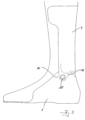
- Figure 1 shows an orthopedic technology device 2 in the form of an ankle orthosis. It has a first component 4 and a second component 6, wherein in the present exemplary embodiment the first component 4 is arranged on a user's lower leg, not shown, and the second component 6 is arranged on a user's foot, not shown.
- the first component 4 and the second component 6 are connected to one another by two connecting elements 8, each of which has a joint 10 with two joint parts 12 in the exemplary embodiment shown, which can be pivoted relative to one another.
- the joint parts 12 are each connected to a fastening rail 14 or are formed in one piece with such a fastening rail 14.
- the connecting elements 8 are individually tailored to the shape and orientation of the ankle and foot and/or the lower leg of the user of the orthopedic technology device 2.
- the fastening rails 14 are individually designed. You can see different fastening rails laterally and medially, which take into account the different geometries and different expected loads.
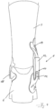
- Figure 2 shows the orthopedic technology facility 2 Figure 1 in a side view.
- the first component 4 and the second component 6 are connected to one another via the connecting element 8 with the joint 10 and the two joint parts 12.
- the fastening rail 14 is screwed on, the fastening rail 14 is arranged in one piece on the distal joint part 12.
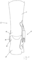
- Figure 3 shows another orthopedic technology device 2 in a side view.
- the first component 4 and the second component 6 each have a section 16, which are directly connected to one another, and an idler joint 18
- Figure 4 shows the orthopedic technology facility 2 Figure 3 in the rear view.
- the first component 4 and the second component 2 are, as already in Figure 3 shown, directly connected to one another by the idler joint 18 on one side, in the present case medially, while on the opposite side, in the present case lateral, a connecting element 8 is arranged.
- Figure 5 shows an orthopedic technology facility 2, which is in Figure 4 corresponds to the facility shown. They differ in a different design of the sections 16 on which the two components 4, 6 are directly connected to one another and form the idler joint 18.
- Figure 6a shows schematically a foot 20, which is measured and scanned with a scanner 22 becomes. This involves 3-dimensional data being recorded by the foot 20. A marking 24 is applied to the foot 20, which represents the position of a pivot axis, in this case an ankle axis. The marking 24 is chosen so that it can be detected by the scanner 22 and is therefore part of the 3-dimensional data. This data is then used to produce one of the two components to be connected later. Thanks to the scanned marking, this can be applied directly to the component. Later, the component or at least part of it is scanned in order to obtain the scan data (28), which preferably contains the position and/or orientation of the marking and thus of the component.
- the scan data 28
- a monitor 26 is shown. This illustrates that this and the method steps of the following two figures are carried out using an electronic data processing device, in particular a computer.
- the 3-dimensional scan data 28 are shown, which in the exemplary embodiment shown show a foot 20, on which the component scanned in the method according to the invention is located, in exactly the position in which the component is passed through the scanner 22 was recorded.
- a target position of the foot 20 is created, in which the foot is to be held by the orthopedic device 2 to be produced, which in the exemplary embodiment shown can be a foot lift orthosis. You can see that the forefoot area is raised.
- a connecting element is schematically adapted to the target data modulated in this way.
- a target position and/or a target orientation of the connecting element 8 relative to the 20 is determined. This is shown by the dashed box 30 and the axes 32 shown therein. This step is essentially about determining the position and orientation. Individual designs of the individual elements or components of the connecting element 8 are not yet determined in this step.
- the connecting element 8 is modeled on the target data of the foot 20. In the exemplary embodiment shown, it has three downwardly projecting arms 34, which form fastening sections and to which the connecting element 8 is later connected to the second component 6, in this case a foot part.
- the connecting element 8 also has a fastening device 36, which also forms a fastening section and with which it can be fastened to a first component 4, in the present case to a lower leg splint, in the exemplary embodiment shown.
- Figure 6e is shown schematically how the connecting element 8 is produced according to the data modulated in this way.
- a 3D printer 38 with at least one print head 40 is used in the exemplary embodiment shown.
Landscapes
- Health & Medical Sciences (AREA)
- Engineering & Computer Science (AREA)
- Animal Behavior & Ethology (AREA)
- Veterinary Medicine (AREA)
- Biomedical Technology (AREA)
- Heart & Thoracic Surgery (AREA)
- Vascular Medicine (AREA)
- Life Sciences & Earth Sciences (AREA)
- Public Health (AREA)
- General Health & Medical Sciences (AREA)
- Nursing (AREA)
- Orthopedic Medicine & Surgery (AREA)
- Robotics (AREA)
- Mechanical Engineering (AREA)
- Manufacturing & Machinery (AREA)
- Cardiology (AREA)
- Oral & Maxillofacial Surgery (AREA)
- Transplantation (AREA)
- Orthopedics, Nursing, And Contraception (AREA)
Claims (10)
- Procédé de fabrication d'un élément de liaison (8) pour relier deux composants (4, 6) d'un dispositif orthopédique (2) pour une partie du corps, le procédé comprenant les étapes suivantes consistant à :• acquérir des données de balayage tridimensionnelles (28) d'au moins une partie de chacun des deux composants (4, 6) au moyen d'un scanner (22),• déterminer une position de consigne et/ou une orientation de consigne de l'élément de liaison (8) par rapport aux composants (4, 6) à partir des données de balayage (28),• modéliser l'élément de liaison (8) au moyen des données de balayage (28), de la position de consigne et/ou de l'orientation de consigne et d'autres informations sur les composants (4, 6) à relier, et• fabriquer l'élément de liaison (8) modélisé.
- Procédé selon la revendication 1,
caractérisé en ce que, avant l'acquisition des données de balayage (28), au moins un marquage (24) reconnaissable par le scanner (22) est appliqué sur au moins l'un des deux composants (4, 6), de préférence sur les deux composants (4, 6). - Procédé selon la revendication 1 ou 2,
caractérisé en ce que l'un au moins des composants (4, 6) à relier et/ou l'élément de liaison (8) comprend une articulation (10). - Procédé selon l'une des revendications précédentes,
caractérisé en ce que les données de balayage (28) sont acquises dans au moins deux positions différentes des deux composants (4, 6). - Procédé selon l'une des revendications précédentes,
caractérisé en ce que, lors de la modélisation de l'élément de liaison (8), on effectue une simulation de la charge attendue, dont le résultat est pris en compte dans la modélisation de l'élément de liaison (8). - Procédé selon l'une des revendications précédentes,
caractérisé en ce que l'élément de liaison (8) modélisé est fabriqué au moyen d'un procédé de fabrication additive, en particulier un procédé d'impression 3D. - Procédé de fabrication d'un dispositif orthopédique (2) comprenant au moins deux composants (4, 6) qui sont reliés au moins également par un élément de liaison (8), le procédé comprenant les étapes suivantes consistant à :• fabriquer l'élément de liaison (8) selon l'une des revendications précédentes, et• relier les deux composants (4, 6) au moyen de l'élément de liaison (8) fabriqué.
- Procédé selon la revendication 7,
caractérisé en ce que les deux composants (4, 6) comprennent chacun au moins une portion (16), lesdites portions étant agencées directement l'une sur l'autre, de préférence de manière articulée, de manière particulièrement préférée au moyen d'une articulation suiveuse (18). - Procédé selon la revendication 7 ou 8,
caractérisé en ce qu'une portion de fixation (34, 36) de l'un au moins des deux composants (4, 6) est modélisée, après la modélisation de l'élément de liaison (8) ou lors de la modélisation de l'élément de liaison (8), au moyen des données de balayage (28), de la position de consigne et/ou de l'orientation de consigne et des autres informations sur les composants (4, 6) à relier. - Procédé selon l'une des revendications 7 à 9,
caractérisé en ce que l'un au moins des deux composants (4, 6) est un composant composite à fibres, et l'élément de liaison (8) est intégré dans une structure en couches du composant (4, 6) lors de la liaison avec ledit au moins un composant (4, 6).
Priority Applications (1)
| Application Number | Priority Date | Filing Date | Title |
|---|---|---|---|
| EP21181400.9A EP4108212B1 (fr) | 2021-06-24 | 2021-06-24 | Procédé de fabrication d'un élément de liaison |
Applications Claiming Priority (1)
| Application Number | Priority Date | Filing Date | Title |
|---|---|---|---|
| EP21181400.9A EP4108212B1 (fr) | 2021-06-24 | 2021-06-24 | Procédé de fabrication d'un élément de liaison |
Publications (2)
| Publication Number | Publication Date |
|---|---|
| EP4108212A1 EP4108212A1 (fr) | 2022-12-28 |
| EP4108212B1 true EP4108212B1 (fr) | 2024-01-31 |
Family
ID=76601054
Family Applications (1)
| Application Number | Title | Priority Date | Filing Date |
|---|---|---|---|
| EP21181400.9A Active EP4108212B1 (fr) | 2021-06-24 | 2021-06-24 | Procédé de fabrication d'un élément de liaison |
Country Status (1)
| Country | Link |
|---|---|
| EP (1) | EP4108212B1 (fr) |
Family Cites Families (4)
| Publication number | Priority date | Publication date | Assignee | Title |
|---|---|---|---|---|
| US7691076B2 (en) * | 2003-10-29 | 2010-04-06 | Castro Ernesto G | Articulated custom ankle-foot orthosis systems |
| GB0911953D0 (en) * | 2009-07-09 | 2009-08-19 | Materialise Nv | An artificial exoskeleton device, an orthotic or a prosthetic device comprising an integrated hinge structure |
| CN105310811A (zh) * | 2015-11-04 | 2016-02-10 | 上海交通大学 | 载荷平衡式膝关节矫形支具及其实现方法 |
| US20220339017A1 (en) * | 2019-09-19 | 2022-10-27 | The Regents Of The University Of Michigan | System and method for additively manufacturing an ankle foot orthosis |
-
2021
- 2021-06-24 EP EP21181400.9A patent/EP4108212B1/fr active Active
Also Published As
| Publication number | Publication date |
|---|---|
| EP4108212A1 (fr) | 2022-12-28 |
Similar Documents
| Publication | Publication Date | Title |
|---|---|---|
| EP3324897B1 (fr) | Procédure de fabrication d'une emboîture de prothèse et emboîture de prothèse | |
| WO2011026601A1 (fr) | Dispositif et procédé pour représenter une figure géométrique sur la surface d'un corps de patient | |
| EP2934397B1 (fr) | Structure de guidage et de support à appliquer sur un être vivant et procédé permettant de déterminer des surfaces d'appui appropriées sur l'être vivant | |
| AT507888B1 (de) | Verfahren zum herstellen einer stützeinrichtung für einen körperteil | |
| DE102018128514B4 (de) | Verfahren und Vorrichtung zum Durchführen eines Prothesenaufbaus | |
| EP3045152B1 (fr) | Procédé de fabrication d'une orthèse | |
| EP3711718B1 (fr) | Procédé de fabrication d'une orthèse de la main | |
| EP1843291A1 (fr) | Procédé et système d'élaboration d'une emboîture de prothèse | |
| EP4108212B1 (fr) | Procédé de fabrication d'un élément de liaison | |
| DE102015108848A1 (de) | Verfahren zum Herstellen einer kieferorthopädischen Korrekturvorrichtung | |
| DE102020108877A1 (de) | Verfahren zum Herstellen eines Verbindungselementes | |
| DE10138416B4 (de) | Verfahren zur Herstellung von Atemmasken, Epithesen oder Strahlenapplikatoren | |
| EP4061293B1 (fr) | Procédé pour réaliser une numérisation 3d | |
| EP3853678B1 (fr) | Procédé de positionnement d'une pièce à usiner et dispositif correspondant | |
| WO2016151020A1 (fr) | Procédé de production d'une orthèse | |
| DE102019122374A1 (de) | Verfahren zum Herstellen eines Prothesenschaftes | |
| DE102022117757A1 (de) | Verfahren und Computerprogramm zum Erstellen eines digitalen 3D-Modells sowie Verfahren zum Einstellen oder Herstellen einer orthopädietechnischen Versorgung | |
| EP0418420B1 (fr) | Procédé pour la fabrication d'une prothèse pour amputé fémoral | |
| DE102007014747A1 (de) | Verfahren und Vorrichtung zur Herstellung einer Struktur zur Verwendung als Orthese | |
| DE102021116536A1 (de) | Verfahren zum Vermessen und zum Herstellen eines Prothesenschaftes | |
| DE102021115467A1 (de) | Verfahren, Vorrichtung und Computerprogramm zum Erstellen von Fertigungsdaten für ein orthopädietechnisches Produkt | |
| WO2023001332A1 (fr) | Procédé et dispositif mis en œuvre par ordinateur permettant la définition géométrique d'un composant adapté à une unité d'organisme | |
| DE102022111332A1 (de) | Verfahren zum Einrichten einer orthopädietechnischen Vorrichtung | |
| DE102021130707A1 (de) | Verfahren zum Herstellen von Produktionsdaten und zum Herstellen eines Prothesenliners | |
| DE102018104386A1 (de) | Verfahren zum Erstellen eines Modells eines Hilfsmittels von einem bestehenden Hilfsmittel oder Negativabdruck, Vorrichtungen zur Digitalisierung eines Hilfsmittels, und Einheit zur Durchführung des Verfahrens |
Legal Events
| Date | Code | Title | Description |
|---|---|---|---|
| PUAI | Public reference made under article 153(3) epc to a published international application that has entered the european phase |
Free format text: ORIGINAL CODE: 0009012 |
|
| STAA | Information on the status of an ep patent application or granted ep patent |
Free format text: STATUS: THE APPLICATION HAS BEEN PUBLISHED |
|
| AK | Designated contracting states |
Kind code of ref document: A1 Designated state(s): AL AT BE BG CH CY CZ DE DK EE ES FI FR GB GR HR HU IE IS IT LI LT LU LV MC MK MT NL NO PL PT RO RS SE SI SK SM TR |
|
| STAA | Information on the status of an ep patent application or granted ep patent |
Free format text: STATUS: REQUEST FOR EXAMINATION WAS MADE |
|
| 17P | Request for examination filed |
Effective date: 20230420 |
|
| RBV | Designated contracting states (corrected) |
Designated state(s): AL AT BE BG CH CY CZ DE DK EE ES FI FR GB GR HR HU IE IS IT LI LT LU LV MC MK MT NL NO PL PT RO RS SE SI SK SM TR |
|
| GRAP | Despatch of communication of intention to grant a patent |
Free format text: ORIGINAL CODE: EPIDOSNIGR1 |
|
| STAA | Information on the status of an ep patent application or granted ep patent |
Free format text: STATUS: GRANT OF PATENT IS INTENDED |
|
| RIC1 | Information provided on ipc code assigned before grant |
Ipc: B25J 9/00 20060101ALI20230822BHEP Ipc: A61F 5/01 20060101ALI20230822BHEP Ipc: A61F 2/50 20060101AFI20230822BHEP |
|
| INTG | Intention to grant announced |
Effective date: 20230915 |
|
| GRAS | Grant fee paid |
Free format text: ORIGINAL CODE: EPIDOSNIGR3 |
|
| GRAA | (expected) grant |
Free format text: ORIGINAL CODE: 0009210 |
|
| STAA | Information on the status of an ep patent application or granted ep patent |
Free format text: STATUS: THE PATENT HAS BEEN GRANTED |
|
| AK | Designated contracting states |
Kind code of ref document: B1 Designated state(s): AL AT BE BG CH CY CZ DE DK EE ES FI FR GB GR HR HU IE IS IT LI LT LU LV MC MK MT NL NO PL PT RO RS SE SI SK SM TR |
|
| REG | Reference to a national code |
Ref country code: GB Ref legal event code: FG4D Free format text: NOT ENGLISH Ref country code: CH Ref legal event code: EP |
|
| REG | Reference to a national code |
Ref country code: DE Ref legal event code: R096 Ref document number: 502021002546 Country of ref document: DE |
|
| REG | Reference to a national code |
Ref country code: IE Ref legal event code: FG4D Free format text: LANGUAGE OF EP DOCUMENT: GERMAN |