EP4108212B1 - Method for producing a connection element - Google Patents
Method for producing a connection element Download PDFInfo
- Publication number
- EP4108212B1 EP4108212B1 EP21181400.9A EP21181400A EP4108212B1 EP 4108212 B1 EP4108212 B1 EP 4108212B1 EP 21181400 A EP21181400 A EP 21181400A EP 4108212 B1 EP4108212 B1 EP 4108212B1
- Authority
- EP
- European Patent Office
- Prior art keywords
- connecting element
- components
- scan data
- body part
- component
- Prior art date
- Legal status (The legal status is an assumption and is not a legal conclusion. Google has not performed a legal analysis and makes no representation as to the accuracy of the status listed.)
- Active
Links
- 238000004519 manufacturing process Methods 0.000 title claims description 18
- 230000000399 orthopedic effect Effects 0.000 claims description 43
- 238000000034 method Methods 0.000 claims description 32
- 239000000835 fiber Substances 0.000 claims description 17
- 239000002131 composite material Substances 0.000 claims description 12
- 239000000654 additive Substances 0.000 claims description 5
- 230000000996 additive effect Effects 0.000 claims description 5
- 238000004088 simulation Methods 0.000 claims description 3
- 238000010146 3D printing Methods 0.000 claims description 2
- 230000003466 anti-cipated effect Effects 0.000 claims 1
- 210000002683 foot Anatomy 0.000 description 14
- 239000000463 material Substances 0.000 description 12
- 238000005516 engineering process Methods 0.000 description 11
- 210000003423 ankle Anatomy 0.000 description 9
- 210000003127 knee Anatomy 0.000 description 9
- 230000005855 radiation Effects 0.000 description 5
- 210000000689 upper leg Anatomy 0.000 description 5
- 210000002414 leg Anatomy 0.000 description 4
- 239000002184 metal Substances 0.000 description 4
- 229920000049 Carbon (fiber) Polymers 0.000 description 3
- 239000004917 carbon fiber Substances 0.000 description 3
- 238000007639 printing Methods 0.000 description 3
- 210000000988 bone and bone Anatomy 0.000 description 2
- VNWKTOKETHGBQD-UHFFFAOYSA-N methane Chemical compound C VNWKTOKETHGBQD-UHFFFAOYSA-N 0.000 description 2
- 239000011505 plaster Substances 0.000 description 2
- 229920003002 synthetic resin Polymers 0.000 description 2
- 239000000057 synthetic resin Substances 0.000 description 2
- 210000001519 tissue Anatomy 0.000 description 2
- 238000004040 coloring Methods 0.000 description 1
- 239000004744 fabric Substances 0.000 description 1
- 239000011152 fibreglass Substances 0.000 description 1
- 239000002657 fibrous material Substances 0.000 description 1
- 239000006260 foam Substances 0.000 description 1
- 210000004744 fore-foot Anatomy 0.000 description 1
- 239000003365 glass fiber Substances 0.000 description 1
- 210000003141 lower extremity Anatomy 0.000 description 1
- 239000004033 plastic Substances 0.000 description 1
- 229920000642 polymer Polymers 0.000 description 1
- 231100000241 scar Toxicity 0.000 description 1
- 238000007493 shaping process Methods 0.000 description 1
- 210000004872 soft tissue Anatomy 0.000 description 1
- 230000000087 stabilizing effect Effects 0.000 description 1
- 229920002994 synthetic fiber Polymers 0.000 description 1
- 239000012209 synthetic fiber Substances 0.000 description 1
- 239000004753 textile Substances 0.000 description 1
- 229920001169 thermoplastic Polymers 0.000 description 1
- 229920001187 thermosetting polymer Polymers 0.000 description 1
- 239000004416 thermosoftening plastic Substances 0.000 description 1
Images


Classifications
-
- A—HUMAN NECESSITIES
- A61—MEDICAL OR VETERINARY SCIENCE; HYGIENE
- A61F—FILTERS IMPLANTABLE INTO BLOOD VESSELS; PROSTHESES; DEVICES PROVIDING PATENCY TO, OR PREVENTING COLLAPSING OF, TUBULAR STRUCTURES OF THE BODY, e.g. STENTS; ORTHOPAEDIC, NURSING OR CONTRACEPTIVE DEVICES; FOMENTATION; TREATMENT OR PROTECTION OF EYES OR EARS; BANDAGES, DRESSINGS OR ABSORBENT PADS; FIRST-AID KITS
- A61F2/00—Filters implantable into blood vessels; Prostheses, i.e. artificial substitutes or replacements for parts of the body; Appliances for connecting them with the body; Devices providing patency to, or preventing collapsing of, tubular structures of the body, e.g. stents
- A61F2/50—Prostheses not implantable in the body
- A61F2/5044—Designing or manufacturing processes
-
- A—HUMAN NECESSITIES
- A61—MEDICAL OR VETERINARY SCIENCE; HYGIENE
- A61F—FILTERS IMPLANTABLE INTO BLOOD VESSELS; PROSTHESES; DEVICES PROVIDING PATENCY TO, OR PREVENTING COLLAPSING OF, TUBULAR STRUCTURES OF THE BODY, e.g. STENTS; ORTHOPAEDIC, NURSING OR CONTRACEPTIVE DEVICES; FOMENTATION; TREATMENT OR PROTECTION OF EYES OR EARS; BANDAGES, DRESSINGS OR ABSORBENT PADS; FIRST-AID KITS
- A61F5/00—Orthopaedic methods or devices for non-surgical treatment of bones or joints; Nursing devices; Anti-rape devices
- A61F5/01—Orthopaedic devices, e.g. splints, casts or braces
-
- B—PERFORMING OPERATIONS; TRANSPORTING
- B25—HAND TOOLS; PORTABLE POWER-DRIVEN TOOLS; MANIPULATORS
- B25J—MANIPULATORS; CHAMBERS PROVIDED WITH MANIPULATION DEVICES
- B25J9/00—Programme-controlled manipulators
- B25J9/0006—Exoskeletons, i.e. resembling a human figure
-
- A—HUMAN NECESSITIES
- A61—MEDICAL OR VETERINARY SCIENCE; HYGIENE
- A61F—FILTERS IMPLANTABLE INTO BLOOD VESSELS; PROSTHESES; DEVICES PROVIDING PATENCY TO, OR PREVENTING COLLAPSING OF, TUBULAR STRUCTURES OF THE BODY, e.g. STENTS; ORTHOPAEDIC, NURSING OR CONTRACEPTIVE DEVICES; FOMENTATION; TREATMENT OR PROTECTION OF EYES OR EARS; BANDAGES, DRESSINGS OR ABSORBENT PADS; FIRST-AID KITS
- A61F2/00—Filters implantable into blood vessels; Prostheses, i.e. artificial substitutes or replacements for parts of the body; Appliances for connecting them with the body; Devices providing patency to, or preventing collapsing of, tubular structures of the body, e.g. stents
- A61F2/50—Prostheses not implantable in the body
- A61F2/5044—Designing or manufacturing processes
- A61F2/5046—Designing or manufacturing processes for designing or making customized prostheses, e.g. using templates, finite-element analysis or CAD-CAM techniques
- A61F2002/5047—Designing or manufacturing processes for designing or making customized prostheses, e.g. using templates, finite-element analysis or CAD-CAM techniques using mathematical models
- A61F2002/5049—Computer aided shaping, e.g. rapid prototyping
-
- A—HUMAN NECESSITIES
- A61—MEDICAL OR VETERINARY SCIENCE; HYGIENE
- A61F—FILTERS IMPLANTABLE INTO BLOOD VESSELS; PROSTHESES; DEVICES PROVIDING PATENCY TO, OR PREVENTING COLLAPSING OF, TUBULAR STRUCTURES OF THE BODY, e.g. STENTS; ORTHOPAEDIC, NURSING OR CONTRACEPTIVE DEVICES; FOMENTATION; TREATMENT OR PROTECTION OF EYES OR EARS; BANDAGES, DRESSINGS OR ABSORBENT PADS; FIRST-AID KITS
- A61F2/00—Filters implantable into blood vessels; Prostheses, i.e. artificial substitutes or replacements for parts of the body; Appliances for connecting them with the body; Devices providing patency to, or preventing collapsing of, tubular structures of the body, e.g. stents
- A61F2/50—Prostheses not implantable in the body
- A61F2/5044—Designing or manufacturing processes
- A61F2/5046—Designing or manufacturing processes for designing or making customized prostheses, e.g. using templates, finite-element analysis or CAD-CAM techniques
- A61F2002/505—Designing or manufacturing processes for designing or making customized prostheses, e.g. using templates, finite-element analysis or CAD-CAM techniques using CAD-CAM techniques or NC-techniques
Definitions
- the invention relates to a method for producing a connecting element for connecting two components of an orthopedic device for a body part.
- the invention also relates to a method for producing the orthopedic device.
- CN105310811 A and US2011/009787 A1 disclose methods for producing connecting elements for orthopedic devices. Scan data from the leg of the orthosis wearer is used, and based on this, components and connecting elements are manufactured in parallel, adapted to the wearer. It is not intended to produce a connecting element for components that have already been manufactured.
- WO2021/055533 A1 and US2005/096576 A1 disclose methods for producing fasteners, but no scan data is used for customization.
- Orthopedic technical devices have long been known from the prior art and include, for example, orthoses that can protect, support or, for example, restrict movement of an existing part of the wearer's body, prostheses that replace a part of the wearer's body and exoskeletons for supporting parts of the body.
- An orthosis for a body part is usually placed on that part of the body.
- a knee orthosis is arranged on a knee of the wearer and an elbow orthosis on an elbow of the wearer.
- such an orthosis is designed for the respective body part.
- a prosthesis is placed on an existing part of the wearer's body.
- a knee orthosis can, for example, be arranged on a thigh stump using a prosthetic socket.
- such a knee prosthesis is an orthopedic device for the thigh.
- an orthopedic technical device is an orthopedic technical device for a body part if it is arranged on this body part or supports, protects, supports or spans this body part.
- a knee orthosis is usually placed on the thigh and lower leg, but spans and supports the knee. It can therefore be viewed and described as an orthopedic device for the knee as well as for the thigh and lower leg.
- An orthopedic device usually consists of more than two components that have to be connected to each other. Fasteners are used for this. These can rigidly connect two components together so that in the connected state no movement of the two components relative to each other is possible. This is for example This is the case with a shaft adapter, which is arranged on a prosthetic shaft and connects it to another prosthetic element, for example a prosthetic knee or a tubular element. The orientation of the two components relative to one another can be adjusted if necessary, but in the connected state a relative movement is undesirable and therefore excluded.
- a connecting element can also be designed in such a way that the two components can be moved relative to one another in the connected state. This is the case, for example, if the connecting element has a joint or is designed as a joint.
- a joint connects, for example, a thigh element and a lower leg element of a knee orthosis or a lower leg element and a foot element of an ankle orthosis.
- a joint leg of such a connecting element is designed as a metal component that forms a flat surface and has a length that enables a sufficient connection to one of the components to be connected.
- This joint leg is deformed when the orthopedic device is manufactured in order to bring it into the desired shape. This is usually done by the orthopedic technician who produces the orthopedic device.
- the metal joint leg is bent when cold. Although this achieves the desired shape, the material is subjected to heavy mechanical stress, so that its stability is reduced.
- the connecting element is usually initially manufactured with a greater material thickness than would actually be necessary for the loads that occur. This increases the amount of material and thus the cost and weight of the connecting element and also makes the forming process by the orthopedic technician more difficult.
- the invention is therefore based on the object of further developing a method for producing a connecting element and an orthopedic device in such a way that the disadvantages of the prior art are eliminated or at least mitigated.
- the method according to the invention produces a connecting element that preferably no longer needs to be reshaped by the orthopedic technician. This allows the material thickness to be reduced to the necessary minimum, thereby reducing the use of materials and thus the manufacturing costs. In addition, the manufacturing time for the orthopedic device is shortened because the orthopedic technician has to carry out fewer procedural steps.
- each of the two components to be connected is scanned using a scanner, whereby the 3-dimensional scan data is captured.
- These are in the form of electronic data that can be stored, for example, in a data memory of an electronic data processing device.
- the scanner is preferably a mobile device, which is, for example, a hand-held scanner.
- Such a hand scanner can preferably be operated with one hand and is aimed at the body part by the person carrying out the procedure in such a way that the scan data is recorded.
- the component to be scanned is preferably irradiated with suitable scanning radiation, which is then detected using a suitable detector.
- the scanning radiation is, for example, a light pattern visible light and/or infrared radiation and the detector is a camera designed for the wavelength of radiation used.
- the scan data is preferably recorded using a photogrammetric method. In other words, photogrammetry is performed to capture the scan data.
- At least one stationary scanner can also be used.
- the component to be scanned is preferably irradiated with suitable scanning radiation.
- a plurality of detectors for example suitable cameras, are arranged around the component, which detect and image the component from different spatial directions.
- the scan data is determined from the individual images captured in this way using image processing.
- the processes and procedures for capturing the scan data are very similar or even identical to the processes and procedures used with a mobile scanner.
- a stationary scanner it is possible to record a plurality of individual images with the plurality of detectors, in particular cameras, simultaneously or at short intervals, while when using a mobile scanner a longer time passes until the necessary data is obtained from the different viewing angles perspectives are captured. Since the body part should preferably not be moved while the scan data is being captured, using a stationary scanner is advantageous. However, this increases the expenditure on equipment.
- the target position and/or the target orientation of the connecting element relative to the components is determined.
- the connecting element is then modeled, taking into account the target position and/or target orientation determined in this way.
- the connecting element is modeled in a geometric configuration that makes further shaping at a later point in time unnecessary.
- the space available for the connecting element is taken into account, which results from the scan data, i.e. the underlying physical conditions, and the components to be connected.
- the two components have preferably been individually adapted to the respective patient. This can be done, for example, by first scanning or taking a mold of the body part to be treated, for example using plaster. Those preserved in this way Scan data or the impression are used to individually adapt the components.
- the component is preferably a component made from a thermoplastic by deep drawing. If the patient's body part has been molded using a plaster cast, it can be deep-drawn onto a positive model created from the cast. If a scan of the body part has been made, the deep drawing is carried out, for example, on a hard foam model milled according to the scan data.
- At least one of the two components, but preferably both components to be connected, is produced based on data obtained by scanning the respective body part.
- a mobile and/or stationary scanner can also be used for this.
- a so-called purpose form is first created from the data obtained in this way.
- the data is modified in such a way that an orthopedic technology device adapted to these modified scan data fulfills its purpose on the actual body part well and as optimally as possible.
- This is preferably done automatically by means of an electronic control, for example software running within an electronic data processing device, which is set up to modify the scan data and thus create the purpose form.
- the target position and/or the target orientation is determined based on the purpose form created.
- the volume of a body part is changed, preferably enlarged, or a position and/or orientation of a body part is adjusted to another body part.
- the position of the foot relative to the lower leg can be adjusted and changed from the actual position represented by the data obtained by scanning the body part.
- At least one marking that can be recognized by the scanner is applied to at least one of the two components, preferably to both components, before the scan data is recorded.
- the marking is preferably glued to the component or applied to the body part with a color that can be detected using the scanner. It is important that the marking is also included and recognizable in the scan data. In particular, but not exclusively, in the case that the component was manufactured using an additive manufacturing process, at least one marking is already in applied to the component using this manufacturing process.
- the marking can, for example, contain a coloring, an elevation and/or a depression that can be recognized by the respective scanner used.
- the at least one marking preferably marks locations of the component that are important for the positioning of the connecting element and/or one or both components that are to be connected by the connecting element. These points preferably mark the course and/or the position of joint axes of the body part, particularly sensitive places such as sensitive soft tissues, scar tissue or places where a bone or bone end is only covered by a thin layer of tissue. If several different locations on the component are each provided with a marking, different markings are preferably used. This preferably makes it possible to identify the individual marked locations from the type of marking in the scan data.
- one of the components to be connected and/or the connecting element has a joint.
- the target position and/or the target orientation is determined such that a joint axis of the joint coincides with a joint axis of the body part. This is particularly easy if the joint axis of the body part has been marked on the body part and this can be recognized in the scan data.
- the scan data is recorded in two different positions and/or loads on the components. These different positions preferably correspond to different positions of the respective body part for which the orthopedic device is being manufactured.
- the orthopedic technology device is intended to apply a force to the body part that leads to a deformation of the body part.
- the orthopedic technology device is preferably placed on the body part without any force being initially applied.
- scan data is preferably recorded in the unloaded state of the body part. Only after application will the orthopedic technology device apply the desired force and cause the deformation of the body part.
- the orthopedic device can be adjusted, for example by tensioning a belt or adjusting a joint.
- the deformation occurs due to a Loading of the body part with the orthopedic device located on it. This is particularly relevant for orthopedic devices in the form of prosthetic sockets, especially for the lower extremities.
- a simulation of the expected load is preferably carried out, the result of which is incorporated into the modeling of the connecting element. Movements of the body part on which the orthopedic device is arranged are preferably simulated and the forces that occur are determined. The connecting element is then modeled so that it can withstand the determined forces.
- a target position and/or target orientation relative to both components is also determined.
- a position and/or orientation of the connecting element can be varied, with the expected loads and forces preferably being determined for each new position.
- the connecting element is preferably produced using an additive manufacturing process, in particular a 3D printing process.
- a metal and/or a plastic, in particular a thermoset or polymer, is preferably used as the printing material.
- Fibers are particularly preferably incorporated into the printing material as stabilizing elements. These can be textile fibers, natural fibers, synthetic fibers, glass fibers, carbon fibers or metal fibers.
- a fiber is understood in particular to mean an almost one-dimensional element, which consequently has a significantly greater extent in a first direction, which is referred to as the longitudinal direction, than in the plane perpendicular to this longitudinal direction.
- the fibers are preferably introduced into the printing material in a controlled manner during the additive manufacturing process. This means that preferably during modeling of the connecting element, the amount and direction of the longitudinal extension of the fibers is predetermined.
- the length of the fibers to be introduced is also particularly preferably predetermined.
- the quantity, length, material and/or longitudinal direction of the fibers to be introduced are taken into account. This makes it possible to influence the stability of the connecting element in predetermined areas and in predetermined directions and thus further reduce the amount of material required.
- the connecting element forms a joint with one of the components to be connected, through which the two components can be moved, preferably pivoted, relative to one another in the connected state.
- the connecting element and one of the components each have a hole. These holes are brought into alignment with each other when assembling the orthopedic device.
- an axle element for example a screw, a pin, rod or bolt, is guided through the two holes and fastened therein, so that the connecting element can be pivoted about this axle element relative to the component.
- the connecting element is arranged rigidly, in particular in a rotationally fixed manner, on the other of the two components, the two components that are connected by the connecting element can be pivoted relative to one another.
- the connecting element preferably has at least one fastening rail, particularly preferably two fastening rails, which are arranged on the two joint parts of the joint, which are movable relative to one another.
- the at least one fastening rail is designed in one piece with the respective joint part.
- the two components each have at least one section, which are arranged directly on one another, preferably in an articulated manner, particularly preferably by means of an idler joint. In this way, for example, a follower joint is produced.
- the two sections are preferably arranged on the opposite side, for example medially.
- the sections are arranged in such a way that, when connected, they reduce torsional forces, relieve the load on the connecting element and/or improve the stability of the orthopedic device and/or its attachment to the body part.
- a fastening section of at least one of the two components is modeled after modeling the connecting element or when modeling the connecting element using the scan data, the target position and/or the target orientation and the further information about the respective component.
- one of the two components particularly preferred are both components, after modeling the connecting element or when modeling the connecting element using the scan data, the target position and/or the target orientation and the further information about the components to be connected modeled.
- At least one of the two components of the orthopedic device to be produced is a fiber composite component.
- Both components to be connected are particularly preferably fiber composite components. These can be carbon fiber composite components or fiberglass composite components or other composite components.
- the connecting element is connected when connecting to the at least one component designed as a composite component, but preferably to both components designed as composite components, and is thereby integrated into the layer structure of the respective component.
- Fiber composite components are made from so-called prepregs, which are usually fabric elements, for example fiber mats made from the respective fiber material. These are placed in the desired shape and are usually coated with a synthetic resin, which produces the fiber composite material when it hardens. The individual fiber mats are often already soaked or coated with the synthetic resin.
- the connecting element is also arranged in the mold, in particular between different layers of the fiber mats of the composite material.
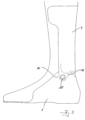
- Figure 1 shows an orthopedic technology device 2 in the form of an ankle orthosis. It has a first component 4 and a second component 6, wherein in the present exemplary embodiment the first component 4 is arranged on a user's lower leg, not shown, and the second component 6 is arranged on a user's foot, not shown.
- the first component 4 and the second component 6 are connected to one another by two connecting elements 8, each of which has a joint 10 with two joint parts 12 in the exemplary embodiment shown, which can be pivoted relative to one another.
- the joint parts 12 are each connected to a fastening rail 14 or are formed in one piece with such a fastening rail 14.
- the connecting elements 8 are individually tailored to the shape and orientation of the ankle and foot and/or the lower leg of the user of the orthopedic technology device 2.
- the fastening rails 14 are individually designed. You can see different fastening rails laterally and medially, which take into account the different geometries and different expected loads.
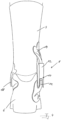
- Figure 2 shows the orthopedic technology facility 2 Figure 1 in a side view.
- the first component 4 and the second component 6 are connected to one another via the connecting element 8 with the joint 10 and the two joint parts 12.
- the fastening rail 14 is screwed on, the fastening rail 14 is arranged in one piece on the distal joint part 12.
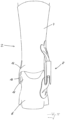
- Figure 3 shows another orthopedic technology device 2 in a side view.
- the first component 4 and the second component 6 each have a section 16, which are directly connected to one another, and an idler joint 18
- Figure 4 shows the orthopedic technology facility 2 Figure 3 in the rear view.
- the first component 4 and the second component 2 are, as already in Figure 3 shown, directly connected to one another by the idler joint 18 on one side, in the present case medially, while on the opposite side, in the present case lateral, a connecting element 8 is arranged.
- Figure 5 shows an orthopedic technology facility 2, which is in Figure 4 corresponds to the facility shown. They differ in a different design of the sections 16 on which the two components 4, 6 are directly connected to one another and form the idler joint 18.
- Figure 6a shows schematically a foot 20, which is measured and scanned with a scanner 22 becomes. This involves 3-dimensional data being recorded by the foot 20. A marking 24 is applied to the foot 20, which represents the position of a pivot axis, in this case an ankle axis. The marking 24 is chosen so that it can be detected by the scanner 22 and is therefore part of the 3-dimensional data. This data is then used to produce one of the two components to be connected later. Thanks to the scanned marking, this can be applied directly to the component. Later, the component or at least part of it is scanned in order to obtain the scan data (28), which preferably contains the position and/or orientation of the marking and thus of the component.
- the scan data 28
- a monitor 26 is shown. This illustrates that this and the method steps of the following two figures are carried out using an electronic data processing device, in particular a computer.
- the 3-dimensional scan data 28 are shown, which in the exemplary embodiment shown show a foot 20, on which the component scanned in the method according to the invention is located, in exactly the position in which the component is passed through the scanner 22 was recorded.
- a target position of the foot 20 is created, in which the foot is to be held by the orthopedic device 2 to be produced, which in the exemplary embodiment shown can be a foot lift orthosis. You can see that the forefoot area is raised.
- a connecting element is schematically adapted to the target data modulated in this way.
- a target position and/or a target orientation of the connecting element 8 relative to the 20 is determined. This is shown by the dashed box 30 and the axes 32 shown therein. This step is essentially about determining the position and orientation. Individual designs of the individual elements or components of the connecting element 8 are not yet determined in this step.
- the connecting element 8 is modeled on the target data of the foot 20. In the exemplary embodiment shown, it has three downwardly projecting arms 34, which form fastening sections and to which the connecting element 8 is later connected to the second component 6, in this case a foot part.
- the connecting element 8 also has a fastening device 36, which also forms a fastening section and with which it can be fastened to a first component 4, in the present case to a lower leg splint, in the exemplary embodiment shown.
- Figure 6e is shown schematically how the connecting element 8 is produced according to the data modulated in this way.
- a 3D printer 38 with at least one print head 40 is used in the exemplary embodiment shown.
Description
Die Erfindung betrifft ein Verfahren zum Herstellen eines Verbindungselementes zum Verbinden zweier Bauteile einer orthopädietechnischen Einrichtung für ein Körperteil. Die Erfindung betrifft zudem ein Verfahren zum Herstellen der orthopädietechnischen Einrichtung.The invention relates to a method for producing a connecting element for connecting two components of an orthopedic device for a body part. The invention also relates to a method for producing the orthopedic device.
Orthopädietechnische Einrichtungen sind aus dem Stand der Technik seit langem bekannt und umfassen beispielsweise Orthesen, die ein vorhandenes Körperteil des Trägers schützen, stützen oder beispielsweise in der Bewegung einschränken können, Prothesen, die ein Körperteil des Trägers ersetzen und Exoskelette zur Unterstützung von Körperteilen.Orthopedic technical devices have long been known from the prior art and include, for example, orthoses that can protect, support or, for example, restrict movement of an existing part of the wearer's body, prostheses that replace a part of the wearer's body and exoskeletons for supporting parts of the body.
Eine Orthese für ein Körperteil wird in der Regel an diesem Körperteil angeordnet. Eine Knieorthese wird beispielsweise an einem Knie des Trägers und eine Ellenbogenorthese an einem Ellenbogen des Trägers angeordnet. Im Sinne der vorliegenden Anmeldung ist eine solche Orthese für das jeweilige Körperteil ausgebildet. Eine Prothese hingegen wird an einem vorhandenen Körperteil des Trägers angeordnet. Eine Knieorthese kann beispielsweise mittels eines Prothesenschaftes an einem Oberschenkelstumpf angeordnet werden. Im Sinne der vorliegenden Erfindung ist eine solche Knieprothese eine orthopädietechnische Einrichtung für den Oberschenkel. Eine orthopädietechnische Einrichtung ist im Sinne der vorliegenden Erfindung eine orthopädietechnische Einrichtung für ein Körperteil, wenn sie an diesem Körperteil angeordnet wird oder dieses Körperteil unterstützt, schützt, stützt oder überspannt. Eine Knieorthese wird in der Regel zwar am Oberschenkel und dem Unterschenkel angeordnet, überspannt und stützt jedoch das Knie. Sie kann also sowohl als eine orthopädietechnische Einrichtung für das Knie als auch für den Oberschenkel und den Unterschenkel angesehen und bezeichnet werden.An orthosis for a body part is usually placed on that part of the body. For example, a knee orthosis is arranged on a knee of the wearer and an elbow orthosis on an elbow of the wearer. In the sense of the present application, such an orthosis is designed for the respective body part. A prosthesis, on the other hand, is placed on an existing part of the wearer's body. A knee orthosis can, for example, be arranged on a thigh stump using a prosthetic socket. For the purposes of the present invention, such a knee prosthesis is an orthopedic device for the thigh. For the purposes of the present invention, an orthopedic technical device is an orthopedic technical device for a body part if it is arranged on this body part or supports, protects, supports or spans this body part. A knee orthosis is usually placed on the thigh and lower leg, but spans and supports the knee. It can therefore be viewed and described as an orthopedic device for the knee as well as for the thigh and lower leg.
Eine orthopädietechnische Einrichtung besteht in der Regel aus mehr als zwei Bauteilen, die miteinander verbunden werden müssen. Dazu werden Verbindungselemente verwendet. Diese können zwei Bauteile starr miteinander verbinden, so dass im verbundenen Zustand keine Bewegung der beiden Bauteile relativ zueinander möglich ist. Dies ist beispielsweise bei einem Schaftadapter der Fall, der an einem Prothesenschaft angeordnet wird und diesen mit einem weiteren Prothesenelement, beispielsweise einem Prothesenknie oder einem Rohrelement verbindet. Die Orientierung der beiden Bauteile relativ zueinander ist gegebenenfalls einstellbar, im verbundenen Zustand ist eine Relativbewegung jedoch unerwünscht und deswegen ausgeschlossen.An orthopedic device usually consists of more than two components that have to be connected to each other. Fasteners are used for this. These can rigidly connect two components together so that in the connected state no movement of the two components relative to each other is possible. This is for example This is the case with a shaft adapter, which is arranged on a prosthetic shaft and connects it to another prosthetic element, for example a prosthetic knee or a tubular element. The orientation of the two components relative to one another can be adjusted if necessary, but in the connected state a relative movement is undesirable and therefore excluded.
Ein Verbindungselement kann aber auch derart ausgebildet sein, dass die beiden Bauteile im verbundenen Zustand relativ zueinander bewegbar sind. Dies ist beispielsweise der Fall, wenn das Verbindungselement ein Gelenk aufweist oder als Gelenk ausgebildet ist. Ein solches Gelenk verbindet beispielsweise ein Oberschenkelelement und ein Unterschenkelelement einer Knieorthese oder ein Unterschenkelelement und ein Fußelement einer Knöchelorthese.However, a connecting element can also be designed in such a way that the two components can be moved relative to one another in the connected state. This is the case, for example, if the connecting element has a joint or is designed as a joint. Such a joint connects, for example, a thigh element and a lower leg element of a knee orthosis or a lower leg element and a foot element of an ankle orthosis.
Insbesondere für den Fall, dass das Verbindungselement Bauteile miteinander verbindet, von denen wenigstens eines, bevorzugt jedoch beide, individuell für den Träger der orthopädietechnischen Einrichtung angefertigt wurden, etwa als Kohlefaserverbund-Bauteil, wird oft auch das Verbindungselement an die individuellen Bedürfnisse und Gegebenheiten angepasst. So ist beispielsweise ein Gelenkschenkel eines derartigen Verbindungselementes als Metallbauteil ausgebildet, das eine eben Fläche bildet und eine Länge aufweist, die eine ausreichende Verbindung mit einem der zu verbindenden Bauteile ermöglicht. Dieser Gelenkschenkel wird beim Herstellen der orthopädietechnischen Einrichtung verformt um ihn in die gewünschte Form zu bringen. Dies geschieht in der Regel durch den Orthopädietechniker, der die orthopädietechnische Einrichtung herstellt. Dabei wird im einfachsten Fall der aus Metall bestehende Gelenkschenkel im kalten Zustand gebogen. Dadurch wird zwar die gewünschte Form erreicht, das Material jedoch mechanisch stark belastet, so dass seine Stabilität reduziert wird.In particular, in the event that the connecting element connects components to one another, of which at least one, but preferably both, were manufactured individually for the wearer of the orthopedic device, for example as a carbon fiber composite component, the connecting element is often adapted to the individual needs and circumstances. For example, a joint leg of such a connecting element is designed as a metal component that forms a flat surface and has a length that enables a sufficient connection to one of the components to be connected. This joint leg is deformed when the orthopedic device is manufactured in order to bring it into the desired shape. This is usually done by the orthopedic technician who produces the orthopedic device. In the simplest case, the metal joint leg is bent when cold. Although this achieves the desired shape, the material is subjected to heavy mechanical stress, so that its stability is reduced.
Um dies auszugleichen wird das Verbindungselement zunächst meist mit einer größeren Materialstärke hergestellt, als dies für die auftretenden Belastungen eigentlich notwendig wäre. Dadurch wird der Materialaufwand und damit die Kosten und das Gewicht des Verbindungselementes erhöht und zudem die umformende Bearbeitung durch den Orthopädietechniker erschwert.To compensate for this, the connecting element is usually initially manufactured with a greater material thickness than would actually be necessary for the loads that occur. This increases the amount of material and thus the cost and weight of the connecting element and also makes the forming process by the orthopedic technician more difficult.
Der Erfindung liegt daher die Aufgabe zugrunde, ein Verfahren zum Herstellen eines Verbindungselementes und einer orthopädietechnischen Einrichtung so weiterzuentwickeln, dass die Nachteile aus dem Stand der Technik behoben oder zumindest abgemildert werden.The invention is therefore based on the object of further developing a method for producing a connecting element and an orthopedic device in such a way that the disadvantages of the prior art are eliminated or at least mitigated.
Die Erfindung löst die gestellte Aufgabe durch ein Verfahren zum Herstellen eines Verbindungselementes zum Verbinden zweier Bauteile einer orthopädietechnischen Einrichtung für ein Körperteil, das die folgenden Schritte aufweist:
- Erfassen von 3-dimensionalen Scan-Daten zumindest eines Teils jedes der beiden Bauteile mittels eines Scanners,
- Bestimmen einer Soll-Position und/oder eine Soll-Orientierung des Verbindungselementes relativ zu den Bauteilen aus den Scan-Daten,
- Modellieren des Verbindungselementes mittels der Scan-Daten, der Soll-Position und/oder der Soll-Orientierung und weiteren Informationen über die zu verbindenden Bauteile
und - Fertigen des modellierten Verbindungselementes.
- Acquiring 3-dimensional scan data of at least part of each of the two components using a scanner,
- Determining a target position and/or a target orientation of the connecting element relative to the components from the scan data,
- Modeling the connecting element using the scan data, the target position and/or the target orientation and further information about the components to be connected
and - Manufacture of the modeled connecting element.
Durch das erfindungsgemäße Verfahren wird ein Verbindungselement hergestellt, das vorzugsweise nicht mehr durch den Orthopädietechniker umgeformt werden muss. Dadurch kann die Materialstärke auf das notwendige Mindestmaß reduziert werden, wodurch der Materialeinsatz und damit die Herstellungskosten gesenkt werden. Zudem verkürzt sich die Herstellungszeit für die orthopädietechnische Einrichtung, da der Orthopädietechniker weniger Verfahrensschritte durchführen muss.The method according to the invention produces a connecting element that preferably no longer needs to be reshaped by the orthopedic technician. This allows the material thickness to be reduced to the necessary minimum, thereby reducing the use of materials and thus the manufacturing costs. In addition, the manufacturing time for the orthopedic device is shortened because the orthopedic technician has to carry out fewer procedural steps.
Zunächst wird zumindest ein Teil jedes der beiden zu verbindenden Bauteile, vorzugsweise jedoch die gesamten Bauteile, mittels eines Scanners gescannt, wodurch die 3-dimensionalen Scan-Daten erfasst werden. Diese liegen in Form von elektronischen Daten vor, die beispielsweise in einem Datenspeicher einer elektronischen Datenverarbeitungseinrichtung hinterlegt werden können. Der Scanner ist vorzugsweise ein mobiles Gerät, das beispielsweise ein Handscanner ist. Ein solcher Handscanner ist vorzugsweise mit einer Hand bedienbar und wird von einer das Verfahren durchführenden Person so auf das Körperteil gerichtet, dass die Scan-Daten erfasst werden. Dabei wird das jeweils zu scannende Bauteil vorzugweise mit einer geeigneten Scan-Strahlung bestrahlt, die anschließend mittels eines geeigneten Detektors detektiert wird. Die Scan-Strahlung ist beispielsweise ein Lichtmuster aus sichtbarem Licht und/oder Infrarotstrahlung und der Detektor eine für die verwendete Wellenlänge der Strahlung ausgelegte Kamera. Die Scan-Daten werden bevorzugt durch ein photogrammetrisches Verfahren erfasst. Mit anderen Worten wird zum Erfassen der Scan-Daten eine Photogrammetrie durchgeführt.First, at least a part of each of the two components to be connected, but preferably the entire components, is scanned using a scanner, whereby the 3-dimensional scan data is captured. These are in the form of electronic data that can be stored, for example, in a data memory of an electronic data processing device. The scanner is preferably a mobile device, which is, for example, a hand-held scanner. Such a hand scanner can preferably be operated with one hand and is aimed at the body part by the person carrying out the procedure in such a way that the scan data is recorded. The component to be scanned is preferably irradiated with suitable scanning radiation, which is then detected using a suitable detector. The scanning radiation is, for example, a light pattern visible light and/or infrared radiation and the detector is a camera designed for the wavelength of radiation used. The scan data is preferably recorded using a photogrammetric method. In other words, photogrammetry is performed to capture the scan data.
Alternativ oder zusätzlich dazu kann auch wenigstens ein stationärer Scanner verwendet werden. Auch in diesem Fall wird das zu scannende Bauteil vorzugsweise mit einer geeigneten Scan-Strahlung bestrahlt. Um das Bauteil herum sind eine Mehrzahl von Detektoren, beispielsweise geeignete Kameras angeordnet, die das Bauteil aus unterschiedlichen Raumrichtungen erfassen und abbilden. Mittels Bildbearbeitung werden aus den so erfassten Einzelbildern die Scan-Daten ermittelt. Die Prozesse und Verfahren zum Erfassen der Scan-Daten sind dabei zu den Prozessen und Verfahren sehr ähnlich oder gar identisch, die bei einem mobilen Scanner verwendet werden. Bei einem stationäre Scanner ist es jedoch möglich die Mehrzahl von Einzelbildern mit der Mehrzahl an Detektoren, insbesondere Kameras, gleichzeitig oder in zeitlich kurzen Abständen aufnehmen, während bei der Verwendung eines mobilen Scanner eine längere Zeit vergeht, bis die notwenigen Daten aus den unterschiedlichen Blickwinkeln und Perspektiven erfasst sind. Da während des Erfassens der Scan-Daten das Körperteil vorzugsweise nicht bewegt werden sollte, ist die Verwendung eines stationären Scanners von Vorteil. Allerdings erhöht sich dadurch der apparative Aufwand.Alternatively or additionally, at least one stationary scanner can also be used. In this case too, the component to be scanned is preferably irradiated with suitable scanning radiation. A plurality of detectors, for example suitable cameras, are arranged around the component, which detect and image the component from different spatial directions. The scan data is determined from the individual images captured in this way using image processing. The processes and procedures for capturing the scan data are very similar or even identical to the processes and procedures used with a mobile scanner. With a stationary scanner, however, it is possible to record a plurality of individual images with the plurality of detectors, in particular cameras, simultaneously or at short intervals, while when using a mobile scanner a longer time passes until the necessary data is obtained from the different viewing angles perspectives are captured. Since the body part should preferably not be moved while the scan data is being captured, using a stationary scanner is advantageous. However, this increases the expenditure on equipment.
Nach dem Erfassen der Scan-Daten wird die Soll-Position und/oder die Soll-Orientierung des Verbindungselementes relativ zu den Bauteilen bestimmt. Anschließend wird das Verbindungselement modelliert, wobei die so bestimmte Soll-Position und/oder Soll-Orientierung berücksichtigt wird. Dadurch wird das Verbindungselement in einer geometrischen Ausgestaltung modelliert, die eine weitere Umformung zu einem späteren Zeitpunkt unnötig macht. Insbesondere wird der für das Verbindungselement zur Verfügung stehende Raum berücksichtigt, der sich aus den Scan-Daten, also den zugrunde liegenden körperlichen Gegebenheiten, und den zu verbindenden Bauteilen ergibt.After acquiring the scan data, the target position and/or the target orientation of the connecting element relative to the components is determined. The connecting element is then modeled, taking into account the target position and/or target orientation determined in this way. As a result, the connecting element is modeled in a geometric configuration that makes further shaping at a later point in time unnecessary. In particular, the space available for the connecting element is taken into account, which results from the scan data, i.e. the underlying physical conditions, and the components to be connected.
Die beiden Bauteile sind dabei vorzugsweise individuell an den jeweiligen Patienten angepasst worden. Dies kann beispielsweise erfolgen, indem das zu versorgende Körperteil zunächst gescannt wird oder abgeformt wird, beispielsweise mittels Gips. Die so erhaltenen Scan-Daten oder die Abformung werden genutzt, um die Bauteile individuell anzupassen. Dabei handelt es sich bei dem Bauteil vorzugsweise um ein aus einem Thermoplast mittels Tiefziehen erstelltes Bauteil. Wurde das Körperteil des Patienten mittels Gipsabdruck abgeformt, so kann das Tiefziehen auf ein aus dem Abdruck erstelltes Positivmodell erfolgen. Wurde ein Scan des Körperteils angefertigt, so erfolgt das Tiefziehen beispielsweise auf ein gemäß der Scandaten gefrästes Hartschaummodell. Alternativ bietet sich auch die Herstellung wenigstens eines der Bauteile, bevorzugt beider Bauteile, in einem additiven Fertigungsverfahren an. Auf Grund der individuellen Erstellung der Bauteile ist es notwendig, diese zu scannen, um dann ein passendes Verbindungselement herstellen zu können.The two components have preferably been individually adapted to the respective patient. This can be done, for example, by first scanning or taking a mold of the body part to be treated, for example using plaster. Those preserved in this way Scan data or the impression are used to individually adapt the components. The component is preferably a component made from a thermoplastic by deep drawing. If the patient's body part has been molded using a plaster cast, it can be deep-drawn onto a positive model created from the cast. If a scan of the body part has been made, the deep drawing is carried out, for example, on a hard foam model milled according to the scan data. Alternatively, it is also possible to produce at least one of the components, preferably both components, in an additive manufacturing process. Due to the individual creation of the components, it is necessary to scan them in order to be able to produce a suitable connecting element.
Bevorzugt ist wenigstens eines der beiden Bauteile, vorzugsweise jedoch beide zu verbindenden Bauteile anhand von Daten hergestellt, die durch Scannen des jeweiligen Körperteiles erhalten wurden. Auch dafür kann ein mobiler und/oder ein stationärer Scanner verwendet werden. Vorzugsweise wird aus den so erhaltenen Daten zunächst eine sogenannte Zweckform erstellt. Dazu werden die Daten derart modifiziert, dass eine an diese modifizierten Scan-Daten angepasste orthopädietechnische Einrichtung ihren Zweck am eigentlichen Körperteil gut, möglichst optimal erfüllt. Dies erfolgt bevorzugt automatisch mittels einer elektronischen Steuerung, beispielsweise einer innerhalb einer elektronischen Datenverarbeitungseinrichtung ablaufenden Software, die eingerichtet ist, die Scan-Daten zu modifizieren und so die Zweckform zu erstellen. Die Bestimmung der Soll-Position und/oder der Soll-Orientierung erfolgt in diesem Fall danach anhand der erstellten Zweckform. Beim Erstellen der Zweckform wird beispielsweise das Volumen eines Körperteils geändert, vorzugsweise vergrößert, oder eine Stellung und/oder Orientierung eines Körperteiles zu einem anderen Körperteil angepasst. So kann beispielsweise die Fußstellung relativ zum Unterschenkel angepasst und gegenüber der tatsächlichen Stellung, die durch die Daten abgebildet wird, die durch Scannen des Körperteiles erhalten wurden, verändert werden.Preferably, at least one of the two components, but preferably both components to be connected, is produced based on data obtained by scanning the respective body part. A mobile and/or stationary scanner can also be used for this. Preferably, a so-called purpose form is first created from the data obtained in this way. For this purpose, the data is modified in such a way that an orthopedic technology device adapted to these modified scan data fulfills its purpose on the actual body part well and as optimally as possible. This is preferably done automatically by means of an electronic control, for example software running within an electronic data processing device, which is set up to modify the scan data and thus create the purpose form. In this case, the target position and/or the target orientation is determined based on the purpose form created. When creating the functional shape, for example, the volume of a body part is changed, preferably enlarged, or a position and/or orientation of a body part is adjusted to another body part. For example, the position of the foot relative to the lower leg can be adjusted and changed from the actual position represented by the data obtained by scanning the body part.
In einer bevorzugten Ausgestaltung des Verfahrens wird vor dem Erfassen der Scan-Daten wenigstens eine für den Scanner erkennbare Markierung auf wenigstens eines der beiden Bauteile, vorzugsweise auf beide Bauteile, aufgebracht. Die Markierung wird bevorzugt auf das Bauteil aufgeklebt oder mit einer mittels des Scanners erfassbaren Farbe auf das Körperteil aufgebracht. Wichtig ist, dass die Markierung auch in den Scan-Daten enthalten und erkennbar ist. Insbesondere, aber nicht ausschließlich für den Fall, dass das Bauteil in einem additiven Fertigungsverfahren hergestellt wurde, ist wenigstens eine Markierung bereits in diesem Fertigungsverfahren auf das Bauteil aufgebracht worden. Die Markierung kann beispielsweise eine Einfärbung, eine Erhebung und/oder eine Vertiefung beinhalten, die von dem jeweiligen verwendeten Scanner erkannt werden kann.In a preferred embodiment of the method, at least one marking that can be recognized by the scanner is applied to at least one of the two components, preferably to both components, before the scan data is recorded. The marking is preferably glued to the component or applied to the body part with a color that can be detected using the scanner. It is important that the marking is also included and recognizable in the scan data. In particular, but not exclusively, in the case that the component was manufactured using an additive manufacturing process, at least one marking is already in applied to the component using this manufacturing process. The marking can, for example, contain a coloring, an elevation and/or a depression that can be recognized by the respective scanner used.
Durch die wenigstens eine Markierung werden vorzugsweise Stellen des Bauteils markiert, die für die Positionierung des Verbindungselementes und/oder eines oder beider Bauteile, die durch das Verbindungselement zu verbinden sind, wichtig sind. Diese Stellen markieren bevorzugt den Verlauf und/oder die Lage von Gelenkachsen des Körperteiles, besonders empfindliche Stellen wie etwa empfindliche Weichteile, Narbengewebe oder Stellen, bei denen ein Knochen oder Knochenende nur von einer dünnen Schicht Gewebe überdeckt ist. Werden mehrere unterschiedliche Stellen des Bauteils mit jeweils einer Markierung versehen, werden bevorzugt verschiedene Markierungen verwendet. Damit ist es bevorzugt möglich, aus der Art der Markierung in den Scan-Daten die einzelnen markierten Stellen zu identifizieren.The at least one marking preferably marks locations of the component that are important for the positioning of the connecting element and/or one or both components that are to be connected by the connecting element. These points preferably mark the course and/or the position of joint axes of the body part, particularly sensitive places such as sensitive soft tissues, scar tissue or places where a bone or bone end is only covered by a thin layer of tissue. If several different locations on the component are each provided with a marking, different markings are preferably used. This preferably makes it possible to identify the individual marked locations from the type of marking in the scan data.
Vorzugsweise weist eines der zu verbindenden Bauteile und/oder das Verbindungselement ein Gelenk auf. Bevorzugt wird die Soll-Position und/oder die Soll-Orientierung so bestimmt, dass eine Gelenkachse des Gelenks mit einer Gelenkachse des Körperteils übereinstimmt. Dies ist besonders einfach möglich, wenn die Gelenkachse des Körperteiles auf dem Körperteil mit einer Markierung versehen wurde und diese in den Scan-Daten erkennbar ist.Preferably one of the components to be connected and/or the connecting element has a joint. Preferably, the target position and/or the target orientation is determined such that a joint axis of the joint coincides with a joint axis of the body part. This is particularly easy if the joint axis of the body part has been marked on the body part and this can be recognized in the scan data.
In einer bevorzugten Ausgestaltung werden die Scan-Daten in zwei unterschiedlichen Positionen und/oder Belastungen der Bauteile erfasst. Diese unterschiedlichen Positionen entsprechen vorzugsweise unterschiedlichen Stellungen des jeweiligen Körperteiles, für das die orthopädietechnische Einrichtung hergestellt wird. Dies ist insbesondere dann von Vorteil, wenn die orthopädietechnische Einrichtung eine Kraft auf das Körperteil aufbringen soll, die zu einer Verformung des Körperteils führt. Bevorzugt wird die orthopädietechnische Einrichtung an das Körperteil angelegt, ohne dass zunächst eine Kraft aufgebracht wird. Für diese Situation werden bevorzugt Scan-Daten im unbelasteten Zustand des Körperteils erfasst.. Erst nach dem Anlegen wird die orthopädietechnische Einrichtung die gewünschte Kraft aufbringen und die Verformung des Körperteils hervorrufen. Dazu kann die orthopädietechnische Einrichtung angepasst werden, indem beispielsweise ein Gurt gespannt oder ein Gelenk eingestellt wird. Alternativ oder zusätzlich dazu kommt es zu der Verformung durch eine Belastung des Körperteils mit der sich daran befindenden orthopädietechnischen Einrichtung. Dies ist insbesondere relevant bei orthopädietechnischen Einrichtungen in Form von Prothesenschäften, insbesondere für die untere Extremität.In a preferred embodiment, the scan data is recorded in two different positions and/or loads on the components. These different positions preferably correspond to different positions of the respective body part for which the orthopedic device is being manufactured. This is particularly advantageous if the orthopedic technology device is intended to apply a force to the body part that leads to a deformation of the body part. The orthopedic technology device is preferably placed on the body part without any force being initially applied. For this situation, scan data is preferably recorded in the unloaded state of the body part. Only after application will the orthopedic technology device apply the desired force and cause the deformation of the body part. For this purpose, the orthopedic device can be adjusted, for example by tensioning a belt or adjusting a joint. Alternatively or in addition, the deformation occurs due to a Loading of the body part with the orthopedic device located on it. This is particularly relevant for orthopedic devices in the form of prosthetic sockets, especially for the lower extremities.
Bevorzugt wird beim Modellieren des Verbindungselementes eine Simulation der erwarteten Belastung durchgeführt, deren Ergebnis in das Modellieren des Verbindungselementes einfließt. Es werden bevorzugt Bewegungen des Körperteils, an dem die orthopädietechnische Einrichtung angeordnet wird, simuliert und die dabei auftretenden Kräfte ermittelt. Das Verbindungselement wird dann so modelliert, dass es den ermittelten Kräften standhält.When modeling the connecting element, a simulation of the expected load is preferably carried out, the result of which is incorporated into the modeling of the connecting element. Movements of the body part on which the orthopedic device is arranged are preferably simulated and the forces that occur are determined. The connecting element is then modeled so that it can withstand the determined forces.
Dadurch werden die geometrische Form und Materialstärke des Verbindungselementes optimiert, ohne dass die Betriebssicherheit des Verbindungselementes eingeschränkt wird. Insbesondere werden Materialverjüngungen und/oder Durchbrüche an den Stellen in das Modell des Verbindungselement integriert, an denen die Simulation der erwarteten Belastungen eine geringe Belastung erwarten lässt, die dies erlaubt.This optimizes the geometric shape and material thickness of the connecting element without restricting the operational safety of the connecting element. In particular, material tapers and/or openings are integrated into the model of the connecting element at those points where the simulation of the expected loads suggests a low load that allows this.
Bei der Modellierung des Verbindungselementes wird auch eine Soll-Position und/oder Soll-Orientierung relativ zu beiden Bauteilen bestimmt. Dazu kann eine Position und/oder Orientierung des Verbindungselementes variiert werden, wobei bevorzugt die erwarteten Belastungen und Kräfte für jede neue Position ermittelt werden.When modeling the connecting element, a target position and/or target orientation relative to both components is also determined. For this purpose, a position and/or orientation of the connecting element can be varied, with the expected loads and forces preferably being determined for each new position.
Vorzugsweise wird das Verbindungselement mittels eines additiven Fertigungsverfahrens, insbesondere eines 3D-Druckverfahrens hergestellt. Dabei wird bevorzugt als Druckmaterial ein Metall und/oder ein Kunststoff, insbesondere ein Duroplast oder Polymer verwendet. Besonders bevorzugt werden Fasern als stabilisierende Elemente in das Druckmaterial eingebracht. Diese können textile Fasern, Naturfasern, Kunstfasern, Glasfasern, Kohlefasern oder Metallfasern sein. Unter einer Faser wird dabei insbesondere ein nahezu eindimensionales Element verstanden, das folglich in einer ersten Richtung, die als Längsrichtung bezeichnet wird, eine deutlich größere Ausdehnung aufweist, als in der senkrecht auf dieser Längsrichtung stehenden Ebene.The connecting element is preferably produced using an additive manufacturing process, in particular a 3D printing process. A metal and/or a plastic, in particular a thermoset or polymer, is preferably used as the printing material. Fibers are particularly preferably incorporated into the printing material as stabilizing elements. These can be textile fibers, natural fibers, synthetic fibers, glass fibers, carbon fibers or metal fibers. A fiber is understood in particular to mean an almost one-dimensional element, which consequently has a significantly greater extent in a first direction, which is referred to as the longitudinal direction, than in the plane perpendicular to this longitudinal direction.
Bevorzugt werden die Fasern kontrolliert während des additiven Fertigungsverfahrens in das Druckmaterial eingebracht. Dies bedeutet, dass vorzugsweise bereits bei der Modellierung des Verbindungselementes die Menge und Richtung der Längserstreckung der Fasern vorbestimmt wird. Besonders bevorzugt wird auch die Länge der einzubringenden Fasern vorbestimmt.The fibers are preferably introduced into the printing material in a controlled manner during the additive manufacturing process. This means that preferably during modeling of the connecting element, the amount and direction of the longitudinal extension of the fibers is predetermined. The length of the fibers to be introduced is also particularly preferably predetermined.
Während der Modellierung des Verbindungselementes werden die Menge, die Länge, das Material und/oder die Längsrichtung der einzubringenden Fasern berücksichtigt. Dies ermöglicht es, die Stabilität des Verbindungselementes in vorbestimmten Bereichen und in vorbestimmte Richtungen zu beeinflussen und so die benötigte Materialmenge weiter zu reduzieren.When modeling the connecting element, the quantity, length, material and/or longitudinal direction of the fibers to be introduced are taken into account. This makes it possible to influence the stability of the connecting element in predetermined areas and in predetermined directions and thus further reduce the amount of material required.
Die Erfindung löst die gestellte Aufgabe zudem durch ein Verfahren zum Herstellen einer orthopädietechnischen Einrichtung mit wenigstens zwei Bauteilen, die zumindest auch durch wenigstens ein Verbindungselement verbunden sind, wobei das Verfahren folgende Schritte aufweist:
- Herstellen des Verbindungselementes nach einem der hier beschriebenen Verfahren und
- Verbinden der beiden Bauteile mittels des hergestellten Verbindungselementes.
- Manufacture of the connecting element according to one of the methods described here and
- Connecting the two components using the connecting element produced.
In einer bevorzugten Ausgestaltung bildet das Verbindungselement mit einem der zu verbindenden Bauteile ein Gelenk, durch das die beiden Bauteile im verbundenen Zustand relativ zueinander bewegbar, vorzugsweise verschwenkbar sind. Dazu ist es beispielsweise von Vorteil, wenn das Verbindungselement und eines der Bauteile jeweils eine Bohrung aufweisen. Diese Bohrungen werden bei der Montage der orthopädietechnischen Einrichtung in Überdeckung miteinander gebracht. Dann wird ein Achselement, beispielsweise eine Schraube, ein Stift, Stab oder Bolzen durch die beiden Bohrungen geführt und darin befestigt, so dass das Verbindungselement relativ zu dem Bauteil um dieses Achselement schwenkbar ist. Wird das Verbindungselement an dem anderen der beiden Bauteile starr, insbesondere drehfest angeordnet, sind die beiden Bauteile, die durch das Verbindungselement verbunden sind, relativ zueinander verschwenkbar. Vorzugsweise verfügt das Verbindungselement über wenigstens eine Befestigungsschiene, besonders bevorzugt zwei Befestigungsschienen, die an den beiden Gelenkteilen des Gelenkes, die relativ zueinander bewegbar sind, angeordnet sind. Besonders bevorzugt ist die wenigstens eine Befestigungsschiene einstückig mit dem jeweiligen Gelenkteil ausgebildet.In a preferred embodiment, the connecting element forms a joint with one of the components to be connected, through which the two components can be moved, preferably pivoted, relative to one another in the connected state. For this purpose, it is advantageous, for example, if the connecting element and one of the components each have a hole. These holes are brought into alignment with each other when assembling the orthopedic device. Then an axle element, for example a screw, a pin, rod or bolt, is guided through the two holes and fastened therein, so that the connecting element can be pivoted about this axle element relative to the component. If the connecting element is arranged rigidly, in particular in a rotationally fixed manner, on the other of the two components, the two components that are connected by the connecting element can be pivoted relative to one another. The connecting element preferably has at least one fastening rail, particularly preferably two fastening rails, which are arranged on the two joint parts of the joint, which are movable relative to one another. Particularly preferably, the at least one fastening rail is designed in one piece with the respective joint part.
Vorzugsweise weisen die beiden Bauteile jeweils wenigstens einen Abschnitt auf, die direkt, vorzugsweise gelenkig, besonders bevorzugt mittels eines Mitläufergelenks aneinander angeordnet sind. Auf diese Weise wird beispielsweise ein Mitläufergelenk hergestellt. Bei einer orthopädietechnischen Einrichtung, bei der das Verbindungselement auf einer Seite des Körperteils, beispielsweise lateral, angeordnet ist, sind die beiden Abschnitte bevorzugt auf der gegenüberliegenden Seite, beispielsweise medial, angeordnet. Vorzugsweise sind die Abschnitte so angeordnet, dass sie im verbundenen Zustand Torsionskräfte reduzieren, das Verbindungselement entlasten und/oder die Stabilität der orthopädietechnischen Einrichtung und/oder ihrer Befestigung am Körperteil verbessern.Preferably, the two components each have at least one section, which are arranged directly on one another, preferably in an articulated manner, particularly preferably by means of an idler joint. In this way, for example, a follower joint is produced. In an orthopedic device in which the connecting element is arranged on one side of the body part, for example laterally, the two sections are preferably arranged on the opposite side, for example medially. Preferably, the sections are arranged in such a way that, when connected, they reduce torsional forces, relieve the load on the connecting element and/or improve the stability of the orthopedic device and/or its attachment to the body part.
Besonders bevorzugt wird ein Befestigungsabschnitt wenigstens eines der beiden Bauteile nach dem Modellieren des Verbindungselementes oder bei Modellieren des Verbindungselementes mittels der Scan-Daten, der Soll-Position und/oder der Soll-Orientierung und den weiteren Informationen über das jeweilige Bauteil modelliert. Besonders bevorzugt wird eines der beiden Bauteile, besonders bevorzugt werden beide Bauteile, nach dem Modellieren des Verbindungselementes oder bei Modellieren des Verbindungselementes mittels der Scan-Daten, der Soll-Position und/oder der Soll-Orientierung und den weiteren Informationen über die zu verbindenden Bauteile modelliert.Particularly preferably, a fastening section of at least one of the two components is modeled after modeling the connecting element or when modeling the connecting element using the scan data, the target position and/or the target orientation and the further information about the respective component. Particularly preferred is one of the two components, particularly preferred are both components, after modeling the connecting element or when modeling the connecting element using the scan data, the target position and/or the target orientation and the further information about the components to be connected modeled.
In einer bevorzugten Ausgestaltung des Verfahrens ist wenigstens eines der beiden Bauteile der herzustellenden orthopädietechnischen Einrichtung ein Faserverbundbauteil. Besonders bevorzugt sind beide zu verbindenden Bauteile Faserverbund-bauteile. Dies können Kohlefaser-Verbundbauteile oder Glasfaser-Verbundbauteile oder andere Verbundbauteile sein. In diesem Fall ist es von Vorteil, wenn das Verbindungselement beim Verbinden mit dem wenigstens einen als Verbundbauteil ausgebildeten Bauteil, bevorzugt jedoch mit beiden als Verbundbauteile ausgebildeten Bauteilen verbunden wird und dabei in den Lagenaufbau des jeweiligen Bauteiles integriert wird. Faserverbund-Bauteile werden aus sogenannten Prepregs hergestellt, bei denen es sich in der Regel um Gewebeelemente, beispielsweise Fasermatten aus dem jeweiligen Fasermaterial handelt. Diese werden in die gewünschte Form eingelegt und in der Regel mit einem Kunstharz beschichtet, das beim Aushärten den Faserverbundwerkstoff hergestellt. Oftmals sind auch die einzelnen Fasermatten bereits mit dem Kunstharz getränkt oder beschichtet.In a preferred embodiment of the method, at least one of the two components of the orthopedic device to be produced is a fiber composite component. Both components to be connected are particularly preferably fiber composite components. These can be carbon fiber composite components or fiberglass composite components or other composite components. In this case, it is advantageous if the connecting element is connected when connecting to the at least one component designed as a composite component, but preferably to both components designed as composite components, and is thereby integrated into the layer structure of the respective component. Fiber composite components are made from so-called prepregs, which are usually fabric elements, for example fiber mats made from the respective fiber material. These are placed in the desired shape and are usually coated with a synthetic resin, which produces the fiber composite material when it hardens. The individual fiber mats are often already soaked or coated with the synthetic resin.
In diesem Zustand der Bauteile wird das Verbindungselement ebenfalls in der Form, insbesondere zwischen verschiedenen Lagen der Fasermatten des Verbundmaterials angeordnet.In this state of the components, the connecting element is also arranged in the mold, in particular between different layers of the fiber mats of the composite material.
Mithilfe der beigefügten Zeichnungen werden nachfolgend einige Ausführungsbeispiele der vorliegenden Erfindung näher erläutert. Es zeigt:
- Figur 1 -
- eine Knöchelorthese in einer Rückansicht,
- Figur 2 -
- die
Knöchelorthese aus Figur 1 in einer Seitenansicht, - Figur 3 -
- eine weitere Knöchelorthese in einer Seitenansicht,
- Figur 4 -
- die Knöchelorthese aus
Figur 3 in einer Rückansicht - Figur5 -
- eine weitere Knöchelorthese in einer Rückansicht und
- Figur 6a - 6e
- schematische Darstellungen verschiedener Verfahrensschritte.
- Figure 1 -
- an ankle brace in a rear view,
- Figure 2 -
- the ankle orthosis
Figure 1 in a side view, - Figure 3 -
- another ankle orthosis in a side view,
- Figure 4 -
- the ankle orthosis
Figure 3 in a rear view - Figure5 -
- another ankle brace in a rear view and
- Figures 6a - 6e
- schematic representations of various process steps.
Die Gelenkteile 12 sind jeweils mit einer Befestigungsschiene 14 verbunden oder einstückig mit einer solchen Befestigungsschiene 14 ausgebildet. Die Verbindungselemente 8 sind individuell an die Form und Orientierung des Knöchels, des Fußes und/oder des Unterschenkels des Benutzers der orthopädietechnischen Einrichtung 2 angepasst. Dazu sind im gezeigten Ausführungsbeispiel die Befestigungsschienen 14 individuell ausgebildet. Man erkennt lateral und medial unterschiedlich ausgebildete Befestigungsschienen, die den unterschiedlichen Geometrien und unterschiedlichen erwarteten Belastungen Rechnung tragen.The
In den
In
In
Dies geschieht im in
In
- 22
- orthopädietechnische Einrichtungorthopedic technology facility
- 44
- erstes Bauteilfirst component
- 66
- zweites Bauteilsecond component
- 88th
- Verbindungselementconnecting element
- 1010
- Gelenkjoint
- 1212
- GelenksteilJoint part
- 1414
- BefestigungsschieneFastening rail
- 1616
- AbschnittSection
- 1818
- Mitläufergelenkfollower joint
- 2020
- FußFoot
- 2222
- Scannerscanner
- 2424
- Markierungmark
- 2626
- Monitormonitor
- 2828
- Scan-DatenScan data
- 3030
- gestrichelter Kastendashed box
- 3232
- AchsenkreuzAxis cross
- 3434
- Armpoor
- 3636
- BefestigungseinrichtungFastening device
- 3838
- 3-D-Drucker3D printer
- 4040
- DruckkopfPrinthead
Claims (10)
- A method for producing a connecting element (8) for connecting two components (4, 6) of an orthopedic device (2) for a body part, wherein the method comprises the following steps:• Capturing three-dimensional scan data (28) of at least one part of the body part and/or at least one part of each of the two components (4, 6) using a scanner (22),• Determining a target position and/or target orientation of the connecting element (8) relative to the components (4, 6) from the scan data (28),• Modelling the connecting element (8) using the scan data (28), the target position and/or the target orientation and further information on the components (4, 6) to be connected, and• Producing the modelled connecting element (8).
- The method according to claim 1, characterized in that at least one marking (24) detectable by the scanner (22) is applied to the body part and/or to at least one of the two components (4, 6), preferably to both components (4, 6), before the scan data (28) is captured.
- The method according to claim 1 or 2, characterized in that at least one of the components (4, 6) to be connected and/or the connecting element (8) features a joint (10).
- The method according to one of the preceding claims, characterized in that the scan data (28) are captured in at least two different positions of the body part and/or the two components (4, 6).
- The method according to one of the preceding claims, characterized in that a simulation of the anticipated load is performed when modelling the connecting element (8), the result of which is included in the modelling of the connecting element (8).
- The method according to one of the preceding claims, characterized in that the modelled connecting element (8) is produced by means of an additive manufacturing process, in particular a 3D printing process.
- A method for producing an orthopedic device (2) with at least two components (4, 6), which are at least also connected by a connecting element (8), wherein the method comprises the following steps:• Producing the connecting element (8) according to one of the preceding claims and• Connecting the two components (4, 6) by means of the produced connecting element (8).
- The method according to claim 7, characterized in that the two components (4, 6) each feature at least one section (16) which are arranged directly, preferably in an articulated manner, especially preferably by means of a free motion joint (18), against each other.
- The method according to claim 7 or 8, characterized in that a fastening section (34, 36) of at least one of the two components (4, 6) is modelled after modelling the connecting element (8) or during modelling of the connecting element (8) by means of the scan data (28), the target position and/or the target orientation and the further information about the components (4, 6) to be connected.
- The method according to one of the claims 7 to 9, characterized in that at least one of the two components (4, 6) is a fiber composite component and the connecting element (8), when connecting to this at least one component (4, 6), is integrated into a layer structure of the component (4, 6).
Priority Applications (1)
| Application Number | Priority Date | Filing Date | Title |
|---|---|---|---|
| EP21181400.9A EP4108212B1 (en) | 2021-06-24 | 2021-06-24 | Method for producing a connection element |
Applications Claiming Priority (1)
| Application Number | Priority Date | Filing Date | Title |
|---|---|---|---|
| EP21181400.9A EP4108212B1 (en) | 2021-06-24 | 2021-06-24 | Method for producing a connection element |
Publications (2)
| Publication Number | Publication Date |
|---|---|
| EP4108212A1 EP4108212A1 (en) | 2022-12-28 |
| EP4108212B1 true EP4108212B1 (en) | 2024-01-31 |
Family
ID=76601054
Family Applications (1)
| Application Number | Title | Priority Date | Filing Date |
|---|---|---|---|
| EP21181400.9A Active EP4108212B1 (en) | 2021-06-24 | 2021-06-24 | Method for producing a connection element |
Country Status (1)
| Country | Link |
|---|---|
| EP (1) | EP4108212B1 (en) |
Family Cites Families (4)
| Publication number | Priority date | Publication date | Assignee | Title |
|---|---|---|---|---|
| US7691076B2 (en) * | 2003-10-29 | 2010-04-06 | Castro Ernesto G | Articulated custom ankle-foot orthosis systems |
| GB0911953D0 (en) * | 2009-07-09 | 2009-08-19 | Materialise Nv | An artificial exoskeleton device, an orthotic or a prosthetic device comprising an integrated hinge structure |
| CN105310811A (en) * | 2015-11-04 | 2016-02-10 | 上海交通大学 | Load-balanced knee joint orthopedic brace and implementation method thereof |
| WO2021055533A1 (en) * | 2019-09-19 | 2021-03-25 | The Regents Of The University Of Michigan | System and method for additively manufacturing an ankle foot orthosis |
-
2021
- 2021-06-24 EP EP21181400.9A patent/EP4108212B1/en active Active
Also Published As
| Publication number | Publication date |
|---|---|
| EP4108212A1 (en) | 2022-12-28 |
Similar Documents
| Publication | Publication Date | Title |
|---|---|---|
| EP3324897B1 (en) | Method for manufacturing a prosthetic socket and prosthetic socket | |
| WO2011026601A1 (en) | Device and method for displaying a geometric figure on the surface of a body of a patient | |
| AT507888B1 (en) | METHOD FOR PRODUCING A SUPPORTING DEVICE FOR A BODY PART | |
| DE102018128514B4 (en) | Method and device for performing a prosthesis construction | |
| EP2934397B1 (en) | Guiding/supporting structure for coupling to a living being, and method for determining suitable contact surfaces on the living being | |
| EP3045152B1 (en) | Method for manufacturing an orthosis | |
| EP3711718B1 (en) | Method for manufacturing a hand orthotic | |
| EP1843291A1 (en) | Method and system for prosthetic socket production | |
| EP4108212B1 (en) | Method for producing a connection element | |
| DE102015108848A1 (en) | Method for producing an orthodontic correction device | |
| DE102020108877A1 (en) | Method for producing a connecting element | |
| DE10138416B4 (en) | Process for the preparation of respiratory masks, epitheses or radiation applicators | |
| EP4061293B1 (en) | Method for creating a 3d scan | |
| EP3853678B1 (en) | Method for positioning of a work piece and device therefore | |
| WO2016151020A1 (en) | Method for producing an orthosis | |
| DE102019122374B4 (en) | Method for producing a prosthesis socket | |
| DE102022117757A1 (en) | Method and computer program for creating a digital 3D model and method for adjusting or producing orthopedic technical care | |
| EP0418420B1 (en) | Process for the production of an above-knee prosthesis | |
| DE102007014747A1 (en) | Structure producing device for head brace structure has three-dimensional detector, control unit to convert data to model, display screen, printer and structure provider | |
| DE102021116536A1 (en) | Method for measuring and manufacturing a prosthetic socket | |
| DE102021115467A1 (en) | Method, device and computer program for creating production data for an orthopedic product | |
| WO2023001332A1 (en) | Computer-implemented method and device for geometrically defining a component adapted to an organism unit | |
| DE102022111332A1 (en) | Method for setting up an orthopedic device | |
| DE102021130707A1 (en) | Process for producing production data and for producing a prosthesis liner | |
| DE102018104386A1 (en) | A method of creating a model of a tool from an existing tool or negative print, means for digitizing a tool, and unit for performing the method |
Legal Events
| Date | Code | Title | Description |
|---|---|---|---|
| PUAI | Public reference made under article 153(3) epc to a published international application that has entered the european phase |
Free format text: ORIGINAL CODE: 0009012 |
|
| STAA | Information on the status of an ep patent application or granted ep patent |
Free format text: STATUS: THE APPLICATION HAS BEEN PUBLISHED |
|
| AK | Designated contracting states |
Kind code of ref document: A1 Designated state(s): AL AT BE BG CH CY CZ DE DK EE ES FI FR GB GR HR HU IE IS IT LI LT LU LV MC MK MT NL NO PL PT RO RS SE SI SK SM TR |
|
| STAA | Information on the status of an ep patent application or granted ep patent |
Free format text: STATUS: REQUEST FOR EXAMINATION WAS MADE |
|
| 17P | Request for examination filed |
Effective date: 20230420 |
|
| RBV | Designated contracting states (corrected) |
Designated state(s): AL AT BE BG CH CY CZ DE DK EE ES FI FR GB GR HR HU IE IS IT LI LT LU LV MC MK MT NL NO PL PT RO RS SE SI SK SM TR |
|
| GRAP | Despatch of communication of intention to grant a patent |
Free format text: ORIGINAL CODE: EPIDOSNIGR1 |
|
| STAA | Information on the status of an ep patent application or granted ep patent |
Free format text: STATUS: GRANT OF PATENT IS INTENDED |
|
| RIC1 | Information provided on ipc code assigned before grant |
Ipc: B25J 9/00 20060101ALI20230822BHEP Ipc: A61F 5/01 20060101ALI20230822BHEP Ipc: A61F 2/50 20060101AFI20230822BHEP |
|
| INTG | Intention to grant announced |
Effective date: 20230915 |
|
| GRAS | Grant fee paid |
Free format text: ORIGINAL CODE: EPIDOSNIGR3 |
|
| GRAA | (expected) grant |
Free format text: ORIGINAL CODE: 0009210 |
|
| STAA | Information on the status of an ep patent application or granted ep patent |
Free format text: STATUS: THE PATENT HAS BEEN GRANTED |
|
| AK | Designated contracting states |
Kind code of ref document: B1 Designated state(s): AL AT BE BG CH CY CZ DE DK EE ES FI FR GB GR HR HU IE IS IT LI LT LU LV MC MK MT NL NO PL PT RO RS SE SI SK SM TR |
|
| REG | Reference to a national code |
Ref country code: GB Ref legal event code: FG4D Free format text: NOT ENGLISH Ref country code: CH Ref legal event code: EP |
|
| REG | Reference to a national code |
Ref country code: DE Ref legal event code: R096 Ref document number: 502021002546 Country of ref document: DE |
|
| REG | Reference to a national code |
Ref country code: IE Ref legal event code: FG4D Free format text: LANGUAGE OF EP DOCUMENT: GERMAN |