EP4108211B1 - Surgical implant devices incorporating porous surfaces and a locking plate - Google Patents
Surgical implant devices incorporating porous surfaces and a locking plate Download PDFInfo
- Publication number
- EP4108211B1 EP4108211B1 EP22186653.6A EP22186653A EP4108211B1 EP 4108211 B1 EP4108211 B1 EP 4108211B1 EP 22186653 A EP22186653 A EP 22186653A EP 4108211 B1 EP4108211 B1 EP 4108211B1
- Authority
- EP
- European Patent Office
- Prior art keywords
- needles
- osteo
- porous
- body portion
- surgical implant
- Prior art date
- Legal status (The legal status is an assumption and is not a legal conclusion. Google has not performed a legal analysis and makes no representation as to the accuracy of the status listed.)
- Active
Links
Images








Classifications
-
- A—HUMAN NECESSITIES
- A61—MEDICAL OR VETERINARY SCIENCE; HYGIENE
- A61F—FILTERS IMPLANTABLE INTO BLOOD VESSELS; PROSTHESES; DEVICES PROVIDING PATENCY TO, OR PREVENTING COLLAPSING OF, TUBULAR STRUCTURES OF THE BODY, e.g. STENTS; ORTHOPAEDIC, NURSING OR CONTRACEPTIVE DEVICES; FOMENTATION; TREATMENT OR PROTECTION OF EYES OR EARS; BANDAGES, DRESSINGS OR ABSORBENT PADS; FIRST-AID KITS
- A61F2/00—Filters implantable into blood vessels; Prostheses, i.e. artificial substitutes or replacements for parts of the body; Appliances for connecting them with the body; Devices providing patency to, or preventing collapsing of, tubular structures of the body, e.g. stents
- A61F2/02—Prostheses implantable into the body
- A61F2/30—Joints
- A61F2/44—Joints for the spine, e.g. vertebrae, spinal discs
- A61F2/4455—Joints for the spine, e.g. vertebrae, spinal discs for the fusion of spinal bodies, e.g. intervertebral fusion of adjacent spinal bodies, e.g. fusion cages
- A61F2/447—Joints for the spine, e.g. vertebrae, spinal discs for the fusion of spinal bodies, e.g. intervertebral fusion of adjacent spinal bodies, e.g. fusion cages substantially parallelepipedal, e.g. having a rectangular or trapezoidal cross-section
-
- A—HUMAN NECESSITIES
- A61—MEDICAL OR VETERINARY SCIENCE; HYGIENE
- A61B—DIAGNOSIS; SURGERY; IDENTIFICATION
- A61B17/00—Surgical instruments, devices or methods
- A61B17/56—Surgical instruments or methods for treatment of bones or joints; Devices specially adapted therefor
- A61B17/58—Surgical instruments or methods for treatment of bones or joints; Devices specially adapted therefor for osteosynthesis, e.g. bone plates, screws or setting implements
- A61B17/68—Internal fixation devices, including fasteners and spinal fixators, even if a part thereof projects from the skin
- A61B17/70—Spinal positioners or stabilisers, e.g. stabilisers comprising fluid filler in an implant
- A61B17/7059—Cortical plates
-
- A—HUMAN NECESSITIES
- A61—MEDICAL OR VETERINARY SCIENCE; HYGIENE
- A61B—DIAGNOSIS; SURGERY; IDENTIFICATION
- A61B17/00—Surgical instruments, devices or methods
- A61B17/56—Surgical instruments or methods for treatment of bones or joints; Devices specially adapted therefor
- A61B17/58—Surgical instruments or methods for treatment of bones or joints; Devices specially adapted therefor for osteosynthesis, e.g. bone plates, screws or setting implements
- A61B17/68—Internal fixation devices, including fasteners and spinal fixators, even if a part thereof projects from the skin
- A61B17/80—Cortical plates, i.e. bone plates; Instruments for holding or positioning cortical plates, or for compressing bones attached to cortical plates
- A61B17/8033—Cortical plates, i.e. bone plates; Instruments for holding or positioning cortical plates, or for compressing bones attached to cortical plates having indirect contact with screw heads, or having contact with screw heads maintained with the aid of additional components, e.g. nuts, wedges or head covers
- A61B17/8042—Cortical plates, i.e. bone plates; Instruments for holding or positioning cortical plates, or for compressing bones attached to cortical plates having indirect contact with screw heads, or having contact with screw heads maintained with the aid of additional components, e.g. nuts, wedges or head covers the additional component being a cover over the screw head
-
- A—HUMAN NECESSITIES
- A61—MEDICAL OR VETERINARY SCIENCE; HYGIENE
- A61F—FILTERS IMPLANTABLE INTO BLOOD VESSELS; PROSTHESES; DEVICES PROVIDING PATENCY TO, OR PREVENTING COLLAPSING OF, TUBULAR STRUCTURES OF THE BODY, e.g. STENTS; ORTHOPAEDIC, NURSING OR CONTRACEPTIVE DEVICES; FOMENTATION; TREATMENT OR PROTECTION OF EYES OR EARS; BANDAGES, DRESSINGS OR ABSORBENT PADS; FIRST-AID KITS
- A61F2/00—Filters implantable into blood vessels; Prostheses, i.e. artificial substitutes or replacements for parts of the body; Appliances for connecting them with the body; Devices providing patency to, or preventing collapsing of, tubular structures of the body, e.g. stents
- A61F2/02—Prostheses implantable into the body
- A61F2/30—Joints
- A61F2/30721—Accessories
- A61F2/30744—End caps, e.g. for closing an endoprosthetic cavity
-
- A—HUMAN NECESSITIES
- A61—MEDICAL OR VETERINARY SCIENCE; HYGIENE
- A61F—FILTERS IMPLANTABLE INTO BLOOD VESSELS; PROSTHESES; DEVICES PROVIDING PATENCY TO, OR PREVENTING COLLAPSING OF, TUBULAR STRUCTURES OF THE BODY, e.g. STENTS; ORTHOPAEDIC, NURSING OR CONTRACEPTIVE DEVICES; FOMENTATION; TREATMENT OR PROTECTION OF EYES OR EARS; BANDAGES, DRESSINGS OR ABSORBENT PADS; FIRST-AID KITS
- A61F2/00—Filters implantable into blood vessels; Prostheses, i.e. artificial substitutes or replacements for parts of the body; Appliances for connecting them with the body; Devices providing patency to, or preventing collapsing of, tubular structures of the body, e.g. stents
- A61F2/02—Prostheses implantable into the body
- A61F2/30—Joints
- A61F2/30767—Special external or bone-contacting surface, e.g. coating for improving bone ingrowth
- A61F2/30907—Nets or sleeves applied to surface of prostheses or in cement
-
- A—HUMAN NECESSITIES
- A61—MEDICAL OR VETERINARY SCIENCE; HYGIENE
- A61F—FILTERS IMPLANTABLE INTO BLOOD VESSELS; PROSTHESES; DEVICES PROVIDING PATENCY TO, OR PREVENTING COLLAPSING OF, TUBULAR STRUCTURES OF THE BODY, e.g. STENTS; ORTHOPAEDIC, NURSING OR CONTRACEPTIVE DEVICES; FOMENTATION; TREATMENT OR PROTECTION OF EYES OR EARS; BANDAGES, DRESSINGS OR ABSORBENT PADS; FIRST-AID KITS
- A61F2/00—Filters implantable into blood vessels; Prostheses, i.e. artificial substitutes or replacements for parts of the body; Appliances for connecting them with the body; Devices providing patency to, or preventing collapsing of, tubular structures of the body, e.g. stents
- A61F2/02—Prostheses implantable into the body
- A61F2/30—Joints
- A61F2/44—Joints for the spine, e.g. vertebrae, spinal discs
- A61F2/4455—Joints for the spine, e.g. vertebrae, spinal discs for the fusion of spinal bodies, e.g. intervertebral fusion of adjacent spinal bodies, e.g. fusion cages
-
- A—HUMAN NECESSITIES
- A61—MEDICAL OR VETERINARY SCIENCE; HYGIENE
- A61F—FILTERS IMPLANTABLE INTO BLOOD VESSELS; PROSTHESES; DEVICES PROVIDING PATENCY TO, OR PREVENTING COLLAPSING OF, TUBULAR STRUCTURES OF THE BODY, e.g. STENTS; ORTHOPAEDIC, NURSING OR CONTRACEPTIVE DEVICES; FOMENTATION; TREATMENT OR PROTECTION OF EYES OR EARS; BANDAGES, DRESSINGS OR ABSORBENT PADS; FIRST-AID KITS
- A61F2/00—Filters implantable into blood vessels; Prostheses, i.e. artificial substitutes or replacements for parts of the body; Appliances for connecting them with the body; Devices providing patency to, or preventing collapsing of, tubular structures of the body, e.g. stents
- A61F2/02—Prostheses implantable into the body
- A61F2/30—Joints
- A61F2/44—Joints for the spine, e.g. vertebrae, spinal discs
- A61F2/4455—Joints for the spine, e.g. vertebrae, spinal discs for the fusion of spinal bodies, e.g. intervertebral fusion of adjacent spinal bodies, e.g. fusion cages
- A61F2/4465—Joints for the spine, e.g. vertebrae, spinal discs for the fusion of spinal bodies, e.g. intervertebral fusion of adjacent spinal bodies, e.g. fusion cages having a circular or kidney shaped cross-section substantially perpendicular to the axis of the spine
-
- B—PERFORMING OPERATIONS; TRANSPORTING
- B22—CASTING; POWDER METALLURGY
- B22F—WORKING METALLIC POWDER; MANUFACTURE OF ARTICLES FROM METALLIC POWDER; MAKING METALLIC POWDER; APPARATUS OR DEVICES SPECIALLY ADAPTED FOR METALLIC POWDER
- B22F3/00—Manufacture of workpieces or articles from metallic powder characterised by the manner of compacting or sintering; Apparatus specially adapted therefor ; Presses and furnaces
- B22F3/10—Sintering only
- B22F3/11—Making porous workpieces or articles
- B22F3/1103—Making porous workpieces or articles with particular physical characteristics
- B22F3/1115—Making porous workpieces or articles with particular physical characteristics comprising complex forms, e.g. honeycombs
-
- B—PERFORMING OPERATIONS; TRANSPORTING
- B22—CASTING; POWDER METALLURGY
- B22F—WORKING METALLIC POWDER; MANUFACTURE OF ARTICLES FROM METALLIC POWDER; MAKING METALLIC POWDER; APPARATUS OR DEVICES SPECIALLY ADAPTED FOR METALLIC POWDER
- B22F5/00—Manufacture of workpieces or articles from metallic powder characterised by the special shape of the product
- B22F5/10—Manufacture of workpieces or articles from metallic powder characterised by the special shape of the product of articles with cavities or holes, not otherwise provided for in the preceding subgroups
-
- B—PERFORMING OPERATIONS; TRANSPORTING
- B22—CASTING; POWDER METALLURGY
- B22F—WORKING METALLIC POWDER; MANUFACTURE OF ARTICLES FROM METALLIC POWDER; MAKING METALLIC POWDER; APPARATUS OR DEVICES SPECIALLY ADAPTED FOR METALLIC POWDER
- B22F7/00—Manufacture of composite layers, workpieces, or articles, comprising metallic powder, by sintering the powder, with or without compacting wherein at least one part is obtained by sintering or compression
- B22F7/06—Manufacture of composite layers, workpieces, or articles, comprising metallic powder, by sintering the powder, with or without compacting wherein at least one part is obtained by sintering or compression of composite workpieces or articles from parts, e.g. to form tipped tools
- B22F7/08—Manufacture of composite layers, workpieces, or articles, comprising metallic powder, by sintering the powder, with or without compacting wherein at least one part is obtained by sintering or compression of composite workpieces or articles from parts, e.g. to form tipped tools with one or more parts not made from powder
-
- B—PERFORMING OPERATIONS; TRANSPORTING
- B33—ADDITIVE MANUFACTURING TECHNOLOGY
- B33Y—ADDITIVE MANUFACTURING, i.e. MANUFACTURING OF THREE-DIMENSIONAL [3D] OBJECTS BY ADDITIVE DEPOSITION, ADDITIVE AGGLOMERATION OR ADDITIVE LAYERING, e.g. BY 3D PRINTING, STEREOLITHOGRAPHY OR SELECTIVE LASER SINTERING
- B33Y10/00—Processes of additive manufacturing
-
- B—PERFORMING OPERATIONS; TRANSPORTING
- B33—ADDITIVE MANUFACTURING TECHNOLOGY
- B33Y—ADDITIVE MANUFACTURING, i.e. MANUFACTURING OF THREE-DIMENSIONAL [3D] OBJECTS BY ADDITIVE DEPOSITION, ADDITIVE AGGLOMERATION OR ADDITIVE LAYERING, e.g. BY 3D PRINTING, STEREOLITHOGRAPHY OR SELECTIVE LASER SINTERING
- B33Y80/00—Products made by additive manufacturing
-
- C—CHEMISTRY; METALLURGY
- C22—METALLURGY; FERROUS OR NON-FERROUS ALLOYS; TREATMENT OF ALLOYS OR NON-FERROUS METALS
- C22C—ALLOYS
- C22C1/00—Making non-ferrous alloys
- C22C1/04—Making non-ferrous alloys by powder metallurgy
- C22C1/045—Alloys based on refractory metals
- C22C1/0458—Alloys based on titanium, zirconium or hafnium
-
- A—HUMAN NECESSITIES
- A61—MEDICAL OR VETERINARY SCIENCE; HYGIENE
- A61F—FILTERS IMPLANTABLE INTO BLOOD VESSELS; PROSTHESES; DEVICES PROVIDING PATENCY TO, OR PREVENTING COLLAPSING OF, TUBULAR STRUCTURES OF THE BODY, e.g. STENTS; ORTHOPAEDIC, NURSING OR CONTRACEPTIVE DEVICES; FOMENTATION; TREATMENT OR PROTECTION OF EYES OR EARS; BANDAGES, DRESSINGS OR ABSORBENT PADS; FIRST-AID KITS
- A61F2/00—Filters implantable into blood vessels; Prostheses, i.e. artificial substitutes or replacements for parts of the body; Appliances for connecting them with the body; Devices providing patency to, or preventing collapsing of, tubular structures of the body, e.g. stents
- A61F2/02—Prostheses implantable into the body
- A61F2/30—Joints
- A61F2002/30001—Additional features of subject-matter classified in A61F2/28, A61F2/30 and subgroups thereof
- A61F2002/30003—Material related properties of the prosthesis or of a coating on the prosthesis
- A61F2002/30004—Material related properties of the prosthesis or of a coating on the prosthesis the prosthesis being made from materials having different values of a given property at different locations within the same prosthesis
- A61F2002/30011—Material related properties of the prosthesis or of a coating on the prosthesis the prosthesis being made from materials having different values of a given property at different locations within the same prosthesis differing in porosity
-
- A—HUMAN NECESSITIES
- A61—MEDICAL OR VETERINARY SCIENCE; HYGIENE
- A61F—FILTERS IMPLANTABLE INTO BLOOD VESSELS; PROSTHESES; DEVICES PROVIDING PATENCY TO, OR PREVENTING COLLAPSING OF, TUBULAR STRUCTURES OF THE BODY, e.g. STENTS; ORTHOPAEDIC, NURSING OR CONTRACEPTIVE DEVICES; FOMENTATION; TREATMENT OR PROTECTION OF EYES OR EARS; BANDAGES, DRESSINGS OR ABSORBENT PADS; FIRST-AID KITS
- A61F2/00—Filters implantable into blood vessels; Prostheses, i.e. artificial substitutes or replacements for parts of the body; Appliances for connecting them with the body; Devices providing patency to, or preventing collapsing of, tubular structures of the body, e.g. stents
- A61F2/02—Prostheses implantable into the body
- A61F2/30—Joints
- A61F2002/30001—Additional features of subject-matter classified in A61F2/28, A61F2/30 and subgroups thereof
- A61F2002/30316—The prosthesis having different structural features at different locations within the same prosthesis; Connections between prosthetic parts; Special structural features of bone or joint prostheses not otherwise provided for
- A61F2002/30329—Connections or couplings between prosthetic parts, e.g. between modular parts; Connecting elements
- A61F2002/30476—Connections or couplings between prosthetic parts, e.g. between modular parts; Connecting elements locked by an additional locking mechanism
- A61F2002/30507—Connections or couplings between prosthetic parts, e.g. between modular parts; Connecting elements locked by an additional locking mechanism using a threaded locking member, e.g. a locking screw or a set screw
-
- A—HUMAN NECESSITIES
- A61—MEDICAL OR VETERINARY SCIENCE; HYGIENE
- A61F—FILTERS IMPLANTABLE INTO BLOOD VESSELS; PROSTHESES; DEVICES PROVIDING PATENCY TO, OR PREVENTING COLLAPSING OF, TUBULAR STRUCTURES OF THE BODY, e.g. STENTS; ORTHOPAEDIC, NURSING OR CONTRACEPTIVE DEVICES; FOMENTATION; TREATMENT OR PROTECTION OF EYES OR EARS; BANDAGES, DRESSINGS OR ABSORBENT PADS; FIRST-AID KITS
- A61F2/00—Filters implantable into blood vessels; Prostheses, i.e. artificial substitutes or replacements for parts of the body; Appliances for connecting them with the body; Devices providing patency to, or preventing collapsing of, tubular structures of the body, e.g. stents
- A61F2/02—Prostheses implantable into the body
- A61F2/30—Joints
- A61F2002/30001—Additional features of subject-matter classified in A61F2/28, A61F2/30 and subgroups thereof
- A61F2002/30316—The prosthesis having different structural features at different locations within the same prosthesis; Connections between prosthetic parts; Special structural features of bone or joint prostheses not otherwise provided for
- A61F2002/30329—Connections or couplings between prosthetic parts, e.g. between modular parts; Connecting elements
- A61F2002/30476—Connections or couplings between prosthetic parts, e.g. between modular parts; Connecting elements locked by an additional locking mechanism
- A61F2002/30517—Connections or couplings between prosthetic parts, e.g. between modular parts; Connecting elements locked by an additional locking mechanism using a locking plate
-
- A—HUMAN NECESSITIES
- A61—MEDICAL OR VETERINARY SCIENCE; HYGIENE
- A61F—FILTERS IMPLANTABLE INTO BLOOD VESSELS; PROSTHESES; DEVICES PROVIDING PATENCY TO, OR PREVENTING COLLAPSING OF, TUBULAR STRUCTURES OF THE BODY, e.g. STENTS; ORTHOPAEDIC, NURSING OR CONTRACEPTIVE DEVICES; FOMENTATION; TREATMENT OR PROTECTION OF EYES OR EARS; BANDAGES, DRESSINGS OR ABSORBENT PADS; FIRST-AID KITS
- A61F2/00—Filters implantable into blood vessels; Prostheses, i.e. artificial substitutes or replacements for parts of the body; Appliances for connecting them with the body; Devices providing patency to, or preventing collapsing of, tubular structures of the body, e.g. stents
- A61F2/02—Prostheses implantable into the body
- A61F2/30—Joints
- A61F2002/30001—Additional features of subject-matter classified in A61F2/28, A61F2/30 and subgroups thereof
- A61F2002/30316—The prosthesis having different structural features at different locations within the same prosthesis; Connections between prosthetic parts; Special structural features of bone or joint prostheses not otherwise provided for
- A61F2002/30535—Special structural features of bone or joint prostheses not otherwise provided for
- A61F2002/30576—Special structural features of bone or joint prostheses not otherwise provided for with extending fixation tabs
- A61F2002/30578—Special structural features of bone or joint prostheses not otherwise provided for with extending fixation tabs having apertures, e.g. for receiving fixation screws
-
- A—HUMAN NECESSITIES
- A61—MEDICAL OR VETERINARY SCIENCE; HYGIENE
- A61F—FILTERS IMPLANTABLE INTO BLOOD VESSELS; PROSTHESES; DEVICES PROVIDING PATENCY TO, OR PREVENTING COLLAPSING OF, TUBULAR STRUCTURES OF THE BODY, e.g. STENTS; ORTHOPAEDIC, NURSING OR CONTRACEPTIVE DEVICES; FOMENTATION; TREATMENT OR PROTECTION OF EYES OR EARS; BANDAGES, DRESSINGS OR ABSORBENT PADS; FIRST-AID KITS
- A61F2/00—Filters implantable into blood vessels; Prostheses, i.e. artificial substitutes or replacements for parts of the body; Appliances for connecting them with the body; Devices providing patency to, or preventing collapsing of, tubular structures of the body, e.g. stents
- A61F2/02—Prostheses implantable into the body
- A61F2/30—Joints
- A61F2002/30001—Additional features of subject-matter classified in A61F2/28, A61F2/30 and subgroups thereof
- A61F2002/30316—The prosthesis having different structural features at different locations within the same prosthesis; Connections between prosthetic parts; Special structural features of bone or joint prostheses not otherwise provided for
- A61F2002/30535—Special structural features of bone or joint prostheses not otherwise provided for
- A61F2002/30593—Special structural features of bone or joint prostheses not otherwise provided for hollow
-
- A—HUMAN NECESSITIES
- A61—MEDICAL OR VETERINARY SCIENCE; HYGIENE
- A61F—FILTERS IMPLANTABLE INTO BLOOD VESSELS; PROSTHESES; DEVICES PROVIDING PATENCY TO, OR PREVENTING COLLAPSING OF, TUBULAR STRUCTURES OF THE BODY, e.g. STENTS; ORTHOPAEDIC, NURSING OR CONTRACEPTIVE DEVICES; FOMENTATION; TREATMENT OR PROTECTION OF EYES OR EARS; BANDAGES, DRESSINGS OR ABSORBENT PADS; FIRST-AID KITS
- A61F2/00—Filters implantable into blood vessels; Prostheses, i.e. artificial substitutes or replacements for parts of the body; Appliances for connecting them with the body; Devices providing patency to, or preventing collapsing of, tubular structures of the body, e.g. stents
- A61F2/02—Prostheses implantable into the body
- A61F2/30—Joints
- A61F2/30767—Special external or bone-contacting surface, e.g. coating for improving bone ingrowth
- A61F2/30771—Special external or bone-contacting surface, e.g. coating for improving bone ingrowth applied in original prostheses, e.g. holes or grooves
- A61F2002/30772—Apertures or holes, e.g. of circular cross section
- A61F2002/30774—Apertures or holes, e.g. of circular cross section internally-threaded
-
- A—HUMAN NECESSITIES
- A61—MEDICAL OR VETERINARY SCIENCE; HYGIENE
- A61F—FILTERS IMPLANTABLE INTO BLOOD VESSELS; PROSTHESES; DEVICES PROVIDING PATENCY TO, OR PREVENTING COLLAPSING OF, TUBULAR STRUCTURES OF THE BODY, e.g. STENTS; ORTHOPAEDIC, NURSING OR CONTRACEPTIVE DEVICES; FOMENTATION; TREATMENT OR PROTECTION OF EYES OR EARS; BANDAGES, DRESSINGS OR ABSORBENT PADS; FIRST-AID KITS
- A61F2/00—Filters implantable into blood vessels; Prostheses, i.e. artificial substitutes or replacements for parts of the body; Appliances for connecting them with the body; Devices providing patency to, or preventing collapsing of, tubular structures of the body, e.g. stents
- A61F2/02—Prostheses implantable into the body
- A61F2/30—Joints
- A61F2/30767—Special external or bone-contacting surface, e.g. coating for improving bone ingrowth
- A61F2/30771—Special external or bone-contacting surface, e.g. coating for improving bone ingrowth applied in original prostheses, e.g. holes or grooves
- A61F2002/30772—Apertures or holes, e.g. of circular cross section
- A61F2002/30777—Oblong apertures
-
- A—HUMAN NECESSITIES
- A61—MEDICAL OR VETERINARY SCIENCE; HYGIENE
- A61F—FILTERS IMPLANTABLE INTO BLOOD VESSELS; PROSTHESES; DEVICES PROVIDING PATENCY TO, OR PREVENTING COLLAPSING OF, TUBULAR STRUCTURES OF THE BODY, e.g. STENTS; ORTHOPAEDIC, NURSING OR CONTRACEPTIVE DEVICES; FOMENTATION; TREATMENT OR PROTECTION OF EYES OR EARS; BANDAGES, DRESSINGS OR ABSORBENT PADS; FIRST-AID KITS
- A61F2/00—Filters implantable into blood vessels; Prostheses, i.e. artificial substitutes or replacements for parts of the body; Appliances for connecting them with the body; Devices providing patency to, or preventing collapsing of, tubular structures of the body, e.g. stents
- A61F2/02—Prostheses implantable into the body
- A61F2/30—Joints
- A61F2/30767—Special external or bone-contacting surface, e.g. coating for improving bone ingrowth
- A61F2/30771—Special external or bone-contacting surface, e.g. coating for improving bone ingrowth applied in original prostheses, e.g. holes or grooves
- A61F2002/30772—Apertures or holes, e.g. of circular cross section
- A61F2002/30777—Oblong apertures
- A61F2002/30779—Oblong apertures arcuate
-
- A—HUMAN NECESSITIES
- A61—MEDICAL OR VETERINARY SCIENCE; HYGIENE
- A61F—FILTERS IMPLANTABLE INTO BLOOD VESSELS; PROSTHESES; DEVICES PROVIDING PATENCY TO, OR PREVENTING COLLAPSING OF, TUBULAR STRUCTURES OF THE BODY, e.g. STENTS; ORTHOPAEDIC, NURSING OR CONTRACEPTIVE DEVICES; FOMENTATION; TREATMENT OR PROTECTION OF EYES OR EARS; BANDAGES, DRESSINGS OR ABSORBENT PADS; FIRST-AID KITS
- A61F2/00—Filters implantable into blood vessels; Prostheses, i.e. artificial substitutes or replacements for parts of the body; Appliances for connecting them with the body; Devices providing patency to, or preventing collapsing of, tubular structures of the body, e.g. stents
- A61F2/02—Prostheses implantable into the body
- A61F2/30—Joints
- A61F2/30767—Special external or bone-contacting surface, e.g. coating for improving bone ingrowth
- A61F2/30771—Special external or bone-contacting surface, e.g. coating for improving bone ingrowth applied in original prostheses, e.g. holes or grooves
- A61F2002/30772—Apertures or holes, e.g. of circular cross section
- A61F2002/30784—Plurality of holes
-
- A—HUMAN NECESSITIES
- A61—MEDICAL OR VETERINARY SCIENCE; HYGIENE
- A61F—FILTERS IMPLANTABLE INTO BLOOD VESSELS; PROSTHESES; DEVICES PROVIDING PATENCY TO, OR PREVENTING COLLAPSING OF, TUBULAR STRUCTURES OF THE BODY, e.g. STENTS; ORTHOPAEDIC, NURSING OR CONTRACEPTIVE DEVICES; FOMENTATION; TREATMENT OR PROTECTION OF EYES OR EARS; BANDAGES, DRESSINGS OR ABSORBENT PADS; FIRST-AID KITS
- A61F2/00—Filters implantable into blood vessels; Prostheses, i.e. artificial substitutes or replacements for parts of the body; Appliances for connecting them with the body; Devices providing patency to, or preventing collapsing of, tubular structures of the body, e.g. stents
- A61F2/02—Prostheses implantable into the body
- A61F2/30—Joints
- A61F2/30767—Special external or bone-contacting surface, e.g. coating for improving bone ingrowth
- A61F2/30771—Special external or bone-contacting surface, e.g. coating for improving bone ingrowth applied in original prostheses, e.g. holes or grooves
- A61F2002/30772—Apertures or holes, e.g. of circular cross section
- A61F2002/30784—Plurality of holes
- A61F2002/30785—Plurality of holes parallel
-
- A—HUMAN NECESSITIES
- A61—MEDICAL OR VETERINARY SCIENCE; HYGIENE
- A61F—FILTERS IMPLANTABLE INTO BLOOD VESSELS; PROSTHESES; DEVICES PROVIDING PATENCY TO, OR PREVENTING COLLAPSING OF, TUBULAR STRUCTURES OF THE BODY, e.g. STENTS; ORTHOPAEDIC, NURSING OR CONTRACEPTIVE DEVICES; FOMENTATION; TREATMENT OR PROTECTION OF EYES OR EARS; BANDAGES, DRESSINGS OR ABSORBENT PADS; FIRST-AID KITS
- A61F2/00—Filters implantable into blood vessels; Prostheses, i.e. artificial substitutes or replacements for parts of the body; Appliances for connecting them with the body; Devices providing patency to, or preventing collapsing of, tubular structures of the body, e.g. stents
- A61F2/02—Prostheses implantable into the body
- A61F2/30—Joints
- A61F2/30767—Special external or bone-contacting surface, e.g. coating for improving bone ingrowth
- A61F2/30771—Special external or bone-contacting surface, e.g. coating for improving bone ingrowth applied in original prostheses, e.g. holes or grooves
- A61F2002/30772—Apertures or holes, e.g. of circular cross section
- A61F2002/30784—Plurality of holes
- A61F2002/30787—Plurality of holes inclined obliquely with respect to each other
-
- A—HUMAN NECESSITIES
- A61—MEDICAL OR VETERINARY SCIENCE; HYGIENE
- A61F—FILTERS IMPLANTABLE INTO BLOOD VESSELS; PROSTHESES; DEVICES PROVIDING PATENCY TO, OR PREVENTING COLLAPSING OF, TUBULAR STRUCTURES OF THE BODY, e.g. STENTS; ORTHOPAEDIC, NURSING OR CONTRACEPTIVE DEVICES; FOMENTATION; TREATMENT OR PROTECTION OF EYES OR EARS; BANDAGES, DRESSINGS OR ABSORBENT PADS; FIRST-AID KITS
- A61F2/00—Filters implantable into blood vessels; Prostheses, i.e. artificial substitutes or replacements for parts of the body; Appliances for connecting them with the body; Devices providing patency to, or preventing collapsing of, tubular structures of the body, e.g. stents
- A61F2/02—Prostheses implantable into the body
- A61F2/30—Joints
- A61F2/30767—Special external or bone-contacting surface, e.g. coating for improving bone ingrowth
- A61F2/30771—Special external or bone-contacting surface, e.g. coating for improving bone ingrowth applied in original prostheses, e.g. holes or grooves
- A61F2002/30878—Special external or bone-contacting surface, e.g. coating for improving bone ingrowth applied in original prostheses, e.g. holes or grooves with non-sharp protrusions, for instance contacting the bone for anchoring, e.g. keels, pegs, pins, posts, shanks, stems, struts
- A61F2002/30891—Plurality of protrusions
- A61F2002/30892—Plurality of protrusions parallel
-
- A—HUMAN NECESSITIES
- A61—MEDICAL OR VETERINARY SCIENCE; HYGIENE
- A61F—FILTERS IMPLANTABLE INTO BLOOD VESSELS; PROSTHESES; DEVICES PROVIDING PATENCY TO, OR PREVENTING COLLAPSING OF, TUBULAR STRUCTURES OF THE BODY, e.g. STENTS; ORTHOPAEDIC, NURSING OR CONTRACEPTIVE DEVICES; FOMENTATION; TREATMENT OR PROTECTION OF EYES OR EARS; BANDAGES, DRESSINGS OR ABSORBENT PADS; FIRST-AID KITS
- A61F2/00—Filters implantable into blood vessels; Prostheses, i.e. artificial substitutes or replacements for parts of the body; Appliances for connecting them with the body; Devices providing patency to, or preventing collapsing of, tubular structures of the body, e.g. stents
- A61F2/02—Prostheses implantable into the body
- A61F2/30—Joints
- A61F2/30767—Special external or bone-contacting surface, e.g. coating for improving bone ingrowth
- A61F2/30907—Nets or sleeves applied to surface of prostheses or in cement
- A61F2002/30909—Nets
-
- A—HUMAN NECESSITIES
- A61—MEDICAL OR VETERINARY SCIENCE; HYGIENE
- A61F—FILTERS IMPLANTABLE INTO BLOOD VESSELS; PROSTHESES; DEVICES PROVIDING PATENCY TO, OR PREVENTING COLLAPSING OF, TUBULAR STRUCTURES OF THE BODY, e.g. STENTS; ORTHOPAEDIC, NURSING OR CONTRACEPTIVE DEVICES; FOMENTATION; TREATMENT OR PROTECTION OF EYES OR EARS; BANDAGES, DRESSINGS OR ABSORBENT PADS; FIRST-AID KITS
- A61F2/00—Filters implantable into blood vessels; Prostheses, i.e. artificial substitutes or replacements for parts of the body; Appliances for connecting them with the body; Devices providing patency to, or preventing collapsing of, tubular structures of the body, e.g. stents
- A61F2/02—Prostheses implantable into the body
- A61F2/30—Joints
- A61F2/30767—Special external or bone-contacting surface, e.g. coating for improving bone ingrowth
- A61F2/30907—Nets or sleeves applied to surface of prostheses or in cement
- A61F2002/30909—Nets
- A61F2002/30911—Nets having a honeycomb structure
-
- A—HUMAN NECESSITIES
- A61—MEDICAL OR VETERINARY SCIENCE; HYGIENE
- A61F—FILTERS IMPLANTABLE INTO BLOOD VESSELS; PROSTHESES; DEVICES PROVIDING PATENCY TO, OR PREVENTING COLLAPSING OF, TUBULAR STRUCTURES OF THE BODY, e.g. STENTS; ORTHOPAEDIC, NURSING OR CONTRACEPTIVE DEVICES; FOMENTATION; TREATMENT OR PROTECTION OF EYES OR EARS; BANDAGES, DRESSINGS OR ABSORBENT PADS; FIRST-AID KITS
- A61F2/00—Filters implantable into blood vessels; Prostheses, i.e. artificial substitutes or replacements for parts of the body; Appliances for connecting them with the body; Devices providing patency to, or preventing collapsing of, tubular structures of the body, e.g. stents
- A61F2/02—Prostheses implantable into the body
- A61F2/30—Joints
- A61F2/30767—Special external or bone-contacting surface, e.g. coating for improving bone ingrowth
- A61F2002/3093—Special external or bone-contacting surface, e.g. coating for improving bone ingrowth for promoting ingrowth of bone tissue
-
- A—HUMAN NECESSITIES
- A61—MEDICAL OR VETERINARY SCIENCE; HYGIENE
- A61F—FILTERS IMPLANTABLE INTO BLOOD VESSELS; PROSTHESES; DEVICES PROVIDING PATENCY TO, OR PREVENTING COLLAPSING OF, TUBULAR STRUCTURES OF THE BODY, e.g. STENTS; ORTHOPAEDIC, NURSING OR CONTRACEPTIVE DEVICES; FOMENTATION; TREATMENT OR PROTECTION OF EYES OR EARS; BANDAGES, DRESSINGS OR ABSORBENT PADS; FIRST-AID KITS
- A61F2/00—Filters implantable into blood vessels; Prostheses, i.e. artificial substitutes or replacements for parts of the body; Appliances for connecting them with the body; Devices providing patency to, or preventing collapsing of, tubular structures of the body, e.g. stents
- A61F2/02—Prostheses implantable into the body
- A61F2/30—Joints
- A61F2/32—Joints for the hip
- A61F2/34—Acetabular cups
- A61F2002/3412—Acetabular cups with pins or protrusions, e.g. non-sharp pins or protrusions projecting from a shell surface
-
- A—HUMAN NECESSITIES
- A61—MEDICAL OR VETERINARY SCIENCE; HYGIENE
- A61F—FILTERS IMPLANTABLE INTO BLOOD VESSELS; PROSTHESES; DEVICES PROVIDING PATENCY TO, OR PREVENTING COLLAPSING OF, TUBULAR STRUCTURES OF THE BODY, e.g. STENTS; ORTHOPAEDIC, NURSING OR CONTRACEPTIVE DEVICES; FOMENTATION; TREATMENT OR PROTECTION OF EYES OR EARS; BANDAGES, DRESSINGS OR ABSORBENT PADS; FIRST-AID KITS
- A61F2310/00—Prostheses classified in A61F2/28 or A61F2/30 - A61F2/44 being constructed from or coated with a particular material
- A61F2310/00005—The prosthesis being constructed from a particular material
- A61F2310/00011—Metals or alloys
- A61F2310/00023—Titanium or titanium-based alloys, e.g. Ti-Ni alloys
-
- A—HUMAN NECESSITIES
- A61—MEDICAL OR VETERINARY SCIENCE; HYGIENE
- A61F—FILTERS IMPLANTABLE INTO BLOOD VESSELS; PROSTHESES; DEVICES PROVIDING PATENCY TO, OR PREVENTING COLLAPSING OF, TUBULAR STRUCTURES OF THE BODY, e.g. STENTS; ORTHOPAEDIC, NURSING OR CONTRACEPTIVE DEVICES; FOMENTATION; TREATMENT OR PROTECTION OF EYES OR EARS; BANDAGES, DRESSINGS OR ABSORBENT PADS; FIRST-AID KITS
- A61F2310/00—Prostheses classified in A61F2/28 or A61F2/30 - A61F2/44 being constructed from or coated with a particular material
- A61F2310/00389—The prosthesis being coated or covered with a particular material
- A61F2310/00592—Coating or prosthesis-covering structure made of ceramics or of ceramic-like compounds
- A61F2310/00796—Coating or prosthesis-covering structure made of a phosphorus-containing compound, e.g. hydroxy(l)apatite
-
- B—PERFORMING OPERATIONS; TRANSPORTING
- B22—CASTING; POWDER METALLURGY
- B22F—WORKING METALLIC POWDER; MANUFACTURE OF ARTICLES FROM METALLIC POWDER; MAKING METALLIC POWDER; APPARATUS OR DEVICES SPECIALLY ADAPTED FOR METALLIC POWDER
- B22F10/00—Additive manufacturing of workpieces or articles from metallic powder
- B22F10/60—Treatment of workpieces or articles after build-up
- B22F10/66—Treatment of workpieces or articles after build-up by mechanical means
-
- B—PERFORMING OPERATIONS; TRANSPORTING
- B22—CASTING; POWDER METALLURGY
- B22F—WORKING METALLIC POWDER; MANUFACTURE OF ARTICLES FROM METALLIC POWDER; MAKING METALLIC POWDER; APPARATUS OR DEVICES SPECIALLY ADAPTED FOR METALLIC POWDER
- B22F5/00—Manufacture of workpieces or articles from metallic powder characterised by the special shape of the product
- B22F2005/005—Article surface comprising protrusions
Definitions
- a rough exterior may be applied to its constituting lattice by applying a plasma spray coating to the injection mold tool or sand blasting the injection mold tool to give the lattice and hence the final cast implant a rough outer surface.
- these mechanically-manufactured friction surfaces typically consisting of teeth, grooves, striations, or the like, are often not adequate and do little to promote bony purchase.
- these friction coatings or bondings may delaminate and fail.
- the present invention relates to a method for manufacturing a surgical implant device according to claim 1 and surgical implant device device according to claim 13. Preferred embodiments of the invention are set forth in the respective dependent claims.
- a surgical implant device comprising: a body portion defining a plurality of ports; a plurality of bone screws disposed partially through the plurality of ports defined by the body portion; a locking plate disposed over a head portion of at least one of the plurality of bone screws and engaging a plurality of recesses manufactured into a side of the body portion; and a screw operable for compressing the locking plate against the side of the body portion.
- the surgical implant device further comprising: one or more surfaces comprising a plurality of protruding structures; wherein the body portion and the one or more surfaces comprising the plurality of protruding structures are integrally formed. The one or more surfaces comprising the plurality of protruding structures are formed by an additive manufacturing process.
- the plurality of protruding structures comprise a plurality of needles.
- the plurality of protruding structures comprise a plurality of needles that are disposed substantially perpendicular to the body portion.
- the plurality of protruding structures comprise a plurality of needles that are disposed at an angle to the body portion.
- the plurality of protruding structures comprise a plurality of needles that comprise titanium.
- the body portion defines a hollow interior cavity.
- the body portion defines one or more ports that are configured to receive a bone screw.
- the body portion defines one or more ports that are configured to allow bony ingrowth.
- the surgical implant device comprises one of an anterior lumbar interbody fusion cage and a cervical cage.
- the present invention provides a method for manufacturing a surgical implant device, comprising: providing a body portion; and forming one or more surfaces comprising a plurality of protruding structures on an exterior portion of the body portion; wherein the body portion and the one or more surfaces comprising the plurality of protruding structures are integrally formed.
- the one or more surfaces comprising the plurality of protruding structures are formed by an additive manufacturing process.
- the plurality of protruding structures comprise a plurality of needles.
- the plurality of protruding structures comprise a plurality of needles that are disposed substantially perpendicular to the body portion.
- the plurality of protruding structures comprise a plurality of needles that are disposed at an angle to the body portion.
- the plurality of protruding structures comprise a plurality of needles that comprise titanium.
- the body portion defines a hollow interior cavity.
- the body portion defines one or more ports that are configured to receive a bone screw.
- the body portion defines one or more ports that are configured to allow bony ingrowth.
- one aspect of the invention relates to improved medical implants that include, for example, at least the following: a primary structure formed from metal; and at least one needle-populated, metallic surface portion formed on at least one exterior portion of the primary structure, the at least one surface portion located such that it engages with a patient's bone when the implant is implanted in the patient.
- another aspect of the invention relates to method(s) for making a medical implants with at least one osteo-porous surface by, for example: forming at least a portion of a primary structure of the implant; and forming at least one needle-populated, metallic surface portion on at least one exterior portion of the primary structure using an additive manufacturing technique, the at least one needle-populated surface portion located such that it engages with a patient's bone when the implant is implanted in the patient.
- the fabrication file may utilize any recognizable solid model specification, such as ".amf” format [see ASTM WK27506 -New Specification for Data Exchange Format for Additive Manufacturing, available at http://www.astm.org/DATABASE.CART/WORKITEMS/WK27506.htm (accessed 07-29-2011 )] or ".stl” format [see Standard Data Format for Fabbers, available at http://www.ennex.com/ ⁇ fabbers/StL.asp (accessed 07-29-2011 )], and may be embodied on any sort of permanent storage medium (e.g., CD, CD-ROM, flash), semi-permanent (e.g., SRAM) or transitory (e.g., DRAM) storage medium, or embodied in a coded data signal.
- permanent storage medium e.g., CD, CD-ROM, flash
- semi-permanent e.g., SRAM
- transitory e.g., DRAM
- FIG. 6 two preferred process flows for fabricating and finishing implants using an abrasive blast are shown.
- FIG. 7 shows two alternative flows that employ the blasting technique as well.
- FIGS. 10A and 10B and 11A and 11B contrastingly depict SEM images of porous implant sections that have and have not undergone an abrasive blasting step.
- the non-blasted samples are mostly smooth if viewed on the 20 or 100 ⁇ rn scale, whereas the blasted samples are almost entirely rough, when viewed at similar magnification.
- This blast process creates a texture approximately l-20 ⁇ m in scale. This is an ideal scale for microtexture because it helps osteoblasts adhere to the titanium struts.
- the blast material is not deposited on the strut (as an HA coating would be). It simply textures the titanium surface by erosion.
- the preferred abrasive blast process utilizes an MCD Apatitic Abrasive (Multi-phased Calcium Phosphate containing HA, TCP and other CaP phases) distributed by Hitemco Medical Applications, Inc., 160 Sweet Hollow Rd., Old Bethpage, NY 11804.
- the blast media has a 425 - 180 ⁇ m size range.
- the process utilizes a Comco AccuFlo ® standard tank micro-abrasive blaster, equipped with Simoom ® Technology and PowderGate ® valve.
- Tank orifice is 0.40 inches (approx. 1 cm); Nozzle is 0.060 inches (approx. 1.52 mm); Pressure is 90 +/-5 psi (approx. 6.2 +/- 0.3 Bar).
- a satisfactory roughness has been achieved when the blast does not further affect the visual appearance, specifically the color and reflectivity of the device. Machined devices may require a blast touch up.
- FIGS. 9A-9L illustratively depict the concept of slightly-irregular lattices that are ideally adapted for additive manufacturing.
- node perturbation refers to the location of intersecting struts.
- such intersection locations are be randomized such that the node deviates from a uniform lattice by a randomized distance.
- Strut size randomization refers to a deviation in cross-section dimension (e.g., strut diameter).
- Discrete struts in a lattice could have different cross-sectional sizes, or the struts could have a diameter gradient from one end to the other. These parameters can be randomized for greater diversity in the lattice's geometry.
- Such slightly-irregular lattices can be used to fabricate any sort of medical implant for which regular lattices are currently used, including, for example, those disclosed in the cited Pressacco et al. and Jones et al. applications.
- novel structures disclosed and enabled by the present invention are not limited exclusively to those manufactured using additive manufacturing. Indeed, as persons skilled in the art will appreciate, other known surface modification techniques - such as, for example, Surfi-Sculpt ( U.S. Pat. No. 7,667,15 8 ) - may be used to produce the osteoporous, osteo-derived, and/or needle-containing textures of the inventive implants.
- Surfi-Sculpt U.S. Pat. No. 7,667,15 8
- the present invention provides an ALIF cage 10 for use in spinal surgical procedures. More specifically, the present invention provides an ALIF cage 10 that includes one or more porous surfaces 12 that promote bony fixation. Preferably, these porous surfaces 12 are formed via an additive manufacturing technique using a titanium alloy powder or the like (as is described in greater detail herein below), thereby providing a unitary structure and eliminating the need to use coatings or bondings for such purpose.
- the ALIF cage 10 consists of a unitary structure that is substantially solid in the middle, for example, and graduates to porous at given surfaces, for example. This provides enhanced structural integrity, allows for the porosity to be carefully controlled in a given area, etc. Alternatively, there may be a relatively sharp dividing line between the solid portion and the porous portions, although it is contemplated that they are integrally formed via the additive manufacturing technique.
- one aspect of the present invention relates to improved medical implants that include, for example, at least the following: a primary structure formed from metal; and at least one needle-populated, metallic surface portion formed on at least one exterior portion of the primary structure, the at least one surface portion located such that it engages with a patient's bone when the implant is implanted in the patient.
- Such needle-populated, metallic surface portions may contain, for example, a collection of at least fifty, a hundred, two hundred, five-hundred or more needles, and may be further characterized by at least one, two, three, four, five or more of the following characteristics: (a) the needles in the collection are all oriented substantially normal to the surface portion; (b) the needles in the collection are all oriented in substantially the same direction, with the direction being other than normal to the surface portion; (c) the needles in the collection are all oriented in substantially the same direction, with the direction being other than normal to the surface portion, but within 15 degrees from the normal direction; (d) the needles in the collection are all oriented in substantially the same direction, with the direction being other than normal to the surface portion, and more than 15 degrees from the normal direction; (e) the collection includes needles oriented in at least three different directions relative to the surface portion; (f) the collection includes needles oriented in at least five different directions relative to the surface portion, with all of the needles oriented within 20 degrees from the surface
- the at least one exterior portion preferably includes at least one osteo-porous surface, which may comprise at least one osteo-derived surface.
- the at least one osteo-porous surface and the needles may be simultaneously formed by an additive manufacturing process, such as, but not limited to, EBM or DMSLS.
- the primary structure may comprise, for example, the ALIF cage 10 of the present invention, a dental implant, a foot-and-ankle or long-bone osteotomy wedge, an intervertebral fusion device, a tibial/femoral augment or spacer, a tibial tray portion of a knee implant, a femoral component portion of a knee implant, a primary hip implant, a revision hip implant, a hip trauma component, an acetabular cup, a hip acetabular augment, or other appropriate structure.
- the exemplary flow starts with a spongy bone sample, which is micro CT scanned to obtain 3D scan data, which is then processed into solid model data representing an osteo-porous or osteo-derived texture.
- This texture data is then combined with data representing the overall implant geometry to create a fabrication file for use by either of the manufacturing steps that follow.
- the fabrication file may utilize any recognizable solid model specification, such as ".amf” format [see ASTM WK27506 - New Specification for Data Exchange Format for Additive Manufacturing, available at http://www.astm.org/DATABASE.CART/WORKITEMS/WK27506.htm (accessed 07-29-2011 )] or ".stl” format [see Standard Data Format for Fabbers, available at http://www.ennex.com/ ⁇ fabbers/StL.asp (accessed 07-29-2011 )], and may be embodied on any sort of permanent storage medium (e.g., CD, CD-ROM, flash), semi-permanent (e.g., SRAM) or transitory (e.g., DRAM) storage medium, or embodied in a coded data signal.
- permanent storage medium e.g., CD, CD-ROM, flash
- semi-permanent e.g., SRAM
- transitory e.g., DRAM
- An additional step can be inserted that adds outwardly-protruding "needles" on the outer surface(s) of the osteo-porous and/or osteo-derived coating(s).
- Such needles substantially increase the coefficient of friction of the coating. Having a high coefficient of friction is clinically advantageous because it provides stronger initial fixation, which is important before bone is able to grow onto/into the porous structure.
- Such needles can be uniformly or non-uniformly distributed along the porous surface.
- various shapes for the needles are possible, including rectangular, pyramidal, conical, tube-shaped, etc.
- the needles need not be oriented exactly normal to the exterior surface, but are preferably oriented in a substantially normal (e.g., within +/-15 degrees from normal) orientation.
- the orientation and/or shape of all needles need not be the same, and the needles may be rendered on selected portions, or the entirety, of the exterior coated surface(s).
- FIG. 14 is perspective, side planar, and top planar views of one exemplary embodiment of the oblique lumbar interbody fusion (OLIF) cage 300 of the present invention.
- the OLIF cage 300 includes a body structure 302 that defines a substantially hollow interior portion 304 and incorporates one or more windows 306, such that graft material or the like may be disposed within the OLIF cage 300 to promote bony purchase.
- the OLIF cage 300 also includes a leading edge 308 that is substantially tapered, such that the OLIF cage 300 may be easily disposed in an intervertebral space, and a trailing edge that includes a tool receiving recess 310 or the like.
- the OLIF cage 300 may be manufactured from PEEK or a metallic material with the porous surface(s) described in detail herein.
- FIG. 16 is top and side planar views of the cervical cage of the present invention, in the titanium embodiment and including at least one porous surface 420 formed by the process of FIG. 1 .
- the porous surface 420 does not cover the insertion edge and is thinner at the anterior edge to allow support material for the cover plate 402 and plate screw 404.
- FIG. 18 is a perspective view of the ALIF cage of the present invention, in a PEEK embodiment and including a novel locking mechanism.
- FIG. 19 is a perspective view of the ALIF cage of the present invention, in a PEEK embodiment and including a novel locking mechanism.
Landscapes
- Health & Medical Sciences (AREA)
- Engineering & Computer Science (AREA)
- Orthopedic Medicine & Surgery (AREA)
- Biomedical Technology (AREA)
- Neurology (AREA)
- Life Sciences & Earth Sciences (AREA)
- Public Health (AREA)
- Veterinary Medicine (AREA)
- Heart & Thoracic Surgery (AREA)
- General Health & Medical Sciences (AREA)
- Animal Behavior & Ethology (AREA)
- Transplantation (AREA)
- Oral & Maxillofacial Surgery (AREA)
- Cardiology (AREA)
- Vascular Medicine (AREA)
- Chemical & Material Sciences (AREA)
- Manufacturing & Machinery (AREA)
- Mechanical Engineering (AREA)
- Materials Engineering (AREA)
- Surgery (AREA)
- Medical Informatics (AREA)
- Molecular Biology (AREA)
- Nuclear Medicine, Radiotherapy & Molecular Imaging (AREA)
- Composite Materials (AREA)
- Metallurgy (AREA)
- Organic Chemistry (AREA)
- Prostheses (AREA)
Description
- The present patent application/patent claims the benefit of priority of co-pending: (1)
U.S. Provisional Patent Application No. 61,885,778, filed on October 2, 2013 U.S. Provisional Patent Application No. 61/916,469, filed on December 16, 2013 U.S. Patent Application No. 13/530,048, filed on June 21, 2012 - The present invention relates generally to novel surgical implant devices incorporating porous surfaces. More specifically, the present invention relates to novel surgical implant devices incorporating porous surfaces for enhancing bony fixation and purchase when implanted. These porous surfaces are formed via novel additive manufacturing techniques and, optionally, novel post-processing manufacturing techniques. They include novel needle-like protrusions and/or lattice structures.
- When various surgical implant devices, well known to those of ordinary skill in the art, are placed adjacent to or between bony surfaces, it is desirable that adequate friction is present to hold them in place and that surfaces are available for bony fixation and purchase over time. Accordingly, these surgical implant devices often incorporate mechanically-manufactured friction surfaces or utilize friction coatings or bondings for such purposes.
GB 2 476 319 A - Thus, what are still needed in the art are improved surgical implant devices that incorporate essentially-integral friction surfaces that are strong and durable, and that provide adequate surface area for bony fixation and purchase, while still being economical to manufacture. Improved additive and post-processing manufacturing techniques now make this possible.
- The present invention relates to a method for manufacturing a surgical implant device according to
claim 1 and surgical implant device device according to claim 13. Preferred embodiments of the invention are set forth in the respective dependent claims. - In one exemplary embodiment, a surgical implant device, comprising: a body portion defining a plurality of ports; a plurality of bone screws disposed partially through the plurality of ports defined by the body portion; a locking plate disposed over a head portion of at least one of the plurality of bone screws and engaging a plurality of recesses manufactured into a side of the body portion; and a screw operable for compressing the locking plate against the side of the body portion. Optionally, the surgical implant device further comprising: one or more surfaces comprising a plurality of protruding structures; wherein the body portion and the one or more surfaces comprising the plurality of protruding structures are integrally formed. The one or more surfaces comprising the plurality of protruding structures are formed by an additive manufacturing process. The plurality of protruding structures comprise a plurality of needles. Optionally, the plurality of protruding structures comprise a plurality of needles that are disposed substantially perpendicular to the body portion. Alternatively, the plurality of protruding structures comprise a plurality of needles that are disposed at an angle to the body portion. Preferably, the plurality of protruding structures comprise a plurality of needles that comprise titanium. The body portion defines a hollow interior cavity. Optionally, the body portion defines one or more ports that are configured to receive a bone screw. The body portion defines one or more ports that are configured to allow bony ingrowth. The surgical implant device comprises one of an anterior lumbar interbody fusion cage and a cervical cage.
- In another exemplary embodiment, the present invention provides a method for manufacturing a surgical implant device, comprising: providing a body portion; and forming one or more surfaces comprising a plurality of protruding structures on an exterior portion of the body portion; wherein the body portion and the one or more surfaces comprising the plurality of protruding structures are integrally formed. The one or more surfaces comprising the plurality of pro truding structures are formed by an additive manufacturing process. The plurality of protruding structures comprise a plurality of needles. Optionally, the plurality of protruding structures comprise a plurality of needles that are disposed substantially perpendicular to the body portion. Alternatively, the plurality of protruding structures comprise a plurality of needles that are disposed at an angle to the body portion. Preferably, the plurality of protruding structures comprise a plurality of needles that comprise titanium. The body portion defines a hollow interior cavity. Optionally, the body portion defines one or more ports that are configured to receive a bone screw. The body portion defines one or more ports that are configured to allow bony ingrowth.
- The present invention is illustrated and described herein with reference to the various drawings, in which like reference numbers are used to denote like device components/method steps, as appropriate, and in which:
-
FIG. 1 depicts an exemplary method for producing surgical implant devices having osteo-derived and/or osteo-porous surface(s). -
FIG. 1A depicts an exemplary method for producing surgical implant devices having osteo-derived and/or osteo-porous surface(s) with additional outwardly-protruding "needles." -
FIG. 1B depicts an exploded section of a computer-generated rendering of an exemplary osteo-derived and/or osteo-porous surface with outwardly-protruding needles. -
FIG. 1C conceptually depicts various exemplary shapes of outwardly-protruding needles (including, from left to right, tubular, rod-shaped, conical, square/rectangular, and barbed/irregular) useful with the present invention. - FIG. ID conceptually depicts an exemplary surgical implant device surface containing a uniform distribution of outwardly-protruding needles.
- FIG. IE conceptually depicts an exemplary surgical implant device surface containing a non-uniform distribution of outwardly-protruding needles.
- FIG. IF conceptually depicts an exemplary surgical implant device surface containing a gradient distribution of outwardly-protruding needles.
-
FIG. 1G conceptually depicts an exemplary osteo-porous, osteo-derived, and/or trabecular surgical implant device surface containing a randomized distribution of outwardly-protruding needles. -
FIG. 1H conceptually depicts an exemplary cross-section of an implant surface containing a randomized distribution of needle heights. -
FIG. 1I conceptually depicts an exemplary cross-section of an implant surface containing an exemplary osteo-porous, osteo-derived, and/or trabecular coating with needles anchored to the underlying substrate. -
FIG. 1J conceptually depicts an exemplary cross-section of an implant surface containing an exemplary osteo-porous, osteo-derived, and/or trabecular coating with needles anchored to the osteo-porous, osteo-derived, and/or trabecular coating. - FIG. IK conceptually depicts an exemplary cross-section of an implant surface containing an exemplary osteo-porous, osteo-derived, and/or trabecular coating with uniformly tilted needles anchored to the underlying substrate.
-
FIG. 1L conceptually depicts an exemplary cross-section of an implant surface containing an exemplary osteo-porous, osteo-derived, and/or trabecular coating with non-uniformly tilted needles anchored to the underlying substrate. -
FIG. 2 is a perspective view of one exemplary embodiment of an anterior lumbar interbody fusion (ALIF) cage of the present invention, again highlighting the porous surfaces thereof formed by the techniques ofFIG. 1 . -
FIG. 3 is a series of perspective and planar views of one exemplary embodiment of the ALIF cage of the present invention, again highlighting the porous surfaces thereof formed by the techniques ofFIG. 1 . -
FIG. 4 is a photograph of one exemplary embodiment of the ALIF cage of the present invention, again highlighting the porous surfaces thereof formed by the techniques ofFIG. 1 . -
FIG. 5 is another photograph of one exemplary embodiment of the ALIF cage of the present invention, again highlighting the porous surfaces thereof formed by the techniques ofFIG. 1 . -
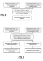
FIG. 6 depicts preferred process flows for manufacturing abrasive-blasted implants in accordance with the invention. -
FIG. 7 depicts alternative process flows for manufacturing abrasive-blasted implants in accordance with the invention. -
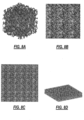
FIG. 8A depicts an illustrative, irregular (e.g., trabecular, osteo-porous, and/or osteo-derived) unit cell appropriate for additive manufacture in accordance with the invention. -
FIG. 8B shows the unit cell ofFIG. 8A repeated in a 3x3 array. -
FIG. 8C shows the unit cell ofFIG. 8A repeated in a 6x6 array. -
FIG. 8D shows an isometric view of a 9x9 array of the unit cell ofFIG. 8A . - FIG. 8E shows the unit cell of
FIG. 8A patterned across the surface of an acetabular shell. -
FIG. 8F shows the unit cell ofFIG. 8A patterned across the surface of an ALIF cage "blank." -
FIG. 9A conceptually depicts a 2-D rendering of a cubic lattice structure, with no node perturbation and no strut size randomization. -
FIG. 9B conceptually depicts a 3-D rendering of the cubic lattice structure, with no node perturbation and no strut size randomization. -
FIG. 9C conceptually depicts a 2-D rendering of a cubic lattice structure, with 20% node perturbation and no strut size randomization. -
FIG. 9D conceptually depicts a 3-D rendering of the cubic lattice structure, with 20% node perturbation and no strut size randomization. -
FIG. 9E conceptually depicts a 2-D rendering of a cubic lattice structure, with 40% node perturbation and no strut size randomization. -
FIG. 9F conceptually depicts a 3-D rendering of the cubic lattice structure, with 40% node perturbation and no strut size randomization. -
FIG. 9G conceptually depicts a 2-D rendering of a cubic lattice structure, with 20% node perturbation and 100% strut size randomization. -
FIG. 9H conceptually depicts a 3-D rendering of the cubic lattice structure, with 20% node perturbation and 100% strut size randomization. -
FIG. 9I conceptually depicts a 2-D rendering of a dodecahedron lattice structure, with no node perturbation and no strut size randomization. -
FIG. 9J conceptually depicts a 3-D rendering of the dodecahedron lattice structure, with no node perturbation and no strut size randomization. -
FIG. 9K conceptually depicts a 2-D rendering of a dodecahedron lattice structure, with 20% node perturbation and no strut size randomization. -
FIG. 9L conceptually depicts a 3-D rendering of the dodecahedron lattice structure, with 20% node perturbation and no strut size randomization. -
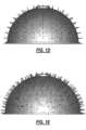
FIGS. 10A and 10B depict exemplary SEM views of porous/trabecular metal sections fabricated by additive manufacturing in accordance with the invention, but not subjected to a post-fabrication abrasive blast step. -
FIGS. 11 A and 11B depict exemplary SEM views of porous/trabecular metal sections fabricated by additive manufacturing in accordance with the invention, after being subjected to a post-fabrication abrasive blast step. -
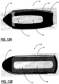
FIGS. 12A and 12B are side and top planar views of one exemplary embodiment of the posterior lumbar interbody fusion (PLIF) cage of the present invention. -
FIGS. 13A-13C are top planar, side planar, and bullet views of one exemplary embodiment of the transforaminal lumbar interbody fusion (TLIF) cage of the present invention. -
FIG. 14 is perspective, side planar, and top planar views of one exemplary embodiment of the oblique lumbar interbody fusion (OLIF) cage of the present invention. -
FIG. 15 is perspective views of the cervical cages of the present invention, both in PEEK and titanium embodiments, and incorporating a novel locking mechanism. -
FIG. 16 is top and side planar views of the cervical cage of the present invention, in the titanium embodiment and including at least one porous surface formed by the process ofFIG. 1 . -
FIG. 17 is a series of perspective views illustrating the operation of the locking mechanism ofFIG. 15 . -
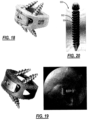
FIG. 18 is a perspective view of the ALIF cage of the present invention, in a PEEK embodiment and including a novel locking mechanism. -
FIG. 19 is a perspective view of the ALIF cage of the present invention, in a PEEK embodiment and including a novel locking mechanism. -
FIG. 20 is a perspective view of the surgical screw of the present invention, incorporating both non-porous and porous regions. - Generally speaking, and without intending to be limiting, one aspect of the invention relates to improved medical implants that include, for example, at least the following: a primary structure formed from metal; and at least one needle-populated, metallic surface portion formed on at least one exterior portion of the primary structure, the at least one surface portion located such that it engages with a patient's bone when the implant is implanted in the patient. Such needle-populated, metallic surface portions may contain, for example, a collection of at least fifty, a hundred, two hundred, five-hundred or more needles, and may be further characterized by at least one, two, three, four, five or more of the following characteristics: (a) the needles in the collection are all oriented substantially normal to the surface portion; (b) the needles in the collection are all oriented in substantially the same direction, with the direction being other than normal to the surface portion; (c) the needles in the collection are all oriented in substantially the same direction, with the direction being other than normal to the surface portion, but within 15 degrees from the normal direction; (d) the needles in the collection are all oriented in substantially the same direction, with the direction being other than normal to the surface portion, and more than 15 degrees from the normal direction; (e) the collection includes needles oriented in at least three different directions relative to the surface portion; (f) the collection includes needles oriented in at least five different directions relative to the surface portion, with all of the needles oriented within 20 degrees from the surface portion normal direction; (g) all of the needles in the collection have substantially the same height; (h) the collection includes needles of at least three different heights; (i) all of the needles in the collection have substantially the same shape; (j) the collection includes needles of at least two different shapes; (k) the needles are distributed substantially uniformly over the surface portion; (1) the needles are distributed non-uniformly over the surface portion; (m) all of the needles in the collection are anchored to the primary structure; (n) most of the needles in the collection are anchored to the primary structure; (o) most of the needles in the collection are anchored to structural elements contained within an osteo-porous, osteo-derived or trabecular coating on the at least one exterior portion of the primary structure; and/or (p) all of the needles in the collection are anchored to structural elements contained within an osteo-porous, osteo-derived or trabecular coating on the at least one exterior portion of the primary structure. The at least one exterior portion preferably includes at least one osteo-porous surface, which may comprise at least one osteo-derived surface. The at least one osteo-porous surface and the needles may be simultaneously formed by an additive manufacturing process, such as, but not limited to, EBM or DMSLS. The primary structure may comprise, for example, a dental implant, a foot-and-ankle or long-bone osteotomy wedge, an intervertebral fusion device, a tibial/femoral augment or spacer, a tibial tray portion of a knee implant, a femoral component portion of a knee implant, a primary hip implant, a revision hip implant, a hip trauma component, an acetabular cup, a hip acetabular augment, or other appropriate structure.
- Again, generally speaking, and without intending to be limiting, another aspect of the invention relates to method(s) for making a medical implants with at least one osteo-porous surface by, for example: forming at least a portion of a primary structure of the implant; and forming at least one needle-populated, metallic surface portion on at least one exterior portion of the primary structure using an additive manufacturing technique, the at least one needle-populated surface portion located such that it engages with a patient's bone when the implant is implanted in the patient.
- Other aspects of the invention relate to additional features, structures, processes and materials depicted in the figures and/or described herein.
- Referring to
FIG. 1 , the exemplary flow starts with a spongy bone sample, which is micro CT scanned to obtain 3D scan data, which is then processed into solid model data representing an osteo-porous or osteo-derived texture. This texture data is then combined with data representing the overall implant geometry to create a fabrication file for use by either of the manufacturing steps that follow. - The fabrication file may utilize any recognizable solid model specification, such as ".amf" format [see ASTM WK27506 -New Specification for Data Exchange Format for Additive Manufacturing, available at http://www.astm.org/DATABASE.CART/WORKITEMS/WK27506.htm (accessed 07-29-2011)] or ".stl" format [see Standard Data Format for Fabbers, available at http://www.ennex.com/~fabbers/StL.asp (accessed 07-29-2011)], and may be embodied on any sort of permanent storage medium (e.g., CD, CD-ROM, flash), semi-permanent (e.g., SRAM) or transitory (e.g., DRAM) storage medium, or embodied in a coded data signal.
- Additional background details concerning the fabrication of medical devices using additive techniques can be found in: J. Vehvilainen, "Process and Web Application Development of Medical Applications of Additive Manufacturing," Master's Thesis, Aalto University, School of Science, Dec. 27, 2011 (available at http://lib.tkk.fi/Dipl/2011/urnl00592.pdf (accessed 06-13-12)).
- Referring to
FIG. 1A , an additional step can be inserted that adds outwardly-protruding "needles" on the outer surface(s) of the osteo-porous and/or osteo-derived coating(s). Such needles substantially increase the coefficient of friction of the coating. Having a high coefficient of friction is clinically advantageous because it provides stronger initial fixation, which is important before bone is able to grow onto/into the porous structure. Such needles can be uniformly or non-uniformly (as shown inFIG. 1B ) distributed along the porous surface. Likewise, various shapes for the needles are possible, including rectangular (as depicted inFIG. 1B ), pyramidal, conical, tube-shaped, etc. Also, the needles need not be oriented exactly normal to the exterior surface, but are preferably oriented in a substantially normal (e.g., within +/-15 degrees from normal) orientation. Furthermore, the orientation and/or shape of all needles need not be the same, and the needles may be rendered on selected portions, or the entirety, of the exterior coated surface(s). - Utilizing these or similar techniques, one can efficiently and advantageously form (and/or finish) implants of the sort depicted herein.
- Referring to
FIG. 6 , two preferred process flows for fabricating and finishing implants using an abrasive blast are shown.FIG. 7 shows two alternative flows that employ the blasting technique as well.FIGS. 10A and 10B and11A and 11B contrastingly depict SEM images of porous implant sections that have and have not undergone an abrasive blasting step. As can be seen from the images, the non-blasted samples are mostly smooth if viewed on the 20 or 100 µrn scale, whereas the blasted samples are almost entirely rough, when viewed at similar magnification. This blast process creates a texture approximately l-20µm in scale. This is an ideal scale for microtexture because it helps osteoblasts adhere to the titanium struts. The blast material is not deposited on the strut (as an HA coating would be). It simply textures the titanium surface by erosion. - In accordance with the invention, the preferred abrasive blast process utilizes an MCD Apatitic Abrasive (Multi-phased Calcium Phosphate containing HA, TCP and other CaP phases) distributed by Hitemco Medical Applications, Inc., 160 Sweet Hollow Rd., Old Bethpage, NY 11804. The blast media has a 425 - 180 µm size range. The process utilizes a Comco AccuFlo® standard tank micro-abrasive blaster, equipped with Simoom® Technology and PowderGate® valve. Tank orifice is 0.40 inches (approx. 1 cm); Nozzle is 0.060 inches (approx. 1.52 mm); Pressure is 90 +/-5 psi (approx. 6.2 +/- 0.3 Bar). A satisfactory roughness has been achieved when the blast does not further affect the visual appearance, specifically the color and reflectivity of the device. Machined devices may require a blast touch up.
-
FIGS. 9A-9L illustratively depict the concept of slightly-irregular lattices that are ideally adapted for additive manufacturing. As shown in these figures, node perturbation refers to the location of intersecting struts. In accordance with this aspect of the invention, such intersection locations are be randomized such that the node deviates from a uniform lattice by a randomized distance. Strut size randomization refers to a deviation in cross-section dimension (e.g., strut diameter). Discrete struts in a lattice could have different cross-sectional sizes, or the struts could have a diameter gradient from one end to the other. These parameters can be randomized for greater diversity in the lattice's geometry. Such slightly-irregular lattices can be used to fabricate any sort of medical implant for which regular lattices are currently used, including, for example, those disclosed in the cited Pressacco et al. and Jones et al. applications. - Another illustrative application of the invention relates to bone fixation/fusion devices of the sort disclosed in
U.S. Pat. No. 7,922,765 and/orU.S Published Applic. No. 2011/0118841 that have been modified to include one or more needle-populated surface(s) in accordance with the teachings of the present invention. - Such fusion/fixation devices are preferably fabricated by additive techniques, may utilize multi-circular cross-sectional profiles (either uniform or tapered), and preferably include exterior needles, preferably oriented in a direction that would resist removal of the implant. Multi-circular cross-sectional profiles have the distinct advantage of not requiring one or more bore broaching steps, thus making insertion quicker and reducing patient infection risk.
- Finally, it should be understood that the novel structures disclosed and enabled by the present invention are not limited exclusively to those manufactured using additive manufacturing. Indeed, as persons skilled in the art will appreciate, other known surface modification techniques - such as, for example, Surfi-Sculpt (
U.S. Pat. No. 7,667,15 8 ) - may be used to produce the osteoporous, osteo-derived, and/or needle-containing textures of the inventive implants. - Referring now specifically to
FIGS. 2-5 , in one exemplary embodiment, the present invention provides anALIF cage 10 for use in spinal surgical procedures. More specifically, the present invention provides anALIF cage 10 that includes one or moreporous surfaces 12 that promote bony fixation. Preferably, theseporous surfaces 12 are formed via an additive manufacturing technique using a titanium alloy powder or the like (as is described in greater detail herein below), thereby providing a unitary structure and eliminating the need to use coatings or bondings for such purpose. - In general, the
ALIF cage 10 includes abody structure 14 that defines a hollowinterior portion 16 and a plurality ofports 18 through which screws 20 (FIG. 3 ) or the like are disposed, through the hollowinterior portion 16 and into adjacent bone. Optionally, the hollowinterior portion 16 is sized and configured to contain bone graft material or the like, to further enhance bony fixation. Thescrews 20 are shown at a given angle, although any suitable angle(s) for a given application may be utilized, as may any suitable number and size ofscrews 20. - Advantageously, the
ALIF cage 10 consists of a unitary structure that is substantially solid in the middle, for example, and graduates to porous at given surfaces, for example. This provides enhanced structural integrity, allows for the porosity to be carefully controlled in a given area, etc. Alternatively, there may be a relatively sharp dividing line between the solid portion and the porous portions, although it is contemplated that they are integrally formed via the additive manufacturing technique. - The following description is partially taken from
US 13/530,048 porous surfaces 12 of theALIF cage 10 are formed. - Generally speaking, and without intending to be limiting, one aspect of the present invention relates to improved medical implants that include, for example, at least the following: a primary structure formed from metal; and at least one needle-populated, metallic surface portion formed on at least one exterior portion of the primary structure, the at least one surface portion located such that it engages with a patient's bone when the implant is implanted in the patient. Such needle-populated, metallic surface portions may contain, for example, a collection of at least fifty, a hundred, two hundred, five-hundred or more needles, and may be further characterized by at least one, two, three, four, five or more of the following characteristics: (a) the needles in the collection are all oriented substantially normal to the surface portion; (b) the needles in the collection are all oriented in substantially the same direction, with the direction being other than normal to the surface portion; (c) the needles in the collection are all oriented in substantially the same direction, with the direction being other than normal to the surface portion, but within 15 degrees from the normal direction; (d) the needles in the collection are all oriented in substantially the same direction, with the direction being other than normal to the surface portion, and more than 15 degrees from the normal direction; (e) the collection includes needles oriented in at least three different directions relative to the surface portion; (f) the collection includes needles oriented in at least five different directions relative to the surface portion, with all of the needles oriented within 20 degrees from the surface portion normal direction; (g) all of the needles in the collection have substantially the same height; (h) the collection includes needles of at least three different heights; (i) all of the needles in the collection have substantially the same shape; (j) the collection includes needles of at least two different shapes; (k) the needles are distributed substantially uniformly over the surface portion; (l) the needles are distributed non-uniformly over the surface portion; (m) all of the needles in the collection are anchored to the primary structure; (n) most of the needles in the collection are anchored to the primary structure; (o) most of the needles in the collection are anchored to structural elements contained within an osteo-porous, osteo-derived or trabecular coating on the at least one exterior portion of the primary structure; and/or (p) all of the needles in the collection are anchored to structural elements contained within an osteo-porous, osteo-derived or trabecular coating on the at least one exterior portion of the primary structure. The at least one exterior portion preferably includes at least one osteo-porous surface, which may comprise at least one osteo-derived surface. The at least one osteo-porous surface and the needles may be simultaneously formed by an additive manufacturing process, such as, but not limited to, EBM or DMSLS. The primary structure may comprise, for example, the
ALIF cage 10 of the present invention, a dental implant, a foot-and-ankle or long-bone osteotomy wedge, an intervertebral fusion device, a tibial/femoral augment or spacer, a tibial tray portion of a knee implant, a femoral component portion of a knee implant, a primary hip implant, a revision hip implant, a hip trauma component, an acetabular cup, a hip acetabular augment, or other appropriate structure. - Again, generally speaking, and without intending to be limiting, another aspect of the present invention relates to method(s) for making a medical implants with at least one osteo-porous surface by, for example: forming at least a portion of a primary structure of the implant; and forming at least one needle-populated, metallic surface portion on at least one exterior portion of the primary structure using an additive manufacturing technique, the at least one needle-populated surface portion located such that it engages with a patient's bone when the implant is implanted in the patient.
- The exemplary flow starts with a spongy bone sample, which is micro CT scanned to obtain 3D scan data, which is then processed into solid model data representing an osteo-porous or osteo-derived texture. This texture data is then combined with data representing the overall implant geometry to create a fabrication file for use by either of the manufacturing steps that follow. The fabrication file may utilize any recognizable solid model specification, such as ".amf" format [see ASTM WK27506 - New Specification for Data Exchange Format for Additive Manufacturing, available at http://www.astm.org/DATABASE.CART/WORKITEMS/WK27506.htm (accessed 07-29-2011)] or ".stl" format [see Standard Data Format for Fabbers, available at http://www.ennex.com/~fabbers/StL.asp (accessed 07-29-2011)], and may be embodied on any sort of permanent storage medium (e.g., CD, CD-ROM, flash), semi-permanent (e.g., SRAM) or transitory (e.g., DRAM) storage medium, or embodied in a coded data signal.
- Additional background details concerning the fabrication of medical devices using additive techniques can be found in: J. VehvilLinen, "Process and Web Application Development of Medical Applications of Additive Manufacturing," Master's Thesis, Aalto University, School of Science, Dec. 27, 2011 (available at http://lib.tkk.fi/Dipl/201 1/urn100592.pdf (accessed 06-13-12)).
- An additional step can be inserted that adds outwardly-protruding "needles" on the outer surface(s) of the osteo-porous and/or osteo-derived coating(s). Such needles substantially increase the coefficient of friction of the coating. Having a high coefficient of friction is clinically advantageous because it provides stronger initial fixation, which is important before bone is able to grow onto/into the porous structure. Such needles can be uniformly or non-uniformly distributed along the porous surface. Likewise, various shapes for the needles are possible, including rectangular, pyramidal, conical, tube-shaped, etc. Also, the needles need not be oriented exactly normal to the exterior surface, but are preferably oriented in a substantially normal (e.g., within +/-15 degrees from normal) orientation. Furthermore, the orientation and/or shape of all needles need not be the same, and the needles may be rendered on selected portions, or the entirety, of the exterior coated surface(s).
- Utilizing these or similar techniques, one can efficiently and advantageously form (and/or finish) implants. Finally, it should be understood that the novel structures disclosed and enabled by the present invention are not limited exclusively to those manufactured using additive manufacturing. Indeed, as persons skilled in the art will appreciate, other known surface modification techniques -- such as, for example, Surfi-Sculpt (
U.S. Pat. No. 7,667,15 8 ) -- may be used to produce the osteoporous, osteo-derived, and/or needle-containing textures of the inventive implants. -
FIGS. 12A and 12B are side and top planar views of one exemplary embodiment of the posterior lumbar interbody fusion (PLIF)cage 100 of the present invention. ThePLIF cage 100 includes abody structure 102 that defines a substantially hollowinterior portion 104 and incorporates one ormore windows 106, such that graft material or the like may be disposed within thePLIF cage 100 to promote bony purchase. ThePLIF cage 100 also includes aleading edge 108 that is substantially tapered, such that thePLIF cage 100 may be easily disposed in an intervertebral space, and a trailing edge that includes atool receiving recess 110 or the like. As with all devices of the present invention, the PLIF cage 1001 may be manufactured from PEEK or a metallic material with the porous surface(s) described in detail herein. -
FIGS. 13A-13C are top planar, side planar, and bullet views of one exemplary embodiment of the transforaminal lumbar interbody fusion (TLIF)cage 200 of the present invention. TheTLIF cage 200 includes a substantially-curved body structure 202 that defines a substantially hollowinterior portion 204 and incorporates one ormore windows 206, such that graft material or the like may be disposed within theTLIF cage 200 to promote bony purchase. TheTLIF cage 200 also includes aleading edge 208 that is substantially tapered, such that theTLIF cage 200 may be easily disposed in an intervertebral space, and a trailing edge that includes atool receiving recess 210 or the like. As with all devices of the present invention, theTLIF cage 200 may be manufactured from PEEK or a metallic material with the porous surface(s) described in detail herein. -
FIG. 14 is perspective, side planar, and top planar views of one exemplary embodiment of the oblique lumbar interbody fusion (OLIF)cage 300 of the present invention. TheOLIF cage 300 includes abody structure 302 that defines a substantially hollowinterior portion 304 and incorporates one ormore windows 306, such that graft material or the like may be disposed within theOLIF cage 300 to promote bony purchase. TheOLIF cage 300 also includes aleading edge 308 that is substantially tapered, such that theOLIF cage 300 may be easily disposed in an intervertebral space, and a trailing edge that includes atool receiving recess 310 or the like. As with all devices of the present invention, theOLIF cage 300 may be manufactured from PEEK or a metallic material with the porous surface(s) described in detail herein. -
FIG. 15 is perspective views of thecervical cages 350 of the present invention, both in PEEK and titanium embodiments, and incorporating anovel locking mechanism 400. Thesecervical cages 350 are similar to the ALIF cage described in detail herein above, further including thenovel locking mechanism 400. Thenovel locking mechanism 400 includes acover plate 402 that is held in place over one of the primary cage screws using aplate screw 404. When actuated, theplate screw 404 compresses thecover plate 402 against the body structure of thecervical cage 350, driving lockingtabs 406 in the corners of thecover plate 402 into corresponding recesses manufactured into the body structure. This locks the primary cage screws into the body structure and prevents them from backing out. Advantageously, at least three points of contact are provided between thecover plate 402 and the body structure to provide the required stability. -
FIG. 16 is top and side planar views of the cervical cage of the present invention, in the titanium embodiment and including at least oneporous surface 420 formed by the process ofFIG. 1 . In this exemplary embodiment, theporous surface 420 does not cover the insertion edge and is thinner at the anterior edge to allow support material for thecover plate 402 andplate screw 404. -
FIG. 17 is a series of perspective views illustrating the operation of the locking mechanism ofFIG. 15 . -
FIG. 18 is a perspective view of the ALIF cage of the present invention, in a PEEK embodiment and including a novel locking mechanism.FIG. 19 is a perspective view of the ALIF cage of the present invention, in a PEEK embodiment and including a novel locking mechanism. These ALIF cages operates in a manner similar to the cervical cages described herein above. -
FIG. 20 is a perspective view of thesurgical screw 500 of the present invention, incorporating bothporous regions 502 andnon-porous regions 504. Specifically, in this exemplary embodiment, the porous regions are disposed at the threads to promote bony purchase. - Although the present invention is illustrated and described herein with reference to preferred embodiments and specific examples thereof, it will be readily apparent to those of ordinary skill in the art that other embodiments and examples may perform similar functions and/or achieve like results. All such equivalent embodiments and examples are within the scope of the present invention, are contemplated thereby, and are intended to be covered by the following claims.
Claims (14)
- A method for manufacturing a surgical implant device, comprising:providing a body portion; andforming one or more surfaces comprising a plurality of needles,wherein the body portion and the one or more surfaces comprising the plurality of needles are integrally formed, andwherein an exterior surface of each of the plurality of needles is roughened by abrasive blast of surgical implant device.
- The method of claim 1,
wherein the one or more surfaces comprising the plurality of needles are formed by an additive manufacturing process. - The method of claim 1,
wherein the plurality of needles are disposed substantially perpendicular to the body portion. - The method of claim 1,
wherein the plurality needles are disposed at an angle to the body portion. - The method of claim 1,
wherein the plurality of needles are disposed at an angle to the body portion within 15 degrees from the normal direction. - The method of claim 1,
wherein the plurality of needles comprise titanium. - The method of claim 1,
wherein the body portion defines a hollow interior cavity. - The method of claim 1,
wherein the body portion defines one or more ports that are configured to receive a bone screw. - The method of claim 1,
wherein the body portion defines one or more ports that are configured to allow bony ingrowth. - The method of claim 1,
wherein the plurality of needles substantially increase the coefficient of friction of the one or more c surfaces. - The method of claim 1,wherein the one or more surfaces comprise an osteo-porous or osteo-derived surface, andwherein the body portion and the one or more surfaces comprising the osteo-porous or osteo-derived surface and the plurality of needles are integrally formed.
- The method of claim 11,wherein the osteo-porous or osteo-derived surfacecomprises an irregular lattice of intersecting struts that intersects at randomly perturbed nodes,wherein some of the plurality of needles are anchored to the body portion and some of the plurality of needles are anchored to the intersecting struts of the irregular lattice of the osteo-porous or osteo-derivedsurface, andwherein the plurality of needles substantially increase the coefficient of friction of the one or more surfaces.
- A surgical implant device, comprising:a body portion; andone or more surfaces comprising a plurality of needles,wherein the body portion and the one or more surfaces comprising the plurality of needles are integrally formed, andwherein an exterior surface of each of the plurality of needles is roughened by abrasive blast of the surgical implant device.
- The surgical implant of claim 13,wherein the one or more surfaces comprise an osteo-porous or osteo-derived surface,wherein the body portion and the one or more surfaces comprising the osteo-porous or osteo-derived surface and the plurality of needles are integrally formed,wherein the osteo-porous or osteo-derived surface comprises an irregular lattice of intersecting struts that intersects at randomly perturbed nodes,wherein some of the plurality of needles are anchored to the body portion and some of the plurality of needles are anchored to the intersecting struts of the irregular lattice of the osteo-porous or osteo-derived surface, andwherein the plurality of needles substantially increase the coefficient of friction of the one or more surfaces.
Applications Claiming Priority (4)
| Application Number | Priority Date | Filing Date | Title |
|---|---|---|---|
| US201361885778P | 2013-10-02 | 2013-10-02 | |
| US201361916469P | 2013-12-16 | 2013-12-16 | |
| PCT/US2014/058759 WO2015051080A1 (en) | 2013-10-02 | 2014-10-02 | Surgical implant devices incorporating porous surfaces and a locking plate |
| EP14850170.3A EP3052037B1 (en) | 2013-10-02 | 2014-10-02 | Surgical implant devices incorporating porous surfaces and a locking plate |
Related Parent Applications (1)
| Application Number | Title | Priority Date | Filing Date |
|---|---|---|---|
| EP14850170.3A Division EP3052037B1 (en) | 2013-10-02 | 2014-10-02 | Surgical implant devices incorporating porous surfaces and a locking plate |
Publications (2)
| Publication Number | Publication Date |
|---|---|
| EP4108211A1 EP4108211A1 (en) | 2022-12-28 |
| EP4108211B1 true EP4108211B1 (en) | 2025-04-09 |
Family
ID=56291919
Family Applications (2)
| Application Number | Title | Priority Date | Filing Date |
|---|---|---|---|
| EP14850170.3A Active EP3052037B1 (en) | 2013-10-02 | 2014-10-02 | Surgical implant devices incorporating porous surfaces and a locking plate |
| EP22186653.6A Active EP4108211B1 (en) | 2013-10-02 | 2014-10-02 | Surgical implant devices incorporating porous surfaces and a locking plate |
Family Applications Before (1)
| Application Number | Title | Priority Date | Filing Date |
|---|---|---|---|
| EP14850170.3A Active EP3052037B1 (en) | 2013-10-02 | 2014-10-02 | Surgical implant devices incorporating porous surfaces and a locking plate |
Country Status (1)
| Country | Link |
|---|---|
| EP (2) | EP3052037B1 (en) |
Families Citing this family (2)
| Publication number | Priority date | Publication date | Assignee | Title |
|---|---|---|---|---|
| US11672674B2 (en) | 2017-04-19 | 2023-06-13 | Life Spine Inc. | Implant with bone screw retention |
| WO2018195260A1 (en) * | 2017-04-19 | 2018-10-25 | Life Spine Inc. (A Delaware Corporation) | Stand-alone alif spine implants |
Family Cites Families (13)
| Publication number | Priority date | Publication date | Assignee | Title |
|---|---|---|---|---|
| JP4467647B2 (en) * | 1997-02-11 | 2010-05-26 | ウォーソー・オーソペディック・インコーポレーテッド | Bone plating system |
| ATE486682T1 (en) | 2002-09-30 | 2010-11-15 | Welding Inst | METHOD FOR WORKPIECE STRUCTURE MODIFICATION |
| DE60300277T2 (en) * | 2002-11-08 | 2006-01-12 | Howmedica Osteonics Corp. | Laser generated porous surface |
| ATE496593T1 (en) * | 2003-02-06 | 2011-02-15 | Synthes Gmbh | INTERVERBARY IMPLANT |
| US20060036251A1 (en) | 2004-08-09 | 2006-02-16 | Reiley Mark A | Systems and methods for the fixation or fusion of bone |
| US8414648B2 (en) | 2004-08-09 | 2013-04-09 | Si-Bone Inc. | Apparatus, systems, and methods for achieving trans-iliac lumbar fusion |
| GB0620359D0 (en) * | 2006-10-13 | 2006-11-22 | Symmetry Medical Inc | Medical devices |
| US8275594B2 (en) * | 2006-10-30 | 2012-09-25 | The Regents Of The University Of Michigan | Engineered scaffolds for intervertebral disc repair and regeneration and for articulating joint repair and regeneration |
| US8882813B2 (en) * | 2007-10-19 | 2014-11-11 | Spinesmith Partners, L.P. | Locking mechanisms and associated methods |
| ITMO20070280A1 (en) * | 2007-09-12 | 2009-03-13 | Eurocoating S P A | METHOD FOR COATING ELEMENTS FOR PROSTHESIS AND ELEMENTS OBTAINED BY PROCEDURE |
| US20100286777A1 (en) * | 2009-05-08 | 2010-11-11 | Stryker Spine | Stand alone anterior cage |
| EP2253291B1 (en) * | 2009-05-19 | 2016-03-16 | National University of Ireland, Galway | A bone implant with a surface anchoring structure |
| GB0922339D0 (en) * | 2009-12-21 | 2010-02-03 | Mcminn Derek J W | Acetabular cup prothesis and introducer thereof |
-
2014
- 2014-10-02 EP EP14850170.3A patent/EP3052037B1/en active Active
- 2014-10-02 EP EP22186653.6A patent/EP4108211B1/en active Active
Also Published As
| Publication number | Publication date |
|---|---|
| EP3052037B1 (en) | 2022-08-24 |
| EP4108211A1 (en) | 2022-12-28 |
| EP3052037A4 (en) | 2017-06-21 |
| EP3052037A1 (en) | 2016-08-10 |
Similar Documents
| Publication | Publication Date | Title |
|---|---|---|
| US10154913B2 (en) | Surgical implant devices incorporating porous surfaces and a locking plate | |
| US10765530B2 (en) | Surgical implant devices incorporating porous surfaces | |
| JP2016525415A5 (en) | ||
| US20250241765A1 (en) | Features for implants with a reduced volumetric density of surface roughness | |
| US10624746B2 (en) | Fluid interface system for implants | |
| US10561456B2 (en) | Bone screw incorporating a porous surface formed by an additive manufacturing process | |
| US11291558B2 (en) | Dynamic implant fixation plate | |
| US9125756B2 (en) | Processes for producing regular repeating patterns on surfaces of interbody devices | |
| US9999516B2 (en) | Implant device having a non-planar surface | |
| US8758443B2 (en) | Implants with integration surfaces having regular repeating surface patterns | |
| US8758442B2 (en) | Composite implants having integration surfaces composed of a regular repeating pattern | |
| EP3024419B1 (en) | Surgical implant devices incorporating porous surfaces | |
| US11872136B2 (en) | Surgical implant devices incorporating porous surfaces and associated method of manufacture | |
| EP3052037B1 (en) | Surgical implant devices incorporating porous surfaces and a locking plate | |
| AU2017219021B2 (en) | Surgical Implant Devices Incorporating Porous Surfaces And A Locking Plate | |
| AU2014329595A1 (en) | Surgical implant devices incorporating porous surfaces and a locking plate | |
| US20250107903A1 (en) | Integral graft interbody devices |
Legal Events
| Date | Code | Title | Description |
|---|---|---|---|
| PUAI | Public reference made under article 153(3) epc to a published international application that has entered the european phase |
Free format text: ORIGINAL CODE: 0009012 |
|
| STAA | Information on the status of an ep patent application or granted ep patent |
Free format text: STATUS: THE APPLICATION HAS BEEN PUBLISHED |
|
| AC | Divisional application: reference to earlier application |
Ref document number: 3052037 Country of ref document: EP Kind code of ref document: P |
|
| AK | Designated contracting states |
Kind code of ref document: A1 Designated state(s): AL AT BE BG CH CY CZ DE DK EE ES FI FR GB GR HR HU IE IS IT LI LT LU LV MC MK MT NL NO PL PT RO RS SE SI SK SM TR |
|
| STAA | Information on the status of an ep patent application or granted ep patent |
Free format text: STATUS: REQUEST FOR EXAMINATION WAS MADE |
|
| 17P | Request for examination filed |
Effective date: 20230522 |
|
| RBV | Designated contracting states (corrected) |
Designated state(s): AL AT BE BG CH CY CZ DE DK EE ES FI FR GB GR HR HU IE IS IT LI LT LU LV MC MK MT NL NO PL PT RO RS SE SI SK SM TR |
|
| P01 | Opt-out of the competence of the unified patent court (upc) registered |
Effective date: 20230609 |
|
| GRAP | Despatch of communication of intention to grant a patent |
Free format text: ORIGINAL CODE: EPIDOSNIGR1 |
|
| STAA | Information on the status of an ep patent application or granted ep patent |
Free format text: STATUS: GRANT OF PATENT IS INTENDED |
|
| RIC1 | Information provided on ipc code assigned before grant |
Ipc: B33Y 80/00 20150101ALI20241021BHEP Ipc: B33Y 10/00 20150101ALI20241021BHEP Ipc: B22F 10/20 20210101ALI20241021BHEP Ipc: A61B 17/80 20060101ALI20241021BHEP Ipc: A61B 17/70 20060101ALI20241021BHEP Ipc: B22F 5/00 20060101ALI20241021BHEP Ipc: B22F 3/105 20060101ALI20241021BHEP Ipc: A61F 2/34 20060101ALI20241021BHEP Ipc: A61F 2/30 20060101ALI20241021BHEP Ipc: A61B 17/86 20060101ALI20241021BHEP Ipc: A61F 2/44 20060101AFI20241021BHEP |
|
| INTG | Intention to grant announced |
Effective date: 20241107 |
|
| GRAS | Grant fee paid |
Free format text: ORIGINAL CODE: EPIDOSNIGR3 |
|
| GRAA | (expected) grant |
Free format text: ORIGINAL CODE: 0009210 |
|
| STAA | Information on the status of an ep patent application or granted ep patent |
Free format text: STATUS: THE PATENT HAS BEEN GRANTED |
|
| AC | Divisional application: reference to earlier application |
Ref document number: 3052037 Country of ref document: EP Kind code of ref document: P |
|
| AK | Designated contracting states |
Kind code of ref document: B1 Designated state(s): AL AT BE BG CH CY CZ DE DK EE ES FI FR GB GR HR HU IE IS IT LI LT LU LV MC MK MT NL NO PL PT RO RS SE SI SK SM TR |
|
| REG | Reference to a national code |
Ref country code: GB Ref legal event code: FG4D |
|
| REG | Reference to a national code |
Ref country code: CH Ref legal event code: EP |
|
| REG | Reference to a national code |
Ref country code: DE Ref legal event code: R096 Ref document number: 602014091798 Country of ref document: DE |
|
| REG | Reference to a national code |
Ref country code: IE Ref legal event code: FG4D |
|
| REG | Reference to a national code |
Ref country code: NL Ref legal event code: MP Effective date: 20250409 |
|
| PG25 | Lapsed in a contracting state [announced via postgrant information from national office to epo] |
Ref country code: NL Free format text: LAPSE BECAUSE OF FAILURE TO SUBMIT A TRANSLATION OF THE DESCRIPTION OR TO PAY THE FEE WITHIN THE PRESCRIBED TIME-LIMIT Effective date: 20250409 |
|
| REG | Reference to a national code |
Ref country code: AT Ref legal event code: MK05 Ref document number: 1782871 Country of ref document: AT Kind code of ref document: T Effective date: 20250409 |
|
| PG25 | Lapsed in a contracting state [announced via postgrant information from national office to epo] |
Ref country code: FI Free format text: LAPSE BECAUSE OF FAILURE TO SUBMIT A TRANSLATION OF THE DESCRIPTION OR TO PAY THE FEE WITHIN THE PRESCRIBED TIME-LIMIT Effective date: 20250409 Ref country code: PT Free format text: LAPSE BECAUSE OF FAILURE TO SUBMIT A TRANSLATION OF THE DESCRIPTION OR TO PAY THE FEE WITHIN THE PRESCRIBED TIME-LIMIT Effective date: 20250811 Ref country code: ES Free format text: LAPSE BECAUSE OF FAILURE TO SUBMIT A TRANSLATION OF THE DESCRIPTION OR TO PAY THE FEE WITHIN THE PRESCRIBED TIME-LIMIT Effective date: 20250409 |
|
| REG | Reference to a national code |
Ref country code: LT Ref legal event code: MG9D |
|
| PG25 | Lapsed in a contracting state [announced via postgrant information from national office to epo] |
Ref country code: GR Free format text: LAPSE BECAUSE OF FAILURE TO SUBMIT A TRANSLATION OF THE DESCRIPTION OR TO PAY THE FEE WITHIN THE PRESCRIBED TIME-LIMIT Effective date: 20250710 Ref country code: NO Free format text: LAPSE BECAUSE OF FAILURE TO SUBMIT A TRANSLATION OF THE DESCRIPTION OR TO PAY THE FEE WITHIN THE PRESCRIBED TIME-LIMIT Effective date: 20250709 |
|
| PG25 | Lapsed in a contracting state [announced via postgrant information from national office to epo] |
Ref country code: PL Free format text: LAPSE BECAUSE OF FAILURE TO SUBMIT A TRANSLATION OF THE DESCRIPTION OR TO PAY THE FEE WITHIN THE PRESCRIBED TIME-LIMIT Effective date: 20250409 |
|
| PG25 | Lapsed in a contracting state [announced via postgrant information from national office to epo] |
Ref country code: BG Free format text: LAPSE BECAUSE OF FAILURE TO SUBMIT A TRANSLATION OF THE DESCRIPTION OR TO PAY THE FEE WITHIN THE PRESCRIBED TIME-LIMIT Effective date: 20250409 |
|
| PG25 | Lapsed in a contracting state [announced via postgrant information from national office to epo] |
Ref country code: HR Free format text: LAPSE BECAUSE OF FAILURE TO SUBMIT A TRANSLATION OF THE DESCRIPTION OR TO PAY THE FEE WITHIN THE PRESCRIBED TIME-LIMIT Effective date: 20250409 |
|
| PG25 | Lapsed in a contracting state [announced via postgrant information from national office to epo] |
Ref country code: AT Free format text: LAPSE BECAUSE OF FAILURE TO SUBMIT A TRANSLATION OF THE DESCRIPTION OR TO PAY THE FEE WITHIN THE PRESCRIBED TIME-LIMIT Effective date: 20250409 |
|
| PG25 | Lapsed in a contracting state [announced via postgrant information from national office to epo] |
Ref country code: RS Free format text: LAPSE BECAUSE OF FAILURE TO SUBMIT A TRANSLATION OF THE DESCRIPTION OR TO PAY THE FEE WITHIN THE PRESCRIBED TIME-LIMIT Effective date: 20250709 |
|
| PG25 | Lapsed in a contracting state [announced via postgrant information from national office to epo] |
Ref country code: IS Free format text: LAPSE BECAUSE OF FAILURE TO SUBMIT A TRANSLATION OF THE DESCRIPTION OR TO PAY THE FEE WITHIN THE PRESCRIBED TIME-LIMIT Effective date: 20250809 |
|
| PG25 | Lapsed in a contracting state [announced via postgrant information from national office to epo] |
Ref country code: LV Free format text: LAPSE BECAUSE OF FAILURE TO SUBMIT A TRANSLATION OF THE DESCRIPTION OR TO PAY THE FEE WITHIN THE PRESCRIBED TIME-LIMIT Effective date: 20250409 |
|
| PGFP | Annual fee paid to national office [announced via postgrant information from national office to epo] |
Ref country code: DE Payment date: 20250915 Year of fee payment: 12 |
|
| PGFP | Annual fee paid to national office [announced via postgrant information from national office to epo] |
Ref country code: GB Payment date: 20251024 Year of fee payment: 12 |
|
| REG | Reference to a national code |
Ref country code: DE Ref legal event code: R097 Ref document number: 602014091798 Country of ref document: DE |
|
| PG25 | Lapsed in a contracting state [announced via postgrant information from national office to epo] |
Ref country code: SM Free format text: LAPSE BECAUSE OF FAILURE TO SUBMIT A TRANSLATION OF THE DESCRIPTION OR TO PAY THE FEE WITHIN THE PRESCRIBED TIME-LIMIT Effective date: 20250409 Ref country code: DK Free format text: LAPSE BECAUSE OF FAILURE TO SUBMIT A TRANSLATION OF THE DESCRIPTION OR TO PAY THE FEE WITHIN THE PRESCRIBED TIME-LIMIT Effective date: 20250409 |
|
| PGFP | Annual fee paid to national office [announced via postgrant information from national office to epo] |
Ref country code: FR Payment date: 20251029 Year of fee payment: 12 |
|
| PG25 | Lapsed in a contracting state [announced via postgrant information from national office to epo] |
Ref country code: CZ Free format text: LAPSE BECAUSE OF FAILURE TO SUBMIT A TRANSLATION OF THE DESCRIPTION OR TO PAY THE FEE WITHIN THE PRESCRIBED TIME-LIMIT Effective date: 20250409 |
|
| PG25 | Lapsed in a contracting state [announced via postgrant information from national office to epo] |
Ref country code: EE Free format text: LAPSE BECAUSE OF FAILURE TO SUBMIT A TRANSLATION OF THE DESCRIPTION OR TO PAY THE FEE WITHIN THE PRESCRIBED TIME-LIMIT Effective date: 20250409 |
|
| PG25 | Lapsed in a contracting state [announced via postgrant information from national office to epo] |
Ref country code: SK Free format text: LAPSE BECAUSE OF FAILURE TO SUBMIT A TRANSLATION OF THE DESCRIPTION OR TO PAY THE FEE WITHIN THE PRESCRIBED TIME-LIMIT Effective date: 20250409 |
|
| PG25 | Lapsed in a contracting state [announced via postgrant information from national office to epo] |
Ref country code: IT Free format text: LAPSE BECAUSE OF FAILURE TO SUBMIT A TRANSLATION OF THE DESCRIPTION OR TO PAY THE FEE WITHIN THE PRESCRIBED TIME-LIMIT Effective date: 20250409 |
|
| PG25 | Lapsed in a contracting state [announced via postgrant information from national office to epo] |
Ref country code: RO Free format text: LAPSE BECAUSE OF FAILURE TO SUBMIT A TRANSLATION OF THE DESCRIPTION OR TO PAY THE FEE WITHIN THE PRESCRIBED TIME-LIMIT Effective date: 20250409 |
|
| PLBE | No opposition filed within time limit |
Free format text: ORIGINAL CODE: 0009261 |
|
| STAA | Information on the status of an ep patent application or granted ep patent |
Free format text: STATUS: NO OPPOSITION FILED WITHIN TIME LIMIT |
|
| REG | Reference to a national code |
Ref country code: CH Ref legal event code: L10 Free format text: ST27 STATUS EVENT CODE: U-0-0-L10-L00 (AS PROVIDED BY THE NATIONAL OFFICE) Effective date: 20260218 |
|
| 26N | No opposition filed |
Effective date: 20260112 |