EP4107457B1 - Tempering system - Google Patents
Tempering system Download PDFInfo
- Publication number
- EP4107457B1 EP4107457B1 EP21707609.0A EP21707609A EP4107457B1 EP 4107457 B1 EP4107457 B1 EP 4107457B1 EP 21707609 A EP21707609 A EP 21707609A EP 4107457 B1 EP4107457 B1 EP 4107457B1
- Authority
- EP
- European Patent Office
- Prior art keywords
- air
- annealing
- temperature control
- chamber
- exhaust air
- Prior art date
- Legal status (The legal status is an assumption and is not a legal conclusion. Google has not performed a legal analysis and makes no representation as to the accuracy of the status listed.)
- Active
Links
- 238000005496 tempering Methods 0.000 title description 41
- 238000005192 partition Methods 0.000 claims description 32
- 238000009423 ventilation Methods 0.000 claims description 20
- 238000010438 heat treatment Methods 0.000 claims description 19
- 238000001816 cooling Methods 0.000 claims description 10
- 238000011144 upstream manufacturing Methods 0.000 claims description 10
- 230000003014 reinforcing effect Effects 0.000 claims description 6
- 230000001143 conditioned effect Effects 0.000 claims description 4
- 125000004122 cyclic group Chemical group 0.000 claims description 4
- 238000001914 filtration Methods 0.000 claims description 2
- 238000000137 annealing Methods 0.000 claims 46
- 238000007599 discharging Methods 0.000 claims 2
- 230000000284 resting effect Effects 0.000 claims 1
- 238000009826 distribution Methods 0.000 description 11
- 239000007789 gas Substances 0.000 description 11
- 238000009413 insulation Methods 0.000 description 7
- 238000000605 extraction Methods 0.000 description 6
- 230000002787 reinforcement Effects 0.000 description 6
- 238000009434 installation Methods 0.000 description 5
- 238000012423 maintenance Methods 0.000 description 5
- 230000005484 gravity Effects 0.000 description 3
- 238000004140 cleaning Methods 0.000 description 2
- 230000003750 conditioning effect Effects 0.000 description 2
- UGFAIRIUMAVXCW-UHFFFAOYSA-N Carbon monoxide Chemical compound [O+]#[C-] UGFAIRIUMAVXCW-UHFFFAOYSA-N 0.000 description 1
- 229910000831 Steel Inorganic materials 0.000 description 1
- 238000004887 air purification Methods 0.000 description 1
- 230000006735 deficit Effects 0.000 description 1
- 238000007791 dehumidification Methods 0.000 description 1
- 239000003546 flue gas Substances 0.000 description 1
- 239000012530 fluid Substances 0.000 description 1
- 239000012535 impurity Substances 0.000 description 1
- 239000002184 metal Substances 0.000 description 1
- 238000002156 mixing Methods 0.000 description 1
- 230000003647 oxidation Effects 0.000 description 1
- 238000007254 oxidation reaction Methods 0.000 description 1
- 230000001172 regenerating effect Effects 0.000 description 1
- 230000001105 regulatory effect Effects 0.000 description 1
- 230000000087 stabilizing effect Effects 0.000 description 1
- 239000010959 steel Substances 0.000 description 1
- 238000009827 uniform distribution Methods 0.000 description 1
- XLYOFNOQVPJJNP-UHFFFAOYSA-N water Substances O XLYOFNOQVPJJNP-UHFFFAOYSA-N 0.000 description 1
- 230000003313 weakening effect Effects 0.000 description 1
Images


Classifications
-
- F—MECHANICAL ENGINEERING; LIGHTING; HEATING; WEAPONS; BLASTING
- F26—DRYING
- F26B—DRYING SOLID MATERIALS OR OBJECTS BY REMOVING LIQUID THEREFROM
- F26B15/00—Machines or apparatus for drying objects with progressive movement; Machines or apparatus with progressive movement for drying batches of material in compact form
- F26B15/10—Machines or apparatus for drying objects with progressive movement; Machines or apparatus with progressive movement for drying batches of material in compact form with movement in a path composed of one or more straight lines, e.g. compound, the movement being in alternate horizontal and vertical directions
- F26B15/12—Machines or apparatus for drying objects with progressive movement; Machines or apparatus with progressive movement for drying batches of material in compact form with movement in a path composed of one or more straight lines, e.g. compound, the movement being in alternate horizontal and vertical directions the lines being all horizontal or slightly inclined
-
- F—MECHANICAL ENGINEERING; LIGHTING; HEATING; WEAPONS; BLASTING
- F26—DRYING
- F26B—DRYING SOLID MATERIALS OR OBJECTS BY REMOVING LIQUID THEREFROM
- F26B21/00—Arrangements or duct systems, e.g. in combination with pallet boxes, for supplying and controlling air or gases for drying solid materials or objects
- F26B21/004—Nozzle assemblies; Air knives; Air distributors; Blow boxes
-
- F—MECHANICAL ENGINEERING; LIGHTING; HEATING; WEAPONS; BLASTING
- F26—DRYING
- F26B—DRYING SOLID MATERIALS OR OBJECTS BY REMOVING LIQUID THEREFROM
- F26B21/00—Arrangements or duct systems, e.g. in combination with pallet boxes, for supplying and controlling air or gases for drying solid materials or objects
- F26B21/02—Circulating air or gases in closed cycles, e.g. wholly within the drying enclosure
- F26B21/04—Circulating air or gases in closed cycles, e.g. wholly within the drying enclosure partly outside the drying enclosure
-
- F—MECHANICAL ENGINEERING; LIGHTING; HEATING; WEAPONS; BLASTING
- F26—DRYING
- F26B—DRYING SOLID MATERIALS OR OBJECTS BY REMOVING LIQUID THEREFROM
- F26B3/00—Drying solid materials or objects by processes involving the application of heat
- F26B3/02—Drying solid materials or objects by processes involving the application of heat by convection, i.e. heat being conveyed from a heat source to the materials or objects to be dried by a gas or vapour, e.g. air
- F26B3/04—Drying solid materials or objects by processes involving the application of heat by convection, i.e. heat being conveyed from a heat source to the materials or objects to be dried by a gas or vapour, e.g. air the gas or vapour circulating over or surrounding the materials or objects to be dried
-
- F—MECHANICAL ENGINEERING; LIGHTING; HEATING; WEAPONS; BLASTING
- F26—DRYING
- F26B—DRYING SOLID MATERIALS OR OBJECTS BY REMOVING LIQUID THEREFROM
- F26B2210/00—Drying processes and machines for solid objects characterised by the specific requirements of the drying good
- F26B2210/12—Vehicle bodies, e.g. after being painted
Definitions
- the present invention relates to a tempering system for tempering workpieces, in particular for heating and/or cooling vehicle bodies.
- tempering systems have a tempering chamber through which the workpieces can be conveyed along a conveying direction.
- an air supply system for supplying air to the tempering chamber, an exhaust air system for removing exhaust air from the tempering chamber and one or more recirculation systems for circulating at least part of the air guided in the tempering chamber are usually provided.
- the supply air system and the exhaust air system are usually coupled with each other, in particular in order to be able to transfer heat from the exhaust air to the supply air.
- the disadvantage here can be that a complex duct system and/or a large amount of space is required. Examples from the prior art are disclosed, for example, in US2014/352169 A1 , EP 2 738 501 A2 , EN 10 2015 003856 A1 , US 2013/014406 A1 , US 2019/389434 A1 , EP 0 047 432 A1 , EN 10 2015 214706 A1 and EP 0 268 691 A1 .
- the present invention is based on the object of providing a temperature control system which has a reduced installation effort and a smaller space requirement.
- the tempering system for tempering workpieces is in particular a tempering system for heating and/or cooling vehicle bodies.
- the tempering system comprises a tempering chamber through which the workpieces can be conveyed along a conveying direction. Furthermore, the temperature control system comprises an air supply system for supplying air to the temperature control room and/or an exhaust air system for removing exhaust air from the temperature control room.
- the temperature control system comprises one or more recirculation systems for circulating at least part of the air in the temperature control room.
- Reduced installation effort and/or reduced space requirements can result, for example, if the supply air system and the exhaust air system are arranged spatially separate from each other.
- the supply air system and the exhaust air system are spaced apart from each other along the conveying direction.
- the supply air system and the exhaust air system preferably do not have any components that overlap along the conveying direction or are otherwise in direct spatial connection or operative connection.
- the supply air system and the exhaust air system have fans that are different from one another and/or can be operated independently of one another.
- One or more recirculation systems are arranged with respect to the conveying direction between the supply air system on the one hand and the exhaust air system on the other.
- the one or more recirculation systems are arranged along the conveying direction between the supply air system and the exhaust air system.
- the supply air system and the exhaust air system are arranged at opposite ends of the temperature control room.
- the one or more air circulation systems air can be taken from the temperature control room and at least partially fed back into the temperature control room.
- the one or more air circulation systems each comprise one or more fans, which are designed in particular as cascade fans.
- the one or more recirculation systems do not necessarily serve to guide the air in a closed circuit. Rather, “circulation” is preferably understood to mean any type of air removal from the tempering room and renewed air supply to the tempering room, especially when the air removal and the air supply take place at different points along the conveying direction.
- the supply air system, the exhaust air system and the one or more recirculation air systems are each assigned to different temperature control room sections of the temperature control room, in particular with regard to the respective air supply and/or air discharge.
- the temperature control system comprises a plurality of temperature control system sections arranged successively along the conveying direction, which are formed in particular by temperature control system modules.
- each temperature control system section is assigned exactly one or more temperature control room sections.
- each temperature control system section forms or comprises exactly one or more temperature control room sections.
- Each temperature control system section is preferably assigned to exactly one supply air system, exactly one exhaust air system and/or exactly one recirculation air system.
- temperature control system sections are each assigned exclusively to a supply air system or exclusively to an exhaust air system or exclusively to a recirculation system.
- the supply air system, the exhaust air system and the one or more recirculation systems each comprise one or more fans, in particular for driving an air flow.
- the supply air system, the exhaust air system and the one or more recirculation systems preferably each comprise independent ducts and/or ducts for connecting them to the temperature control room.
- the supply air system and the exhaust air system are connected to each other by means of a return duct, whereby the return duct extends in particular past one or more recirculation systems.
- exhaust air from the exhaust air system can be mixed with the supply air in the supply air system as required.
- an adjustable, controllable and/or adjustable portion of the exhaust air can be fed into the supply air system via the return duct.
- the supply air can be supplied with unconditioned or conditioned hall air and/or hot air from a heating device, for example fresh air from a clean gas-heated fresh air heat exchanger.
- Hot air can also be provided, for example, by means of a hot water register or another heating device, for example a thermal exhaust air purification device.
- a fresh air heat exchanger is oversized so that it can condition more than just one gas volume flow required for a dryer section of the temperature control room, so that in particular a partial volume flow of a total gas volume flow conditioned by the fresh air heat exchanger, in particular in the form of hot fresh air, can be fed to a cooling section of the temperature control chamber.
- One or more heat exchangers which would in particular be assigned to the cooling section of the temperature control chamber, are preferably dispensable as a result.
- the supply air system, the exhaust air system and/or one or more recirculation systems are preferably arranged laterally next to the temperature control room and/or horizontally adjacent to the temperature control room or to a housing surrounding the temperature control room.
- the supply air system, the exhaust air system and/or the one or more recirculation systems are directly adjacent to a housing wall of a housing of the temperature control room or are integrated into the housing of the temperature control room.
- the supply air system, the exhaust air system and/or the one or more recirculation systems are located on an outer side, in particular an outer wall, of a housing surrounding the temperature control chamber, directly adjacent to the housing.
- a fluid connection is then preferably established or can be established between the supply air system, the exhaust air system or the one or more recirculation systems on the one hand and an interior of the housing, in particular the temperature control chamber.
- the supply air system, the exhaust air system and/or the one or more recirculation air systems rest essentially completely on a floor on which the housing that surrounds the temperature control room also rests.
- a separate support structure for accommodating the supply air system, the exhaust air system and/or the one or more recirculation air systems is then preferably unnecessary.
- air from at least one temperature control chamber section can be removed from the temperature control chamber and fed to one or more further temperature control chamber sections, in particular to temperature control chamber sections preceding or following in the conveying direction.
- air in a floor area of at least one temperature control room section can be extracted.
- air can be supplied to a ceiling area of an interior space surrounded by the housing, in particular to one or more pressure chambers.
- At least a first filter stage is integrated into the supply air system and/or the recirculation air system or arranged in the supply air system and/or the recirculation air system.
- At least a second filter stage is preferably arranged within a housing surrounding the temperature control chamber.
- the at least one second filter stage is in particular a filter stage close to the nozzle, which is arranged in particular upstream with respect to a flow direction of the air and thus in front of one or more nozzles for supplying air to the temperature control chamber.
- the at least one first filter stage is preferably a coarse filter stage, which for example meets filter class D4 at most. This makes it possible to achieve a large air throughput with a low pressure loss, especially if the size of the at least one first filter stage is limited due to spatial conditions.
- the at least one second filter stage is preferably a fine filter stage, which in particular has filter class F5 or finer. This makes it possible to remove in particular impurities from the air stream which have passed through the at least one first filter stage.
- the at least one second filter stage is arranged in particular within the housing surrounding the temperature control chamber and is formed, for example, by several filter mats.
- the at least one second filter stage can thus preferably be designed to have a large surface area, so that the finer filter class also generates a preferably low pressure loss.
- the at least one second filter stage is arranged in particular between the at least one pressure chamber and the temperature control chamber.
- one or more, in particular all, filter stages are arranged exclusively within the housing surrounding the temperature control chamber.
- This one filter stage or these several filter stages then preferably have individual or several or all features of a filter stage referred to as the "first filter stage” and/or individual or several or all features of a filter stage referred to as the "second filter stage”.
- the supply air system, the exhaust air system and/or the one or more recirculation systems are arranged on one side on or in a side wall of a housing of the temperature control room.
- the supply air system, the exhaust air system and/or the one or more recirculation systems are arranged on or in the same side wall of the housing of the temperature control room.
- Only one or more distribution ducts of the supply air system, the exhaust air system and/or the one or more recirculation air systems preferably run above the temperature control chamber, in particular above the housing or within the housing.
- the tempering room is or forms in particular a tempering tunnel.
- a supply air duct for the intake of supply air and/or an exhaust air duct for the discharge of exhaust air is/are designed as a ventilation tower, wherein the respective ventilation tower rests on a floor and/or extends vertically upwards from a floor, in particular free of flow deflections and/or free of support structures, preferably free of external and/or separate support structures.
- one or both ventilation towers each have at least one lateral access opening, in particular a flap.
- a section of the respective ventilation tower having the access opening is then preferably reinforced by means of a reinforcing structure.
- the reinforcing structure can in particular be an insertable or pluggable stiffening ring. Such a reinforcing structure makes it possible to dispense with additional, in particular external, support structures or load-bearing structures for stabilizing the respective ventilation tower.
- the tempering system comprises a conveying device by means of which the workpieces can be conveyed through the tempering chamber in a longitudinal orientation thereof.
- the tempering system may comprise a conveying device by means of which the workpieces can be conveyed through the tempering chamber in a transverse orientation thereof.
- a longitudinal alignment is in particular an alignment of the workpieces such that a workpiece longitudinal axis, for example a vehicle longitudinal axis, is aligned parallel to the conveying direction when the workpieces are conveyed along the conveying direction.
- a longitudinal axis of the workpiece is preferably aligned transversely to the conveying direction, in particular perpendicular to the conveying direction, during the conveying of the workpiece.
- the longitudinal axis of the workpiece is preferably aligned horizontally or forms an angle of no more than approximately 30°, preferably no more than approximately 10°, with the horizontal.
- one or more intake openings are provided in a floor area of the temperature control system for the recirculation system and/or the exhaust air system.
- supply air and/or circulated air can be supplied to the temperature control room, in particular exclusively, via one or more pressure chambers of the temperature control system arranged only on one side, in particular on the same side of the temperature control room.
- a pressure chamber is formed on both sides of the temperature control chamber, through which the air can be introduced into the temperature control chamber.
- the two pressure chambers are preferably fluidically connected to one another by means of a connecting channel and/or connecting chamber.
- At least one partition wall separating the tempering chamber on the one hand and the one or more pressure chambers on the other hand is adapted at least in sections to a contour of the workpiece to be treated. It can be advantageous if the temperature control system comprises several temperature control system sections, wherein each temperature control system section corresponds to a holding position of the workpieces in a cyclic conveying operation of a conveying device of the temperature control system.
- connecting channel and/or the connecting space is arranged inside a housing that surrounds the temperature control space.
- An arrangement outside the housing is also conceivable.
- the temperature control system is to have as short an overall length as possible along the conveying direction, it can be provided that the axis of rotation of one or more fans of the supply air system, the exhaust air system and/or the one or more recirculation air systems is/are aligned perpendicular to the conveying direction. This means that a removal space extending laterally away from the temperature control system can be used for maintenance purposes.
- an alignment of the rotation axis of the one or more fans running parallel to the conveying direction can be selected. This makes it possible to minimize the space required for maintenance purposes on one or both sides of the temperature control system.
- the optimized arrangement and/or design of the supply air system, the exhaust air system and/or the one or more recirculation systems means that a separate support structure, in particular a steel structure, is not required. In addition, this preferably allows a high degree of pre-assembly to be achieved. Furthermore, the temperature control system can preferably be implemented cost-effectively and with little effort.
- a pressure chamber is formed on each side of the temperature control chamber, via which the air can be introduced into the temperature control chamber, wherein the two pressure chambers are fluidly connected to one another by means of a connecting channel and/or connecting chamber, wherein the connecting channel and/or the connecting chamber is arranged within a housing which surrounds the temperature control chamber.
- the temperature control system is a temperature control system for heating vehicle bodies.
- the one or more recirculation systems are or include, in particular, heating systems for heating the air.
- the one or more recirculation systems may also be or include cooling systems for cooling the air.
- one or more heat exchangers can be provided for heating or cooling the air circulated by means of the one or more recirculation systems.
- the housing is essentially cuboid-shaped.
- the housing preferably comprises an outer wall which at least partially forms or comprises a thermal insulation region, in particular for thermally insulating an interior of the housing from an environment thereof.
- the connecting channel and/or the connecting space is completely within an interior space of the Housing, in particular thermally insulated from an environment of the housing by means of the thermal insulation region.
- connecting channel and/or the connecting space is delimited by an outer wall of the housing, in particular a thermal insulation area of the outer wall of the housing, and/or by a partition wall delimiting the temperature control space.
- the connecting channel and/or the connecting space is delimited by the partition wall, in particular with respect to the downward direction of gravity. With respect to the upward direction of gravity, the connecting channel and/or the connecting space is preferably delimited by the outer wall, in particular a ceiling wall of the housing.
- the connecting channel and/or connecting space preferably extends above the temperature control space, in particular directly above the temperature control space.
- the connecting channel and/or connecting space fills a spatial area within the housing which lies in a vertical projection above the temperature control space.
- the connecting channel and/or connecting space is formed by a spatial area within the housing which lies in a vertical projection above the temperature control space.
- the connecting channel and/or connecting space has a length along the conveying direction which corresponds to at least approximately twice, preferably at least approximately five times, in particular at least approximately ten times, a height of the connecting channel and/or the connecting space.
- the height is in particular an extension in the vertical direction.
- the connecting channel and/or connecting space has a width in the horizontal direction and perpendicular to the conveying direction which corresponds to at least approximately twice, preferably at least approximately four times, in particular at least approximately eight times, a height of the connecting channel and/or the connecting space.
- the dimensioning of the connecting channel and/or connecting space described above makes it possible to achieve efficient air flow within the housing with minimized pressure loss.
- a partition wall separates the temperature control chamber from at least one of the pressure chambers and/or from the connecting channel and/or connecting chamber.
- partition wall is made up of several parts.
- the partition wall comprises a ceiling partition wall separating the temperature control chamber from the connecting duct and/or the connecting chamber.
- the partition wall comprises one or more side partition walls, each of which separates a pressure chamber from the temperature control chamber and/or each of which has one or more inlet openings for supplying air from the respective pressure chamber to the temperature control chamber.
- One or more inlet openings are provided in particular with one or more nozzles or nozzle receptacles.
- the partition wall comprises one or more filter partition walls, each of which forms a filter stage within the temperature control chamber and/or between a pressure chamber and the temperature control chamber.
- the one or more filter partition walls form, in particular, fine filter stages.
- the partition wall comprises one or more distribution spaces, which are each arranged and/or formed in particular between a filter partition wall of the partition wall and a side partition wall of the partition wall.
- the one or more filter partitions each comprise in particular one or more receptacles for one or more filter elements, for example filter mats.
- the one or more distribution chambers serve in particular to uniformly supply the air flowing from the pressure chambers through the one or more filter elements to the one or more inlet openings.
- one or more of the one or more recirculation systems each comprise a heating device by means of which at least part of the air guided in the temperature control chamber can be heated.
- the heating device can in particular comprise a heat exchanger, by means of which heat can be transferred from a heat transfer medium to at least part of the air fed into the temperature control chamber.
- the heat transfer can occur directly or indirectly.
- clean gas heating can be provided with a decentralized heat exchanger.
- one or more recirculation systems can each be assigned a clean gas heat exchanger, with the help of which heat is transferred from a clean gas (heating gas) to the air to be supplied to the temperature control room.
- a clean gas heating system can be provided by means of a central heat exchanger.
- one or more of the recirculation systems can be provided with a hot gas flap (hot air flap), by means of which hot gas from a central heat exchanger can be mixed in a controlled and/or regulated manner with the air circulated by the respective recirculation system.
- a hot gas flap hot air flap
- a burner heater can be provided, with one or more of the recirculation systems each being provided with its own burner for directly or indirectly heating the air.
- the air used for the respective burner can be fresh air, in particular hall air.
- air from the temperature control room can be used to operate the burner, in particular exhaust air from the exhaust air system, with the resulting burner flue gas preferably being fed to a regenerative thermal oxidation system for further exhaust gas aftertreatment, for example.
- a burner serves to completely clean the exhaust air. This can be provided in particular in the case of a modular thermal exhaust gas cleaning device, especially if the burner serves both to provide heating energy and to clean the exhaust air.
- the supply air system, the exhaust air system and/or the one or more recirculation systems each comprise one or more guide elements, in particular guide plates, for influencing a flow.
- Influencing the flow can be particularly advantageous if the supply air system, the exhaust air system and/or one or more recirculation systems are located laterally next to the temperature control room and/or in the horizontal direction are arranged adjacent to the temperature control chamber or to a housing surrounding the temperature control chamber.
- the supply air system, the exhaust air system and/or one or more recirculation systems are located laterally next to the temperature control room and/or in the horizontal direction are arranged adjacent to the temperature control chamber or to a housing surrounding the temperature control chamber.
- the exhaust air system and/or one or more recirculation air systems are arranged to the side of the temperature control chamber and/or horizontally adjacent to the temperature control chamber or to a housing surrounding the temperature control chamber, it can also be advantageous if air discharged from the temperature control chamber is sucked in and/or supplied via one or more guide elements, in particular guide plates, which extend at least largely in the horizontal direction and/or deflect in the vertical direction, wherein the air is then distributed to one or more filter elements and/or to one or more heat exchangers, for example by means of one or more guide elements, in particular guide plates, which extend at least largely in the vertical direction and/or deflect in the horizontal direction.
- guide elements in particular guide plates
- At least one distributor structure is arranged upstream, in particular directly upstream, of one or more filter elements and/or upstream, in particular directly upstream, of one or more heat exchangers, which in particular each comprises one or more guide elements or is formed therefrom.
- one or more guide elements are formed completely or in sections uniformly and/or continuously curved, whereby preferably a gentle flow deflection or flow diversion can be achieved, in particular while avoiding or minimizing turbulence.
- a guide element is in particular an element different from a channel or other spatially limiting flow guide.
- a guide element serves to influence the flow within a flow channel and/or flow space.
- connecting channel and/or the connecting space comprise one or more guide elements for influencing a flow within the connecting channel and/or the connecting space.
- the one or more guide elements preferably extend at least approximately over an entire height of the connecting channel and/or the connecting space.
- the one or more guide elements extend over at least approximately 10%, preferably at least approximately 30%, for example at least approximately 50%, of an entire length of a respective connecting channel and/or connecting space along the conveying direction.
- the one or more guide elements preferably serve to deflect and/or distribute the air flowing into the connecting channel and/or connecting space transversely to the inflow direction.
- the air flows into the connecting channel and/or connecting space essentially perpendicular to the conveying direction and is then deflected by means of one or more guide elements, in particular in a direction which has an angle of less than 45°, preferably less than 20°, with the conveying direction.
- the entire length the connecting channel and/or connecting space along the conveying direction can be used to distribute the incoming air to one or both pressure spaces.
- One or more guide elements are preferably vertically deflecting guide elements, in particular guide plates.
- one or more guide elements are guide elements that deflect in the horizontal direction, in particular guide plates.
- one or more guide elements each have one or more through-openings. This preferably allows air distribution to be optimized by means of the one or more guide elements.
- one or more guide elements are designed as perforated plates or each comprise at least one perforated plate.
- one or more guide elements are arranged with respect to a transverse direction running horizontally and perpendicular to the conveying direction between two guide regions of the conveying device extending along the conveying direction, in particular in a spatial region located above the tempering chamber or below the tempering chamber.
- a guide region of the conveying device is formed in particular by a rail extending along the conveying direction and/or by a plurality of roller elements or guide elements arranged one after the other along the conveying direction.
- the one or more recirculation systems each have one or more fans and/or one or more heating devices and/or one or more cooling devices and/or each comprise independent channels and/or feedthroughs for connection to the temperature control room.
- each air circulation system is assigned exactly one fan, by means of which air can be sucked in from the temperature control chamber and fed from one side of the housing surrounding the temperature control chamber into the interior of the housing.
- the air which is preferably fed in the ceiling area, is preferably distributed to both pressure chambers arranged on both sides of the temperature control chamber via the connecting duct and/or connecting chamber and fed to the temperature control chamber via the pressure chambers.
- the air is discharged from the temperature control room essentially centrally in a respective temperature control system section with respect to the conveying direction. This can preferably minimize air exchange or other impairment between adjacent temperature control system sections.
- the air is discharged from the respective tempering system section between two cycle positions (cycles; holding positions) at which the workpieces are stopped for one cycle. This preferably minimizes an undesirable influence of the air discharge on the tempering of the workpieces.
- the extraction and/or removal of the air from the tempering chamber takes place between two cycle positions. This can preferably generate an optimized convection flow between the cycle positions. Furthermore, the extraction and/or removal can preferably take place completely outside the individual spatial areas in which the workpieces are stopped for a cycle. This in turn preferably enables a flexible and/or restriction-free arrangement of nozzles over the entire individual spatial areas in which the workpieces are stopped for one cycle.
- space can preferably be created for an arrangement of nozzles for supplying air to the tempering chamber, distributed along the conveying direction over an entire cycle position (cycle; stopping position; body length/stopping space length). This preferably enables uniform tempering of the workpieces.
- a particularly compact design of the temperature control system can be achieved.
- this can be used to accommodate a temperature control system with two temperature control spaces that run parallel to each other at least in sections in a small space.
- the temperature control system comprises two temperature control rooms which run parallel to one another at least in sections and to which different and/or independent recirculation systems are assigned.
- two housings surrounding the temperature control chambers are directly adjacent to one another and/or are formed at least in sections by the same walls, in particular a common outer wall, which then forms an intermediate wall.
- each temperature control room is arranged on an outside of the housing surrounding this temperature control room, whereby these The outside is arranged facing away from the other housing.
- the two temperature control rooms are thus arranged between the recirculation systems in a direction that runs horizontally and perpendicular to the conveying direction.
- one or more conveying devices can be provided for conveying the workpieces through a temperature control chamber.
- a chain conveyor and/or a roller conveyor can be provided as a conveying device.
- Rail conveyors and/or ground-based transport systems, in particular free-moving driverless transport systems, can also be provided.
- continuous conveying can also be provided.
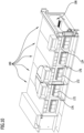
- the first embodiment of a tempering system designated as a whole by 100, shown in FIG. 1 serves in particular for tempering workpieces 102, for example vehicle bodies 104 (see in this regard the Fig. 18 shown fourth embodiment).
- a tempering system 100 comprises in particular a tempering chamber 106 through which the workpieces 102 can be conveyed along a conveying direction 110 by means of a conveying device 108.
- the temperature control chamber 106 is in particular surrounded by a housing 112, which is, for example, essentially cuboid-shaped.
- the air in the temperature control chamber 106 is preferably itself tempered, in particular conditioned, for tempering the workpieces 102. For example, cooling and/or heating of the air is provided.
- the temperature control system 100 comprises an air supply system 114, by means of which air supply, in particular tempered fresh air, can be supplied to the temperature control room 106.
- the air supply system 114 comprises in particular an air supply duct 116, which is designed, for example, as a ventilation tower 118 and serves to suck in air above a hall roof.
- the supply air system 114 further comprises a fan 120 for driving the air and a distribution channel 122, by means of which the air can be distributed to one or two pressure chambers 124 within the housing 122 in order to ultimately be supplied to the temperature control chamber 106 via the pressure chambers 124 (see the Fig. 3 to 6 ).
- Humidification and/or dehumidification of the air can also be optionally provided by means of appropriate conditioning devices.
- the temperature control system 100 further comprises a recirculation system 130, which in particular comprises at least one fan 120 and serves to remove air from the temperature control chamber 106 and to supply it again to the temperature control chamber 106.
- a recirculation system 130 which in particular comprises at least one fan 120 and serves to remove air from the temperature control chamber 106 and to supply it again to the temperature control chamber 106.
- the exhaust air system 132 further comprises a fan 120, by means of which air can be extracted from the temperature control chamber 106 and released into the environment.
- a return duct 138 can also be provided, by means of which a connection can be established between the exhaust air duct 134 of the exhaust air system 132 and the supply air duct 116 of the supply air system 114.
- exhaust air can be mixed with the supply air via the return channel 138.
- a flap and/or a valve device can be provided together with a suitable control and/or regulation in order to control and/or regulate the mixing of a predetermined exhaust air flow with the supply air.
- the temperature control system 100 can be divided into several temperature control system sections 140, wherein each temperature control system section 140 forms, for example, a temperature control system module.
- the supply air system 114 is preferably assigned to a temperature control system section 140.
- the exhaust air system 132 is preferably assigned to a further temperature control system section 140.
- the supply air system 114 and the exhaust air system 132 are preferably arranged at opposite ends of the temperature control system 100 in temperature control system sections 140.
- the recirculation system 130 is in particular assigned to or arranged on one or more temperature control system sections 140, which are arranged between the supply air system 114 and the exhaust air system 132.
- the fans 120 of the supply air system 114, the recirculation air system 130 and/or the exhaust air system 132 are preferably aligned such that their axes of rotation 142 run essentially parallel to the conveying direction 110.
- An installation space and/or maintenance space for the fans 120 thus extends essentially parallel to the conveying direction 110 away from the respective fan 120, whereby the space required laterally for the maintenance of the temperature control system 100 can be minimized.
- the following components are preferably arranged in succession in the supply air system 114, starting from one end of the temperature control system 100 along the conveying direction 110: first, the fan 120 is provided, which is followed along the conveying direction 110 by one or more heat exchangers 128 and/or one or more filter stages 126. This is then followed along the conveying direction 110 by a support area 144 for supporting the supply air duct 116, which is designed as a ventilation tower 114, for example.
- the temperature control system 100 can preferably be made particularly short, since no further components are required along the conveying direction 110 beyond the temperature control chamber 106. Rather, the air is sucked in in an intermediate area spaced from the end of the temperature control chamber 106, whereby the air can still be supplied to the temperature control chamber 106 at the immediate end of the temperature control chamber 106.
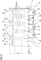
- the second embodiment of a temperature control system 100 shown in the Fig. 1 to 7 illustrated first embodiment essentially in that the temperature control system 100 is very compact and has a shorter length, particularly in the conveying direction 110.
- the resulting reduced installation space along the conveying direction 110 is compensated in this embodiment in particular by the fact that the rotation axes 142 of the fans 120 (see in particular Fig. 11 ) are not aligned parallel to the conveying direction 110, but perpendicular to it.
- the individual components of the supply air system 114, the recirculation air system 130 and the exhaust air system 132 can thereby be arranged particularly close to one another and/or one after the other.
- Such a shortened design of the temperature control system 100 can be provided in particular in the case of transverse conveyance of the workpieces 102.
- a longitudinal axis of the workpieces 102 is aligned essentially horizontally and perpendicular to the conveying direction 110, while the workpieces 102 are conveyed along the conveying direction 110 through the tempering chamber 106.
- one or more intake openings 145 are provided in a floor area 146 of the temperature control system 100. The air is supplied via one-sided pressure chambers 124 (see in particular Fig.10 ).
- each tempering system section 140 corresponds to a holding position of the workpieces 102 in a cyclic conveying operation of the conveying device 108.
- suction takes place the air from the temperature control chamber 106 by means of the exhaust air system 132.
- An underfloor duct 147 is provided in the temperature control system section 140 forming the holding position II.
- the underfloor duct 147 runs beneath the temperature control chamber 106 and connects the intake opening 145 of the holding position II with the fan 120 of the exhaust air system 132.
- An intake opening 145 of the holding position I is connected by means of a connecting region 149 to the end of the underbody channel 147 of the holding position II facing the intake opening 145 of the holding position II, so that both the air from the holding position I and the air from the holding position II can be sucked in via the underbody channel 147 of the holding position II.
- each of the holding positions III, IV, V has a separate underfloor channel 147 for connecting the suction opening 145 of each holding position III, IV, V to the fan 120 of the recirculation system 130.
- the air supplied via the supply air system 114 in the last cycle (holding position V, cycle 5) thus flows through the temperature control chamber 106 against the conveying direction 110, since it is first circulated in the temperature control system sections 140 forming the holding positions III, IV, V by means of the recirculation system 130 and finally discharged in the temperature control system sections 140 forming the holding positions I and II by means of the exhaust air system 132.
- a supply air duct 116 designed as a ventilation tower 118 and/or an exhaust air duct 134 designed as a ventilation tower 136 comprises an access opening 148, for example a flap.
- an access opening 148 for example a flap.
- the access opening 148 could result in a structural weakening of the ventilation tower 118, 136, it is preferably provided with a reinforcing structure 150.
- the reinforcement structure 150 is in particular a rectangular reinforcement ring or stiffening ring which can be inserted through the access opening 148 into the section 152 of the ventilation tower 118, 136 having the access opening 148.
- Such a reinforcement of the ventilation tower 118, 136 can also be used in other configurations of the temperature control system 100, for example according to the Fig. 1 to 7 shown first embodiment.
- Fig. 8 to 15 shown second embodiment of the temperature control system 100 in terms of structure and function with the one shown in the Fig. 1 to 7 illustrated first embodiment, so that reference is made to the above description thereof in this respect.
- the third embodiment of a temperature control system 100 shown differs from that shown in the Fig. 1 to 7 illustrated first embodiment essentially in that the distribution channels 122 are not arranged above the housing 112 of the temperature control system 100. This third embodiment is not part of the claimed invention.
- the distribution channels 122 are in the Fig. 16 and 17 illustrated third embodiment is integrated into the housing 112.
- the housing 112 comprises one or more outer walls 154, which are in particular provided with or form an insulation region 156. As a result, a large temperature difference between the interior of the housing 112 and the surroundings thereof can be maintained with the lowest possible energy loss.
- both the outer wall 154 and the insulation regions 156 surround the temperature control chamber 106 in cross-section completely or at least in sections, in particular at least on two sides or at least on three sides.
- the function of the distribution channels 122 is described in the Fig. 16 and 17 shown third embodiment of the temperature control system 100 is achieved by a connecting space 158.
- the connecting chamber 158 connects in particular the two pressure chambers 124 on both sides of the temperature control chamber 106 with each other.
- the connecting space 158 preferably extends over an entire width of the temperature control space 106 above the temperature control space 106, in particular in a vertical projection of the temperature control space 106 up to the outer wall 154 and/or the insulation region 156.
- a partition wall 160 separates the connecting space 158 from the temperature control space 106.
- This partition wall 160 is in particular designed as an uninsulated metal sheet or comprises such.
- the partition wall 160 comprises in particular a ceiling partition wall 162, which limits the temperature control chamber 106 at the top and separates it from the connecting chamber 158.
- One or more inlet openings 164 for supplying air to the temperature control chamber 106 can optionally be provided in the ceiling partition wall 162.
- the connecting space 158 preferably extends over a greater length along the conveying direction 110 than a supply opening 166 for supplying the air from the recirculation system 130 into the interior of the housing 112.
- the feed opening 166 is connected to a feed channel 167, which connects the feed opening 166 to the fan 120 and widens upwards in the direction of the feed opening 166 and/or against the direction of gravity.
- the widening design of the feed channel 167 preferably allows a more even distribution of the air to the pressure chambers 124.
- one or more guide elements 168 are preferably provided.
- one or more guide elements 168 can be arranged in the connecting chamber 158 in order to distribute the air flow flowing into the connecting chamber 158 along the conveying direction 110 and evenly to both pressure chambers 124. This preferably makes it possible to achieve a uniform flow on both sides of the workpieces 102 in the tempering chamber 106.
- the temperature control system 100 preferably comprises at least one further filter stage 126 in addition to the filter stage 126 assigned to the recirculation system 130.
- the filter stage 126 assigned to the recirculation system 130 is a coarse filter stage 170.
- the further filter stage 126 is in particular a fine filter stage 172.
- the further filter stage 126 is arranged in the interior of the housing 112, for example integrated into the partition wall 160.
- the partition wall 160 comprises in particular a side partition wall 174, which faces the temperature control chamber 106, and a filter partition wall 176 assigned to the respective pressure chamber 124.
- one or more receptacles for one or more filter elements are arranged and/or formed, which form the filter stage 126.
- a distribution space 180 is preferably formed between the filter partition 176 and the side partition 174 in order to be able to evenly distribute the air flowing through the filter stage 126 to one or more inlet openings 164 in the side partition 174 and thus to enable a uniform supply of air to the temperature control space 106.
- the connecting space 158 connects the two pressure spaces 124 to one another over a large length along the conveying direction 110 and thus enables a large channel cross-section even at a low height, the entire temperature control system 100 can be designed to be compact.
- the use of the connecting space 158 can preferably optimize thermal insulation.
- Fig. 16 Finally, it can be seen that the extraction takes place by means of the fan 120 in the floor area 146 in order to remove air from the temperature control chamber 106 and finally supply it to one or more heat exchangers 128 and/or one or more filter stages 126.
- the air is heated to a high temperature by means of one or more heat exchangers 128.
- a uniform The flow to the respective heat exchanger 128 is preferably ensured by means of one or more guide elements 168, in particular guide plates 182.
- different stages of guide elements 168 can be provided in order to distribute the air flowing in, for example, from the floor area 146, first in a vertical direction and then or simultaneously in a horizontal direction evenly to the heat exchanger 128 (see in particular Fig. 17 ).
- Fig. 16 and 17 illustrated third embodiment of the temperature control system 100 in terms of structure and function with the Fig. 1 to 7 illustrated first embodiment, so that reference is made to the above description thereof in this respect.
- the connecting space 158 is designed in several parts and in particular enables an air flow in both directions perpendicular to the conveying direction 110 and horizontally.
- FIG. 18 A fourth embodiment of a temperature control system 100 is shown, which essentially corresponds to the Fig. 16 and 17 illustrated third embodiment, but comprises two tempering chambers 106 running parallel to one another. This fourth embodiment is not part of the claimed invention.
- recirculation systems 130 are arranged on the opposite outer walls 154 of the two temperature control rooms 106, which serve in particular to heat the air circulated in the temperature control room 106.
- Fig. 18 The fourth embodiment shown is similar in structure and function to that shown in the Fig. 16 and 17 illustrated third embodiment, so that reference is made to the above description thereof in this respect.
Landscapes
- Engineering & Computer Science (AREA)
- Mechanical Engineering (AREA)
- General Engineering & Computer Science (AREA)
- Life Sciences & Earth Sciences (AREA)
- Microbiology (AREA)
- Furnace Details (AREA)
- Ventilation (AREA)
- Central Air Conditioning (AREA)
Description
Die vorliegende Erfindung betrifft eine Temperieranlage zum Temperieren von Werkstücken, insbesondere zum Erhitzen und/oder Kühlen von Fahrzeugkarosserien.The present invention relates to a tempering system for tempering workpieces, in particular for heating and/or cooling vehicle bodies.
Temperieranlagen weisen beispielsweise einen Temperierraum auf, durch welchen die Werkstücke längs einer Förderrichtung hindurchförderbar sind. Zudem sind zumeist eine Zuluftanlage zum Zuführen von Zuluft zu dem Temperierraum, eine Abluftanlage zum Abführen von Abluft aus dem Temperierraum und eine oder mehrere Umluftanlagen zum Umwälzen von zumindest einem Teil der in dem Temperierraum geführten Luft vorgesehen.For example, tempering systems have a tempering chamber through which the workpieces can be conveyed along a conveying direction. In addition, an air supply system for supplying air to the tempering chamber, an exhaust air system for removing exhaust air from the tempering chamber and one or more recirculation systems for circulating at least part of the air guided in the tempering chamber are usually provided.
Aus Gründen der Energieeffizienz sind die Zuluftanlage und die Abluftanlage zumeist miteinander gekoppelt, insbesondere um Wärme von der Abluft auf die Zuluft übertragen zu können. Nachteilig hierbei kann es jedoch sein, dass ein aufwendiges Kanalsystem und/oder ein großer Platzbedarf erforderlich ist. Beispiele aus dem Stand der Technik sind beispielsweise offenbart in
Der vorliegenden Erfindung liegt die Aufgabe zugrunde, eine Temperieranlage bereitzustellen, welche einen reduzierten Installationsaufwand und einen geringeren Platzbedarf aufweist.The present invention is based on the object of providing a temperature control system which has a reduced installation effort and a smaller space requirement.
Diese Aufgabe wird erfindungsgemäß durch eine Temperieranlage nach Anspruch 1 gelöst.This object is achieved according to the invention by a temperature control system according to claim 1.
Die Temperieranlage zum Temperieren von Werkstücken ist insbesondere eine Temperieranlage zum Erhitzen und/oder Kühlen von Fahrzeugkarosserien.The tempering system for tempering workpieces is in particular a tempering system for heating and/or cooling vehicle bodies.
Die Temperieranlage umfasst einen Temperierraum, durch welchen die Werkstücke längs einer Förderrichtung hindurchförderbar sind. Ferner umfasst die Temperieranlage eine Zuluftanlage zum Zuführen von Zuluft zu dem Temperierraum und/oder eine Abluftanlage zum Abführen von Abluft aus dem Temperierraum.The tempering system comprises a tempering chamber through which the workpieces can be conveyed along a conveying direction. Furthermore, the temperature control system comprises an air supply system for supplying air to the temperature control room and/or an exhaust air system for removing exhaust air from the temperature control room.
Die Temperieranlage umfasst eine oder mehrere Umluftanlagen zum Umwälzen von zumindest einem Teil der in dem Temperierraum geführten Luft.The temperature control system comprises one or more recirculation systems for circulating at least part of the air in the temperature control room.
Ein reduzierter Installationsaufwand und/oder ein reduzierter Platzbedarf kann sich beispielsweise dann ergeben, wenn die Zuluftanlage und die Abluftanlage räumlich voneinander getrennt angeordnet sind.Reduced installation effort and/or reduced space requirements can result, for example, if the supply air system and the exhaust air system are arranged spatially separate from each other.
Die Zuluftanlage und die Abluftanlage sind längs der Förderrichtung voneinander beabstandet.The supply air system and the exhaust air system are spaced apart from each other along the conveying direction.
Die Zuluftanlage und die Abluftanlage weisen dabei vorzugsweise keine sich längs der Förderrichtung überlappenden oder sonst wie in unmittelbarer räumlicher Verbindung oder Wirkverbindung stehende Komponenten auf.The supply air system and the exhaust air system preferably do not have any components that overlap along the conveying direction or are otherwise in direct spatial connection or operative connection.
Günstig kann es sein, wenn die Zuluftanlage und die Abluftanlage insbesondere voneinander verschiedene und/oder unabhängig voneinander betreibbare Ventilatoren aufweisen.It can be advantageous if the supply air system and the exhaust air system have fans that are different from one another and/or can be operated independently of one another.
Eine oder mehrere Umluftanlagen sind bezüglich der Förderrichtung zwischen der Zuluftanlage einerseits und der Abluftanlage andererseits angeordnet.One or more recirculation systems are arranged with respect to the conveying direction between the supply air system on the one hand and the exhaust air system on the other.
Die eine oder die mehreren Umluftanlagen sindlängs der Förderrichtung zwischen der Zuluftanlage und der Abluftanlage angeordnet. Insbesondere sind die Zuluftanlage und die Abluftanlage an einander gegenüberliegenden Enden des Temperierraums angeordnet.The one or more recirculation systems are arranged along the conveying direction between the supply air system and the exhaust air system. In particular, the supply air system and the exhaust air system are arranged at opposite ends of the temperature control room.
Mittels der einen oder der mehreren Umluftanlagen kann insbesondere Luft aus dem Temperierraum entnommen und zumindest teilweise zurück in den Temperierraum geleitet werden. Die eine oder die mehreren Umluftanlagen umfassen hierzu insbesondere jeweils einen oder mehrere Ventilatoren, welche insbesondere als Kaskadenventilatoren ausgebildet sind.By means of the one or more air circulation systems, air can be taken from the temperature control room and at least partially fed back into the temperature control room. For this purpose, the one or more air circulation systems each comprise one or more fans, which are designed in particular as cascade fans.
Die eine oder die mehreren Umluftanlagen dienen nicht zwingend der Führung der Luft in einem geschlossenen Kreislauf. Vielmehr ist unter einem "Umwälzen" vorzugsweise jede Art von Luftabführung aus dem Temperierraum und erneute Luftzuführung zu dem Temperierraum zu verstehen, insbesondere auch dann, wenn die Luftabführung und die Luftzuführung an unterschiedlichen Stellen längs der Förderrichtung erfolgen.The one or more recirculation systems do not necessarily serve to guide the air in a closed circuit. Rather, "circulation" is preferably understood to mean any type of air removal from the tempering room and renewed air supply to the tempering room, especially when the air removal and the air supply take place at different points along the conveying direction.
Vorteilhaft kann es sein, wenn die Zuluftanlage, die Abluftanlage und die eine oder die mehreren Umluftanlagen jeweils voneinander verschiedenen Temperierraumabschnitten des Temperierraums zugeordnet sind, insbesondere hinsichtlich der jeweiligen Luftzuführung und/oder Luftabführung.It may be advantageous if the supply air system, the exhaust air system and the one or more recirculation air systems are each assigned to different temperature control room sections of the temperature control room, in particular with regard to the respective air supply and/or air discharge.
Insbesondere umfasst die Temperieranlage mehrere längs der Förderrichtung aufeinanderfolgende Temperieranlagenabschnitte, welche insbesondere durch Temperieranlagenmodule gebildet sind.In particular, the temperature control system comprises a plurality of temperature control system sections arranged successively along the conveying direction, which are formed in particular by temperature control system modules.
Vorzugsweise sind jedem Temperieranlagenabschnitt jeweils exakt ein oder mehrere Temperierraumabschnitte zugeordnet.Preferably, each temperature control system section is assigned exactly one or more temperature control room sections.
Ferner kann vorgesehen sein, dass jeder Temperieranlagenabschnitt jeweils exakt einen oder mehrere Temperierraumabschnitte bildet oder umfasst.Furthermore, it can be provided that each temperature control system section forms or comprises exactly one or more temperature control room sections.
Jeder Temperieranlagenabschnitt ist vorzugsweise genau einer Zuluftanlage, genau einer Abluftanlage und/oder genau einer Umluftanlage zugeordnet.Each temperature control system section is preferably assigned to exactly one supply air system, exactly one exhaust air system and/or exactly one recirculation air system.
Ferner kann vorgesehen sein, dass mehrere Temperieranlagenabschnitte gemeinsam jeweils ausschließlich einer Zuluftanlage oder ausschließlich einer Abluftanlage oder ausschließlich einer Umluftanlage zugeordnet sind.Furthermore, it can be provided that several temperature control system sections are each assigned exclusively to a supply air system or exclusively to an exhaust air system or exclusively to a recirculation system.
Vorteilhaft kann es sein, wenn die Zuluftanlage, die Abluftanlage und die eine oder die mehreren Umluftanlagen jeweils einen oder mehrere Ventilatoren umfassen, insbesondere zum Antreiben einer Luftströmung.It may be advantageous if the supply air system, the exhaust air system and the one or more recirculation systems each comprise one or more fans, in particular for driving an air flow.
Die Zuluftanlage, die Abluftanlage und die eine oder die mehreren Umluftanlagen umfassen vorzugsweise jeweils voneinander unabhängige Kanäle und/oder Durchführungen zur Anbindung derselben an den Temperierraum.The supply air system, the exhaust air system and the one or more recirculation systems preferably each comprise independent ducts and/or ducts for connecting them to the temperature control room.
Günstig kann es sein, wenn die Zuluftanlage und die Abluftanlage mittels eines Rückführkanals miteinander verbunden sind, wobei der Rückführkanal sich insbesondere an einer oder mehreren Umluftanlagen vorbei erstreckt.It can be advantageous if the supply air system and the exhaust air system are connected to each other by means of a return duct, whereby the return duct extends in particular past one or more recirculation systems.
Mittels des Rückführkanals kann insbesondere Abluft aus der Abluftanlage nach Bedarf zu der Zuluft in der Zuluftanlage zugemischt werden. Insbesondere kann ein einstellbarer, steuerbarer und/oder regelbarer Anteil der Abluft über den Rückführkanal in die Zuluftanlage eingespeist werden.By means of the return duct, in particular, exhaust air from the exhaust air system can be mixed with the supply air in the supply air system as required. In particular, an adjustable, controllable and/or adjustable portion of the exhaust air can be fed into the supply air system via the return duct.
Alternativ oder ergänzend zur Zumischung von Abluft zu der Zuluft kann vorgesehen sein, dass der Zuluft unkonditionierte oder konditionierte Hallenluft und/oder Heißluft aus einer Heizvorrichtung, beispielsweise Frischluft aus einem reingasbeheizten Frischluftwärmetauscher, zugeführt wird. Heißluft kann ferner beispielsweise mittels eines Warmwasserregisters oder einer sonstigen Heizvorrichtung, beispielsweise einer thermischen Abluftreinigungsvorrichtung, bereitgestellt werden.As an alternative or in addition to the addition of exhaust air to the supply air, provision can be made for the supply air to be supplied with unconditioned or conditioned hall air and/or hot air from a heating device, for example fresh air from a clean gas-heated fresh air heat exchanger. Hot air can also be provided, for example, by means of a hot water register or another heating device, for example a thermal exhaust air purification device.
Günstig kann es sein, wenn ein Frischluftwärmetauscher dahingehend überdimensioniert ist, dass dieser mehr als nur einen für einen Trocknerabschnitt des Temperierraums erforderlichen Gasvolumenstrom konditionieren kann, so dass insbesondere ein Teilvolumenstrom eines insgesamt von dem Frischluftwärmetauscher konditionierten Gasvolumenstroms, insbesondere in Form von heißer Frischluft, einem Kühlabschnitt des Temperierraums zuführbar ist. Ein oder mehrere Wärmetauscher, welche insbesondere dem Kühlabschnitt des Temperierraums zugeordnet wären, sind hierdurch vorzugsweise entbehrlich.It can be advantageous if a fresh air heat exchanger is oversized so that it can condition more than just one gas volume flow required for a dryer section of the temperature control room, so that in particular a partial volume flow of a total gas volume flow conditioned by the fresh air heat exchanger, in particular in the form of hot fresh air, can be fed to a cooling section of the temperature control chamber. One or more heat exchangers, which would in particular be assigned to the cooling section of the temperature control chamber, are preferably dispensable as a result.
Die Zuluftanlage, die Abluftanlage und/oder eine oder mehrere Umluftanlagen sind vorzugsweise seitlich neben dem Temperierraum und/oder in horizontaler Richtung an den Temperierraum oder an ein den Temperierraum umgebendes Gehäuse angrenzend angeordnet.The supply air system, the exhaust air system and/or one or more recirculation systems are preferably arranged laterally next to the temperature control room and/or horizontally adjacent to the temperature control room or to a housing surrounding the temperature control room.
Die Zuluftanlage, die Abluftanlage und/oder die eine oder die mehreren Umluftanlagen grenzen unmittelbar an eine Gehäusewandung eines Gehäuses des Temperierraums an oder sind in das Gehäuse des Temperierraums integriert.The supply air system, the exhaust air system and/or the one or more recirculation systems are directly adjacent to a housing wall of a housing of the temperature control room or are integrated into the housing of the temperature control room.
Insbesondere kann vorgesehen sein, dass die Zuluftanlage, die Abluftanlage und/oder die eine oder die mehreren Umluftanlagen an einer Außenseite, insbesondere einer Außenwand, eines den Temperierraum umgebenden Gehäuses unmittelbar an das Gehäuse angrenzen.In particular, it can be provided that the supply air system, the exhaust air system and/or the one or more recirculation systems are located on an outer side, in particular an outer wall, of a housing surrounding the temperature control chamber, directly adjacent to the housing.
Mittels einer Öffnung in der Gehäusewandung ist dann vorzugsweise eine Fluidverbindung zwischen der Zuluftanlage, der Abluftanlage bzw. der einen oder der mehreren Umluftanlagen einerseits und einem Innenraum des Gehäuses, insbesondere dem Temperierraum, hergestellt oder herstellbar.By means of an opening in the housing wall, a fluid connection is then preferably established or can be established between the supply air system, the exhaust air system or the one or more recirculation systems on the one hand and an interior of the housing, in particular the temperature control chamber.
Vorzugsweise ruhen die Zuluftanlage, die Abluftanlage und/oder die eine oder die mehreren Umluftanlagen im Wesentlichen vollständig auf einem Boden, auf welchem auch das Gehäuse, welches den Temperierraum umgibt, ruht. Eine separate Tragstruktur zur Aufnahme der Zuluftanlage, der Abluftanlage und/oder der einen oder der mehreren Umluftanlagen ist dann vorzugsweise entbehrlich.Preferably, the supply air system, the exhaust air system and/or the one or more recirculation air systems rest essentially completely on a floor on which the housing that surrounds the temperature control room also rests. A separate support structure for accommodating the supply air system, the exhaust air system and/or the one or more recirculation air systems is then preferably unnecessary.
Günstig kann es sein, wenn mittels einer oder mehrerer Umluftanlagen jeweils Luft aus mindestens einem Temperierraumabschnitt aus dem Temperierraum abführbar ist und einem oder mehreren weiteren Temperierraumabschnitten, insbesondere in der Förderrichtung vorangehenden oder nachfolgenden Temperierraumabschnitten, zuführbar ist.It may be advantageous if, by means of one or more recirculation systems, air from at least one temperature control chamber section can be removed from the temperature control chamber and fed to one or more further temperature control chamber sections, in particular to temperature control chamber sections preceding or following in the conveying direction.
Mittels einer oder mehrerer Umluftanlagen ist insbesondere Luft in einem Bodenbereich mindestens eines Temperierraumabschnitts absaugbar.By means of one or more recirculation systems, air in a floor area of at least one temperature control room section can be extracted.
Vorteilhaft kann es sein, wenn mittels einer oder mehrerer Umluftanlagen jeweils Luft in einem Deckenbereich eines von dem Gehäuse umgebenen Innenraums zuführbar ist, insbesondere zu einem oder mehreren Druckräumen zuführbar ist.It may be advantageous if, by means of one or more recirculation systems, air can be supplied to a ceiling area of an interior space surrounded by the housing, in particular to one or more pressure chambers.
Vorteilhaft kann es sein, wenn zur Filtration der Zuluft und/oder der Umluft mehrere Filterstufen vorgesehen sind.It can be advantageous if several filter stages are provided for filtering the supply air and/or the recirculated air.
Vorzugsweise ist mindestens eine erste Filterstufe in die Zuluftanlage und/oder die Umluftanlage integriert oder in der Zuluftanlage und/oder der Umluftanlage angeordnet.Preferably, at least a first filter stage is integrated into the supply air system and/or the recirculation air system or arranged in the supply air system and/or the recirculation air system.
Mindestens eine zweite Filterstufe ist vorzugsweise innerhalb eines den Temperierraum umgebenden Gehäuses angeordnet.At least a second filter stage is preferably arranged within a housing surrounding the temperature control chamber.
Die mindestens eine zweite Filterstufe ist insbesondere eine düsennahe Filterstufe, welche insbesondere bezüglich einer Strömungsrichtung der Luft stromaufwärts und somit vor einer oder mehreren Düsen zur Zuführung von Luft zu dem Temperierraum angeordnet ist.The at least one second filter stage is in particular a filter stage close to the nozzle, which is arranged in particular upstream with respect to a flow direction of the air and thus in front of one or more nozzles for supplying air to the temperature control chamber.
Die mindestens eine erste Filterstufe ist vorzugsweise eine Grobfilterstufe, welche beispielsweise höchstens Filterklasse D4 erfüllt. Hierdurch kann insbesondere ein großer Luftdurchsatz mit geringem Druckverlust realisiert werden, insbesondere dann, wenn die Größe der mindestens einen ersten Filterstufe aufgrund der räumlichen Gegebenheiten beschränkt ist.The at least one first filter stage is preferably a coarse filter stage, which for example meets filter class D4 at most. This makes it possible to achieve a large air throughput with a low pressure loss, especially if the size of the at least one first filter stage is limited due to spatial conditions.
Die mindestens eine zweite Filterstufe ist vorzugsweise eine Feinfilterstufe, welche insbesondere die Filterklasse F5 oder feiner aufweist. Hierdurch können insbesondere Verunreinigungen aus dem Luftstrom entfernt werden, welche die mindestens eine erste Filterstufe passiert haben.The at least one second filter stage is preferably a fine filter stage, which in particular has filter class F5 or finer. This makes it possible to remove in particular impurities from the air stream which have passed through the at least one first filter stage.
Die mindestens eine zweite Filterstufe ist insbesondere innerhalb des den Temperierraum umgebenden Gehäuses angeordnet und dabei beispielsweise durch mehrere Filtermatten gebildet. Die mindestens eine zweite Filterstufe kann hierdurch vorzugsweise großflächig ausgebildet sein, so dass auch die feinere Filterklasse einen vorzugsweise geringen Druckverlust erzeugt.The at least one second filter stage is arranged in particular within the housing surrounding the temperature control chamber and is formed, for example, by several filter mats. The at least one second filter stage can thus preferably be designed to have a large surface area, so that the finer filter class also generates a preferably low pressure loss.
Die mindestens eine zweite Filterstufe ist insbesondere zwischen dem mindestens einen Druckraum und dem Temperierraum angeordnet.The at least one second filter stage is arranged in particular between the at least one pressure chamber and the temperature control chamber.
Alternativ kann ferner vorgesehen sein, dass eine oder mehrere, insbesondere sämtliche, Filterstufen ausschließlich innerhalb des den Temperierraum umgebenden Gehäuses angeordnet sind. Diese eine Filterstufe oder diese mehreren Filterstufen weisen dann vorzugsweise einzelne oder mehrere oder sämtliche Merkmale einer als "erste Filterstufe" bezeichneten Filterstufe und/oder einzelne oder mehrere oder sämtliche Merkmale einer als "zweite Filterstufe" bezeichneten Filterstufe auf.Alternatively, it can also be provided that one or more, in particular all, filter stages are arranged exclusively within the housing surrounding the temperature control chamber. This one filter stage or these several filter stages then preferably have individual or several or all features of a filter stage referred to as the "first filter stage" and/or individual or several or all features of a filter stage referred to as the "second filter stage".
Vorteilhaft kann es sein, wenn die Zuluftanlage, die Abluftanlage und/oder die eine oder die mehreren Umluftanlagen einseitig an oder in einer Seitenwand eines Gehäuses des Temperierraums angeordnet sind.It may be advantageous if the supply air system, the exhaust air system and/or the one or more recirculation systems are arranged on one side on or in a side wall of a housing of the temperature control room.
Insbesondere kann vorgesehen sein, dass die Zuluftanlage, die Abluftanlage und/oder die eine oder die mehreren Umluftanlagen an oder in derselben Seitenwand des Gehäuses des Temperierraums angeordnet sind.In particular, it can be provided that the supply air system, the exhaust air system and/or the one or more recirculation systems are arranged on or in the same side wall of the housing of the temperature control room.
Lediglich ein oder mehrere Verteilerkanäle der Zuluftanlage, der Abluftanlage und/oder der einen oder der mehreren Umluftanlagen verlaufen vorzugsweise über dem Temperierraum, insbesondere über dem Gehäuse oder innerhalb des Gehäuses.Only one or more distribution ducts of the supply air system, the exhaust air system and/or the one or more recirculation air systems preferably run above the temperature control chamber, in particular above the housing or within the housing.
Der Temperierraum ist oder bildet insbesondere einen Temperiertunnel.The tempering room is or forms in particular a tempering tunnel.
Günstig kann es sein, wenn ein Zuluftkanal zur Ansaugung von Zuluft und/oder ein Abluftkanal zur Abführung von Abluft als Lüftungsturm ausgebildet ist/sind, wobei der jeweilige Lüftungsturm auf einem Boden ruht und/oder sich ausgehend von einem Boden vertikal nach oben erstreckt, insbesondere frei von Strömungsumlenkungen und/oder frei von Stützstrukturen, vorzugsweise frei von außenliegenden und/oder separaten Stützstrukturen.It may be advantageous if a supply air duct for the intake of supply air and/or an exhaust air duct for the discharge of exhaust air is/are designed as a ventilation tower, wherein the respective ventilation tower rests on a floor and/or extends vertically upwards from a floor, in particular free of flow deflections and/or free of support structures, preferably free of external and/or separate support structures.
Vorteilhaft kann es sein, wenn ein Lüftungsturm oder beide Lüftungstürme jeweils mindestens eine seitliche Zugangsöffnung, insbesondere eine Klappe, aufweisen. Ein die Zugangsöffnung aufweisender Abschnitt des jeweiligen Lüftungsturms ist dann vorzugsweise mittels einer Verstärkungsstruktur verstärkt. Die Verstärkungsstruktur kann insbesondere ein einschiebbarer oder einsteckbarer Versteifungsring sein. Durch eine solche Verstärkungsstruktur kann insbesondere auf zusätzliche, insbesondere außenliegende, Stützstrukturen oder Tragstrukturen zum Stabilisieren des jeweiligen Lüftungsturms verzichtet werden.It can be advantageous if one or both ventilation towers each have at least one lateral access opening, in particular a flap. A section of the respective ventilation tower having the access opening is then preferably reinforced by means of a reinforcing structure. The reinforcing structure can in particular be an insertable or pluggable stiffening ring. Such a reinforcing structure makes it possible to dispense with additional, in particular external, support structures or load-bearing structures for stabilizing the respective ventilation tower.
Es kann vorgesehen sein, dass die Temperieranlage eine Fördervorrichtung umfasst, mittels welcher die Werkstücke in einer Längsausrichtung derselben durch den Temperierraum hindurchförderbar sind.It can be provided that the tempering system comprises a conveying device by means of which the workpieces can be conveyed through the tempering chamber in a longitudinal orientation thereof.
Alternativ hierzu kann vorgesehen sein, dass die Temperieranlage eine Fördervorrichtung umfasst, mittels welcher die Werkstücke in einer Querausrichtung derselben durch den Temperierraum hindurchförderbar sind.Alternatively, the tempering system may comprise a conveying device by means of which the workpieces can be conveyed through the tempering chamber in a transverse orientation thereof.
Eine Längsausrichtung ist insbesondere eine Ausrichtung der Werkstücke derart, dass eine Werkstücklängsachse, beispielsweise eine Fahrzeuglängsachse, bei der Förderung der Werkstücke längs der Förderrichtung parallel zur Förderrichtung ausgerichtet ist.A longitudinal alignment is in particular an alignment of the workpieces such that a workpiece longitudinal axis, for example a vehicle longitudinal axis, is aligned parallel to the conveying direction when the workpieces are conveyed along the conveying direction.
Bei der Querausrichtung ist eine Längsachse des Werkstücks bei der Förderung desselben vorzugsweise quer zur Förderrichtung, insbesondere senkrecht zur Förderrichtung, ausgerichtet.In the case of transverse alignment, a longitudinal axis of the workpiece is preferably aligned transversely to the conveying direction, in particular perpendicular to the conveying direction, during the conveying of the workpiece.
Sowohl in der Längsausrichtung als auch in der Querausrichtung ist die Längsachse des Werkstücks vorzugsweise horizontal ausgerichtet oder schließt mit der Horizontalen einen Winkel von höchstens ungefähr 30°, vorzugsweise höchstens ungefähr 10°, ein.In both the longitudinal and transverse orientations, the longitudinal axis of the workpiece is preferably aligned horizontally or forms an angle of no more than approximately 30°, preferably no more than approximately 10°, with the horizontal.
Günstig kann es sein, wenn bei der Umluftanlage und/oder bei der Abluftanlage der Temperieranlage jeweils eine oder mehrere Ansaugöffnungen in einem Bodenbereich der Temperieranlage vorgesehen sind.It can be advantageous if one or more intake openings are provided in a floor area of the temperature control system for the recirculation system and/or the exhaust air system.
Vorteilhaft kann es sein, wenn, insbesondere ausschließlich, über einen oder mehrere nur einseitig, insbesondere auf derselben Seite des Temperierraums, angeordnete Druckräume der Temperieranlage Zuluft und/oder umgewälzte Luft zu dem Temperierraum zuführbar ist.It may be advantageous if supply air and/or circulated air can be supplied to the temperature control room, in particular exclusively, via one or more pressure chambers of the temperature control system arranged only on one side, in particular on the same side of the temperature control room.
Es kann vorgesehen sein, dass zu beiden Seiten des Temperierraums jeweils ein Druckraum gebildet ist, über welchen die Luft in den Temperierraum einleitbar ist. Die beiden Druckräume sind vorzugsweise mittels eines Verbindungskanals und/oder Verbindungsraums fluidwirksam miteinander verbunden.It can be provided that a pressure chamber is formed on both sides of the temperature control chamber, through which the air can be introduced into the temperature control chamber. The two pressure chambers are preferably fluidically connected to one another by means of a connecting channel and/or connecting chamber.
Bei einer Ausgestaltung der Erfindung kann vorgesehen sein, dass mindestens eine den Temperierraum einerseits und den einen oder die mehreren Druckräume andererseits voneinander trennende Trennwand zumindest abschnittsweise an eine Kontur des zu behandelnden Werkstücks angepasst ist. Vorteilhaft kann es sein, wenn die Temperieranlage mehrere Temperieranlagenabschnitte umfasst, wobei jeder Temperieranlagenabschnitt einer Halteposition der Werkstücke in einem Taktförderbetrieb einer Fördervorrichtung der Temperieranlage entspricht.In one embodiment of the invention, it can be provided that at least one partition wall separating the tempering chamber on the one hand and the one or more pressure chambers on the other hand is adapted at least in sections to a contour of the workpiece to be treated. It can be advantageous if the temperature control system comprises several temperature control system sections, wherein each temperature control system section corresponds to a holding position of the workpieces in a cyclic conveying operation of a conveying device of the temperature control system.
Günstig kann es sein, wenn der Verbindungskanal und/oder der Verbindungsraum innerhalb eines Gehäuses, welches den Temperierraum umgibt, angeordnet ist. Auch eine außerhalb des Gehäuses vorgesehene Anordnung ist denkbar.It can be advantageous if the connecting channel and/or the connecting space is arranged inside a housing that surrounds the temperature control space. An arrangement outside the housing is also conceivable.
Insbesondere dann, wenn die Temperieranlage eine möglichst kurze Gesamtlänge längs der Förderrichtung aufweisen soll, kann vorgesehen sein, dass die Rotationsachse eines oder mehrerer Ventilatoren der Zuluftanlage, der Abluftanlage und/oder der einen oder der mehreren Umluftanlagen senkrecht zur Förderrichtung ausgerichtet ist/sind. Hierdurch kann insbesondere ein seitlich von der Temperieranlage weg erstreckender Ausbauraum für Wartungszwecke genutzt werden.In particular, if the temperature control system is to have as short an overall length as possible along the conveying direction, it can be provided that the axis of rotation of one or more fans of the supply air system, the exhaust air system and/or the one or more recirculation air systems is/are aligned perpendicular to the conveying direction. This means that a removal space extending laterally away from the temperature control system can be used for maintenance purposes.
Ferner kann insbesondere bei größeren Abständen der Zuluftanlage, der Abluftanlage und/oder der einen oder der mehreren Umluftanlagen voneinander eine parallel zur Förderrichtung verlaufende Ausrichtung der Rotationsachse des einen oder der mehreren Ventilatoren gewählt werden. Hierdurch kann insbesondere ein für Wartungszwecke erforderlicher Raum an einer oder beiden Seiten der Temperieranlage minimiert werden.Furthermore, in particular when the supply air system, the exhaust air system and/or the one or more recirculation systems are far apart from one another, an alignment of the rotation axis of the one or more fans running parallel to the conveying direction can be selected. This makes it possible to minimize the space required for maintenance purposes on one or both sides of the temperature control system.
Durch die optimierte Anordnung und/oder Ausgestaltung der Zuluftanlage, der Abluftanlage und/oder der einen oder der mehreren Umluftanlagen kann insbesondere auf eine separate Tragstruktur, insbesondere einen Stahlbau, hierfür verzichtet werden. Zudem kann hierdurch vorzugsweise ein hoher Vormontagegrad erzielt werden. Ferner lässt sich die Temperieranlage hierdurch vorzugsweise kostengünstig und mit geringem Aufwand realisieren.The optimized arrangement and/or design of the supply air system, the exhaust air system and/or the one or more recirculation systems means that a separate support structure, in particular a steel structure, is not required. In addition, this preferably allows a high degree of pre-assembly to be achieved. Furthermore, the temperature control system can preferably be implemented cost-effectively and with little effort.
Gemäß einer vorteilhaften Merkmalskombination ist vorgesehen, dass zu beiden Seiten des Temperierraums jeweils ein Druckraum gebildet ist, über welchen die Luft in den Temperierraum einleitbar ist, wobei die beiden Druckräume mittels eines Verbindungskanals und/oder Verbindungsraums fluidwirksam miteinander verbunden sind, wobei der Verbindungskanal und/oder der Verbindungsraum innerhalb eines Gehäuses, welches den Temperierraum umgibt, angeordnet ist.According to an advantageous combination of features, it is provided that a pressure chamber is formed on each side of the temperature control chamber, via which the air can be introduced into the temperature control chamber, wherein the two pressure chambers are fluidly connected to one another by means of a connecting channel and/or connecting chamber, wherein the connecting channel and/or the connecting chamber is arranged within a housing which surrounds the temperature control chamber.
Eine solche Ausgestaltung kann insbesondere dann vorteilhaft sein, wenn die Temperieranlage eine Temperieranlage zum Erhitzen von Fahrzeugkarosserien ist.Such a configuration can be particularly advantageous if the temperature control system is a temperature control system for heating vehicle bodies.
Die eine oder die mehreren Umluftanlagen sind oder umfassen dann insbesondere Heizanlagen zum Erhitzen der Luft.The one or more recirculation systems are or include, in particular, heating systems for heating the air.
Alternativ oder ergänzend hierzu können die eine oder die mehreren Umluftanlagen auch Kühlanlagen zum Kühlen der Luft sein oder umfassen.Alternatively or additionally, the one or more recirculation systems may also be or include cooling systems for cooling the air.
Insbesondere können ein oder mehrerer Wärmeübertrager zum Erhitzen oder Kühlen der mittels der einen oder der mehreren Umluftanlagen umgewälzten Luft vorgesehen sein.In particular, one or more heat exchangers can be provided for heating or cooling the air circulated by means of the one or more recirculation systems.
Vorteilhaft kann es sein, wenn das Gehäuse im Wesentlichen quaderförmig ausgebildet ist.It can be advantageous if the housing is essentially cuboid-shaped.
Das Gehäuse umfasst vorzugsweise eine Außenwand, welche zumindest abschnittsweise einen thermischen Isolationsbereich bildet oder umfasst, insbesondere zur thermischen Isolation eines Innenraums des Gehäuses von einer Umgebung desselben.The housing preferably comprises an outer wall which at least partially forms or comprises a thermal insulation region, in particular for thermally insulating an interior of the housing from an environment thereof.
Vorzugsweise ist der Verbindungskanal und/oder der Verbindungsraum vollständig innerhalb eines von der Außenwand umgebenen Innenraums des Gehäuses angeordnet, insbesondere mittels des thermischen Isolationsbereichs thermisch von einer Umgebung des Gehäuses isoliert.Preferably, the connecting channel and/or the connecting space is completely within an interior space of the Housing, in particular thermally insulated from an environment of the housing by means of the thermal insulation region.
Günstig kann es sein, wenn der Verbindungskanal und/oder der Verbindungsraum durch eine Außenwand des Gehäuses, insbesondere einen thermischen Isolationsbereich der Außenwand des Gehäuses, und/oder durch eine den Temperierraum begrenzende Trennwand begrenzt ist.It may be advantageous if the connecting channel and/or the connecting space is delimited by an outer wall of the housing, in particular a thermal insulation area of the outer wall of the housing, and/or by a partition wall delimiting the temperature control space.
Der Verbindungskanal und/oder der Verbindungsraum ist insbesondere bezüglich der Schwerkraftrichtung nach unten durch die Trennwand begrenzt. Bezüglich der Schwerkraftrichtung nach oben ist der Verbindungskanal und/oder der Verbindungsraum vorzugsweise durch die Außenwand, insbesondere eine Deckenwand des Gehäuses, begrenzt.The connecting channel and/or the connecting space is delimited by the partition wall, in particular with respect to the downward direction of gravity. With respect to the upward direction of gravity, the connecting channel and/or the connecting space is preferably delimited by the outer wall, in particular a ceiling wall of the housing.
Der Verbindungskanal und/oder Verbindungsraum erstreckt sich vorzugsweise oberhalb des Temperierraums, insbesondere direkt über dem Temperierraum.The connecting channel and/or connecting space preferably extends above the temperature control space, in particular directly above the temperature control space.
Vorzugsweise füllt der Verbindungskanal und/oder Verbindungsraum einen in einer vertikalen Projektion über dem Temperierraum liegenden Raumbereich innerhalb des Gehäuses aus.Preferably, the connecting channel and/or connecting space fills a spatial area within the housing which lies in a vertical projection above the temperature control space.
Ferner kann vorgesehen sein, dass der Verbindungskanal und/oder Verbindungsraum durch einen in einer vertikalen Projektion über dem Temperierraum liegenden Raumbereich innerhalb des Gehäuses gebildet ist.Furthermore, it can be provided that the connecting channel and/or connecting space is formed by a spatial area within the housing which lies in a vertical projection above the temperature control space.
Vorteilhaft kann es sein, wenn der Verbindungskanal und/oder Verbindungsraum eine Länge längs der Förderrichtung aufweist, welche mindestens ungefähr dem Doppelten, vorzugsweise mindestens ungefähr dem Fünffachen, insbesondere mindestens ungefähr dem Zehnfachen, einer Höhe des Verbindungskanals und/oder des Verbindungsraums entspricht.It may be advantageous if the connecting channel and/or connecting space has a length along the conveying direction which corresponds to at least approximately twice, preferably at least approximately five times, in particular at least approximately ten times, a height of the connecting channel and/or the connecting space.
Die Höhe ist insbesondere eine Erstreckung in vertikaler Richtung.The height is in particular an extension in the vertical direction.
Die in dieser Beschreibung und den beigefügten Ansprüchen genannten Maßangaben beziehen sich insbesondere auf Mittelwerte der angegebenen Parameter.The dimensions given in this description and the appended claims refer in particular to mean values of the specified parameters.
Günstig kann es sein, wenn der Verbindungskanal und/oder Verbindungsraum eine in horizontaler Richtung und senkrecht zur Förderrichtung genommene Breite aufweist, welche mindestens ungefähr dem Doppelten, vorzugsweise mindestens ungefähr dem Vierfachen, insbesondere mindestens ungefähr dem Achtfachen, einer Höhe des Verbindungskanals und/oder des Verbindungsraums entspricht.It may be advantageous if the connecting channel and/or connecting space has a width in the horizontal direction and perpendicular to the conveying direction which corresponds to at least approximately twice, preferably at least approximately four times, in particular at least approximately eight times, a height of the connecting channel and/or the connecting space.
Durch die vorstehend beschriebene Dimensionierung des Verbindungskanals und/oder Verbindungsraums kann insbesondere eine effiziente Luftführung innerhalb des Gehäuses mit minimiertem Druckverlust realisiert werden.The dimensioning of the connecting channel and/or connecting space described above makes it possible to achieve efficient air flow within the housing with minimized pressure loss.
Günstig kann es sein, wenn eine Trennwand den Temperierraum von mindestens einem der Druckräume und/oder von dem Verbindungskanal und/oder Verbindungsraum trennt.It may be advantageous if a partition wall separates the temperature control chamber from at least one of the pressure chambers and/or from the connecting channel and/or connecting chamber.
Günstig kann es sein, wenn die Trennwand mehrteilig ausgebildet ist.It can be advantageous if the partition wall is made up of several parts.
Vorteilhaft kann es sein, wenn die Trennwand eine den Temperierraum von dem Verbindungskanal und/oder dem Verbindungsraum abtrennende Deckentrennwand umfasst.It may be advantageous if the partition wall comprises a ceiling partition wall separating the temperature control chamber from the connecting duct and/or the connecting chamber.
Alternativ oder ergänzend hierzu kann vorgesehen sein, dass die Trennwand eine oder mehrere Seitentrennwände umfasst, welche jeweils einen Druckraum von dem Temperierraum abtrennen und/oder welche jeweils eine oder mehrere Einlassöffnungen zum Zuführen von Luft aus dem jeweiligen Druckraum zu dem Temperierraum aufweisen. Eine oder mehrere Einlassöffnungen sind insbesondere mit einer oder mehreren Düsen oder Düsenaufnahmen versehen.Alternatively or in addition to this, it can be provided that the partition wall comprises one or more side partition walls, each of which separates a pressure chamber from the temperature control chamber and/or each of which has one or more inlet openings for supplying air from the respective pressure chamber to the temperature control chamber. One or more inlet openings are provided in particular with one or more nozzles or nozzle receptacles.
Günstig kann es sein, wenn die Trennwand eine oder mehrere Filtertrennwände umfasst, welche jeweils eine Filterstufe innerhalb des Temperierraums und/oder zwischen einem Druckraum und dem Temperierraum bilden. Die eine oder die mehreren Filtertrennwände bilden insbesondere Feinfilterstufen.It can be advantageous if the partition wall comprises one or more filter partition walls, each of which forms a filter stage within the temperature control chamber and/or between a pressure chamber and the temperature control chamber. The one or more filter partition walls form, in particular, fine filter stages.
Günstig kann es sein, wenn die Trennwand einen oder mehrere Verteilerräume umfasst, welche jeweils insbesondere zwischen einer Filtertrennwand der Trennwand und einer Seitentrennwand der Trennwand angeordnet und/oder ausgebildet sind.It may be advantageous if the partition wall comprises one or more distribution spaces, which are each arranged and/or formed in particular between a filter partition wall of the partition wall and a side partition wall of the partition wall.
Die eine oder die mehreren Filtertrennwände umfassen insbesondere jeweils eine oder mehrere Aufnahmen für jeweils ein oder mehrere Filterelemente, beispielsweise Filtermatten.The one or more filter partitions each comprise in particular one or more receptacles for one or more filter elements, for example filter mats.
Der eine oder die mehreren Verteilerräume dienen insbesondere der gleichmäßigen Zuführung der von den Druckräumen durch das eine oder die mehreren Filterelemente hindurchströmenden Luft zu der einen oder den mehreren Einlassöffnungen.The one or more distribution chambers serve in particular to uniformly supply the air flowing from the pressure chambers through the one or more filter elements to the one or more inlet openings.
Günstig kann es sein, wenn eine oder mehrere der einen oder der mehreren Umluftanlagen jeweils eine Heizvorrichtung umfassen, mittels welcher zumindest ein Teil der in dem Temperierraum geführten Luft erhitzbar ist.It may be advantageous if one or more of the one or more recirculation systems each comprise a heating device by means of which at least part of the air guided in the temperature control chamber can be heated.
Die Heizvorrichtung kann insbesondere einen Wärmeübertrager umfassen, mittels welchem Wärme von einem Wärmeträgermedium auf zumindest einen Teil der in den Temperierraum geführten Luft übertragbar ist.The heating device can in particular comprise a heat exchanger, by means of which heat can be transferred from a heat transfer medium to at least part of the air fed into the temperature control chamber.
Die Wärmeübertragung kann dabei direkt oder indirekt erfolgen.The heat transfer can occur directly or indirectly.
Beispielsweise kann eine Reingasbeheizung mit einem dezentralen Wärmeübertrager vorgesehen sein. Hierbei kann einer oder mehreren Umluftanlagen jeweils ein Reingaswärmeübertrager zugeordnet sein, mit dessen Hilfe Wärme von einem Reingas (Heizgas) auf die dem Temperierraum zuzuführende Luft übertragen wird.For example, clean gas heating can be provided with a decentralized heat exchanger. In this case, one or more recirculation systems can each be assigned a clean gas heat exchanger, with the help of which heat is transferred from a clean gas (heating gas) to the air to be supplied to the temperature control room.
Alternativ oder ergänzend hierzu kann eine Reingasheizung mittels eines zentralen Wärmeübertragers vorgesehen sein. Hierbei können eine oder mehrere der Umluftanlagen mit einer Heizgasklappe (Heizluftklappe) versehen sein, mittels welcher gesteuert und/oder geregelt Heizgas von einem zentralen Wärmeübertrager zu der mittels der jeweiligen Umluftanlage umgewälzten Luft zugemischt werden kann.Alternatively or in addition to this, a clean gas heating system can be provided by means of a central heat exchanger. In this case, one or more of the recirculation systems can be provided with a hot gas flap (hot air flap), by means of which hot gas from a central heat exchanger can be mixed in a controlled and/or regulated manner with the air circulated by the respective recirculation system.
Ferner kann alternativ oder ergänzend eine Brennerheizung vorgesehen sein, wobei eine oder mehrere der Umluftanlagen mit jeweils einem eigenen Brenner zum direkten oder indirekten Erhitzen der Luft versehen sind. Die für den jeweiligen Brenner verwendete Luft kann dabei Frischluft, insbesondere Hallenluft sein. Ferner kann Luft aus dem Temperierraum zum Betrieb des Brenners genutzt werden, insbesondere Abluft aus der Abluftanlage, wobei hierbei entstehendes Brennerrauchgas vorzugsweise zur weiteren Abgasnachbehandlung beispielsweise einer regenerativen thermischen Oxidationsanlage zugeführt wird.Furthermore, alternatively or additionally, a burner heater can be provided, with one or more of the recirculation systems each being provided with its own burner for directly or indirectly heating the air. The air used for the respective burner can be fresh air, in particular hall air. Furthermore, air from the temperature control room can be used to operate the burner, in particular exhaust air from the exhaust air system, with the resulting burner flue gas preferably being fed to a regenerative thermal oxidation system for further exhaust gas aftertreatment, for example.
Ferner kann vorgesehen sein, dass ein Brenner einer vollständigen Abreinigung der Abluft dient. Dies kann insbesondere im Falle einer modularen thermischen Abgasreinigungsvorrichtung vorgesehen sein, insbesondere dann, wenn der Brenner sowohl zur Bereitstellung von Heizenergie als auch zur Abluftabreinigung dient.Furthermore, it can be provided that a burner serves to completely clean the exhaust air. This can be provided in particular in the case of a modular thermal exhaust gas cleaning device, especially if the burner serves both to provide heating energy and to clean the exhaust air.
Vorteilhaft kann es sein, wenn die Zuluftanlage, die Abluftanlage und/oder die eine oder die mehreren Umluftanlagen jeweils ein oder mehrere Leitelemente, insbesondere Leitbleche, zur Beeinflussung einer Strömung umfassen.It may be advantageous if the supply air system, the exhaust air system and/or the one or more recirculation systems each comprise one or more guide elements, in particular guide plates, for influencing a flow.
Eine Beeinflussung der Strömung kann insbesondere dann vorteilhaft sein, wenn die Zuluftanlage, die Abluftanlage und/oder eine oder mehrere Umluftanlagen seitlich neben dem Temperierraum und/oder in horizontaler Richtung an den Temperierraum oder an ein den Temperierraum umgebendes Gehäuse angrenzend angeordnet sind. Mittels eines oder mehrerer Leitelemente, insbesondere Leitbleche, kann dann insbesondere eine gleichmäßige Verteilung der Strömung längs und/oder quer zur Förderrichtung und/oder beidseitig des Temperierraums erzielt werden.Influencing the flow can be particularly advantageous if the supply air system, the exhaust air system and/or one or more recirculation systems are located laterally next to the temperature control room and/or in the horizontal direction are arranged adjacent to the temperature control chamber or to a housing surrounding the temperature control chamber. By means of one or more guide elements, in particular guide plates, a uniform distribution of the flow can then be achieved in particular along and/or across the conveying direction and/or on both sides of the temperature control chamber.
Insbesondere dann, wenn die Zuluftanlage, die Abluftanlage und/oder eine oder mehrere Umluftanlagen seitlich neben dem Temperierraum und/oder in horizontaler Richtung an den Temperierraum oder an ein den Temperierraum umgebendes Gehäuse angrenzend angeordnet sind, kann es ferner vorteilhaft sein, wenn aus dem Temperierraum abgeführte Luft über ein oder mehrere sich zumindest größtenteils in horizontaler Richtung erstreckende und/oder in vertikaler Richtung ablenkende Leitelemente, insbesondere Leitbleche, angesaugt und/oder zugeführt wird, wobei insbesondere anschließend, beispielsweise mittels eines oder mehrerer sich zumindest größtenteils in vertikaler Richtung erstreckender und/oder in horizontaler Richtung ablenkender Leitelemente, insbesondere Leitbleche, eine Verteilung der Luft auf ein oder mehrere Filterelemente und/oder auf einen oder mehrere Wärmeübertrager erfolgt.In particular, when the supply air system, the exhaust air system and/or one or more recirculation air systems are arranged to the side of the temperature control chamber and/or horizontally adjacent to the temperature control chamber or to a housing surrounding the temperature control chamber, it can also be advantageous if air discharged from the temperature control chamber is sucked in and/or supplied via one or more guide elements, in particular guide plates, which extend at least largely in the horizontal direction and/or deflect in the vertical direction, wherein the air is then distributed to one or more filter elements and/or to one or more heat exchangers, for example by means of one or more guide elements, in particular guide plates, which extend at least largely in the vertical direction and/or deflect in the horizontal direction.
Vorzugsweise ist stromaufwärts, insbesondere unmittelbar stromaufwärts, eines oder mehrerer Filterelemente und/oder stromaufwärts, insbesondere unmittelbar stromaufwärts, eines oder mehrerer Wärmeübertrager jeweils mindestens eine Verteilerstruktur angeordnet, welche insbesondere jeweils ein oder mehrere Leitelemente umfasst oder hieraus gebildet ist.Preferably, at least one distributor structure is arranged upstream, in particular directly upstream, of one or more filter elements and/or upstream, in particular directly upstream, of one or more heat exchangers, which in particular each comprises one or more guide elements or is formed therefrom.
Alternativ oder ergänzend hierzu kann vorgesehen sein, dass stromaufwärts, insbesondere unmittelbar stromaufwärts, eines oder mehrerer Filterelemente und/oder stromaufwärts, insbesondere unmittelbar stromaufwärts, eines oder mehrerer Wärmeübertrager jeweils mindestens eine Sammelstruktur angeordnet ist, welche insbesondere jeweils ein oder mehrere Leitelemente umfasst oder hieraus gebildet ist.Alternatively or additionally, it can be provided that upstream, in particular immediately upstream, of one or more filter elements and/or upstream, in particular immediately upstream, of one or more heat exchangers, at least one collecting structure is arranged, which in particular comprises one or more guide elements or is formed therefrom.
Vorzugsweise sind ein oder mehrere Leitelemente vollständig oder abschnittsweise gleichmäßig und/oder stetig gekrümmt ausgebildet, wodurch vorzugsweise eine sanfte Strömungsumlenkung oder Strömungsablenkung, insbesondere unter Vermeidung oder Minimierung von Verwirbelungen, erhältlich sein kann.Preferably, one or more guide elements are formed completely or in sections uniformly and/or continuously curved, whereby preferably a gentle flow deflection or flow diversion can be achieved, in particular while avoiding or minimizing turbulence.
Ein Leitelement ist insbesondere ein von einem Kanal oder einer sonstigen räumlich begrenzenden Strömungsführung verschiedenes Element.A guide element is in particular an element different from a channel or other spatially limiting flow guide.
Insbesondere dient ein Leitelement der Beeinflussung der Strömung innerhalb eines Strömungskanals und/oder Strömungsraums.In particular, a guide element serves to influence the flow within a flow channel and/or flow space.
Günstig kann es sein, wenn der Verbindungskanal und/oder der Verbindungsraum ein oder mehrere Leitelemente zur Beeinflussung einer Strömung innerhalb des Verbindungskanals und/oder Verbindungsraums umfassen.It may be advantageous if the connecting channel and/or the connecting space comprise one or more guide elements for influencing a flow within the connecting channel and/or the connecting space.
Das eine oder die mehreren Leitelemente erstrecken sich vorzugsweise zumindest näherungsweise über eine gesamte Höhe des Verbindungskanals und/oder des Verbindungsraums.The one or more guide elements preferably extend at least approximately over an entire height of the connecting channel and/or the connecting space.
Insbesondere erstrecken sich das eine oder die mehreren Leitelemente über mindestens ungefähr 10 %, vorzugsweise mindestens ungefähr 30 %, beispielsweise mindestens ungefähr 50 %, einer gesamten Länge eines jeweiligen Verbindungskanals und/oder Verbindungsraums längs der Förderrichtung.In particular, the one or more guide elements extend over at least approximately 10%, preferably at least approximately 30%, for example at least approximately 50%, of an entire length of a respective connecting channel and/or connecting space along the conveying direction.
Das eine oder die mehreren Leitelemente dienen vorzugsweise zur Umlenkung und/oder Verteilung der in den Verbindungskanal und/oder Verbindungsraum einströmenden Luft quer zur Einströmrichtung. Insbesondere kann vorgesehen sein, dass die Luft im Wesentlichen senkrecht zur Förderrichtung in den Verbindungskanal und/oder Verbindungsraum einströmt und dann mittels eines oder mehrerer Leitelemente umgelenkt wird, insbesondere in eine Richtung, welche mit der Förderrichtung einen Winkel von weniger als 45°, vorzugsweise weniger als 20°, aufweist. Hierdurch kann vorzugsweise die gesamte Länge des Verbindungskanals und/oder Verbindungsraums längs der Förderrichtung zur Verteilung der einströmenden Luft auf einen oder beide Druckräume ausgenutzt werden.The one or more guide elements preferably serve to deflect and/or distribute the air flowing into the connecting channel and/or connecting space transversely to the inflow direction. In particular, it can be provided that the air flows into the connecting channel and/or connecting space essentially perpendicular to the conveying direction and is then deflected by means of one or more guide elements, in particular in a direction which has an angle of less than 45°, preferably less than 20°, with the conveying direction. In this way, the entire length the connecting channel and/or connecting space along the conveying direction can be used to distribute the incoming air to one or both pressure spaces.
Ein oder mehrere Leitelemente sind vorzugsweise in vertikaler Richtung ablenkende Leitelemente, insbesondere Leitbleche.One or more guide elements are preferably vertically deflecting guide elements, in particular guide plates.
Alternativ oder ergänzend hierzu kann vorgesehen sein, dass ein oder mehrere Leitelemente in horizontaler Richtung ablenkende Leitelemente, insbesondere Leitbleche, sind.Alternatively or in addition to this, it can be provided that one or more guide elements are guide elements that deflect in the horizontal direction, in particular guide plates.
Es kann vorgesehen sein, dass ein oder mehrere Leitelemente jeweils eine oder mehrere Durchtrittsöffnungen aufweisen. Hierdurch kann vorzugsweise eine Luftverteilung mittels des einen oder der mehreren Leitelemente optimiert werden.It can be provided that one or more guide elements each have one or more through-openings. This preferably allows air distribution to be optimized by means of the one or more guide elements.
Insbesondere kann vorgesehen sein, dass ein oder mehrere Leitelemente als Lochbleche ausgebildet sind oder jeweils mindestens ein Lochblech umfassen.In particular, it can be provided that one or more guide elements are designed as perforated plates or each comprise at least one perforated plate.
Vorteilhaft kann es sein, wenn ein oder mehrere Leitelemente bezüglich einer horizontal und senkrecht zur Förderrichtung verlaufenden Querrichtung zwischen zwei sich längs der Förderrichtung erstreckenden Führungsbereichen der Fördervorrichtung angeordnet sind, insbesondere in einem oberhalb des Temperierraums oder unterhalb des Temperierraums liegenden Raumbereich.It may be advantageous if one or more guide elements are arranged with respect to a transverse direction running horizontally and perpendicular to the conveying direction between two guide regions of the conveying device extending along the conveying direction, in particular in a spatial region located above the tempering chamber or below the tempering chamber.
Ein Führungsbereich der Fördervorrichtung ist insbesondere durch eine sich längs der Förderrichtung erstreckende Schiene und/oder durch mehrere längs der Förderrichtung aufeinanderfolgende Rollenelemente oder Führungselemente gebildet.A guide region of the conveying device is formed in particular by a rail extending along the conveying direction and/or by a plurality of roller elements or guide elements arranged one after the other along the conveying direction.
Günstig kann es sein, wenn die eine oder die mehreren Umluftanlagen jeweils einen oder mehrere Ventilatoren und/oder jeweils eine oder mehrere Heizvorrichtungen und/oder jeweils eine oder mehrere Kühlvorrichtungen und/oder jeweils voneinander unabhängige Kanäle und/oder Durchführungen zur Anbindung an den Temperierraum umfassen.It may be advantageous if the one or more recirculation systems each have one or more fans and/or one or more heating devices and/or one or more cooling devices and/or each comprise independent channels and/or feedthroughs for connection to the temperature control room.
Beispielsweise kann vorgesehen sein, dass jeder Umluftanlage genau ein Ventilator zugeordnet ist, mittels welchem Luft aus dem Temperierraum ansaugbar und von einer Seite des den Temperierraum umgebenden Gehäuses in den Innenraum des Gehäuses zuführbar ist. Über den Verbindungskanal und/oder Verbindungsraum wird die vorzugsweise im Deckenbereich zugeführte Luft vorzugsweise auf beide zu beiden Seiten des Temperierraums angeordnete Druckräume verteilt und über die Druckräume dem Temperierraum zugeführt.For example, it can be provided that each air circulation system is assigned exactly one fan, by means of which air can be sucked in from the temperature control chamber and fed from one side of the housing surrounding the temperature control chamber into the interior of the housing. The air, which is preferably fed in the ceiling area, is preferably distributed to both pressure chambers arranged on both sides of the temperature control chamber via the connecting duct and/or connecting chamber and fed to the temperature control chamber via the pressure chambers.
Günstig kann es sein, wenn eine Abführung der Luft aus dem Temperierraum im Wesentlichen mittig in einem jeweiligen Temperieranlagenabschnitt bezüglich der Förderrichtung erfolgt. Hierdurch kann vorzugsweise ein Luftaustausch oder eine sonstige Beeinträchtigung zwischen benachbarten Temperieranlagenabschnitten minimiert werden.It can be advantageous if the air is discharged from the temperature control room essentially centrally in a respective temperature control system section with respect to the conveying direction. This can preferably minimize air exchange or other impairment between adjacent temperature control system sections.
Im Falle einer Taktfördervorrichtung ist vorzugsweise vorgesehen, dass die Abführung der Luft aus dem jeweiligen Temperieranlagenabschnitt zwischen zwei Taktpositionen (Takte; Haltepositionen) erfolgt, an welchen die Werkstücke für einen Takt angehalten werden. Hierdurch kann vorzugsweise ein unerwünschter Einfluss der Luftabführung auf die Temperierung der Werkstücke minimiert werden.In the case of a cycle conveyor device, it is preferably provided that the air is discharged from the respective tempering system section between two cycle positions (cycles; holding positions) at which the workpieces are stopped for one cycle. This preferably minimizes an undesirable influence of the air discharge on the tempering of the workpieces.
Es kann günstig sein, wenn die Absaugung und/oder Abführung der Luft aus dem Temperierraum zwischen zwei Taktpositionen erfolgt. Hierdurch kann vorzugsweise eine optimierte Konvektionsströmung zwischen den Taktpositionen erzeugt werden. Ferner kann hierdurch vorzugsweise die Absaugung und/oder Abführung vollständig außerhalb der einzelnen Raumbereiche erfolgen, in welchen die Werkstücke für einen Takt angehalten werden. Dies wiederum ermöglicht vorzugsweise eine flexible und/oder einschränkungsfreie Anordnung von Düsen über die gesamten einzelnen Raumbereiche hinweg, in welchen die Werkstücke für einen Takt angehalten werden.It can be advantageous if the extraction and/or removal of the air from the tempering chamber takes place between two cycle positions. This can preferably generate an optimized convection flow between the cycle positions. Furthermore, the extraction and/or removal can preferably take place completely outside the individual spatial areas in which the workpieces are stopped for a cycle. This in turn preferably enables a flexible and/or restriction-free arrangement of nozzles over the entire individual spatial areas in which the workpieces are stopped for one cycle.
Durch die Absaugung und/oder Abführung zwischen den Taktpositionen und/oder durch eine Anordnung von für die Absaugung und/oder Abführung erforderlichen Auslässen und/oder Kanälen zwischen den Taktpositionen, kann vorzugsweise Platz geschaffen werden für eine längs der Förderrichtung über eine gesamte Taktposition (Takt; Halteposition; Karossenlänge/Halteplatzlänge) hinweg verteilte Anordnung von Düsen zur Zuführung von Luft zu dem Temperierraum. Dies ermöglicht vorzugsweise eine gleichmäßige Temperierung der Werkstücke.By means of the extraction and/or removal between the cycle positions and/or by means of an arrangement of outlets and/or channels required for the extraction and/or removal between the cycle positions, space can preferably be created for an arrangement of nozzles for supplying air to the tempering chamber, distributed along the conveying direction over an entire cycle position (cycle; stopping position; body length/stopping space length). This preferably enables uniform tempering of the workpieces.
Insbesondere durch die Integration eines Verbindungskanals und/oder Verbindungsraums in einen Innenraum des Gehäuses kann eine besonders kompakte Ausgestaltung der Temperieranlage realisiert werden. Beispielsweise kann dies dazu genutzt werden, eine Temperieranlage mit zwei zumindest abschnittsweise parallel zueinander verlaufenden Temperierräumen auf geringem Raum unterzubringen.In particular, by integrating a connecting channel and/or connecting space into an interior of the housing, a particularly compact design of the temperature control system can be achieved. For example, this can be used to accommodate a temperature control system with two temperature control spaces that run parallel to each other at least in sections in a small space.
Hierbei kann insbesondere vorgesehen sein, dass die Temperieranlage zwei zumindest abschnittsweise parallel zueinander verlaufende Temperierräume umfasst, welchen voneinander verschiedene und/oder voneinander unabhängige Umluftanlagen zugeordnet sind.In this case, it can be provided in particular that the temperature control system comprises two temperature control rooms which run parallel to one another at least in sections and to which different and/or independent recirculation systems are assigned.
Hierbei kann vorgesehen sein, dass zwei die Temperierräume umgebenden Gehäuse unmittelbar aneinander angrenzen und/oder zumindest abschnittsweise durch dieselben Wände, insbesondere eine gemeinsame Außenwand, welche dann eine Zwischenwand bildet, gebildet sind.In this case, it can be provided that two housings surrounding the temperature control chambers are directly adjacent to one another and/or are formed at least in sections by the same walls, in particular a common outer wall, which then forms an intermediate wall.
Alternativ oder ergänzend hierzu kann vorgesehen sein, dass die eine oder die mehreren Umluftanlagen jedes Temperierraums an einer Außenseite des diesen Temperierraum umgebenden Gehäuses angeordnet sind, wobei diese Außenseite dem anderen Gehäuse abgewandt angeordnet ist. Die beiden Temperierräume sind somit bezüglich einer horizontal und senkrecht zur Förderrichtung verlaufenden Richtung zwischen den Umluftanlagen angeordnet.Alternatively or in addition to this, it can be provided that the one or more recirculation systems of each temperature control room are arranged on an outside of the housing surrounding this temperature control room, whereby these The outside is arranged facing away from the other housing. The two temperature control rooms are thus arranged between the recirculation systems in a direction that runs horizontally and perpendicular to the conveying direction.
Zum Fördern der Werkstücke durch einen Temperierraum können insbesondere eine oder mehrere Fördervorrichtungen vorgesehen sein.In particular, one or more conveying devices can be provided for conveying the workpieces through a temperature control chamber.
Als Fördervorrichtung kann beispielsweise ein Tragkettenförderer und/oder eine Rollenbahn vorgesehen sein. Ferner können Schienenförderer und/oder bodengebundene Transportsysteme, insbesondere freifahrende fahrerlose Transportsysteme, vorgesehen sein. Neben einer Taktförderung kann auch eine kontinuierliche Förderung vorgesehen sein.For example, a chain conveyor and/or a roller conveyor can be provided as a conveying device. Rail conveyors and/or ground-based transport systems, in particular free-moving driverless transport systems, can also be provided. In addition to cyclic conveying, continuous conveying can also be provided.
Weitere bevorzugte Merkmale und/oder Vorteile der Erfindung sind Gegenstand der nachfolgenden Beschreibung und der zeichnerischen Darstellung von Ausführungsbeispielen.Further preferred features and/or advantages of the invention are the subject of the following description and the drawings of embodiments.
In den Zeichnungen zeigen:
- Fig. 1
- eine schematische perspektivische Darstellung einer ersten Ausführungsform einer Temperieranlage;
- Fig. 2
- eine weitere schematische perspektivische Darstellung der Temperieranlage aus
Fig. 1 ; - Fig. 3
- einen schematischen vertikalen Querschnitt durch eine Zuluftanlage der Temperieranlage aus
Fig. 1 ; - Fig. 4
- einen weiteren schematischen vertikalen Querschnitt durch die Zuluftanlage der Temperieranlage aus
Fig. 1 ; - Fig. 5
- einen schematischen vertikalen Querschnitt durch eine Umluftanlage der Temperieranlage aus
Fig. 1 ; - Fig. 6
- einen schematischen vertikalen Querschnitt durch eine Abluftanlage der Temperieranlage aus
Fig. 1 ; - Fig. 7
- einen schematischen vertikalen Längsschnitt durch eine Zuluftanlage, eine Umluftanlage und eine Abluftanlage der Temperieranlage aus
Fig. 1 ; - Fig. 8
- eine schematische perspektivische Darstellung einer zweiten Ausführungsform einer Temperieranlage;
- Fig. 9
- eine weitere schematische perspektivische Darstellung der Temperieranlage aus
Fig. 8 ; - Fig. 10
- einen schematischen vertikalen Längsschnitt durch seitliche Druckräume der Temperieranlage aus
Fig. 8 ; - Fig. 11
- einen schematischen vertikalen Längsschnitt durch eine Zuluftanlage, eine Umluftanlage und eine Abluftanlage der Temperieranlage aus
Fig. 8 ; - Fig. 12
- einen schematischen horizontalen Schnitt durch einen Bodenbereich der Temperieranlage aus
Fig. 8 ; - Fig. 13
- eine schematische Draufsicht von oben auf den horizontalen Schnitt aus
Fig. 12 ; - Fig. 14
- eine schematische Draufsicht auf eine Oberseite der Temperieranlage aus
Fig. 8 ; - Fig. 15
- einen Abschnitt eines Lüftungsturms einer Zuluftanlage oder Abluftanlage der Temperieranlage aus
Fig. 8 , wobei eine Verstärkungsstruktur zur Verstärkung vorgesehen ist; - Fig. 16
- einen schematischen perspektivischen vertikalen Querschnitt durch eine dritte Ausführungsform einer Temperieranlage, welche nicht Teil der beanspruchten Erfindung ist;
- Fig. 17
- einen schematischen perspektivischen vertikalen Längsschnitt durch eine Umluftanlage der Temperieranlage aus
Fig. 16 zur Illustration der Luftströmungen; und - Fig. 18
- einen schematischen perspektivischen vertikalen Querschnitt durch eine vierte Ausführungsform einer Temperieranlage, welche nicht Teil der beanspruchten Erfindung ist.
- Fig.1
- a schematic perspective representation of a first embodiment of a temperature control system;
- Fig.2
- another schematic perspective view of the temperature control system from
Fig.1 ; - Fig. 3
- a schematic vertical cross-section through a supply air system of the temperature control system
Fig.1 ; - Fig.4
- another schematic vertical cross-section through the supply air system of the temperature control system
Fig.1 ; - Fig.5
- a schematic vertical cross-section through a recirculation system of the temperature control system from
Fig.1 ; - Fig.6
- a schematic vertical cross-section through an exhaust air system of the temperature control system
Fig.1 ; - Fig.7
- a schematic vertical longitudinal section through a supply air system, a recirculation air system and an exhaust air system of the temperature control system from
Fig.1 ; - Fig.8
- a schematic perspective view of a second embodiment of a temperature control system;
- Fig.9
- another schematic perspective view of the temperature control system from
Fig.8 ; - Fig.10
- a schematic vertical longitudinal section through lateral pressure chambers of the temperature control system
Fig.8 ; - Fig. 11
- a schematic vertical longitudinal section through a supply air system, a recirculation air system and an exhaust air system of the temperature control system from
Fig.8 ; - Fig. 12
- a schematic horizontal section through a floor area of the temperature control system
Fig.8 ; - Fig. 13
- a schematic top view of the horizontal section from
Fig. 12 ; - Fig. 14
- a schematic plan view of a top side of the temperature control system
Fig.8 ; - Fig. 15
- a section of a ventilation tower of a supply air system or exhaust air system of the temperature control system
Fig.8 , wherein a reinforcing structure is provided for reinforcement; - Fig. 16
- a schematic perspective vertical cross-section through a third embodiment of a temperature control system, which is not part of the claimed invention;
- Fig. 17
- a schematic perspective vertical longitudinal section through a recirculation system of the temperature control system from
Fig. 16 to illustrate the air currents; and - Fig. 18
- a schematic perspective vertical cross-section through a fourth embodiment of a temperature control system, which is not part of the claimed invention.
Gleiche oder funktional äquivalente Elemente sind in sämtlichen Figuren mit denselben Bezugszeichen versehen.Identical or functionally equivalent elements are provided with the same reference numerals in all figures.
Eine in den
Eine Temperieranlage 100 umfasst insbesondere einen Temperierraum 106, durch welchen die Werkstücke 102 mittels einer Fördervorrichtung 108 längs einer Förderrichtung 110 hindurchförderbar sind.A
Der Temperierraum 106 ist insbesondere von einem Gehäuse 112 umgeben, welches beispielsweise im Wesentlichen quaderförmig ausgebildet ist.The
Die im Temperierraum 106 befindliche Luft wird zur Temperierung der Werkstücke 102 vorzugsweise selbst temperiert, insbesondere konditioniert. Beispielsweise ist ein Kühlen und/oder Erhitzen der Luft vorgesehen.The air in the
Die Temperieranlage 100 umfasst hierzu eine Zuluftanlage 114, mittels welcher dem Temperierraum 106 Zuluft, insbesondere temperierte Frischluft, zuführbar ist. Die Zuluftanlage 114 umfasst insbesondere einen Zuluftkanal 116, welcher beispielsweise als Lüftungsturm 118 ausgebildet ist und der Ansaugung von Luft über einem Hallendach dient.For this purpose, the
Die Zuluftanlage 114 umfasst ferner einen Ventilator 120 zum Antreiben der Luft und einen Verteilerkanal 122, mittels welchem die Luft auf einen oder zwei Druckräume 124 innerhalb des Gehäuses 122 verteilbar ist, um letztlich über die Druckräume 124 dem Temperierraum 106 zugeführt zu werden (siehe die
Wie insbesondere aus
Auch eine Befeuchtung und/oder Entfeuchtung der Luft kann mittels entsprechender Konditioniervorrichtungen optional vorgesehen sein.Humidification and/or dehumidification of the air can also be optionally provided by means of appropriate conditioning devices.
Die Temperieranlage 100 umfasst ferner eine Umluftanlage 130, welche insbesondere mindestens einen Ventilator 120 umfasst und dazu dient, Luft aus dem Temperierraum 106 abzuführen und erneut dem Temperierraum 106 zuzuführen.The
Ferner umfasst die Temperieranlage 100 eine Abluftanlage 132, welche insbesondere einen Abluftkanal 134 umfasst.Furthermore, the
Der Abluftkanal 134 ist beispielsweise als Lüftungsturm 136 ausgebildet und dient der Abführung von Abluft aus dem Temperierraum 106 und der Abgabe der Abluft an die Umgebung beispielsweise über einem Hallendach.The
Die Abluftanlage 132 umfasst ferner einen Ventilator 120, mittels welchem Luft aus dem Temperierraum 106 absaugbar und an die Umgebung abgebbar ist.The
Optional kann zudem ein Rückführkanal 138 vorgesehen sein, mittels welchem eine Verbindung zwischen dem Abluftkanal 134 der Abluftanlage 132 und dem Zuluftkanal 116 der Zuluftanlage 114 herstellbar ist.Optionally, a
Insbesondere kann über den Rückführkanal 138 Abluft zu der Zuluft zugemischt werden. Hierfür kann insbesondere eine Klappe und/oder eine Ventilvorrichtung zusammen mit einer geeigneten Steuerung und/oder Regelung vorgesehen sein, um die Zumischung eines vorgegebenen Abluftstroms zu der Zuluft zusteuern und/oder zu regeln.In particular, exhaust air can be mixed with the supply air via the
Wie insbesondere
Die Temperieranlagenabschnitte 140 sind insbesondere längs der Förderrichtung 110 aufeinanderfolgend angeordnet.The temperature
Einem Temperieranlagenabschnitt 140 ist vorzugsweise die Zuluftanlage 114 zugeordnet.The
Einem weiteren Temperieranlagenabschnitt 140 ist vorzugsweise die Abluftanlage 132 zugeordnet.The
Die Zuluftanlage 114 und die Abluftanlage 132 sind dabei vorzugsweise an einander abgewandten Enden der Temperieranlage 100 angeordneten Temperieranlagenabschnitten 140 angeordnet.The
Die Umluftanlage 130 ist insbesondere einem oder mehreren Temperieranlagenabschnitten 140 zugeordnet oder daran angeordnet, welche zwischen der Zuluftanlage 114 und der Abluftanlage 132 angeordnet sind.The
Bei der in den
Die Ventilatoren 120 der Zuluftanlage 114, der Umluftanlage 130 und/oder der Abluftanlage 132 sind dabei vorzugsweise derart ausgerichtet, dass deren Rotationsachsen 142 im Wesentlichen parallel zur Förderrichtung 110 verlaufen.The
Ein Einbauraum und/oder Wartungsraum für die Ventilatoren 120 erstreckt sich somit im Wesentlichen parallel zur Förderrichtung 110 von dem jeweiligen Ventilator 120 weg, wodurch ein seitlich für die Wartung der Temperieranlage 100 benötigter Raum minimiert werden kann.An installation space and/or maintenance space for the
Wie insbesondere den
Durch eine solche Ausgestaltung der Zuluftanlage 114 kann die Temperieranlage 100 vorzugsweise besonders kurz ausgebildet werden, da längs der Förderrichtung 110 über den Temperierraum 106 hinausgehend keine weiteren Komponenten erforderlich sind. Vielmehr erfolgt die Ansaugung der Luft in einem vom Ende des Temperierraums 106 beabstandeten Zwischenbereich, wobei dennoch eine Zuführung der Luft zu dem Temperierraum 106 am unmittelbaren Ende des Temperierraums 106 erfolgen kann.By designing the
Eine in den
Der sich hieraus ergebende reduzierte Bauraum längs der Förderrichtung 110 wird bei dieser Ausführungsform insbesondere dadurch kompensiert, dass die Rotationsachsen 142 der Ventilatoren 120 (siehe insbesondere
Die einzelnen Komponenten der Zuluftanlage 114, der Umluftanlage 130 und der Abluftanlage 132 können hierdurch besonders eng nebeneinander und/oder aufeinanderfolgend angeordnet sein.The individual components of the
Eine solche verkürzte Ausgestaltung der Temperieranlage 100 kann insbesondere im Falle einer Querförderung der Werkstücke 102 vorgesehen sein.Such a shortened design of the
Bei einer solchen Querförderung ist eine Längsachse der Werkstücke 102 im Wesentlichen horizontal und senkrecht zur Förderrichtung 110 ausgerichtet, während die Werkstücke 102 längs der Förderrichtung 110 durch den Temperierraum 106 hindurchgefördert werden. Wie insbesondere den
Wie
An den ersten beiden Haltepositionen (Temperieranlagenabschnitte 140), d.h. an den Haltepositionen I und II (Takt 1 und Takt 2) erfolgt eine Absaugung der Luft aus dem Temperierraum 106 mittels der Abluftanlage 132. Hierbei ist ein Unterbodenkanal 147 in dem die Halteposition II bildenden Temperieranlagenabschnitt 140 vorgesehen. Der Unterbodenkanal 147 verläuft unterhalb des Temperierraums 106 und verbindet die Ansaugöffnung 145 der Halteposition II mit dem Ventilator 120 der Abluftanlage 132.At the first two holding positions (temperature control system sections 140), i.e. at the holding positions I and II (cycle 1 and cycle 2), suction takes place the air from the
Eine Ansaugöffnung 145 der Halteposition I ist mittels eines Verbindungsbereichs 149 mit dem der Ansaugöffnung 145 der Halteposition II zugewandten Ende des Unterbodenkanals 147 der Halteposition II verbunden, so dass über den Unterbodenkanal 147 der Halteposition II sowohl die Luft aus der Halteposition I als auch die Luft aus der Halteposition II ansaugbar ist.An
An den drei weiteren Temperieranlagenabschnitten 140, d.h. an den Haltepositionen III, IV und V (Takt 3, Takt 4, Takt 5), erfolgt eine Absaugung mittels der Umluftanlage 130. Hierbei weist vorzugsweise jede der Haltepositionen III, IV, V einen separaten Unterbodenkanal 147 zur Verbindung der Ansaugöffnung 145 einer jeden Halteposition III, IV, V mit dem Ventilator 120 der Umluftanlage 130 auf.At the three further temperature
Die über die Zuluftanlage 114 im letzten Takt (Halteposition V, Takt 5) zugeführte Luft durchströmt den Temperierraum 106 somit entgegen der Förderrichtung 110, da diese zunächst in den die Haltepositionen III, IV, V bildenden Temperieranlagenabschnitten 140 mittels der Umluftanlage 130 umgewälzt und schließlich in den die Haltepositionen I und II bildenden Temperieranlagenabschnitten 140 mittels der Abluftanlage 132 abgeführt wird.The air supplied via the
Wie schließlich noch
Da sich durch die Zugangsöffnung 148 eine strukturelle Schwächung des Lüftungsturms 118, 136 ergeben könnte, wird dieser vorzugsweise mit einer Verstärkungsstruktur 150 versehen.Since the access opening 148 could result in a structural weakening of the
Die Verstärkungsstruktur 150 ist insbesondere ein rechteckiger Verstärkungsring oder Versteifungsring, welcher durch die Zugangsöffnung 148 hindurch in den die Zugangsöffnung 148 aufweisenden Abschnitt 152 des Lüftungsturms 118, 136 einschiebbar ist.The
Mittels der Verstärkungsstruktur 150 kann somit insbesondere eine zusätzliche externe Versteifung oder Verstärkung oder sonstige Abstützung des Lüftungsturms 118, 136 vermieden werden, wodurch der gesamte Aufbau der Temperieranlage 100 vereinfacht werden kann.By means of the
Eine solche Verstärkung des Lüftungsturms 118, 136 kann auch bei anderen Ausgestaltungen der Temperieranlage 100, beispielsweise gemäß der in den
Im Übrigen stimmt die in den
Eine in den
Vielmehr sind die Verteilerkanäle 122 bei der in den
Das Gehäuse 112 umfasst eine oder mehrere Außenwände 154, welche insbesondere mit einem Isolationsbereich 156 versehen sind oder einen solchen bilden. Hierdurch kann ein großer Temperaturunterschied zwischen dem Innenraum des Gehäuses 112 und der Umgebung desselben mit möglichst geringem Energieverlust aufrechterhalten werden.The
Vorzugsweise umgeben sowohl die Außenwand 154 als auch der Isolationsbereiche 156 den Temperierraum 106 im Querschnitt vollständig oder zumindest abschnittsweise, insbesondere mindestens zweiseitig oder mindestens dreiseitig.Preferably, both the
Die Funktion der Verteilerkanäle 122 wird bei der in den
Der Verbindungsraum 158 verbindet insbesondere die beiden Druckräume 124 zu beiden Seiten des Temperierraums 106 miteinander.The connecting
Der Verbindungsraum 158 erstreckt sich dabei vorzugsweise über eine gesamte Breite des Temperierraums 106 hinweg oberhalb des Temperierraums 106, insbesondere in einer vertikalen Projektion des Temperierraums 106 bis zur Außenwand 154 und/oder dem Isolationsbereich 156.The connecting
Eine Trennwand 160 trennt den Verbindungsraum 158 von dem Temperierraum 106.A
Diese Trennwand 160 ist insbesondere als ein unisoliertes Metallblech ausgebildet oder umfasst ein solches.This
Die Trennwand 160 umfasst insbesondere eine Deckentrennwand 162, welche den Temperierraum 106 nach oben hin begrenzt und diesen von dem Verbindungsraum 158 trennt.The
In der Deckentrennwand 162 können optional eine oder mehrere Einlassöffnungen 164 zum Zuführen von Luft zu dem Temperierraum 106 vorgesehen sein.One or
Der Verbindungsraum 158 erstreckt sich vorzugsweise über eine größere Länge längs der Förderrichtung 110 als eine Zuführöffnung 166 zur Zuführung der Luft von der Umluftanlage 130 in den Innenraum des Gehäuses 112.The connecting
Vorteilhaft kann es sein, wenn - wie in
Mit Hinblick auf eine optimale Verteilung der zugeführten Luft auf beide Druckräume 124 sind vorzugsweise ein oder mehrere Leitelemente 168 vorgesehen. Beispielsweise können ein oder mehrere Leitelemente 168 im Verbindungsraum 158 angeordnet sein, um den in den Verbindungsraum 158 einströmenden Luftstrom längs der Förderrichtung 110 sowie gleichmäßig auf beide Druckräume 124 zu verteilen. Hierdurch kann vorzugsweise eine beidseitig gleichmäßige Anströmung der Werkstücke 102 im Temperierraum 106 erzielt werden.With a view to an optimal distribution of the supplied air to both
Wie
Insbesondere ist die der Umluftanlage 130 zugeordnete Filterstufe 126 eine Grobfilterstufe 170.In particular, the
Die weitere Filterstufe 126 ist insbesondere eine Feinfilterstufe 172. Vorzugsweise ist die weitere Filterstufe 126 in dem Innenraum des Gehäuses 112 angeordnet, beispielsweise in die Trennwand 160 integriert.The
Die Trennwand 160 umfasst hierfür insbesondere eine Seitentrennwand 174, welche dem Temperierraum 106 zugewandt ist, und eine dem jeweiligen Druckraum 124 zugeordnete Filtertrennwand 176.For this purpose, the
In der Filtertrennwand 176 sind eine oder mehrere Aufnahmen für ein oder mehrere Filterelemente, insbesondere Filtermatten 178, angeordnet und/oder ausgebildet, welche die Filterstufe 126 bilden.In the
Zwischen der Filtertrennwand 176 und der Seitentrennwand 174 ist vorzugsweise ein Verteilerraum 180 gebildet, um die durch die Filterstufe 126 strömende Luft gleichmäßig auf eine oder mehrere Einlassöffnungen 164 in der Seitentrennwand 174 verteilen zu können und um somit eine gleichmäßige Zuführung der Luft zu dem Temperierraum 106 zu ermöglichen.A
Dadurch, dass der Verbindungsraum 158 die beiden Druckräume 124 über eine große Länge längs der Förderrichtung 110 miteinander verbindet und somit auch bei geringer Höhe einen großen Kanalquerschnitt ermöglicht, kann die gesamte Temperieranlage 100 kompakt ausgebildet sein. Zudem kann durch die Verwendung des Verbindungsraums 158 vorzugsweise eine thermische Isolation optimiert werden.Because the connecting
Insbesondere bei der Verwendung der Temperieranlage 100 zum Erhitzen von Werkstücken 102 kann es vorgesehen sein, dass die Luft mittels eines oder mehrerer Wärmeübertrager 128 stark erhitzt wird. Eine gleichmäßige Anströmung des jeweiligen Wärmeübertragers 128 wird vorzugsweise mittels eines oder mehrerer Leitelemente 168, insbesondere Leitbleche 182, gewährleistet.In particular, when using the
Hierbei können insbesondere verschiedene Stufen von Leitelementen 168 vorgesehen sein, um die beispielsweise aus dem Bodenbereich 146 einströmende Luft zunächst in vertikaler Richtung und anschließend oder auch gleichzeitig in horizontaler Richtung gleichmäßig auf den Wärmeübertrager 128 zu verteilen (siehe insbesondere
Hierdurch kann eine gleichmäßige Erwärmung der beispielsweise mittels einer Umluftanlage 130 umgewälzten Luft erzielt werden.This makes it possible to achieve uniform heating of the air circulated, for example, by means of a
Im Übrigen stimmt die in den
Bei einer nicht dargestellten weiteren Ausführungsform einer Temperieranlage 100 kann vorgesehen sein, dass der Verbindungsraum 158 mehrteilig ausgebildet ist und insbesondere eine Luftströmung in beiden Richtungen senkrecht zur Förderrichtung 110 und horizontal ermöglicht.In a further embodiment of a temperature control system 100 (not shown), it can be provided that the connecting
Dies kann insbesondere dann vorteilhaft sein, wenn eine einseitige Umluftrücksaugung unerwünscht ist und somit auch eine Rückführung von Luft durch den Verbindungsraum 158 gewünscht ist.This can be particularly advantageous if one-sided recirculation of air is undesirable and thus a return of air through the connecting
In
In
Durch die Verwendung von Verbindungsräumen 158 gemäß der in den
Im Übrigen stimmt die in
Claims (13)
- Annealing system (100) for annealing workpieces (102), in particular for cooling vehicle bodies (104), wherein the annealing system (100) comprises the following:- an annealing chamber (106) through which the workpieces (102) can be conveyed along a conveying direction (110);- a feed air system (114) for supplying feed air to the annealing chamber (106);- an exhaust air system (132) for discharging exhaust air from the annealing chamber (106);- one or more air circulation systems (130) for circulating at least some of the air guided in the annealing chamber (106),wherein the feed air system (114) and the exhaust air system (132) are arranged spatially separated from one another, so as to be spaced apart from one another along the conveying direction (110),wherein one or more air circulation systems (130) are arranged between the feed air system (114) on one side and the exhaust air system (132) on the other side with respect to the conveying direction (110), andwherein the feed air system (114), the exhaust air system (132) and/or the one or more air circulation systems (130) directly adjoin a housing wall of a housing (112) of the annealing chamber (106) or are integrated into the housing (112) of the annealing chamber (106).
- Annealing system (100) according to claim 1, characterized in thata) the feed air system (114), the exhaust air system (132) and the one or more air circulation systems (130) are each assigned to different annealing chamber portions of the annealing chamber (106); and/orb) in that the feed air system (114), the exhaust air system (132) and the one or more air circulation systems (130) each comprise one or more fans (120) and/or ducts and/or feedthroughs, which are independent of one another, for connection to the annealing chamber (106).
- Annealing system (100) according to either of claims 1 or 2,
characterized in thata) the feed air system (114) and the exhaust air system (132) are connected to one another by means of a return duct (138), the return duct (138) extending in particular past one or more air circulation systems (130), it being preferably provided that, by means of the return duct (138), in particular exhaust air from the exhaust air system (132) can be added to the feed air in the feed air system (114) as required, in particular can be added in an adjustable manner or so as to be controllable in an open-loop and/or closed-loop manner; and/orb) in that the feed air system (114) and the exhaust air system (132) are connected to one another by means of a return duct (138), wherein, in addition to adding exhaust air to the feed air, it is preferably provided that unconditioned or conditioned indoor air and/or hot air from a heating device, for example fresh air from a fresh air heat exchanger which is in particular heated by pure gas, can be supplied to the feed air. - Annealing system (100) according to any of claims 1 to 3, characterized in that air from at least one annealing chamber portion can be discharged from the annealing chamber (106) by means of one or more air circulation systems (130) and supplied to one or more further annealing chamber portion(s), in particular upstream or downstream annealing chamber portions in the conveying direction (110).
- Annealing system (100) according to any of claims 1 to 4, characterized in that a plurality of filter stages (126) are provided for filtering the feed air, at least one first filter stage (126) being integrated in the feed air system (114) and/or the air circulation system (130) or being arranged in the feed air system (114) and/or the air circulation system (130), and at least one second filter stage (126) being arranged inside a housing (112) of the annealing system (100) surrounding the annealing chamber (106), it optionally being provided that,a) the at least one first filter stage (126) is a coarse filter stage (170); and/orb) that the at least one second filter stage (126) is a fine filter stage (172).
- Annealing system (100) according to any of claims 1 to 5, characterized in that the feed air system (114), the exhaust air system (132) and/or the one or more air circulation systems (130) are arranged on one side of or in a lateral wall of a housing (112) of the annealing chamber (106).
- Annealing system (100) according to any of claims 1 to 6, characterized in that a feed air duct (116) for drawing in feed air and/or an exhaust air duct (134) for discharging exhaust air is/are designed as a ventilation tower (118, 136), the relevant ventilation tower (118, 136) resting on a floor and extending vertically upward therefrom, in particular so as to be free from flow deflections and/or free from support structures, it optionally being provided that one ventilation tower (118, 136) or both ventilation towers (118, 136) each have at least one lateral access opening (148), in particular a flap, a portion (152) of the relevant ventilation tower (118, 136) that has the access opening (148) being reinforced by means of a reinforcing structure (150), in particular by means of an insertable stiffening ring.
- Annealing system (100) according to any of claims 1 to 7, characterized in that the annealing system (100) comprises a conveying device (108), by means of which the workpieces (102) can be conveyed through the annealing chamber (106) in a longitudinal orientation of said workpieces.
- Annealing system (100) according to claim 8, characterized in that in the air circulation system (130) and/or in the exhaust air system (132) of the annealing system (100), one or more intake openings (145) are provided in a base region (146) of the annealing system (100) in each case.
- Annealing system (100) according to either of claims 8 or 9,
characterized in that feed air and/or circulated air can be supplied to the annealing chamber (106) exclusively via one or more pressure chambers (124) of the annealing system (100) arranged only on one side, in particular on the same side of the annealing chamber (106). - Annealing system (100) according to any of claims 1 to 9, characterized in that a pressure chamber (124) is formed in each case on both sides of the annealing chamber (106), via which the air can be introduced into the annealing chamber (106), the two pressure chambers (124) being fluidically connected to one another by means of a connection channel and/or connection space (158), the connection channel and/or the connection space (158) being arranged within a housing (112) which surrounds the annealing chamber (106).
- Annealing system (100) according to any of claims 10 to 11,
characterized in that at least one partition wall (160) separating the annealing chamber (106) on one side and the one or more pressure chambers (124) on the other side is adapted, at least in portions, to a contour of the workpiece (102) to be treated. - Annealing system (100) according to any of claims 1 to 12, characterized in that the annealing system (100) comprises a plurality of annealing system portions (140), each annealing system portion (140) corresponding to a holding position of the workpieces (102) in a cyclic conveying operation of a conveying device (108) of the annealing system (100).
Priority Applications (1)
| Application Number | Priority Date | Filing Date | Title |
|---|---|---|---|
| EP24177992.5A EP4400793A2 (en) | 2020-02-11 | 2021-02-09 | Tempering system |
Applications Claiming Priority (2)
| Application Number | Priority Date | Filing Date | Title |
|---|---|---|---|
| DE102020201704.2A DE102020201704A1 (en) | 2020-02-11 | 2020-02-11 | Temperature control system |
| PCT/DE2021/100126 WO2021160217A1 (en) | 2020-02-11 | 2021-02-09 | Annealing system |
Related Child Applications (1)
| Application Number | Title | Priority Date | Filing Date |
|---|---|---|---|
| EP24177992.5A Division EP4400793A2 (en) | 2020-02-11 | 2021-02-09 | Tempering system |
Publications (2)
| Publication Number | Publication Date |
|---|---|
| EP4107457A1 EP4107457A1 (en) | 2022-12-28 |
| EP4107457B1 true EP4107457B1 (en) | 2024-05-29 |
Family
ID=74701349
Family Applications (2)
| Application Number | Title | Priority Date | Filing Date |
|---|---|---|---|
| EP24177992.5A Pending EP4400793A2 (en) | 2020-02-11 | 2021-02-09 | Tempering system |
| EP21707609.0A Active EP4107457B1 (en) | 2020-02-11 | 2021-02-09 | Tempering system |
Family Applications Before (1)
| Application Number | Title | Priority Date | Filing Date |
|---|---|---|---|
| EP24177992.5A Pending EP4400793A2 (en) | 2020-02-11 | 2021-02-09 | Tempering system |
Country Status (6)
| Country | Link |
|---|---|
| EP (2) | EP4400793A2 (en) |
| CN (1) | CN114930103A (en) |
| DE (2) | DE102020201704A1 (en) |
| FI (1) | FI4107457T3 (en) |
| PT (1) | PT4107457T (en) |
| WO (1) | WO2021160217A1 (en) |
Families Citing this family (1)
| Publication number | Priority date | Publication date | Assignee | Title |
|---|---|---|---|---|
| DE102022113075A1 (en) * | 2022-05-24 | 2023-11-30 | Dürr Systems Ag | Treatment system and method for treating workpieces and/or material webs |
Family Cites Families (9)
| Publication number | Priority date | Publication date | Assignee | Title |
|---|---|---|---|---|
| DE3033277A1 (en) * | 1980-09-04 | 1982-03-18 | Otto Dürr Anlagenbau GmbH, 7000 Stuttgart | DEVICE FOR CLEANING GASES ENRICHED WITH STICKY PARTICLES |
| EP0268691A1 (en) * | 1986-11-20 | 1988-06-01 | Thomas Lammers | Device for drying construction parts furnished with a surface layer |
| DE102010001234A1 (en) * | 2010-01-26 | 2011-07-28 | Dürr Systems GmbH, 74321 | Plant for drying car bodies with gas turbine |
| DE102011119436B4 (en) * | 2011-11-25 | 2020-08-06 | Eisenmann Se | Device for tempering objects |
| DE102012023457A1 (en) * | 2012-11-30 | 2014-06-05 | Eisenmann Ag | Method and device for tempering objects |
| DE102015003856A1 (en) * | 2015-03-26 | 2016-09-29 | Eisenmann Se | Device for controlling the temperature of objects |
| DE102015214706A1 (en) * | 2015-07-31 | 2017-02-02 | Dürr Systems Ag | Treatment plant and method for treating workpieces |
| DE102017110273B4 (en) | 2017-05-11 | 2019-05-09 | Ebner Industrieofenbau Gmbh | Furnace system with hot air heating |
| DE102018115234A1 (en) * | 2018-06-25 | 2020-01-02 | Eisenmann Se | Temperature control device for tempering objects |
-
2020
- 2020-02-11 DE DE102020201704.2A patent/DE102020201704A1/en not_active Withdrawn
-
2021
- 2021-02-09 FI FIEP21707609.0T patent/FI4107457T3/en active
- 2021-02-09 WO PCT/DE2021/100126 patent/WO2021160217A1/en unknown
- 2021-02-09 CN CN202180008940.3A patent/CN114930103A/en active Pending
- 2021-02-09 EP EP24177992.5A patent/EP4400793A2/en active Pending
- 2021-02-09 DE DE112021000975.3T patent/DE112021000975A5/en active Pending
- 2021-02-09 EP EP21707609.0A patent/EP4107457B1/en active Active
- 2021-02-09 PT PT217076090T patent/PT4107457T/en unknown
Also Published As
| Publication number | Publication date |
|---|---|
| WO2021160217A1 (en) | 2021-08-19 |
| PT4107457T (en) | 2024-07-31 |
| DE102020201704A1 (en) | 2021-08-12 |
| FI4107457T3 (en) | 2024-08-06 |
| EP4107457A1 (en) | 2022-12-28 |
| CN114930103A (en) | 2022-08-19 |
| EP4400793A2 (en) | 2024-07-17 |
| DE112021000975A5 (en) | 2022-12-08 |
Similar Documents
| Publication | Publication Date | Title |
|---|---|---|
| EP3387355B1 (en) | Treatment plant and process for treating workpieces | |
| DE602004003044T2 (en) | CONFIGURATION FOR MODULAR CEILING AIR CONDITIONING | |
| EP2244840B2 (en) | Device and method for supplying air to an application zone of a paint booth | |
| EP4107457B1 (en) | Tempering system | |
| EP4107455A2 (en) | Annealing system | |
| DE202010011138U1 (en) | Fan unit for conveying an air flow in a duct | |
| WO2004010066A1 (en) | Device for controlling the temperature of objects | |
| EP2601467B1 (en) | Apparatus for the heat treatment of a web of textile material | |
| DE602004002771T2 (en) | SELF-CARRYING MODULAR BUS AIR CONDITIONING | |
| EP0471162A1 (en) | Convective drying and/or fixing apparatus | |
| DE19922430B4 (en) | Device for drying and fixing a wide-guided textile web | |
| EP1642073A1 (en) | Circulating air oven | |
| WO2021043373A1 (en) | Separating device, treatment system, method for separating two spatial regions, and method for treating workpieces | |
| EP3370491B1 (en) | Assembly of a cooling system for cooling at least one server rack in a room | |
| DE102022106284A1 (en) | Treatment system and method for treating workpieces | |
| EP3385159A1 (en) | Air conditioining device, air conditioning system and method for air conditioning of a ship cabin | |
| WO2023227163A1 (en) | Treatment facility for treating workpieces, and method for treating workpieces | |
| DE3832915A1 (en) | Clean room | |
| WO2022228621A1 (en) | Treatment plant for the treatment of workpieces, and treatment method | |
| EP4264154A1 (en) | Separating device, treatment installation and method for treating workpieces | |
| DE29505921U1 (en) | Drying oven | |
| DE202017101241U1 (en) | Arrangement of a cooling system for cooling at least one, in a room arranged server cabinet |
Legal Events
| Date | Code | Title | Description |
|---|---|---|---|
| STAA | Information on the status of an ep patent application or granted ep patent |
Free format text: STATUS: UNKNOWN |
|
| STAA | Information on the status of an ep patent application or granted ep patent |
Free format text: STATUS: THE INTERNATIONAL PUBLICATION HAS BEEN MADE |
|
| PUAI | Public reference made under article 153(3) epc to a published international application that has entered the european phase |
Free format text: ORIGINAL CODE: 0009012 |
|
| STAA | Information on the status of an ep patent application or granted ep patent |
Free format text: STATUS: REQUEST FOR EXAMINATION WAS MADE |
|
| 17P | Request for examination filed |
Effective date: 20220726 |
|
| AK | Designated contracting states |
Kind code of ref document: A1 Designated state(s): AL AT BE BG CH CY CZ DE DK EE ES FI FR GB GR HR HU IE IS IT LI LT LU LV MC MK MT NL NO PL PT RO RS SE SI SK SM TR |
|
| DAV | Request for validation of the european patent (deleted) | ||
| DAX | Request for extension of the european patent (deleted) | ||
| P01 | Opt-out of the competence of the unified patent court (upc) registered |
Effective date: 20230628 |
|
| GRAP | Despatch of communication of intention to grant a patent |
Free format text: ORIGINAL CODE: EPIDOSNIGR1 |
|
| STAA | Information on the status of an ep patent application or granted ep patent |
Free format text: STATUS: GRANT OF PATENT IS INTENDED |
|
| INTG | Intention to grant announced |
Effective date: 20240222 |
|
| GRAS | Grant fee paid |
Free format text: ORIGINAL CODE: EPIDOSNIGR3 |
|
| GRAA | (expected) grant |
Free format text: ORIGINAL CODE: 0009210 |
|
| STAA | Information on the status of an ep patent application or granted ep patent |
Free format text: STATUS: THE PATENT HAS BEEN GRANTED |
|
| AK | Designated contracting states |
Kind code of ref document: B1 Designated state(s): AL AT BE BG CH CY CZ DE DK EE ES FI FR GB GR HR HU IE IS IT LI LT LU LV MC MK MT NL NO PL PT RO RS SE SI SK SM TR |
|
| REG | Reference to a national code |
Ref country code: CH Ref legal event code: EP |
|
| REG | Reference to a national code |
Ref country code: IE Ref legal event code: FG4D Free format text: LANGUAGE OF EP DOCUMENT: GERMAN |
|
| REG | Reference to a national code |
Ref country code: DE Ref legal event code: R096 Ref document number: 502021003856 Country of ref document: DE |
|
| REG | Reference to a national code |
Ref country code: PT Ref legal event code: SC4A Ref document number: 4107457 Country of ref document: PT Date of ref document: 20240731 Kind code of ref document: T Free format text: AVAILABILITY OF NATIONAL TRANSLATION Effective date: 20240725 |
|
| REG | Reference to a national code |
Ref country code: NL Ref legal event code: FP |
|
| REG | Reference to a national code |
Ref country code: SE Ref legal event code: TRGR |
|
| REG | Reference to a national code |
Ref country code: SK Ref legal event code: T3 Ref document number: E 44540 Country of ref document: SK |