EP4107359B1 - Offshore-bohrschiff und anlage zum durchführen von aktivitäten im zusammenhang mit unterwasserbohrlöchern - Google Patents
Offshore-bohrschiff und anlage zum durchführen von aktivitäten im zusammenhang mit unterwasserbohrlöchern Download PDFInfo
- Publication number
- EP4107359B1 EP4107359B1 EP21703735.7A EP21703735A EP4107359B1 EP 4107359 B1 EP4107359 B1 EP 4107359B1 EP 21703735 A EP21703735 A EP 21703735A EP 4107359 B1 EP4107359 B1 EP 4107359B1
- Authority
- EP
- European Patent Office
- Prior art keywords
- carrier
- working deck
- heave compensation
- hull
- heave
- Prior art date
- Legal status (The legal status is an assumption and is not a legal conclusion. Google has not performed a legal analysis and makes no representation as to the accuracy of the status listed.)
- Active
Links
Images


Classifications
-
- E—FIXED CONSTRUCTIONS
- E21—EARTH OR ROCK DRILLING; MINING
- E21B—EARTH OR ROCK DRILLING; OBTAINING OIL, GAS, WATER, SOLUBLE OR MELTABLE MATERIALS OR A SLURRY OF MINERALS FROM WELLS
- E21B19/00—Handling rods, casings, tubes or the like outside the borehole, e.g. in the derrick; Apparatus for feeding the rods or cables
- E21B19/08—Apparatus for feeding the rods or cables; Apparatus for increasing or decreasing the pressure on the drilling tool; Apparatus for counterbalancing the weight of the rods
- E21B19/09—Apparatus for feeding the rods or cables; Apparatus for increasing or decreasing the pressure on the drilling tool; Apparatus for counterbalancing the weight of the rods specially adapted for drilling underwater formations from a floating support using heave compensators supporting the drill string
Definitions
- the invention relates to an offshore drilling vessel and installation for performing subsea wellbore related activities.
- US6095501 and US6094910 disclose an offshore drilling vessel with a RamRig drilling installation having tower that is positioned on the floating hull over or adjacent to the moonpool and with a main hoisting device.
- This main hoisting device comprises:
- a prior art RamRig embodiment is represented in figures 1a,b and 2a,b of the present document.
- the heave compensation of the travelling top drive carrier is achieved by means of these lift devices.
- the hydraulic circuit includes a pressurized gas buffer connected via a piston accumulator to the hydraulic circuit. Active heave compensation is obtained by control of the hydraulic pumps on the basis of a heave sensor, which results in controlled extension and retraction of the lift devices. Passive heave compensation is done on the basis of the pressurized gas buffer as is known in the art. Effectively the piston rods of the lift devices rest on a gas spring. Hoisting and lowering is possible by means of control of the pumps.
- the winch can be embodied as the winch and/or the lift devices can be provided with heave compensation functionality. It is explained that, in an embodiment, the heave compensation as disclosed in US6095501 and US6094910 can be used for the lift devices, e.g. when handling a heavy load, whereas the winch can be operated to provide heave compensation when handling a lighter load.
- a drill floor is stationary arranged above the moonpool, with a slip device being mounted on the drill floor as is common in the field.
- the slip device is configured to suspend a tubulars string in the firing line, e.g. when tripping in or tripping out a drill string from a subsea wellbore, or during an actual drilling process.
- WO2016/062812 discloses an offshore drilling system wherein heave compensation of the travelling block employs a hydraulic sheave compensator which moves synchronously with a heave compensator of a mobile working deck.
- the present invention aims to provide an enhanced drilling vessel, e.g. in view of enhanced performance in operations that required or would benefit from heave motion compensation.
- the present invention provides an offshore drilling installation configured for mounting on a drilling vessel according to claim 1, and an offshore drilling vessel for performing subsea wellbore related activities according to claim 2, which comprises the offshore drilling installation according to claim 1.
- the claimed installation is provided e.g. in view of retrofitting existing drilling vessels.
- the installation is characterized in that a vertically mobile working deck is provided, which is vertically movable with respect to the tower and to the hull along the firing line within a motion range including a heave compensation motion range,
- tripping a drill string into a wellbore can now be performed in full heave compensation mode, avoiding undue vertical motion of the drill string in the wellbore, e.g. thereby avoiding undue pressure variations in the wellbore which may occur when the slip device would not be heave compensated.
- the common heave compensation device is distinct from any heave compensation functionality of the one or more vertically oriented hydraulic piston-and-cylinder type lift devices as the one or more carrier suspension cables are reeved independent from the one or more lift devices, so that vertical position and vertical motion of the working deck are independent of the operation of said one of more lift devices.
- the common heave compensation device is directly connected to a common anchor for both the end(s) of the one or more carrier suspension cables and for the end(s) of the one or more working deck suspension cables.
- the common heave compensation device comprises one or more hydraulic piston-and-cylinder type compensator devices, each having a cylinder body and a piston rod, said compensator devices each having one of the cylinder and the piston rod thereof fixed in relation to the hull and the other one of the cylinder and the piston rod supporting the common anchor thereon.
- These one or more compensator devices are connected to a hydraulic circuit that includes a pressurized gas buffer as is known in the art.
- the integrated heave compensation system comprises a first heave compensation sheave assembly, distinct from the top sheave assembly, said first heave compensation sheave assembly comprising one or more sheaves along which the one or more carrier suspension cables pass, and a second heave compensation sheave assembly, comprising one or more sheaves along which the one or more working deck suspension cables pass, wherein the first heave compensation sheave assembly and the second heave compensation sheave assembly are mechanically interconnected and connected to the common heave compensation device so as to allow for synchronous motion thereof.
- the common heave compensation device is embodied as a winch that is common for all of the ends of the one or more carrier suspension cables and for the ends of the one or more working deck suspension cables.
- the winch is a single layer drum type winch, wherein all carrier suspension and working deck suspension cables are wound in a single layer, each onto a corresponding section of the drum.
- each working deck suspension cable has an end portion connected to the working deck that is suspended from a departure sheave that is mounted at a fixed height on the tower, preferably lower than the top sheave assembly.
- each working deck suspension cable has an end portion connected to the working deck that is suspended from a departure sheave that is mounted in the moonpool, e.g. with the working deck having a vertically extending support structure, e.g. as a hollow tube, that extends upward through the moonpool, e.g. to above the main drilling deck of the installation, with the slip device being mounted on top of said vertically extending support structure.
- a vertically extending support structure e.g. as a hollow tube
- the working deck may be rather small, e.g. just big enough to support the slip device thereon.
- the working deck simulates a drill floor, e.g. accessible for drilling personnel, e.g. with an iron roughneck device and/or other well center related equipment arranged thereon or arrangeable thereon.
- the vessel is provided with a heave motion compensating racker system comprising at least one racker device that is adapted to move a tubulars section, e.g. a drill pipe section, between a tubulars storage rack - that is mounted on the hull or tower vessel and subjected to heave motion - and a position wherein the tubulars section is in said firing line and between the vertically mobile working deck and the travelling top drive carrier, wherein said racker device comprises multiple racker assemblies, each of said racker assemblies having a motion arm and a gripper member at an end of said motion arm, said gripper member being adapted to grip a tubulars section, wherein said racker device further comprises an associated heave motion synchronization system configured to bring, in operation thereof, said racker assemblies in a heave compensation mode with respect to the tower so that a tubular section that has been retrieved from the storage rack by means of said racker assemblies of said racker device is brought into a vertical motion that is synchronous with the racker device
- the present invention also relates to a method for performing a subsea wellbore related activity, wherein use is made of a vessel according to the invention.
- the activity is one of tripping in or tripping out a tubulars string.
- the vessel 1 has a floating hull 2 subjected to heave motion during drilling, here a mono-hull, comprising a moonpool 3.
- the vessel is a semi-submersible vessel having submergible pontoons (possibly an annular pontoon) with columns thereon that support an above-waterline deck box structure.
- the moonpool may then be arranged in the deck box structure.
- the figures 1a,b and 2a,b show a cross-section of the vessel 1 across the moonpool 3.
- a drilling tower 10 is positioned on the hull at or near the moonpool 3, so as to perform wellbore related operation along a firing line 4 through the moonpool 3.
- the vessel is equipped with a drilling tower 10 at or near the moonpool.
- the tower 10 is a gantry structure over the moonpool having two legs 11, 12 on opposite sides of the moonpool 3 and a gantry top over the moonpool 3.
- the tower 10 is embodied as a latticework.
- the tower could also be embodied as a singular structure along a side of the moonpool.
- this embodiment is provided as a latticework tower.
- the tower is a singular mast having a closed outer wall and having a top and a base.
- the base of the mast is secured to the hull.
- a slip device 20 is mounted on the drill floor 15 as is common in the field.
- the slip device 20 is configured to suspend a tubulars string in the firing line 4, e.g. when tripping in or tripping out a drill string from a subsea wellbore, or during an actual drilling process.
- the figures 1a,b and 2a,b show a main hoisting device 30 comprising a travelling top drive carrier 35 that is adapted to support a top drive 36 and a drilling tubulars string, e.g. via an elevator that is suspended from the top drive 36 or from the carrier 35 directly.
- the string extends along the firing line 4 through the moonpool 3.
- the carrier 35 is guided vertically along the tower 10 over one or more vertical guide rails 14, 15, e.g. one guide rail along each leg 11, 12 of the gantry type tower.
- the figures 1a,b and 2a,b show a top sheave assembly 40 that is guided vertically, e.g. on the same guide rails 14,15, relative to an elevated portion of the tower 10.
- the assembly 40 comprises one or more carrier suspension cable sheaves 41.
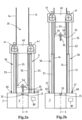
- the figures 1a,b and 2a,b show vertically oriented hydraulic piston-and-cylinder type lift devices 50, each having a cylinder body 51 and a piston rod 52.
- These lift devices 50 each having one of the cylinder and the piston rod thereof fixed in relation to the hull 2 and the other one of the cylinder and the piston rod supports the top sheave assembly 40 thereon so as to be vertically mobile relative to the tower.
- the figures 1a,b and 2a,b show carrier suspension cables 55, each carrier suspension cable having one end 56 thereof secured to the travelling top drive carrier 35.
- the cables 55 each extend over a respective sheave 41 of the top sheave assembly 40 to another end 57 of the carrier suspension cable.
- This other end 57 is connected to an anchor 60 that is fixed in relation to the hull, e.g. embodied as an equalizing anchor as described in US6095501 .
- a hydraulic circuit 80 is connected to the lift devices 50.
- This circuit includes a hydraulic pump, e.g. multiple pumps in parallel, and is configured to lift and lower the travelling top drive carrier 35 by extension and retraction of the lift devices 50.
- the figures 1a , 2a show the lift devices 50 when fully retracted, and the figures 1b , 2b show the lift devices in extended position thereof.
- the lift devices 50 and the hydraulic circuit 80 form also a heave compensation system acting on the carrier suspension cables 55 and configured to provide for heave compensating motion of the travelling top drive carrier 35.
- the lift devices 50 can be operated in passive or active heave compensation mode by suitable operation of the circuit 80, and thereby the assembly 40 is heave compensated, which results in the carrier 35 being heave compensated.
- FIG. 1 With reference to figures 3a,b - 7a,b now an offshore drilling vessel for performing subsea wellbore related activities will be discussed.
- This vessel 1' is equipped with an installation that includes many of the components as discussed above with reference to figures 1a, b and 2a,b. These components have been denoted with the same reference numerals.
- the drilling installation is provided with a vertically mobile working deck 70, which is vertically movable with respect to the tower 10 and to the hull 2 along the firing line 4 within a motion range including a heave compensation motion range.
- the deck 70 is guided by one or more vertical guide rails mounted on the tower and/or the hull, e.g. the same rails 14, 15 that are employed for the carrier 35.
- the slip device 20 is mounted on the working deck 70, e.g. recessed in the deck.
- multiple slip devices are arranged on the working deck, each displaceable between an operative position in the firing line and a remote, parked position.
- the vertically mobile working deck 70 is suspended from working deck suspension cables 75.
- Each of these working deck suspension cables 75 is reeved independent from the lift devices 50, so that vertical position and vertical motion of the working deck 70 are independent of the operation of the lift devices 50.
- each of the cables 75 has an end portion connected to the working deck 70 that is suspended from a departure sheave 76 that is mounted at a fixed height on the tower 10, preferably lower than the motion range of the top sheave assembly 40.
- An integrated heave compensation system is provided that is configured to establish, in operation thereof, a heave compensated motion of the vertically mobile working deck 70 relative to the tower 10 and to the hull 2 within the associated heave compensation motion range and a synchronous heave compensated motion of the travelling top drive carrier 35 in order to obtain synchronous heave compensated motions of the vertically mobile working deck 70 and the travelling top drive carrier 35.
- the heave compensation system is an integrated heave compensation system which comprises a common heave compensation device 90 that acts on both the carrier suspension cables 36 and the working deck suspension cables 75, so that when a load formed by a tubulars string 100 initially suspended from the travelling top drive carrier 35 is transferred to the slip device 20 or vice versa, the load on the common heave compensation device 90 remains substantially the same.
- the common heave compensation device 90 is embodied as one or more hydraulic piston-and-cylinder type compensator devices 91, 92, each having a cylinder body and a piston rod.
- These compensator devices 91, 92 each have one of the cylinder and the piston rod thereof fixed in relation to the hull and the other one of the cylinder and the piston rod supporting a common anchor 95 thereon.
- Each common anchor 95 is connected to an end of the one or more carrier suspension cables 36 and to an end of the one or more working deck suspension cables 75.
- the compensator devices 91, 92 are connected to a hydraulic circuit that includes a pressurized gas buffer.
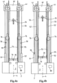
- Figures 4a,b illustrate that the synchronized heave motion compensation of the carrier 35 and of the working deck 70 does not involve the lift devices 50.
- Figure 4a illustrates a situation wherein the compensator devices 91, 92 are fully extended, and in figure 4b these devices are fully retracted, thereby providing a heave compensation motion range for both of the carrier 35 and the working deck (including the slip device 20 thereon) in synchronicity with one another.
- a tubulars string 100 is suspended from slip device 20, e.g. the string 100 passing through a riser into the wellbore.
- slip device 20 e.g. the string 100 passing through a riser into the wellbore.
- a new section 101 e.g. a multi-joint stand of drill pipes, is to be added to the string 100.
- the new section 101 is presented, see figure 5a , by a racker device into alignment with the firing line 4, above the top end of the string 100 held by the slip device 20.
- the carrier 35 has been moved, by operation of the lift devices 50, sufficiently high to place the new section 101 between the working deck 70 and the carrier 35 and top drive 36 and/or elevator carried thereby.
- Figure 5b illustrates that the new section 101 has been connected, e.g. screwed, onto the string 100 at its lower end. This may involve the use of a roughneck device as is known in the art, e.g. mounted on the working deck 70.
- Figure 6a corresponds to figure 5b .
- the carrier 35 is lowered so as to allow the top end of new section 101 to become connected thereto, e.g. to the top drive 36 or to an elevator that is connected to the top drive 36 or that is directly connected to the carrier 35.
- the lowering of the carrier 35 is done by means of suitable operation of hydraulic circuit 80 so as to retract the lift devices 50. This does not have an effect on the support of the working deck 70.
- the slip device 20 can be released from the tubulars string 100 to which the new section 101 has been connected, see the figure 7a .
- this involves transfer of the load of the string 100 from the slip device 20 to the carrier 35, e.g. by means of slightly raising the carrier 35.
- the lift devices 50 are operated to lower the entire string 100, now including new section 101, along the firing line 4. This is done until the slip device 20 can be brought into engagement with an upper end portion of the string 100. The lowering is shown in figure 7b .
- the above cycle is repeated during tripping in until the string 100 has reached the desired depth.
- the integrated heave compensation system is operable, e.g. in a passive heave compensation mode, during the entirety of the cycle described above, with synchronized heave compensation of the carrier 35 and the working deck 70.
- the compensator device 91, 92 are each loaded by both the carrier 35 and the working deck 70, and by any vertical load on the carrier 35 and the working deck 70, the moments of transfer of load between the carrier 35 and the working deck 70 do not have a noticeable effect on the load on the compensator devices 91, 92.
- This is very advantageous, e.g. in view of speed of tripping, e.g. as it avoids the need to adjust settings (e.g. pressure settings) at each time a load transfer is made.
- the vessel is provided with a heave motion compensating pipe racker system comprising at least one racker device that is adapted to move a tubulars section 101, e.g. a drill pipe section, between a tubulars storage rack - that is mounted on the hull or tower vessel and subjected to heave motion - and a position wherein the tubulars section is in said firing line and between the vertically mobile working deck 70 and the travelling top drive carrier 35.
- the racker device comprises multiple racker assemblies, each of said racker assemblies having a motion arm and a gripper member at an end of said motion arm, said gripper member being adapted to grip a tubulars section.
- the racker device further comprises an associated heave motion synchronization system configured to bring, in operation thereof, the racker assemblies in a heave compensation mode with respect to the tower so that a tubular section 101 that has been retrieved from the storage rack by means of the racker assemblies of the racker device is brought into a vertical motion that is synchronous with the heave motion of the mobile working deck and of the slip device provided on said mobile working deck.
- an associated heave motion synchronization system configured to bring, in operation thereof, the racker assemblies in a heave compensation mode with respect to the tower so that a tubular section 101 that has been retrieved from the storage rack by means of the racker assemblies of the racker device is brought into a vertical motion that is synchronous with the heave motion of the mobile working deck and of the slip device provided on said mobile working deck.
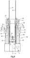
- Figure 8 illustrates an embodiment, wherein the ends of the cables 55, 70 are connected to a fixedly arranged anchor 60' on the hull, or the tower, of the vessel.
- the depicted integrated heave compensation system comprises a first heave compensation sheave assembly, distinct from the top sheave assembly, said first heave compensation sheave assembly comprising one or more sheaves 96 along which the one or more carrier suspension cables 55 pass, and a second heave compensation sheave assembly, comprising one or more sheaves 97 along which the one or more working deck suspension cables 75 pass.
- the first heave compensation sheave assembly and the second heave compensation sheave assembly are mechanically interconnected, e.g. one set of sheaves 96 above another set of sheaves 97, and are connected to the common heave compensation device, here devices 91, 92, so as to allow for synchronous motion thereof.
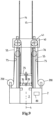
- FIG. 9 illustrates an embodiment, wherein the common heave compensation device is embodied as one or more heave compensated winches 200, e.g. having electronic and/or hydraulic control having heave motion compensation functionality.
- each of said winches 200 is common for the ends of the one or more carrier suspension cables 55 and for the ends of the one or more working deck suspension cables 70 so that each winch is loaded by both the carrier 35 and the deck 70.
- each winch 200 is embodied as a single layer drum type winch, wherein all carrier suspension and working deck suspension cables are wound in a single layer, each onto a corresponding section of the drum.
- one or more operable anchoring devices can be combined with the embodiment of figure 9 , allowing to retain the cables 55, 75 intermediate the winch 200 and the carrier 35 and deck 70.
- the moments of transfer of load between the carrier 35 and the working deck 70 do not have a noticeable effect on the load on the winches 200.
- This is very advantageous, e.g. in view of speed of tripping, e.g. as it avoids the need to adjust settings (e.g. pressure settings) at each time a load transfer is made.
- the carrier 35 can be raised and lowered independently by operation of the one or more pumps in hydraulic circuit 80.
- the scope of protection of the present invention is defined by the appended claims.
Landscapes
- Engineering & Computer Science (AREA)
- Life Sciences & Earth Sciences (AREA)
- Geology (AREA)
- Mining & Mineral Resources (AREA)
- Mechanical Engineering (AREA)
- Physics & Mathematics (AREA)
- Environmental & Geological Engineering (AREA)
- Fluid Mechanics (AREA)
- General Life Sciences & Earth Sciences (AREA)
- Geochemistry & Mineralogy (AREA)
- Earth Drilling (AREA)
Claims (7)
- Offshore-Bohranlage, ausgelegt zum Montieren auf einem Bohrschiff mit einem schwimmenden Rumpf (2), der einen Moonpool (3) umfasst, wobei die Anlage Folgendes umfasst:- einen Bohrturm (10), der dazu ausgelegt ist, auf dem Rumpf an oder in der Nähe des Moonpools positioniert zu werden;- eine Haupthubvorrichtung (30), die Folgendes umfasst:- einen fahrenden Oberantriebsträger (35), angepasst zum Tragen eines Oberantriebs und eines Bohrrohrstrangs (100), der sich entlang einer Firing Line (4) durch den Moonpool erstreckt;- eine obere Seilscheibenanordnung (40), die relativ zu einem erhöhten Teil des Turms vertikal geführt ist und eine oder mehrere Seilscheiben (41) für die Trägeraufhängung umfasst,- eine oder mehrere vertikal ausgerichtete hydraulische Kolben-Zylinder-Hubvorrichtungen (50), die jeweils einen Zylinderkörper (51) und eine Kolbenstange (52) aufweisen, wobei die Hubvorrichtungen jeweils einen Zylinder und eine Kolbenstange aufweisen, die in Bezug auf den Rumpf fixiert sind, und der andere Zylinder und die Kolbenstange die obere Seilscheibenanordnung (40) daran tragen, so dass sie relativ zum Turm vertikal beweglich sind,- ein oder mehrere Trägeraufhängungsseile (55), wobei jedes Trägeraufhängungsseil mit einem Ende (56) an dem fahrenden Oberantriebsträger (35) befestigt ist und sich über eine jeweilige Seilscheibe (41) der oberen Seilscheibenanordnung zu einem anderen Ende (57) des Trägeraufhängungsseils erstreckt, wobei das andere Ende mit einem Anker (60;90;95) verbindbar ist, der in Bezug auf den Rumpf fixierbar ist, oder einer Winde (200) , die in Bezug auf den Rumpf fixierbar ist,- einen Hydraulikkreis (80), der mit der einen oder den mehreren Hubvorrichtungen (50) verbunden ist und eine Hydraulikpumpe umfasst, wobei der Hydraulikkreis dazu ausgelegt ist, den fahrenden Oberantriebsträger (35) durch ein Aus- und Einfahren der einen oder der mehreren Hubvorrichtungen (50) anzuheben und abzusenken,- ein Hubausgleichssystem, das auf das eine oder die mehreren Trägeraufhängungsseile wirkt und dazu ausgelegt ist, eine Hubausgleichsbewegung des fahrenden Oberantriebsträgers bereitzustellen,wobei ein vertikal bewegliches Arbeitsdeck (70) bereitgestellt ist, das in Bezug auf den Turm (10) und den Rumpf (2) entlang der Firing Line innerhalb eines Bewegungsbereichs, der einen Hubkompensationsbewegungsbereich beinhaltet, vertikal beweglich ist,wobei das Arbeitsdeck (70) mit einer Rutschvorrichtung (20) versehen ist, die dazu ausgelegt ist, einen Rohrstrang (100) in der Firing Line aufzuhängen,wobei das vertikal bewegliche Arbeitsdeck (70) an mindestens einem Arbeitsdeck-Aufhängungsseil (75) aufgehängt ist,wobei das mindestens eine Arbeitsdeck-Aufhängungsseil (75) unabhängig von der einen oder den mehreren Hubvorrichtungen (50) aufgehängt wird, so dass die vertikale Position und die vertikale Bewegung des Arbeitsdecks unabhängig von dem Betrieb der einen oder der mehreren Hubvorrichtungen (50) sind,und wobei ein integriertes Hubkompensationssystem bereitgestellt wird, das dazu ausgelegt ist, im Betrieb davon eine Hubkompensationsbewegung des vertikal beweglichen Arbeitsdecks (70) relativ zum Turm und zum Rumpf innerhalb des Hubkompensationsbewegungsbereichs und eine synchrone Hubkompensationsbewegung des fahrenden Verdeckantriebsträgers (35) zu etablieren, um synchrone Hubkompensationsbewegungen des vertikal beweglichen Arbeitsdecks und des fahrenden Oberantriebsträgers zu erhalten,wobei das integrierte Hubkompensationssystem eine gemeinsame Hubkompensationsvorrichtung (90,91,92;200) umfasst, die sowohl auf das eine oder die mehreren Trägeraufhängungsseile (55) als auch auf das eine oder 90 die mehreren Arbeitsdeck-Aufhängungsseile (75) wirkt, so dass, wenn eine Last, die durch einen Rohrstrang (100) gebildet wird, der anfänglich an dem fahrenden Oberantriebsträger (35) aufgehängt ist, auf die Rutschvorrichtung (20) übertragen wird oder umgekehrt, wobei die Last auf die Hubkompensationsvorrichtung (90,91,92;200) im Wesentlichen die gleiche bleibt.
- Offshore-Bohrschiff (1,1') zur Durchführung von Aktivitäten im Zusammenhang mit Unterwasserbohrlöchern, wobei das Schiff Folgendes umfasst:- einen schwimmenden Rumpf (2), der einen Moonpool (3) umfasst;- eine Offshore-Bohranlage nach Anspruch 1, die auf dem schwimmenden Schiffsrumpf installiert ist, wobei der Bohrturm (10) der Bohranlage auf dem Schiffsrumpf an oder in der Nähe des Moonpools des Schiffes positioniert ist; und wobei das andere Ende des einen oder der mehreren Trägeraufhängungsseile (55) mit einem Anker (60;90;95) verbunden ist, der in Bezug auf den Schiffsrumpf fixiert ist, oder mit einer Winde (200), die in Bezug auf den Schiffsrumpf fixiert ist.
- Offshore-Bohrschiff nach Anspruch 2, wobei die gemeinsame Hubkompensationsvorrichtung (90,91,92) direkt mit einem gemeinsamen Anker (95) sowohl für das bzw. die Enden des einen oder der mehreren Trägeraufhängungsseile (55) als auch für das bzw. die Enden des einen oder der mehreren Arbeitsdeck-Aufhängungsseile (75) verbunden ist, wobei die gemeinsame Hubkompensationsvorrichtung zum Beispiel eine oder mehrere hydraulische Kolben-Zylinder-Kompensatorvorrichtungen (91,92) umfasst, die jeweils einen Zylinderkörper und eine Kolbenstange aufweisen, wobei die Kompensatorvorrichtungen jeweils eines aus dem Zylinder und der Kolbenstange davon fixiert in Bezug auf den Rumpf aufweisen, und wobei das andere aus dem Zylinder und der Kolbenstange den gemeinsamen Anker (95) trägt.
- Offshore-Bohrschiff nach Anspruch 2 oder 3, wobei das integrierte Hubkompensationssystem eine erste Hubkompensationsscheibenanordnung umfasst, die sich von der oberen Scheibenanordnung unterscheidet, wobei die erste Hubkompensationsscheibenanordnung eine oder mehrere Scheiben (96) umfasst, entlang denen das eine oder die mehreren Trägeraufhängungskabel (55) verlaufen, und eine zweite Hubkompensationsscheibenanordnung, die eine oder mehrere Scheiben (97) umfasst, entlang denen das eine oder die mehreren Arbeitsdeckaufhängungsseile (75) verlaufen, wobei die erste Hubkompensationsscheibenanordnung und die zweite Hubkompensationsscheibenanordnung mechanisch miteinander verbunden und mit der gemeinsamen Hubkompensationsvorrichtung (91, 92) verbunden sind, um eine synchrone Bewegung davon zu ermöglichen.
- Offshore-Bohrgefäß nach Anspruch 2, wobei die gemeinsame Hubkompensationsvorrichtung eine Hubkompensationswinde (200) umfasst, die für Enden des einen oder der mehreren Trägeraufhängungsseile (55) und für Enden des einen oder der mehreren Arbeitsdeckaufhängungsseile (75) gemeinsam ist, wobei die Winde beispielsweise eine einlagige Trommelwinde ist, wobei Trägeraufhängungsseile und Arbeitsdeckaufhängungsseile (55,75) einlagig jeweils auf einen entsprechenden Abschnitt der Trommel aufgewickelt sind.
- Offshore-Bohrschiff nach einem der Ansprüche 2 bis 5, wobei jedes Arbeitsdeck-Aufhängungskabel (75) einen Endabschnitt aufweist, der mit dem Arbeitsdeck verbunden ist und an einer Abgangsscheibe (76) aufgehängt ist, die in einer festen Höhe am Turm, vorzugsweise niedriger als die obere Scheibenanordnung (40), montiert ist.
- Verfahren zum Durchführen einer unterseeischen bohrlochbezogenen Aktivität, wobei ein Schiff oder eine Anlage nach einem der Ansprüche 1 - 6 verwendet wird, umfassend den Schritt des Einlösens oder Auslösens eines Rohrstrangs.
Applications Claiming Priority (2)
| Application Number | Priority Date | Filing Date | Title |
|---|---|---|---|
| NL2024928A NL2024928B1 (en) | 2020-02-17 | 2020-02-17 | Offshore drilling vessel and installation for performing subsea wellbore related activities. |
| PCT/EP2021/053353 WO2021165143A1 (en) | 2020-02-17 | 2021-02-11 | Offshore drilling vessel and installation for performing subsea wellbore related activities. |
Publications (2)
| Publication Number | Publication Date |
|---|---|
| EP4107359A1 EP4107359A1 (de) | 2022-12-28 |
| EP4107359B1 true EP4107359B1 (de) | 2025-04-02 |
Family
ID=70805157
Family Applications (1)
| Application Number | Title | Priority Date | Filing Date |
|---|---|---|---|
| EP21703735.7A Active EP4107359B1 (de) | 2020-02-17 | 2021-02-11 | Offshore-bohrschiff und anlage zum durchführen von aktivitäten im zusammenhang mit unterwasserbohrlöchern |
Country Status (3)
| Country | Link |
|---|---|
| EP (1) | EP4107359B1 (de) |
| NL (1) | NL2024928B1 (de) |
| WO (1) | WO2021165143A1 (de) |
Families Citing this family (1)
| Publication number | Priority date | Publication date | Assignee | Title |
|---|---|---|---|---|
| NL2033170B1 (en) | 2022-09-28 | 2024-04-05 | Itrec Bv | Offshore drilling vessel and installation for perforing subsea wellbore related activities |
Family Cites Families (6)
| Publication number | Priority date | Publication date | Assignee | Title |
|---|---|---|---|---|
| US6094910A (en) | 1995-12-22 | 2000-08-01 | Maritime Hydraulics As | Apparatus and method for raising and lowering a piston in a piston cylinder arrangement in a derrick |
| NO302772B1 (no) | 1995-12-27 | 1998-04-20 | Maritime Hydraulics As | Strekkompenseringsanordning for heiseanordning for boretårn |
| EP3114025B1 (de) | 2014-03-03 | 2020-05-06 | Itrec B.V. | Offshore-bohrschiff und -verfahren |
| NL2013680B1 (en) * | 2014-10-24 | 2016-10-05 | Itrec Bv | Offshore drilling system, vessel and method. |
| NO346164B1 (en) | 2016-05-06 | 2022-04-04 | Mhwirth As | Hoisting system |
| CN214397139U (zh) * | 2018-02-19 | 2021-10-15 | 伊特里克公司 | 用于执行诸如修井活动、井维护、将物体安装在海底钻井孔上的海底钻井孔相关活动的船 |
-
2020
- 2020-02-17 NL NL2024928A patent/NL2024928B1/en active
-
2021
- 2021-02-11 WO PCT/EP2021/053353 patent/WO2021165143A1/en not_active Ceased
- 2021-02-11 EP EP21703735.7A patent/EP4107359B1/de active Active
Also Published As
| Publication number | Publication date |
|---|---|
| WO2021165143A1 (en) | 2021-08-26 |
| NL2024928B1 (en) | 2021-09-16 |
| EP4107359A1 (de) | 2022-12-28 |
Similar Documents
| Publication | Publication Date | Title |
|---|---|---|
| EP2847417B1 (de) | Offshore-schiff und verfahren für den betrieb eines derartigen offshore-schiffes | |
| US11781384B2 (en) | Drilling installation: handling system, method for independent operations | |
| NL2023277B1 (en) | Retrofitting an existing offshore drilling vessel | |
| EP3710351B1 (de) | Schiff und verfahren zur durchführung von unterirdischen bohrlochbezogenen aktivitäten | |
| WO2016118714A1 (en) | Wellhead-mounted hydraulic workover unit | |
| EP4107359B1 (de) | Offshore-bohrschiff und anlage zum durchführen von aktivitäten im zusammenhang mit unterwasserbohrlöchern | |
| EP3938274B1 (de) | Offshore-system, schiff und verfahren zur durchführung von aktivitäten im zusammenhang mit unterwasserbohrlöchern | |
| EP3755618B1 (de) | Schiff und verfahren zur durchführung von unterirdischen bohrlochbezogenen aktivitäten, z.b. überholungsoperationen, bohrlochinstandhaltung, installation eines objekts auf einem unterirdischen bohrloch | |
| WO2015080584A1 (en) | Motion compensation system, hoisting device, floating marine structure, fixed marine structure | |
| EP3980326B1 (de) | Offshore-bohrsystem, schiff und verfahren | |
| NL2033170B1 (en) | Offshore drilling vessel and installation for perforing subsea wellbore related activities | |
| NL2023412B1 (en) | Offshore drilling system, vessel and method | |
| EP3829967B1 (de) | Halbtauchfähiges schiff | |
| NL2016059B1 (en) | Drilling installation; Handling system, method for independent operations. | |
| WO2010067098A1 (en) | Assembly and method for supporting and deploying an object from a vessel |
Legal Events
| Date | Code | Title | Description |
|---|---|---|---|
| STAA | Information on the status of an ep patent application or granted ep patent |
Free format text: STATUS: UNKNOWN |
|
| STAA | Information on the status of an ep patent application or granted ep patent |
Free format text: STATUS: THE INTERNATIONAL PUBLICATION HAS BEEN MADE |
|
| PUAI | Public reference made under article 153(3) epc to a published international application that has entered the european phase |
Free format text: ORIGINAL CODE: 0009012 |
|
| STAA | Information on the status of an ep patent application or granted ep patent |
Free format text: STATUS: REQUEST FOR EXAMINATION WAS MADE |
|
| 17P | Request for examination filed |
Effective date: 20220902 |
|
| AK | Designated contracting states |
Kind code of ref document: A1 Designated state(s): AL AT BE BG CH CY CZ DE DK EE ES FI FR GB GR HR HU IE IS IT LI LT LU LV MC MK MT NL NO PL PT RO RS SE SI SK SM TR |
|
| DAV | Request for validation of the european patent (deleted) | ||
| DAX | Request for extension of the european patent (deleted) | ||
| GRAP | Despatch of communication of intention to grant a patent |
Free format text: ORIGINAL CODE: EPIDOSNIGR1 |
|
| STAA | Information on the status of an ep patent application or granted ep patent |
Free format text: STATUS: GRANT OF PATENT IS INTENDED |
|
| INTG | Intention to grant announced |
Effective date: 20240506 |
|
| GRAJ | Information related to disapproval of communication of intention to grant by the applicant or resumption of examination proceedings by the epo deleted |
Free format text: ORIGINAL CODE: EPIDOSDIGR1 |
|
| STAA | Information on the status of an ep patent application or granted ep patent |
Free format text: STATUS: REQUEST FOR EXAMINATION WAS MADE |
|
| GRAP | Despatch of communication of intention to grant a patent |
Free format text: ORIGINAL CODE: EPIDOSNIGR1 |
|
| STAA | Information on the status of an ep patent application or granted ep patent |
Free format text: STATUS: GRANT OF PATENT IS INTENDED |
|
| INTC | Intention to grant announced (deleted) | ||
| INTG | Intention to grant announced |
Effective date: 20240909 |
|
| GRAS | Grant fee paid |
Free format text: ORIGINAL CODE: EPIDOSNIGR3 |
|
| GRAA | (expected) grant |
Free format text: ORIGINAL CODE: 0009210 |
|
| STAA | Information on the status of an ep patent application or granted ep patent |
Free format text: STATUS: THE PATENT HAS BEEN GRANTED |
|
| AK | Designated contracting states |
Kind code of ref document: B1 Designated state(s): AL AT BE BG CH CY CZ DE DK EE ES FI FR GB GR HR HU IE IS IT LI LT LU LV MC MK MT NL NO PL PT RO RS SE SI SK SM TR |
|
| REG | Reference to a national code |
Ref country code: GB Ref legal event code: FG4D |
|
| REG | Reference to a national code |
Ref country code: CH Ref legal event code: EP |
|
| REG | Reference to a national code |
Ref country code: IE Ref legal event code: FG4D |
|
| REG | Reference to a national code |
Ref country code: DE Ref legal event code: R096 Ref document number: 602021028482 Country of ref document: DE |
|
| REG | Reference to a national code |
Ref country code: NL Ref legal event code: FP |
|
| REG | Reference to a national code |
Ref country code: AT Ref legal event code: MK05 Ref document number: 1781423 Country of ref document: AT Kind code of ref document: T Effective date: 20250402 |
|
| PG25 | Lapsed in a contracting state [announced via postgrant information from national office to epo] |
Ref country code: FI Free format text: LAPSE BECAUSE OF FAILURE TO SUBMIT A TRANSLATION OF THE DESCRIPTION OR TO PAY THE FEE WITHIN THE PRESCRIBED TIME-LIMIT Effective date: 20250402 Ref country code: ES Free format text: LAPSE BECAUSE OF FAILURE TO SUBMIT A TRANSLATION OF THE DESCRIPTION OR TO PAY THE FEE WITHIN THE PRESCRIBED TIME-LIMIT Effective date: 20250402 Ref country code: PT Free format text: LAPSE BECAUSE OF FAILURE TO SUBMIT A TRANSLATION OF THE DESCRIPTION OR TO PAY THE FEE WITHIN THE PRESCRIBED TIME-LIMIT Effective date: 20250804 |
|
| REG | Reference to a national code |
Ref country code: LT Ref legal event code: MG9D |
|
| PG25 | Lapsed in a contracting state [announced via postgrant information from national office to epo] |
Ref country code: GR Free format text: LAPSE BECAUSE OF FAILURE TO SUBMIT A TRANSLATION OF THE DESCRIPTION OR TO PAY THE FEE WITHIN THE PRESCRIBED TIME-LIMIT Effective date: 20250703 |
|
| PG25 | Lapsed in a contracting state [announced via postgrant information from national office to epo] |
Ref country code: PL Free format text: LAPSE BECAUSE OF FAILURE TO SUBMIT A TRANSLATION OF THE DESCRIPTION OR TO PAY THE FEE WITHIN THE PRESCRIBED TIME-LIMIT Effective date: 20250402 |
|
| PG25 | Lapsed in a contracting state [announced via postgrant information from national office to epo] |
Ref country code: BG Free format text: LAPSE BECAUSE OF FAILURE TO SUBMIT A TRANSLATION OF THE DESCRIPTION OR TO PAY THE FEE WITHIN THE PRESCRIBED TIME-LIMIT Effective date: 20250402 |
|
| PG25 | Lapsed in a contracting state [announced via postgrant information from national office to epo] |
Ref country code: HR Free format text: LAPSE BECAUSE OF FAILURE TO SUBMIT A TRANSLATION OF THE DESCRIPTION OR TO PAY THE FEE WITHIN THE PRESCRIBED TIME-LIMIT Effective date: 20250402 |
|
| PG25 | Lapsed in a contracting state [announced via postgrant information from national office to epo] |
Ref country code: AT Free format text: LAPSE BECAUSE OF FAILURE TO SUBMIT A TRANSLATION OF THE DESCRIPTION OR TO PAY THE FEE WITHIN THE PRESCRIBED TIME-LIMIT Effective date: 20250402 |
|
| PG25 | Lapsed in a contracting state [announced via postgrant information from national office to epo] |
Ref country code: RS Free format text: LAPSE BECAUSE OF FAILURE TO SUBMIT A TRANSLATION OF THE DESCRIPTION OR TO PAY THE FEE WITHIN THE PRESCRIBED TIME-LIMIT Effective date: 20250702 |
|
| PG25 | Lapsed in a contracting state [announced via postgrant information from national office to epo] |
Ref country code: IS Free format text: LAPSE BECAUSE OF FAILURE TO SUBMIT A TRANSLATION OF THE DESCRIPTION OR TO PAY THE FEE WITHIN THE PRESCRIBED TIME-LIMIT Effective date: 20250802 |
|
| PG25 | Lapsed in a contracting state [announced via postgrant information from national office to epo] |
Ref country code: LV Free format text: LAPSE BECAUSE OF FAILURE TO SUBMIT A TRANSLATION OF THE DESCRIPTION OR TO PAY THE FEE WITHIN THE PRESCRIBED TIME-LIMIT Effective date: 20250402 |