EP4107106B1 - Elevator system - Google Patents
Elevator system Download PDFInfo
- Publication number
- EP4107106B1 EP4107106B1 EP21706257.9A EP21706257A EP4107106B1 EP 4107106 B1 EP4107106 B1 EP 4107106B1 EP 21706257 A EP21706257 A EP 21706257A EP 4107106 B1 EP4107106 B1 EP 4107106B1
- Authority
- EP
- European Patent Office
- Prior art keywords
- elevator
- cabin
- support
- car
- vertical
- Prior art date
- Legal status (The legal status is an assumption and is not a legal conclusion. Google has not performed a legal analysis and makes no representation as to the accuracy of the status listed.)
- Active
Links
Images


Classifications
-
- B—PERFORMING OPERATIONS; TRANSPORTING
- B66—HOISTING; LIFTING; HAULING
- B66B—ELEVATORS; ESCALATORS OR MOVING WALKWAYS
- B66B9/00—Kinds or types of lifts in, or associated with, buildings or other structures
- B66B9/003—Kinds or types of lifts in, or associated with, buildings or other structures for lateral transfer of car or frame, e.g. between vertical hoistways or to/from a parking position
-
- B—PERFORMING OPERATIONS; TRANSPORTING
- B66—HOISTING; LIFTING; HAULING
- B66B—ELEVATORS; ESCALATORS OR MOVING WALKWAYS
- B66B11/00—Main component parts of lifts in, or associated with, buildings or other structures
- B66B11/02—Cages, i.e. cars
- B66B11/0206—Car frames
-
- B—PERFORMING OPERATIONS; TRANSPORTING
- B66—HOISTING; LIFTING; HAULING
- B66B—ELEVATORS; ESCALATORS OR MOVING WALKWAYS
- B66B11/00—Main component parts of lifts in, or associated with, buildings or other structures
- B66B11/02—Cages, i.e. cars
- B66B11/026—Attenuation system for shocks, vibrations, imbalance, e.g. passengers on the same side
- B66B11/0293—Suspension locking or inhibiting means to avoid movement when car is stopped at a floor
-
- B—PERFORMING OPERATIONS; TRANSPORTING
- B66—HOISTING; LIFTING; HAULING
- B66B—ELEVATORS; ESCALATORS OR MOVING WALKWAYS
- B66B17/00—Hoistway equipment
- B66B17/34—Safe lift clips; Keps
Definitions
- the invention refers to an elevator system, in particular to a ropeless elevator system comprising one or multiple elevator cabins.
- a car arrangement for an elevator system is disclosed in WO 2018/153650 .
- the car arrangement comprises a car support with at least one horizontal leg and at least one vertical leg, the elevator car resting on the at least one horizontal leg and the horizontal leg being at least indirectly connected to a bearing via the vertical leg.
- the weight of the elevator car including the payloads, is largely passed through the car floor as compressive forces.
- Such an arrangement however requires a substantial amount of space about the exterior of the elevator car within the elevator shaft and therefore restricts the size of the elevator car that can be used.
- WO 2018/046406 A1 which may be considered as closest prior art, shows an elevator having a cabin.
- the cabin is supported on a carrier in a forklift manner.
- a level of the cabin floor can be lifted or lowered to the cabin floor level matches to a floor level of a floor level in the building. That is required due to load changes during unloading and loading at a stop of the cabin at a floor.
- Due to the forklift like structure the amount of space required below the elevator cabin floor is high, which is of minor advantage if the elevator cabin is traveling in a horizontal shaft.
- the space below the cabin a may be limited in a horizontal shaft.
- CN 205 312 834 U discloses a ring rail shaped elevator including: a car, drive arrangement, bearing, suspension and a circulating track.
- the car is suspended on one side.
- the suspension includes an anti-rolling device, horizontal bumper shock absorber, vertical bumper shock absorber, high adjusting device and counter weight device.
- the drive arrangement is located facing the circulating track.
- CN 205 312 834 U discloses an elevator system according to the preamble of claim 1.
- CN 108 821 063 A discloses a modular two-dimensional elevator group comprising a plurality of cars capable of switching between a horizontal hoistway and a vertical hoistway.
- the car being provided with a multi-composite safety brake system.
- the car is comprised of a linear power pack drive that turns the car in a horizontal or vertical direction through a steering knot.
- JP H04 191280 A discloses an elevator driving device for moving an elevator car movably disposed in an elevator car passage.
- the device having an elevating passage provided therein and a transverse passage communicating the elevating passage
- the elevator driving device comprising: an elevator cage projecting from the elevator car, a movable element rotatably mounted to the elevator car, a tubular shaped member disposed along the moving direction of the elevator car and surrounding the outer periphery of the movable element so as to be movable in the axial direction and guiding the elevator car along the axial direction
- a stator arranged along the axial direction of the tubular inner circumferential portion of the guide means and moving the elevator car through the mover by successively exciting the elevator car along the axial direction.
- the invention relates to a, in particular ropeless, elevator system having at least one elevator shaft and at least one elevator car.
- the elevator system can comprise a plurality of said elevator cars.
- the elevator car comprises:
- the sledge is a mechanism that connects to both
- the elevator car is adapted to switch between a first elevator shaft and at least one further elevator shaft, wherein the car can travel in both directions, in particular in upwards and downwards direction in each vertical shaft and or sidewards in a horizontal shaft.
- the elevator support is comprised in a suspension system, preferably a rucksack suspension system, such that it is positioned in parallel with a vertical wall in particular a single side of the elevator cabin, preferably the rear side of the elevator cabin.
- the rear side may be opposite the front side of the elevator cabin where passengers enter and exit.
- This type of elevator support is preferably as streamlined as possible with the rear wall of the elevator cabin, thus space can be saved or even redistributed within the elevator shaft. This can accommodate for example:
- the elevator cabin comprises a reinforced rear wall and a reinforced floor structure. This advantageously provides for the connection of the elevator support to the elevator cabin.
- the elevator support comprises a plurality of panels which intersect at a point Pi, each panel preferably comprising a plurality of connection means.
- the plurality of connection means are adapted to connect to one or both of:
- the elevator support is adapted to extend at least partially across the height of the elevator cabin, more preferably, extend across at least two thirds of the height of the elevator cabin. This advantageously provides support to a larger surface area of the cabin thereby increasing safety.
- the elevator support is adapted to extend substantially across the total height of the elevator cabin. This advantageously provides support to a larger surface area of the cabin thereby increasing safety.
- the elevator support further comprises a bearing housing located around the point of intersection Pi wherein the bearing housing comprises a plurality of working elements adapted to facilitate the travelling direction of the elevator car along one or more vertically, or vertically and/or horizontally extending rail comprised within the elevator shaft.
- the elevator system comprises one or more auxiliary mechanism, this advantageously provides a means that allows the cabin to move relative to the sledge and the shaft in order to compensate for e.g.;
- the one or more auxiliary mechanism is selected from the group comprising:
- One or more auxiliary mechanism can also advantageously function as a safety mechanism whilst simultaneously improving passenger comfort.
- a levelling system can help ensure that the sill of the elevator cabin is at the same level as the sill of the landing.
- a damping system can help absorb any unpleasant effects of unexpected movements of the cabin thereby preventing discomfort to passengers.
- a locking system can for example function as a supporting device to the elevator cabin when it stops at each landing area, thereby helping to mitigate any risk that the drive motor of the elevator car overheats.
- a brake system for example can facilitate weight distribution and help relieve the weight on the car for a given time period.
- the one or more auxiliary mechanism preferably the levelling system comprises a camshaft system.
- the one or more auxiliary mechanism preferably the damping system, and/or the locking system and/or the brake system comprises a linear actuator arrangement.
- the one or more auxiliary mechanism is comprised within one or more of:
- connection means comprises
- the elevator support is comprised of a light-weight composite material wherein the composite material comprises at least one from the group including:
- the elevator support according to any embodiment of the invention is preferably made out of a light-weight resilient material, for example, aluminum casting and extrusion profile. Therefore, the overall weight of the elevator cabin is reduced, improving its performance and operational lifetime.
- center of gravity of the cabin is located horizontally offset from the support.
- an actuator arrangement is provided, adapted to change the orientation of the, in particular cantilevered supported, cabin relative to the support.
- the actuator arrangement comprises a tilting actuator adapted to change the orientation of the cabin relative to the support by tilting the cabin relative to the support in particular along a horizontal axis.
- a lifting actuator is provided adapted to change the orientation of the cabin relative to the support thereby lifting or lowering the cabin relative to the support.
- actuator arrangement and/or the lifting actuator and/or the tilting actuator is part of the cabin.
- the actuator arrangement and/or the lifting actuator and/or the tilting actuator are located stationary at the elevator shaft and are adapted to interact selectively with an individual cabin when the cabin is located the sphere of influence of the cabin if the actuator arrangement and/or the lifting actuator and/or the tilting actuator.
- the cabin is connected to the support, in particular at the upper area and the lower area at a lower area of the vertical wall by connecting means wherein the connecting means allow a vertical adjustment the position of the cabin relative to the support.
- the invention also relates to the use of an elevator system according to any of the preceding embodiments in a high rise building.
- Fig. 12 shows parts of an inventive elevator system.
- Several, here exemplarily two, vertical travel tracks 2VL, 2VR are aligned in a first direction z, along which the cars 5 can be moved between different floors.
- horizontal travel tracks 2H are arranged in a second direction y, along which the cars 1 are each movable within one floor.
- the horizontal travel track 2H connects the two vertical travel tracks 2VL, 2VR with each other.
- the horizontal track 2H also serves to transfer the cars 1 between the two vertical tracks 2VL, 2VR between the two vertical tracks 2VL, 2VR.
- Additional horizontal travel tracks may be provided in the elevator system, which connect the two vertical travel tracks with each other. Further vertical tracks may also be provided, not shown, may be provided.
- Rails 22V, 22H, 22B are provided along the tracks to guide the cars 1.
- the cars 1 have guide rollers for this purpose that are not shown.
- the transfer unit comprises a movable rail 22B.
- the elevator car has a sledge 11 with rollers 13, wherein the rollers 13 provides guidance of the sledge at the rails 22.
- the sledge 11 has a support bearing 12, to which a support 10 of the car 1 is attached in a rotatably manner.
- the elevator 1 car has a cabin 100 for accommodation of passengers.
- the support 10 connects the cabin 100 with the sledge of the car 1.
- the orientation of the sledge 11 can change from a vertical orientation to a horizontal orientation.
- the orientation of the cabin stays always constant.
- the sledge 11 is shown in figure 12 without an attached support and cabin.
- An elevator having such a structure is in principle disclosed in DE WO 2015/144781 A1 , DE 10 2016 211 997A1 and DE 10 2015 218 025 A1 .
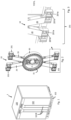
- an elevator cabin 100 is shown having a reinforced vertical wall 101 (with reinforcements 101R) and a reinforced floor structure 102.
- the vertical wall is a rear wall.
- the cabin 100 is adapted such that an elevator support 10 (not shown) according to an embodiment of the invention can be attached thereto.
- the elevator support 10 is described in further detail in figures 2 to 8 .
- the support 10 is connected to the cabin 100 at a lower area 101L of the vertical wall 101 and at an upper area 101U of the vertical wall.
- the connection has not to be immediate between the wall and the support itself. Compared the solution of the prior art less space is required below the elevator floor.
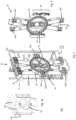
- Fig. 2 shows an elevator support 10 according to a first embodiment of the invention.
- the elevator support 10 comprises two elongated panels 20 which intersect at their respective centers at point P i to form in particular an "X" shape.
- a bearing housing 30 Surrounding the point of intersection P i is a bearing housing 30 which comprises a plurality of working elements 31 for example a locking device between a sledge (not shown), and the support 10.
- the plurality of working elements 31 are adapted to facilitate the travelling direction of the elevator car 1 along the one or more vertically extending rail.
- These working elements 31 also provide for example a rotative function that enables an elevator cabin e.g., the elevator cabin 100 to switch between elevator shafts and thereby travel in both vertical and horizontal directions.
- the bearing housing 30 can also optionally act as a point of connection between the elevator cabin 100 and the support 10, however it is not shown in this particular example. Further information regarding how an elevator cabin moves between elevator shafts can be found in the applicant's patent EP 3122680 B1 .
- the support 10 comprises at the end of each panel 20 a connection means 201, this is shown more clearly in fig. 3 .
- the elevator cabin 100 is connected to the support 10 at each connection means 201.
- the connection means 201 is adapted to be attached to the reinforced wall 101 and/or the reinforced floor structure 102 of the elevator cabin 100 in each case in the lower area 101L of the rear wall 101. This is shown more clearly in figure 6 .
- connection means 201 comprise a first connecting elements 201a and second connecting elements 201b.
- first connecting element 201a include one or more of screws, nuts and bolts however any suitable connecting element.
- the first connecting element 201a is attached to the cabin 100
- the second connecting element201b is attached to the support 10 and/or the panel 20 of the support
- the connecting elements allow a vertical relative movement of the second connecting element 201b relative to the first connecting element 201a, so that the position vertical orientation between the cabin (and consequently to the cabin floor) relative to the support can be adjusted.
- the connection means 201 can be a linear bearing which supports vertical movement. So as an example, a connecting element 201a, b can be a vertical oriented bolt, which is at least partially surrounded by the respective other connecting element.
- the cabin 100 is held relative to the support in a cantilever like manner, resulting horizontal in heavy horizontal forces Fh.
- a main function of the connecting means 201 in the upper and lower 101U, 101L area is to transmit at least theses horizontal forces Fh from the cabin to the support 10.
- Cantilevered means, that the support is not located below the center of gravity of the cabin, so that the cabin weight cannot be transferred by merely vertically forces, but also by bending stress.
- the elevator support 10 can optionally comprise one or more auxiliary mechanism to facilitate and improve the mobility quality of the elevator cabin 100.
- a damping system can be introduced, wherein said system comprises a spring, or a pneumatic or hydraulic mechanism.
- a levelling system could also be introduced whereby the elevator cabin 100 can be rotated or tilted any number of degrees to ensure that the sill of the elevator cabin and the sill at the landing side are at the same level. This is described in further detail in figs. 4, 5 , 7 and 8 .
- Fig. 4 shows a support 10 according to a second embodiment of the invention.
- the support 10 comprises two elongated panels 20 which intersect at their respective centers at point P i to form an "X" shape.
- a bearing housing 30 Surrounding the point of intersection P i is a bearing housing 30 which comprises a plurality of working elements 31 for example a locking device between a sledge (not shown) and the support.
- the plurality of working elements 31 are adapted to facilitate the travelling direction of the elevator car 1 along the one or more vertically extending rail.
- These working elements 31 also provide for example a rotative function that enables an elevator cabin e.g., the elevator cabin 100 to switch between elevator shafts and thereby travel in both vertical and horizontal directions.
- connection means 201 is comprised at the bottom end of each of the intersecting panels 20.
- This connection means 201 provides a rotation axle 2021 and is preferably comprised of a bolt or a load measuring bolt or other similar means.
- the bearing housing 30 comprises a connection means 203.
- the connection means 203 provides a middle fixation means 2031 and is preferably comprised of a bolt or other similar means and curved long hole which helps to enable rotation.
- connection means 202 is adapted to comprise an auxiliary mechanism 40, wherein said mechanism 40 is a camshaft system 40.
- the camshaft system 40 functions as a levelling system, whereby the elevator cabin 100 can be tilted any number of degrees to ensure that the sill on the cabin side is at the same level as the sill of the landing side.
- the camshaft system 40 comprises a motor 41 for camshaft rotation.
- the camshaft system 40 is secured to the reinforced rear wall 101 of the elevator cabin 100 allowing for the cabin 100 to be tilted as shown by the arrow A in fig. 4a .
- Fig. 5 shows an elevator support 10 according to a third embodiment of the invention.
- the support 10 comprises two elongated panels 20 which intersect at their respective centers at point P i to form an "X" shape.
- a bearing housing 30 Surrounding the point of intersection P i is a bearing housing 30 which comprises a plurality of working elements 31 for example a locking device between a sledge (not shown) and the support 10.
- the plurality of working elements 31 are adapted to facilitate the travelling direction of the elevator car 1 along the one or more vertically extending rail.
- These working elements 31 also provide for example a rotative function which enables an elevator cabin e.g., the elevator cabin 100 to switch between elevator shafts and thereby travel in both vertical and horizontal directions.
- the support 10 comprises a connection means 204 at each end of the intersecting panels 20, wherein said connection means 204 is preferably comprised of a bolt or a load measuring bolt or other similar means.
- the connection means 204 is connected to the reinforced rear wall 101 of the elevator cabin 100.
- An auxiliary mechanism 50 is provided which can be optionally connected to the elevator cabin 100 at the reinforced rear wall 101.
- the auxiliary mechanism 50 is comprised of a linear actuator arrangement e.g., a linear motor, hydraulic/pneumatic cylinder.
- This linear actuator arrangement 50 functions as a damping system to aid in vibration absorption.
- the linear actuator arrangement 50 can also facilitate cabin levelling.
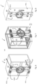
- Fig. 6, fig. 7 and fig. 8 show a schematic representation of how the support10 according to each embodiment of the invention looks when attached to an elevator cabin 100, at the reinforced rear wall 101 and reinforced floor structure 102.
- fig. 7 the structural outline of a cabin 100 is shown.
- a rubber bushing can optionally be added to aid in vibration absorption.
- Figs. 9a to 9c show a side view schematic representation of an auxiliary mechanism 60 which is located in the elevator shaft 2.
- the auxiliary mechanism is a locking system 60 which also facilitates in the re-leveling of the elevator cabin 100.
- the locking system 60 offers the opportunity to transfer the weight and electrical power necessary for re-leveling from the cabin 100 side to the shaft 2 side. At the shaft 2 side, considerations such as weight and electrical power are less of an issue.
- the cabin 100 is mounted to a support 10 according to any embodiment of the invention (shown more clearly in fig. 11 ).
- the locking system 60 is attached to the shaft 2, in particular to the shaft wall. In fig. 9a , the locking system 60 is at rest. With reference to fig. 10a, fig.
- the locking system 60 comprises a base body 61 which is attached to the shaft wall of shaft 2.
- An extendable arm 611 is comprised within the base body 61 which is extended when the locking system 60 is in operation (see figs. 9b and 9c ).
- the base body 61 comprises a piston assembly 62 comprising a set of extendable pistons 621 which also extend when the locking system 60 is in operation (see figs. 9b and 9c ).
- the piston assembly 62 is rotatably connected to the base body 61 at point connection 622.
- the extendable arm 611 and the extendable pistons 621 converge at a ledge 63.
- the ledge 63 is rotatable about connection point 631 which connects the extendable pistons 621 with the ledge 63.
- connection point 631 which connects the extendable pistons 621 with the ledge 63.
- Fig. 10b shows an alternative locking system 60 wherein the base body 61 comprises a set of extendable arms 611 which converge to a ledge 63.
- This alternative system 60 operates in the same way as the system 60 described previously.
- Fig. 11 shows a schematic representation of an elevator car 1 comprising an elevator cabin 100 and an elevator support 10 in an elevator shaft (not shown) having a locking system 60.
- the locking system 60 is in its fully extended position with ledge 63 contacting the reinforced floor 102 of the elevator cabin 100 at both rear corners.
Landscapes
- Engineering & Computer Science (AREA)
- Structural Engineering (AREA)
- Civil Engineering (AREA)
- Mechanical Engineering (AREA)
- Automation & Control Theory (AREA)
- Cage And Drive Apparatuses For Elevators (AREA)
- Lift-Guide Devices, And Elevator Ropes And Cables (AREA)
Description
- The invention refers to an elevator system, in particular to a ropeless elevator system comprising one or multiple elevator cabins.
- A car arrangement for an elevator system is disclosed in
WO 2018/153650 . The car arrangement comprises a car support with at least one horizontal leg and at least one vertical leg, the elevator car resting on the at least one horizontal leg and the horizontal leg being at least indirectly connected to a bearing via the vertical leg. When the elevator car rests on the car carrier, the weight of the elevator car, including the payloads, is largely passed through the car floor as compressive forces. Such an arrangement however requires a substantial amount of space about the exterior of the elevator car within the elevator shaft and therefore restricts the size of the elevator car that can be used. -
WO 2018/046406 A1 , which may be considered as closest prior art, shows an elevator having a cabin. The cabin is supported on a carrier in a forklift manner. A level of the cabin floor can be lifted or lowered to the cabin floor level matches to a floor level of a floor level in the building. That is required due to load changes during unloading and loading at a stop of the cabin at a floor. Due to the forklift like structure the amount of space required below the elevator cabin floor is high, which is of minor advantage if the elevator cabin is traveling in a horizontal shaft. - In contrast to a vertical shaft the space below the cabin a may be limited in a horizontal shaft.
-
CN 205 312 834 U discloses a ring rail shaped elevator including: a car, drive arrangement, bearing, suspension and a circulating track. The car is suspended on one side. The suspension includes an anti-rolling device, horizontal bumper shock absorber, vertical bumper shock absorber, high adjusting device and counter weight device. The drive arrangement is located facing the circulating track.CN 205 312 834 U discloses an elevator system according to the preamble ofclaim 1. -
CN 108 821 063 A discloses a modular two-dimensional elevator group comprising a plurality of cars capable of switching between a horizontal hoistway and a vertical hoistway. The car being provided with a multi-composite safety brake system. The car is comprised of a linear power pack drive that turns the car in a horizontal or vertical direction through a steering knot. -
JP H04 191280 A - It is an object of the invention to provide an elevator car in particular wherein the car
- is adapted to allow for a more efficient use of space within an in particular horizontal elevator shaft and
- has an improved safety function.
- This object is solved by the subject of the main claims; embodiments are subject of the subclaims and the description.
- The invention relates to a, in particular ropeless, elevator system having at least one elevator shaft and at least one elevator car. Preferably the elevator system can comprise a plurality of said elevator cars. The elevator car comprises:
- an elevator cabin adapted to transport passengers between floors of a building;
- an elevator support adapted to support the weight of the elevator cabin.
- at least one further mechanism wherein the at least one further mechanism is hereinafter referred to as a sledge. The elevator support is adapted to connect to both the elevator cabin and the sledge.
- The sledge is a mechanism that connects to both
- the elevator support and
- one or more vertically, or vertically and/or horizontally extending rail comprised in an elevator shaft such that the elevator cabin is moveable along said rails. As well as guiding the cabin along the rails, the sledge can also advantageously be adapted to comprise braking elements and one or more auxiliary mechanism, e.g., a damping system. For more information on the sledge, the German
patent application DE 10 2019 200 235.8 is available. - In an embodiment of the invention, the elevator car is adapted to switch between a first elevator shaft and at least one further elevator shaft, wherein the car can travel in both directions, in particular in upwards and downwards direction in each vertical shaft and or sidewards in a horizontal shaft.
- According to the invention, the elevator support is comprised in a suspension system, preferably a rucksack suspension system, such that it is positioned in parallel with a vertical wall in particular a single side of the elevator cabin, preferably the rear side of the elevator cabin. The rear side may be opposite the front side of the elevator cabin where passengers enter and exit. This type of elevator support is preferably as streamlined as possible with the rear wall of the elevator cabin, thus space can be saved or even redistributed within the elevator shaft. This can accommodate for example:
- larger cabins to be used, thereby increasing passenger capacity and reducing passenger waiting times, thus improving passenger comfort and satisfaction;
- a reduction in the amount of space required in an elevator shaft, thereby leaving more usable floor space in the building itself, which appeals to owners and customers alike. The Integration of the cabin and the elevator support as one system according to the invention also advantageously provides a weight reduction without compromising safety and increases the stiffness.
- In an embodiment of the invention, the elevator cabin comprises a reinforced rear wall and a reinforced floor structure. This advantageously provides for the connection of the elevator support to the elevator cabin.
- In an embodiment of the invention, the elevator support comprises a plurality of panels which intersect at a point Pi, each panel preferably comprising a plurality of connection means.
- In an embodiment of the invention, the plurality of connection means are adapted to connect to one or both of:
- the reinforced rear wall of the elevator cabin;
- the reinforced floor structure of the elevator cabin. This advantageously ensures that the elevator support is positioned in parallel with a single side of the elevator cabin. This type of elevator support is preferably as streamlined as possible with the rear wall of the elevator cabin, thus space can be saved or even redistributed within the elevator shaft.
- In an embodiment of the invention, the elevator support, is adapted to extend at least partially across the height of the elevator cabin, more preferably, extend across at least two thirds of the height of the elevator cabin. This advantageously provides support to a larger surface area of the cabin thereby increasing safety.
- In an embodiment of the invention, the elevator support is adapted to extend substantially across the total height of the elevator cabin. This advantageously provides support to a larger surface area of the cabin thereby increasing safety.
- In an embodiment of the invention, the elevator support further comprises a bearing housing located around the point of intersection Pi wherein the bearing housing comprises a plurality of working elements adapted to facilitate the travelling direction of the elevator car along one or more vertically, or vertically and/or horizontally extending rail comprised within the elevator shaft.
- In an embodiment of the invention, the elevator system comprises one or more auxiliary mechanism, this advantageously provides a means that allows the cabin to move relative to the sledge and the shaft in order to compensate for e.g.;
- any construction tolerances;
- installation inaccuracies;
- movement of the building due to temperature or wind;
- subsidence;
- natural environmental factors, e.g. vegetation growth, proximity to a flood plane;
- man-made environmental changes, e.g. other buildings being constructed in close proximity, construction or maintenance on underground travel networks. It is advantageous to have an elevator system that is adaptable and can continue to function should such events occur.
- In an embodiment of the invention, the one or more auxiliary mechanism is selected from the group comprising:
- a levelling system - preferably to aid in the control of the positioning of a sill of the elevator cabin with respect to a sill of a landing area;
- a damping system;
- a locking system;
- a brake system.
- It is advantageous to have one or more auxiliary mechanism because it facilitates and improves the mobility quality of the elevator system. One or more auxiliary mechanism can also advantageously function as a safety mechanism whilst simultaneously improving passenger comfort.
- A levelling system can help ensure that the sill of the elevator cabin is at the same level as the sill of the landing.
- A damping system can help absorb any unpleasant effects of unexpected movements of the cabin thereby preventing discomfort to passengers.
- A locking system can for example function as a supporting device to the elevator cabin when it stops at each landing area, thereby helping to mitigate any risk that the drive motor of the elevator car overheats.
- A brake system for example can facilitate weight distribution and help relieve the weight on the car for a given time period.
- Any one or combination of the above-described auxiliary mechanisms advantageously improves passenger comfort as well as the operational lifetime of the elevator system. In an embodiment of the invention, the one or more auxiliary mechanism, preferably the levelling system comprises a camshaft system.
- In an embodiment of the invention, the one or more auxiliary mechanism, preferably the damping system, and/or the locking system and/or the brake system comprises a linear actuator arrangement.
- In an embodiment of the invention, the one or more auxiliary mechanism is comprised within one or more of:
- the elevator support, preferably, at the connection means;
- the bearing housing;
- the elevator cabin, preferably, at the reinforced rear wall;
- the reinforced floor;
- the elevator shaft.
- In an embodiment of the invention, the connection means comprises
- a bolt, and/or
- a load bearing bolt; and/or
- one or more auxiliary mechanism;
- a combination of any of the above.
- In an embodiment of the invention, the elevator support is comprised of a light-weight composite material wherein the composite material comprises at least one from the group including:
- aluminum;
- titanium;
- nickel;
- tungsten;
- carbon;
- magnesium;
- one or more thermosetting or thermoplastic polymer;
- an alloy comprising one or more of the above.
- In comparison with a traditional bucket that supports an elevator cabin, the elevator support according to any embodiment of the invention is preferably made out of a light-weight resilient material, for example, aluminum casting and extrusion profile. Therefore, the overall weight of the elevator cabin is reduced, improving its performance and operational lifetime.
- In an embodiment the center of gravity of the cabin is located horizontally offset from the support.
- In an embodiment an actuator arrangement is provided, adapted to change the orientation of the, in particular cantilevered supported, cabin relative to the support.
- In an embodiment the actuator arrangement comprises a tilting actuator adapted to change the orientation of the cabin relative to the support by tilting the cabin relative to the support in particular along a horizontal axis.
- In an embodiment a lifting actuator is provided adapted to change the orientation of the cabin relative to the support thereby lifting or lowering the cabin relative to the support.
- In an embodiment the actuator arrangement and/or the lifting actuator and/or the tilting actuator is part of the cabin.
- In an embodiment the actuator arrangement and/or the lifting actuator and/or the tilting actuator are located stationary at the elevator shaft and are adapted to interact selectively with an individual cabin when the cabin is located the sphere of influence of the cabin if the actuator arrangement and/or the lifting actuator and/or the tilting actuator.
- According to the invention, the cabin is connected to the support, in particular at the upper area and the lower area at a lower area of the vertical wall by connecting means wherein the connecting means allow a vertical adjustment the position of the cabin relative to the support.
- The invention also relates to the use of an elevator system according to any of the preceding embodiments in a high rise building.
- The invention is described in more detail with the help of the figures wherein:
- Fig. 1
- shows a typical elevator cabin having a reinforced rear wall and floor structure;
- Fig. 2
- shows an elevator cabin support according to a first embodiment of the invention;
- Fig. 3
- shows an exploded view of a section of the elevator cabin support shown in
fig. 2 ; - Fig. 4
- shows an elevator cabin support according to a second embodiment of the invention;
- Fig. 4a
- shows an exploded view of a section of the elevator cabin support shown in
Fig. 4 ; - Fig. 4
- shows an elevator cabin comprising an elevator cabin support according to a third embodiment of the invention;
- Figs. 5-8
- show an elevator cabin comprising an elevator cabin support according to a first, second and third embodiment of the invention respectively;
- Figs. 9a to 9c
- show a schematic representation of an elevator cabin and an auxiliary mechanism;
- Figs. 10a, 10b
- show a schematic representation of an auxiliary mechanism;
- Fig. 11
- shows a schematic representation of an elevator car in an elevator shaft comprising an auxiliary mechanism
- Fig. 12
- the overall structure of an inventive elevator system.
-
Fig. 12 shows parts of an inventive elevator system. Several, here exemplarily two, vertical travel tracks 2VL, 2VR are aligned in a first direction z, along which the cars 5 can be moved between different floors. Between the two vertical travel tracks 2VL, 2VR,horizontal travel tracks 2H are arranged in a second direction y, along which thecars 1 are each movable within one floor. Furthermore, thehorizontal travel track 2H connects the two vertical travel tracks 2VL, 2VR with each other. Thus, thehorizontal track 2H also serves to transfer thecars 1 between the two vertical tracks 2VL, 2VR between the two vertical tracks 2VL, 2VR. Additional horizontal travel tracks may be provided in the elevator system, which connect the two vertical travel tracks with each other. Further vertical tracks may also be provided, not shown, may be provided. -
Rails cars 1. Thecars 1 have guide rollers for this purpose that are not shown. Along transfer units thecar 1 can transfer from one track to another track. In this embodiment the transfer unit comprises amovable rail 22B. - The elevator car has a
sledge 11 withrollers 13, wherein therollers 13 provides guidance of the sledge at the rails 22. Thesledge 11 has asupport bearing 12, to which asupport 10 of thecar 1 is attached in a rotatably manner. Theelevator 1 car has acabin 100 for accommodation of passengers. Thesupport 10 connects thecabin 100 with the sledge of thecar 1. During travel the orientation of thesledge 11 can change from a vertical orientation to a horizontal orientation. The orientation of the cabin stays always constant. For illustration purposes thesledge 11 is shown infigure 12 without an attached support and cabin. - An elevator having such a structure is in principle disclosed in DE
WO 2015/144781 A1 ,DE 10 2016 211 997A1DE 10 2015 218 025 A1 - In
fig. 1 anelevator cabin 100 is shown having a reinforced vertical wall 101 (withreinforcements 101R) and a reinforcedfloor structure 102. Here the vertical wall is a rear wall. Thecabin 100 is adapted such that an elevator support 10 (not shown) according to an embodiment of the invention can be attached thereto. Theelevator support 10 is described in further detail infigures 2 to 8 . - The
support 10 is connected to thecabin 100 at alower area 101L of thevertical wall 101 and at anupper area 101U of the vertical wall. In particular the connection has not to be immediate between the wall and the support itself. Compared the solution of the prior art less space is required below the elevator floor. -
Fig. 2 shows anelevator support 10 according to a first embodiment of the invention. Theelevator support 10 comprises twoelongated panels 20 which intersect at their respective centers at point Pi to form in particular an "X" shape. Surrounding the point of intersection Pi is a bearinghousing 30 which comprises a plurality of workingelements 31 for example a locking device between a sledge (not shown), and thesupport 10. The plurality of workingelements 31 are adapted to facilitate the travelling direction of theelevator car 1 along the one or more vertically extending rail. These workingelements 31 also provide for example a rotative function that enables an elevator cabin e.g., theelevator cabin 100 to switch between elevator shafts and thereby travel in both vertical and horizontal directions. The bearinghousing 30 can also optionally act as a point of connection between theelevator cabin 100 and thesupport 10, however it is not shown in this particular example. Further information regarding how an elevator cabin moves between elevator shafts can be found in the applicant's patentEP 3122680 B1 . - The
support 10 comprises at the end of each panel 20 a connection means 201, this is shown more clearly infig. 3 . Theelevator cabin 100 is connected to thesupport 10 at each connection means 201. The connection means 201 is adapted to be attached to the reinforcedwall 101 and/or the reinforcedfloor structure 102 of theelevator cabin 100 in each case in thelower area 101L of therear wall 101. This is shown more clearly infigure 6 . - In
fig. 3 an exploded view of the connection means 201 is shown. Each of the connection means 201 comprise a first connectingelements 201a and second connectingelements 201b. Examples of a first connectingelement 201a, include one or more of screws, nuts and bolts however any suitable connecting element. The first connectingelement 201a is attached to thecabin 100, the second connecting element201b is attached to thesupport 10 and/or thepanel 20 of the support According to the invention, the connecting elements allow a vertical relative movement of the second connectingelement 201b relative to the first connectingelement 201a, so that the position vertical orientation between the cabin (and consequently to the cabin floor) relative to the support can be adjusted. The connection means 201 can be a linear bearing which supports vertical movement. So as an example, a connectingelement 201a, b can be a vertical oriented bolt, which is at least partially surrounded by the respective other connecting element. - The
cabin 100 is held relative to the support in a cantilever like manner, resulting horizontal in heavy horizontal forces Fh. A main function of the connecting means 201 in the upper and lower 101U, 101L area is to transmit at least theses horizontal forces Fh from the cabin to thesupport 10. Cantilevered means, that the support is not located below the center of gravity of the cabin, so that the cabin weight cannot be transferred by merely vertically forces, but also by bending stress. - The
elevator support 10 can optionally comprise one or more auxiliary mechanism to facilitate and improve the mobility quality of theelevator cabin 100. For example, a damping system can be introduced, wherein said system comprises a spring, or a pneumatic or hydraulic mechanism. A levelling system could also be introduced whereby theelevator cabin 100 can be rotated or tilted any number of degrees to ensure that the sill of the elevator cabin and the sill at the landing side are at the same level. This is described in further detail infigs. 4, 5 ,7 and 8 . -
Fig. 4 shows asupport 10 according to a second embodiment of the invention. As in the previous embodiment thesupport 10 comprises twoelongated panels 20 which intersect at their respective centers at point Pi to form an "X" shape. Surrounding the point of intersection Pi is a bearinghousing 30 which comprises a plurality of workingelements 31 for example a locking device between a sledge (not shown) and the support. The plurality of workingelements 31 are adapted to facilitate the travelling direction of theelevator car 1 along the one or more vertically extending rail. These workingelements 31 also provide for example a rotative function that enables an elevator cabin e.g., theelevator cabin 100 to switch between elevator shafts and thereby travel in both vertical and horizontal directions. - A connection means 201 is comprised at the bottom end of each of the intersecting
panels 20. This connection means 201 provides arotation axle 2021 and is preferably comprised of a bolt or a load measuring bolt or other similar means. The bearinghousing 30 comprises a connection means 203. The connection means 203 provides a middle fixation means 2031 and is preferably comprised of a bolt or other similar means and curved long hole which helps to enable rotation. - At the top of the intersecting
panels 20 of the x-carrier in this particular example, the connection means 202 is adapted to comprise anauxiliary mechanism 40, wherein saidmechanism 40 is acamshaft system 40. Thecamshaft system 40 functions as a levelling system, whereby theelevator cabin 100 can be tilted any number of degrees to ensure that the sill on the cabin side is at the same level as the sill of the landing side. Thecamshaft system 40 comprises amotor 41 for camshaft rotation. Thecamshaft system 40 is secured to the reinforcedrear wall 101 of theelevator cabin 100 allowing for thecabin 100 to be tilted as shown by the arrow A infig. 4a . -
Fig. 5 shows anelevator support 10 according to a third embodiment of the invention. As in the previously described embodiments, thesupport 10 comprises twoelongated panels 20 which intersect at their respective centers at point Pi to form an "X" shape. Surrounding the point of intersection Pi is a bearinghousing 30 which comprises a plurality of workingelements 31 for example a locking device between a sledge (not shown) and thesupport 10. The plurality of workingelements 31 are adapted to facilitate the travelling direction of theelevator car 1 along the one or more vertically extending rail. These workingelements 31 also provide for example a rotative function which enables an elevator cabin e.g., theelevator cabin 100 to switch between elevator shafts and thereby travel in both vertical and horizontal directions. - The
support 10 according to the third embodiment comprises a connection means 204 at each end of the intersectingpanels 20, wherein said connection means 204 is preferably comprised of a bolt or a load measuring bolt or other similar means. The connection means 204 is connected to the reinforcedrear wall 101 of theelevator cabin 100. - An
auxiliary mechanism 50 is provided which can be optionally connected to theelevator cabin 100 at the reinforcedrear wall 101. Theauxiliary mechanism 50 is comprised of a linear actuator arrangement e.g., a linear motor, hydraulic/pneumatic cylinder. Thislinear actuator arrangement 50 functions as a damping system to aid in vibration absorption. Thelinear actuator arrangement 50 can also facilitate cabin levelling. -
Fig. 6, fig. 7 and fig. 8 show a schematic representation of how the support10 according to each embodiment of the invention looks when attached to anelevator cabin 100, at the reinforcedrear wall 101 and reinforcedfloor structure 102. Infig. 7 , the structural outline of acabin 100 is shown. At the point of connection between thecabin 100 and thesupport 10 as described in any of the embodiments, a rubber bushing can optionally be added to aid in vibration absorption. -
Figs. 9a to 9c show a side view schematic representation of anauxiliary mechanism 60 which is located in the elevator shaft 2. In this particular example, the auxiliary mechanism is alocking system 60 which also facilitates in the re-leveling of theelevator cabin 100. The lockingsystem 60 offers the opportunity to transfer the weight and electrical power necessary for re-leveling from thecabin 100 side to the shaft 2 side. At the shaft 2 side, considerations such as weight and electrical power are less of an issue. Thecabin 100 is mounted to asupport 10 according to any embodiment of the invention (shown more clearly infig. 11 ). The lockingsystem 60 is attached to the shaft 2, in particular to the shaft wall. Infig. 9a , the lockingsystem 60 is at rest. With reference tofig. 10a, fig. 9b shows thelocking system 60 in operation when partially extended. The lockingsystem 60 comprises abase body 61 which is attached to the shaft wall of shaft 2. Anextendable arm 611 is comprised within thebase body 61 which is extended when thelocking system 60 is in operation (seefigs. 9b and 9c ). Thebase body 61 comprises apiston assembly 62 comprising a set ofextendable pistons 621 which also extend when thelocking system 60 is in operation (seefigs. 9b and 9c ). Thepiston assembly 62 is rotatably connected to thebase body 61 atpoint connection 622. Theextendable arm 611 and theextendable pistons 621 converge at aledge 63. Theledge 63 is rotatable aboutconnection point 631 which connects theextendable pistons 621 with theledge 63. When theledge 63 contacts the reinforcedfloor 102 of thecabin 100, the lockingsystem 60 is fully extended and can move thecabin 100 in a vertical or horizontal direction, as shown by the arrows X, Y infig. 9c . The operation of thelocking system 60 is achieved by a motor or additional cylinder system (not shown). -
Fig. 10b shows analternative locking system 60 wherein thebase body 61 comprises a set ofextendable arms 611 which converge to aledge 63. Thisalternative system 60 operates in the same way as thesystem 60 described previously. -
Fig. 11 shows a schematic representation of anelevator car 1 comprising anelevator cabin 100 and anelevator support 10 in an elevator shaft (not shown) having a lockingsystem 60. The lockingsystem 60 is in its fully extended position withledge 63 contacting the reinforcedfloor 102 of theelevator cabin 100 at both rear corners. - It is to be understood that any suitable:
- connecting
element - bearing
housing 30 and/or - working
elements 31 -
- 2H
- horizontal driving track
- 2VL
- first vertical driving track
- 2VR
- second horizontal driving track
- 1
- elevator car
- 11
- sledge
- 12
- support bearing
- 13
- rollers
- 10
- elevator support
- 20
- panel 22 Rails
- 30
- bearing housing
- 31
- working elements
- 40
- levelling system
- 41
- motor
- 50
- damping system
- 60
- locking system
- 61
- base body
- 611
- extendable arm
- 62
- piston assembly
- 621
- extendable pistons
- 622
- connection point
- 63
- ledge
- 631
- connection point
- 70
- brake system
- 100
- elevator cabin
- 101
- reinforced rear wall / side wall
- 102
- reinforced floor structure
- 201
- connection means
- 202
- connection means
- 2021
- rotation axle
- 203
- connection means
- 2031
- fixation means
- 204
- connection means
- 201a,b
- connecting element
- Pi
- intersection
- A
- rotation direction
- X, Y
- movement direction
Claims (7)
- A elevator system havingat least one elevator car (1),rails (22H, 22V, 22B) for guiding the elevator car within at least one elevator shaft, wherein the rails define separate travel tracks (2H, 2VL, 2VR), in particular at least two separate vertical travel tracks (2VL, 2VR) and a horizontal travel track (2H),wherein the elevator system is adapted so that the elevator car (1) can be transferred from a first travel track to a second travel track,the elevator car (1) comprising:- an elevator cabin (100) adapted to transport passengers between floors of a building;- an elevator support (10) adapted to support the weight of the elevator cabin (100);- a driving sledge (11) with rollers (13) for interaction with the rails,wherein the support (10) connects the cabin with the sledgeand wherein the support (10) is arranged in parallel to a vertical wall (101) of the cabin (100),wherein the cabin (100) is connected to the support (10) in a cantilevered manner, wherein the cabin (100) is connected to the support (10), in particular at the upper area (101U) andat a lower area (101L) of the vertical wall (101), by connecting means (201),characterized in
that the connecting means (201) are adapted to allow a vertical adjustment of the position of the cabin (100) relative to the support (10). - The elevator system according to the preceding claim,
characterized in thatthe elevator support (10) is adapted to extend at least partially across the height of the elevator cabin (100),in particular the elevator support (10) is adapted to extend substantially across the total height of the elevator cabin (100). - The elevator system according to any of the preceding claims, characterized in thatthe elevator support (10) comprises two elongated panels (20) which intersect at their respective centers at point Pi to form in particular an "X" shape, whereinthe elevator support (10) further comprises a bearing housing (30) located around the point of intersection (Pi) wherein the bearing housing (30) comprises a plurality of working elements (31) adapted to facilitate the travelling direction of the elevator car (1) along one or more vertically extending rail comprised within the elevator shaft.
- The elevator system according to any of the preceding claims,
characterized in that
the elevator support (10) is comprised of a light-weight composite material wherein the composite material comprises at least one from the group including:- aluminum;- titanium;- nickel;- tungsten;- carbon;- magnesium. - The elevator system according to any of the preceding claims,
characterized in
that the center of gravity of the cabin (100) is located horizontally offset from the support (10). - The elevator system according any of the preceding claims,
characterized in
that the support (10) is connected to the cabin (100) in a lower area (101L) of the vertical wall (101) and at an upper area (101U) of the vertical wall (101). - Use of an elevator system according to any of the preceding claims in a high-rise building.
Applications Claiming Priority (3)
| Application Number | Priority Date | Filing Date | Title |
|---|---|---|---|
| DE102020202238 | 2020-02-21 | ||
| DE102020205507 | 2020-04-30 | ||
| PCT/EP2021/053902 WO2021165329A1 (en) | 2020-02-21 | 2021-02-17 | Elevator system |
Publications (2)
| Publication Number | Publication Date |
|---|---|
| EP4107106A1 EP4107106A1 (en) | 2022-12-28 |
| EP4107106B1 true EP4107106B1 (en) | 2024-09-04 |
Family
ID=74666731
Family Applications (1)
| Application Number | Title | Priority Date | Filing Date |
|---|---|---|---|
| EP21706257.9A Active EP4107106B1 (en) | 2020-02-21 | 2021-02-17 | Elevator system |
Country Status (4)
| Country | Link |
|---|---|
| EP (1) | EP4107106B1 (en) |
| CN (1) | CN115151503B (en) |
| FI (1) | FI4107106T3 (en) |
| WO (1) | WO2021165329A1 (en) |
Families Citing this family (1)
| Publication number | Priority date | Publication date | Assignee | Title |
|---|---|---|---|---|
| CN120303209A (en) * | 2022-11-03 | 2025-07-11 | 通力股份公司 | Lift cars and lifts |
Family Cites Families (11)
| Publication number | Priority date | Publication date | Assignee | Title |
|---|---|---|---|---|
| JP2708273B2 (en) * | 1990-11-27 | 1998-02-04 | 株式会社竹中工務店 | Elevator drive |
| DE102014104458A1 (en) | 2014-03-28 | 2015-10-01 | Thyssenkrupp Elevator Ag | elevator system |
| DE102015218025B4 (en) | 2015-09-18 | 2019-12-12 | Thyssenkrupp Ag | elevator system |
| US9598265B1 (en) * | 2015-09-28 | 2017-03-21 | Smart Lifts, Llc | Vertically and horizontally mobile elevator cabins |
| CN205312834U (en) * | 2016-01-20 | 2016-06-15 | 彭俊 | Many cars of ring rail formula elevator follows |
| DE102016211997A1 (en) | 2016-07-01 | 2018-01-04 | Thyssenkrupp Ag | elevator system |
| DE102016217016A1 (en) | 2016-09-07 | 2018-03-08 | Thyssenkrupp Ag | Car for a lift installation with linear motor drive, elevator installation with such a car and method for operating an elevator installation |
| DE102017202405A1 (en) * | 2017-02-15 | 2018-08-16 | Thyssenkrupp Ag | holder |
| DE102017202845A1 (en) | 2017-02-22 | 2018-08-23 | Thyssenkrupp Ag | car assembly |
| CN108821063B (en) * | 2018-07-13 | 2023-06-09 | 辽宁科技大学 | Modular two-dimensional elevator group and its operation control method |
| DE102019200235A1 (en) | 2019-01-10 | 2020-07-16 | Thyssenkrupp Ag | Elevator system with space-saving arrangement of components in the elevator shaft |
-
2021
- 2021-02-17 FI FIEP21706257.9T patent/FI4107106T3/en active
- 2021-02-17 EP EP21706257.9A patent/EP4107106B1/en active Active
- 2021-02-17 CN CN202180015833.3A patent/CN115151503B/en active Active
- 2021-02-17 WO PCT/EP2021/053902 patent/WO2021165329A1/en not_active Ceased
Also Published As
| Publication number | Publication date |
|---|---|
| CN115151503B (en) | 2026-02-27 |
| EP4107106A1 (en) | 2022-12-28 |
| WO2021165329A1 (en) | 2021-08-26 |
| CN115151503A (en) | 2022-10-04 |
| FI4107106T3 (en) | 2024-09-27 |
Similar Documents
| Publication | Publication Date | Title |
|---|---|---|
| KR101226976B1 (en) | Elevator machine support | |
| KR100351275B1 (en) | Machin room less elevator | |
| US11618651B2 (en) | Double deck elevator with linear actuator adjustment mechanism | |
| FI91730B (en) | Vehicle without reversible vehicle, in particular a rail vehicle | |
| EP3097042B1 (en) | Low-construction trolley for wire rope hoist | |
| EP2300347B1 (en) | Underslung elevator car configuration | |
| US20220185627A1 (en) | Running system for elevator, and multi-car elevator running system | |
| KR101225035B1 (en) | Elevator system including control electronics supported on an elevator machine support | |
| US10450168B2 (en) | Double deck elevator system | |
| EP3514096B1 (en) | Elevator cab suspension assembly for a double deck elevator | |
| WO2021165329A1 (en) | Elevator system | |
| EP3514097B1 (en) | H frame for a double deck elevator | |
| CN218879391U (en) | AGV lifting mechanism and AGV | |
| WO2007020674A1 (en) | Elevator device | |
| CN212024705U (en) | Height-adjustable double-operation platform | |
| KR101458203B1 (en) | Car crane cabin lifter using single column actuator and rail type frame | |
| CN112093631B (en) | Self-balancing elevator counterweight device and elevator counterweight self-balancing method | |
| CN220618046U (en) | Freight elevator car | |
| CN120303209A (en) | Lift cars and lifts | |
| CN113460834A (en) | No computer lab host computer arrangement structure | |
| KR102946385B1 (en) | Cantilever cargo lift for ships | |
| CN222334997U (en) | Laser head group lifting device applied to track-reinforced vehicle travelling along track | |
| DE10022543B4 (en) | Rail-bound vehicle segment with bottom-mounted centrifugal force compensation | |
| CN117083237A (en) | Travel basket structures for double-deck elevators and double-deck elevators | |
| CN119212909A (en) | Bogie for railway vehicle and railway vehicle |
Legal Events
| Date | Code | Title | Description |
|---|---|---|---|
| STAA | Information on the status of an ep patent application or granted ep patent |
Free format text: STATUS: UNKNOWN |
|
| STAA | Information on the status of an ep patent application or granted ep patent |
Free format text: STATUS: THE INTERNATIONAL PUBLICATION HAS BEEN MADE |
|
| PUAI | Public reference made under article 153(3) epc to a published international application that has entered the european phase |
Free format text: ORIGINAL CODE: 0009012 |
|
| STAA | Information on the status of an ep patent application or granted ep patent |
Free format text: STATUS: REQUEST FOR EXAMINATION WAS MADE |
|
| 17P | Request for examination filed |
Effective date: 20220825 |
|
| AK | Designated contracting states |
Kind code of ref document: A1 Designated state(s): AL AT BE BG CH CY CZ DE DK EE ES FI FR GB GR HR HU IE IS IT LI LT LU LV MC MK MT NL NO PL PT RO RS SE SI SK SM TR |
|
| DAV | Request for validation of the european patent (deleted) | ||
| DAX | Request for extension of the european patent (deleted) | ||
| GRAP | Despatch of communication of intention to grant a patent |
Free format text: ORIGINAL CODE: EPIDOSNIGR1 |
|
| STAA | Information on the status of an ep patent application or granted ep patent |
Free format text: STATUS: GRANT OF PATENT IS INTENDED |
|
| INTG | Intention to grant announced |
Effective date: 20240522 |
|
| P01 | Opt-out of the competence of the unified patent court (upc) registered |
Free format text: CASE NUMBER: APP_32939/2024 Effective date: 20240603 |
|
| GRAS | Grant fee paid |
Free format text: ORIGINAL CODE: EPIDOSNIGR3 |
|
| GRAA | (expected) grant |
Free format text: ORIGINAL CODE: 0009210 |
|
| STAA | Information on the status of an ep patent application or granted ep patent |
Free format text: STATUS: THE PATENT HAS BEEN GRANTED |
|
| AK | Designated contracting states |
Kind code of ref document: B1 Designated state(s): AL AT BE BG CH CY CZ DE DK EE ES FI FR GB GR HR HU IE IS IT LI LT LU LV MC MK MT NL NO PL PT RO RS SE SI SK SM TR |
|
| REG | Reference to a national code |
Ref country code: GB Ref legal event code: FG4D |
|
| REG | Reference to a national code |
Ref country code: CH Ref legal event code: EP |
|
| REG | Reference to a national code |
Ref country code: IE Ref legal event code: FG4D |
|
| REG | Reference to a national code |
Ref country code: DE Ref legal event code: R096 Ref document number: 602021018278 Country of ref document: DE |
|
| REG | Reference to a national code |
Ref country code: FI Ref legal event code: FGE |
|
| REG | Reference to a national code |
Ref country code: LT Ref legal event code: MG9D |
|
| REG | Reference to a national code |
Ref country code: NL Ref legal event code: MP Effective date: 20240904 |
|
| PG25 | Lapsed in a contracting state [announced via postgrant information from national office to epo] |
Ref country code: NO Free format text: LAPSE BECAUSE OF FAILURE TO SUBMIT A TRANSLATION OF THE DESCRIPTION OR TO PAY THE FEE WITHIN THE PRESCRIBED TIME-LIMIT Effective date: 20241204 |
|
| PG25 | Lapsed in a contracting state [announced via postgrant information from national office to epo] |
Ref country code: PL Free format text: LAPSE BECAUSE OF FAILURE TO SUBMIT A TRANSLATION OF THE DESCRIPTION OR TO PAY THE FEE WITHIN THE PRESCRIBED TIME-LIMIT Effective date: 20240904 Ref country code: GR Free format text: LAPSE BECAUSE OF FAILURE TO SUBMIT A TRANSLATION OF THE DESCRIPTION OR TO PAY THE FEE WITHIN THE PRESCRIBED TIME-LIMIT Effective date: 20241205 |
|
| PG25 | Lapsed in a contracting state [announced via postgrant information from national office to epo] |
Ref country code: BG Free format text: LAPSE BECAUSE OF FAILURE TO SUBMIT A TRANSLATION OF THE DESCRIPTION OR TO PAY THE FEE WITHIN THE PRESCRIBED TIME-LIMIT Effective date: 20240904 |
|
| PG25 | Lapsed in a contracting state [announced via postgrant information from national office to epo] |
Ref country code: LV Free format text: LAPSE BECAUSE OF FAILURE TO SUBMIT A TRANSLATION OF THE DESCRIPTION OR TO PAY THE FEE WITHIN THE PRESCRIBED TIME-LIMIT Effective date: 20240904 |
|
| PG25 | Lapsed in a contracting state [announced via postgrant information from national office to epo] |
Ref country code: HR Free format text: LAPSE BECAUSE OF FAILURE TO SUBMIT A TRANSLATION OF THE DESCRIPTION OR TO PAY THE FEE WITHIN THE PRESCRIBED TIME-LIMIT Effective date: 20240904 |
|
| PG25 | Lapsed in a contracting state [announced via postgrant information from national office to epo] |
Ref country code: RS Free format text: LAPSE BECAUSE OF FAILURE TO SUBMIT A TRANSLATION OF THE DESCRIPTION OR TO PAY THE FEE WITHIN THE PRESCRIBED TIME-LIMIT Effective date: 20241204 Ref country code: ES Free format text: LAPSE BECAUSE OF FAILURE TO SUBMIT A TRANSLATION OF THE DESCRIPTION OR TO PAY THE FEE WITHIN THE PRESCRIBED TIME-LIMIT Effective date: 20240904 |
|
| PG25 | Lapsed in a contracting state [announced via postgrant information from national office to epo] |
Ref country code: RS Free format text: LAPSE BECAUSE OF FAILURE TO SUBMIT A TRANSLATION OF THE DESCRIPTION OR TO PAY THE FEE WITHIN THE PRESCRIBED TIME-LIMIT Effective date: 20241204 Ref country code: PL Free format text: LAPSE BECAUSE OF FAILURE TO SUBMIT A TRANSLATION OF THE DESCRIPTION OR TO PAY THE FEE WITHIN THE PRESCRIBED TIME-LIMIT Effective date: 20240904 Ref country code: NO Free format text: LAPSE BECAUSE OF FAILURE TO SUBMIT A TRANSLATION OF THE DESCRIPTION OR TO PAY THE FEE WITHIN THE PRESCRIBED TIME-LIMIT Effective date: 20241204 Ref country code: LV Free format text: LAPSE BECAUSE OF FAILURE TO SUBMIT A TRANSLATION OF THE DESCRIPTION OR TO PAY THE FEE WITHIN THE PRESCRIBED TIME-LIMIT Effective date: 20240904 Ref country code: HR Free format text: LAPSE BECAUSE OF FAILURE TO SUBMIT A TRANSLATION OF THE DESCRIPTION OR TO PAY THE FEE WITHIN THE PRESCRIBED TIME-LIMIT Effective date: 20240904 Ref country code: GR Free format text: LAPSE BECAUSE OF FAILURE TO SUBMIT A TRANSLATION OF THE DESCRIPTION OR TO PAY THE FEE WITHIN THE PRESCRIBED TIME-LIMIT Effective date: 20241205 Ref country code: ES Free format text: LAPSE BECAUSE OF FAILURE TO SUBMIT A TRANSLATION OF THE DESCRIPTION OR TO PAY THE FEE WITHIN THE PRESCRIBED TIME-LIMIT Effective date: 20240904 Ref country code: BG Free format text: LAPSE BECAUSE OF FAILURE TO SUBMIT A TRANSLATION OF THE DESCRIPTION OR TO PAY THE FEE WITHIN THE PRESCRIBED TIME-LIMIT Effective date: 20240904 |
|
| REG | Reference to a national code |
Ref country code: AT Ref legal event code: MK05 Ref document number: 1720215 Country of ref document: AT Kind code of ref document: T Effective date: 20240904 |
|
| PG25 | Lapsed in a contracting state [announced via postgrant information from national office to epo] |
Ref country code: NL Free format text: LAPSE BECAUSE OF FAILURE TO SUBMIT A TRANSLATION OF THE DESCRIPTION OR TO PAY THE FEE WITHIN THE PRESCRIBED TIME-LIMIT Effective date: 20240904 |
|
| PG25 | Lapsed in a contracting state [announced via postgrant information from national office to epo] |
Ref country code: IS Free format text: LAPSE BECAUSE OF FAILURE TO SUBMIT A TRANSLATION OF THE DESCRIPTION OR TO PAY THE FEE WITHIN THE PRESCRIBED TIME-LIMIT Effective date: 20250104 Ref country code: PT Free format text: LAPSE BECAUSE OF FAILURE TO SUBMIT A TRANSLATION OF THE DESCRIPTION OR TO PAY THE FEE WITHIN THE PRESCRIBED TIME-LIMIT Effective date: 20250106 |
|
| PG25 | Lapsed in a contracting state [announced via postgrant information from national office to epo] |
Ref country code: SM Free format text: LAPSE BECAUSE OF FAILURE TO SUBMIT A TRANSLATION OF THE DESCRIPTION OR TO PAY THE FEE WITHIN THE PRESCRIBED TIME-LIMIT Effective date: 20240904 Ref country code: RO Free format text: LAPSE BECAUSE OF FAILURE TO SUBMIT A TRANSLATION OF THE DESCRIPTION OR TO PAY THE FEE WITHIN THE PRESCRIBED TIME-LIMIT Effective date: 20240904 |
|
| PG25 | Lapsed in a contracting state [announced via postgrant information from national office to epo] |
Ref country code: EE Free format text: LAPSE BECAUSE OF FAILURE TO SUBMIT A TRANSLATION OF THE DESCRIPTION OR TO PAY THE FEE WITHIN THE PRESCRIBED TIME-LIMIT Effective date: 20240904 Ref country code: AT Free format text: LAPSE BECAUSE OF FAILURE TO SUBMIT A TRANSLATION OF THE DESCRIPTION OR TO PAY THE FEE WITHIN THE PRESCRIBED TIME-LIMIT Effective date: 20240904 |
|
| PG25 | Lapsed in a contracting state [announced via postgrant information from national office to epo] |
Ref country code: CZ Free format text: LAPSE BECAUSE OF FAILURE TO SUBMIT A TRANSLATION OF THE DESCRIPTION OR TO PAY THE FEE WITHIN THE PRESCRIBED TIME-LIMIT Effective date: 20240904 |
|
| PG25 | Lapsed in a contracting state [announced via postgrant information from national office to epo] |
Ref country code: SK Free format text: LAPSE BECAUSE OF FAILURE TO SUBMIT A TRANSLATION OF THE DESCRIPTION OR TO PAY THE FEE WITHIN THE PRESCRIBED TIME-LIMIT Effective date: 20240904 Ref country code: IT Free format text: LAPSE BECAUSE OF FAILURE TO SUBMIT A TRANSLATION OF THE DESCRIPTION OR TO PAY THE FEE WITHIN THE PRESCRIBED TIME-LIMIT Effective date: 20240904 |
|
| REG | Reference to a national code |
Ref country code: DE Ref legal event code: R097 Ref document number: 602021018278 Country of ref document: DE |
|
| PG25 | Lapsed in a contracting state [announced via postgrant information from national office to epo] |
Ref country code: DK Free format text: LAPSE BECAUSE OF FAILURE TO SUBMIT A TRANSLATION OF THE DESCRIPTION OR TO PAY THE FEE WITHIN THE PRESCRIBED TIME-LIMIT Effective date: 20240904 |
|
| PLBE | No opposition filed within time limit |
Free format text: ORIGINAL CODE: 0009261 |
|
| STAA | Information on the status of an ep patent application or granted ep patent |
Free format text: STATUS: NO OPPOSITION FILED WITHIN TIME LIMIT |
|
| 26N | No opposition filed |
Effective date: 20250605 |
|
| PG25 | Lapsed in a contracting state [announced via postgrant information from national office to epo] |
Ref country code: SE Free format text: LAPSE BECAUSE OF FAILURE TO SUBMIT A TRANSLATION OF THE DESCRIPTION OR TO PAY THE FEE WITHIN THE PRESCRIBED TIME-LIMIT Effective date: 20240904 |
|
| PG25 | Lapsed in a contracting state [announced via postgrant information from national office to epo] |
Ref country code: MC Free format text: LAPSE BECAUSE OF FAILURE TO SUBMIT A TRANSLATION OF THE DESCRIPTION OR TO PAY THE FEE WITHIN THE PRESCRIBED TIME-LIMIT Effective date: 20240904 |
|
| PG25 | Lapsed in a contracting state [announced via postgrant information from national office to epo] |
Ref country code: LU Free format text: LAPSE BECAUSE OF NON-PAYMENT OF DUE FEES Effective date: 20250217 |
|
| GBPC | Gb: european patent ceased through non-payment of renewal fee |
Effective date: 20250217 |
|
| REG | Reference to a national code |
Ref country code: BE Ref legal event code: MM Effective date: 20250228 |
|
| PG25 | Lapsed in a contracting state [announced via postgrant information from national office to epo] |
Ref country code: GB Free format text: LAPSE BECAUSE OF NON-PAYMENT OF DUE FEES Effective date: 20250217 |
|
| PG25 | Lapsed in a contracting state [announced via postgrant information from national office to epo] |
Ref country code: FR Free format text: LAPSE BECAUSE OF NON-PAYMENT OF DUE FEES Effective date: 20250228 |
|
| PG25 | Lapsed in a contracting state [announced via postgrant information from national office to epo] |
Ref country code: BE Free format text: LAPSE BECAUSE OF NON-PAYMENT OF DUE FEES Effective date: 20250228 |
|
| PG25 | Lapsed in a contracting state [announced via postgrant information from national office to epo] |
Ref country code: IE Free format text: LAPSE BECAUSE OF NON-PAYMENT OF DUE FEES Effective date: 20250217 |
|
| REG | Reference to a national code |
Ref country code: CH Ref legal event code: U11 Free format text: ST27 STATUS EVENT CODE: U-0-0-U10-U11 (AS PROVIDED BY THE NATIONAL OFFICE) Effective date: 20260301 |
|
| PGFP | Annual fee paid to national office [announced via postgrant information from national office to epo] |
Ref country code: DE Payment date: 20260218 Year of fee payment: 6 |
|
| PGFP | Annual fee paid to national office [announced via postgrant information from national office to epo] |
Ref country code: FI Payment date: 20260226 Year of fee payment: 6 |
|
| PGFP | Annual fee paid to national office [announced via postgrant information from national office to epo] |
Ref country code: CH Payment date: 20260301 Year of fee payment: 6 |