EP4105595A1 - Procédé de localisation d'au moins un point d'une pièce réelle sur une maquette numérique - Google Patents
Procédé de localisation d'au moins un point d'une pièce réelle sur une maquette numérique Download PDFInfo
- Publication number
- EP4105595A1 EP4105595A1 EP22176748.6A EP22176748A EP4105595A1 EP 4105595 A1 EP4105595 A1 EP 4105595A1 EP 22176748 A EP22176748 A EP 22176748A EP 4105595 A1 EP4105595 A1 EP 4105595A1
- Authority
- EP
- European Patent Office
- Prior art keywords
- point
- real
- coordinates
- virtual
- pointer
- Prior art date
- Legal status (The legal status is an assumption and is not a legal conclusion. Google has not performed a legal analysis and makes no representation as to the accuracy of the status listed.)
- Granted
Links
Images



Classifications
-
- G—PHYSICS
- G06—COMPUTING OR CALCULATING; COUNTING
- G06T—IMAGE DATA PROCESSING OR GENERATION, IN GENERAL
- G06T19/00—Manipulating three-dimensional [3D] models or images for computer graphics
- G06T19/006—Mixed reality
-
- G—PHYSICS
- G01—MEASURING; TESTING
- G01B—MEASURING LENGTH, THICKNESS OR SIMILAR LINEAR DIMENSIONS; MEASURING ANGLES; MEASURING AREAS; MEASURING IRREGULARITIES OF SURFACES OR CONTOURS
- G01B11/00—Measuring arrangements characterised by the use of optical techniques
- G01B11/002—Measuring arrangements characterised by the use of optical techniques for measuring two or more coordinates
-
- G—PHYSICS
- G01—MEASURING; TESTING
- G01N—INVESTIGATING OR ANALYSING MATERIALS BY DETERMINING THEIR CHEMICAL OR PHYSICAL PROPERTIES
- G01N21/00—Investigating or analysing materials by the use of optical means, i.e. using sub-millimetre waves, infrared, visible or ultraviolet light
- G01N21/84—Systems specially adapted for particular applications
- G01N21/88—Investigating the presence of flaws or contamination
-
- G—PHYSICS
- G06—COMPUTING OR CALCULATING; COUNTING
- G06F—ELECTRIC DIGITAL DATA PROCESSING
- G06F3/00—Input arrangements for transferring data to be processed into a form capable of being handled by the computer; Output arrangements for transferring data from processing unit to output unit, e.g. interface arrangements
- G06F3/01—Input arrangements or combined input and output arrangements for interaction between user and computer
- G06F3/011—Arrangements for interaction with the human body, e.g. for user immersion in virtual reality
-
- G—PHYSICS
- G06—COMPUTING OR CALCULATING; COUNTING
- G06T—IMAGE DATA PROCESSING OR GENERATION, IN GENERAL
- G06T7/00—Image analysis
- G06T7/0002—Inspection of images, e.g. flaw detection
- G06T7/0004—Industrial image inspection
-
- G—PHYSICS
- G06—COMPUTING OR CALCULATING; COUNTING
- G06T—IMAGE DATA PROCESSING OR GENERATION, IN GENERAL
- G06T7/00—Image analysis
- G06T7/30—Determination of transform parameters for the alignment of images, i.e. image registration
- G06T7/33—Determination of transform parameters for the alignment of images, i.e. image registration using feature-based methods
-
- G—PHYSICS
- G06—COMPUTING OR CALCULATING; COUNTING
- G06T—IMAGE DATA PROCESSING OR GENERATION, IN GENERAL
- G06T7/00—Image analysis
- G06T7/70—Determining position or orientation of objects or cameras
-
- B—PERFORMING OPERATIONS; TRANSPORTING
- B64—AIRCRAFT; AVIATION; COSMONAUTICS
- B64F—GROUND OR AIRCRAFT-CARRIER-DECK INSTALLATIONS SPECIALLY ADAPTED FOR USE IN CONNECTION WITH AIRCRAFT; DESIGNING, MANUFACTURING, ASSEMBLING, CLEANING, MAINTAINING OR REPAIRING AIRCRAFT, NOT OTHERWISE PROVIDED FOR; HANDLING, TRANSPORTING, TESTING OR INSPECTING AIRCRAFT COMPONENTS, NOT OTHERWISE PROVIDED FOR
- B64F5/00—Designing, manufacturing, assembling, cleaning, maintaining or repairing aircraft, not otherwise provided for; Handling, transporting, testing or inspecting aircraft components, not otherwise provided for
- B64F5/60—Testing or inspecting aircraft components or systems
-
- G—PHYSICS
- G01—MEASURING; TESTING
- G01N—INVESTIGATING OR ANALYSING MATERIALS BY DETERMINING THEIR CHEMICAL OR PHYSICAL PROPERTIES
- G01N21/00—Investigating or analysing materials by the use of optical means, i.e. using sub-millimetre waves, infrared, visible or ultraviolet light
- G01N21/84—Systems specially adapted for particular applications
- G01N21/88—Investigating the presence of flaws or contamination
- G01N21/95—Investigating the presence of flaws or contamination characterised by the material or shape of the object to be examined
- G01N21/9515—Objects of complex shape, e.g. examined with use of a surface follower device
-
- G—PHYSICS
- G06—COMPUTING OR CALCULATING; COUNTING
- G06T—IMAGE DATA PROCESSING OR GENERATION, IN GENERAL
- G06T2207/00—Indexing scheme for image analysis or image enhancement
- G06T2207/20—Special algorithmic details
- G06T2207/20092—Interactive image processing based on input by user
- G06T2207/20101—Interactive definition of point of interest, landmark or seed
-
- G—PHYSICS
- G06—COMPUTING OR CALCULATING; COUNTING
- G06T—IMAGE DATA PROCESSING OR GENERATION, IN GENERAL
- G06T2207/00—Indexing scheme for image analysis or image enhancement
- G06T2207/30—Subject of image; Context of image processing
- G06T2207/30108—Industrial image inspection
-
- G—PHYSICS
- G06—COMPUTING OR CALCULATING; COUNTING
- G06T—IMAGE DATA PROCESSING OR GENERATION, IN GENERAL
- G06T2207/00—Indexing scheme for image analysis or image enhancement
- G06T2207/30—Subject of image; Context of image processing
- G06T2207/30108—Industrial image inspection
- G06T2207/30164—Workpiece; Machine component
Definitions
- the present application relates to a method for locating at least one point of a real part on a digital model.
- the defect is located on the real part using manual measuring means such as a ruler for example.
- manual measuring means such as a ruler for example.
- the method of the invention makes it possible to eliminate manual measurement and to automate the determination of the coordinates of a point of a real part, such as a defect for example, in the reference mark of a virtual model of an aircraft .
- the step of determining the passage matrix consists in determining the coordinates of at least three virtual calibration points in the first frame, for each virtual calibration point in the first frame corresponding to a real point of calibration in the second benchmark, in determining coordinates in the second benchmark for each real calibration point then in determining the passage matrix from the coordinates of each virtual calibration point in the first benchmark and those of each real calibration point in the second mark.
- the coordinates in the second frame of reference of each real calibration point are determined by targeting, in turn, with the pointer each of the real calibration points.
- the method comprises a step of displaying the virtual part superimposed on the real part.
- the coordinates of the point to be located are determined according to a static position of the pointer targeting the point to be located.
- the coordinates of the point to be located evolve according to the real-time position of the mobile pointer in the second marker.
- the point to be located is a defect of the real part.
- At least one image of the real part, on which the pointer pointing to the defect is visible, as well as the coordinates of the point targeted by the pointer in the first marker, is taken.
- FIG. 1 there is shown at 10 a virtual model of an aircraft in a first frame R1.
- This virtual model 10 comprises a multitude of virtual parts 12 or assemblies of parts.
- a part is understood to mean a single part or several parts such as an assembly of parts for example.
- At least one virtual part 12 is defined in at least one digital part file F12.
- the virtual model 10 of the aircraft comprises a multitude of digital part files F12.
- the different F12 part digital files can be stored in a storage device 14. These different F12 part digital files can be exported and/or converted into any file compatible with augmented reality equipment.
- the virtual part 12 corresponds to part of an air inlet of an aircraft nacelle.
- the invention is not limited to this part.
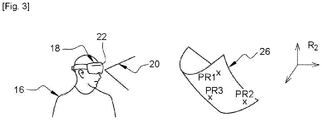
- an operator 16 is equipped with augmented reality equipment 18, such as glasses for example, configured to display in the field of vision 20 of the operator 16 at least one item of information.
- augmented reality equipment 18 such as glasses for example
- This augmented reality equipment 18 comprises a screen 22 and it is configured to display on the screen 22, in the field of vision 20 of the operator 16, at least one pointer 24 (visible on the figure 4 ).
- the augmented reality equipment 18 comprises at least one software configured to display the pointer 24 and determine the coordinates of the pointer 24 in a second frame R2 associated with a real environment.
- a real part 26 corresponding to the virtual part 12 is viewed by the operator 16 with the augmented reality device 18, the pointer 24 being displayed on the screen 22 superimposed on the real part 26.
- This real part 26 can include at least one defect 28 at the end of its manufacturing process.
- the real part 26 is identical to the virtual part 12. To each real point of the real part 26 corresponds a virtual point of the virtual part 12.
- a method for displaying at least one acceptance criterion comprises a calibration step consisting in determining a transition matrix to convert coordinates of a real point located in the second frame R2 into coordinates of a virtual point located in the first reference R1 and corresponding to the real point.
- an inverse passage matrix can be determined in order to convert coordinates of a virtual point located in the first frame R1 into coordinates of a real point located in the second frame R2 and corresponding to the virtual point.
- This calibration step consists in selecting at least three virtual calibration points P1, P2, P3 located, in the first reference R1, on the virtual model 10 of the aircraft and determining coordinates in the first reference R1 for each virtual point of calibration P1, P2, P3. As illustrated on the figure 2 , the virtual calibration points P1, P2, P3 are positioned on the virtual part 12.
- the real part 26 has a real calibration point PR1, PR2, PR3 which corresponds to said virtual calibration point P1, P2, P3.
- the virtual calibration points P1, P2, P2 are remarkable points and chosen so that the corresponding real calibration points PR1, PR2, PR3 are easily identifiable on the real part 26.
- the calibration step also consists in determining coordinates in the second reference frame R2 for each real calibration point PR1, PR2, PR3 of the real part 26.
- the augmented reality equipment 18 is used to carry out this step, the pointer 24 targeting, in turn, each of the real calibration points PR1, PR2, PR3.
- the passage matrix can be determined.
- the coordinates of the point in the first frame R1, corresponding to that of the virtual model 10 of the aircraft, are displayed on the screen 22 of the augmented reality equipment 18.
- the first and second frames R1 and R2 are orthonormal frames and the coordinates of a virtual or real point include three coordinates referenced X, Y, Z.
- the various steps of the location method are carried out statically, the coordinates of the point to be located being determined as a function of a static position of the pointer 24 targeting the point to be located.
- the various steps of the location method are carried out dynamically, the coordinates of the point to be located being determined in real time and changing according to the real time position of the mobile pointer 24 in the second marker R2.
- the coordinates of the point to be located can be determined and displayed as a function of the position of the pointer 24, without the latter necessarily being the target of a fault 28.
- the point to be located can be any element of a part or of an assembly. such as a particular attachment, hole or geometry.
- the coordinates in the first frame R1 of the point to be located pointed by the pointer 24 are determined, in real time, from the passage matrix and the coordinates in the second frame R2 of the pointer 24.
- the digital part file F12 of the virtual part 12 is converted or exported into a file usable by the software implemented in the augmented reality equipment 18.
- the step of displaying the virtual part 12 superimposed on the real part 26 is carried out by making the real calibration points PR1, PR2, PR3 of the real part 26 coincide with the virtual calibration points P1, P2, P3 of virtual part 12 and/or using the pass matrix or the inverse pass matrix.
- the representation of the virtual part 12 superimposed on the real part 26 is not necessary.
- Augmented reality equipment 18 can be configured to capture such an image.
- the method of the invention makes it possible to eliminate manual measurement and to automate the determination of the coordinates of a defect in the reference frame of a virtual model of an aircraft.
Landscapes
- Engineering & Computer Science (AREA)
- Physics & Mathematics (AREA)
- General Physics & Mathematics (AREA)
- Theoretical Computer Science (AREA)
- Computer Vision & Pattern Recognition (AREA)
- General Engineering & Computer Science (AREA)
- Quality & Reliability (AREA)
- Computer Graphics (AREA)
- Computer Hardware Design (AREA)
- Software Systems (AREA)
- Human Computer Interaction (AREA)
- Health & Medical Sciences (AREA)
- Life Sciences & Earth Sciences (AREA)
- Chemical & Material Sciences (AREA)
- Analytical Chemistry (AREA)
- Biochemistry (AREA)
- General Health & Medical Sciences (AREA)
- Immunology (AREA)
- Pathology (AREA)
- Processing Or Creating Images (AREA)
Abstract
- une étape de détermination d'une matrice de passage entre un repère dans lequel évolue le pointeur (24) et un repère dans lequel est définie la pièce virtuelle correspondant à la pièce réelle (26),
- une étape de détermination des coordonnées dans le premier repère du point à localiser en convertissant, grâce à la matrice de passage, les coordonnées dans le deuxième repère du pointeur (24) pointé sur le point à localiser.

Description
- La présente demande se rapporte à un procédé de localisation d'au moins un point d'une pièce réelle sur une maquette numérique.
- Lors d'une opération d'inspection qualité d'une pièce réelle, un opérateur doit localiser le plus précisément possible chaque défaut. En suivant, pour chaque défaut, un point virtuel correspondant au défaut localisé est positionné sur une maquette numérique afin de déterminer comment ce défaut peut être traité.
- Selon un mode opératoire, le défaut est localisé sur la pièce réelle en utilisant des moyens de mesure manuels comme un réglet par exemple. Une fois que les coordonnées du point localisé sur la pièce réelle sont déterminées dans le repère de la pièce, ces coordonnées doivent être converties dans le repère de la maquette numérique afin que le point localisé sur la pièce réelle soit correctement positionné sur la maquette numérique.
- Ce mode opératoire n'est pas satisfaisant car il peut s'avérer complexe de réaliser une mesure précise dans le cas d'une pièce de grandes dimensions, complexe et/ou sans référentiel visuel. La présente invention vise à remédier à tout ou partie des inconvénients de l'art antérieur.
- A cet effet, l'invention a pour objet un procédé de localisation d'au moins un point d'une pièce réelle sur une pièce virtuelle définie dans un premier repère, caractérisé en ce que le procédé comprend :
- une étape de visualisation de la pièce réelle avec un dispositif de réalité augmentée configuré pour afficher un pointeur en superposition de la pièce réelle et déterminer des coordonnées du pointeur dans un deuxième repère,
- une étape de détermination d'une matrice de passage pour convertir des coordonnées d'un point réel situé dans le deuxième repère en coordonnées d'un point virtuel situé dans le premier repère et correspondant au point réel,
- une étape de positionnement du pointeur de manière à ce qu'il pointe sur le point à localiser, et
- une étape de détermination des coordonnées dans le premier repère du point à localiser en convertissant grâce à la matrice de passage les coordonnées dans le deuxième repère du pointeur pointé sur le point à localiser.
- Le procédé de l'invention permet de supprimer la prise de mesure manuelle et d'automatiser la détermination des coordonnées d'un point d'une pièce réelle, comme un défaut par exemple, dans le repère d'une maquette virtuelle d'un aéronef.
- Selon une autre caractéristique, l'étape de détermination de la matrice de passage consiste à déterminer des coordonnées d'au moins trois points virtuels de calibration dans le premier repère, pour chaque point virtuel de calibration dans le premier repère correspondant à un point réel de calibration dans le deuxième repère, à déterminer des coordonnées dans le deuxième repère pour chaque point réel de calibration puis à déterminer la matrice de passage à partir des coordonnées de chaque point virtuel de calibration dans le premier repère et celles de chaque point réel de calibration dans le deuxième repère.
- Selon une autre caractéristique, les coordonnées dans le deuxième repère de chaque point réel de calibration sont déterminées en ciblant, tour à tour, avec le pointeur chacun des points réels de calibration.
- Selon une autre caractéristique, le procédé comprend une étape d'affichage de la pièce virtuelle superposée à la pièce réelle.
- Selon une autre caractéristique, les coordonnées du point à localiser sont déterminées en fonction d'une position statique du pointeur ciblant le point à localiser.
- Selon une autre caractéristique, les coordonnées du point à localiser évoluent en fonction de la position en temps réel du pointeur mobile dans le deuxième repère.
- Selon une autre caractéristique, le point à localier est un défaut de la pièce réelle.
- Selon une autre caractéristique, au moins une image de la pièce réelle, sur laquelle sont visibles le pointeur pointant le défaut ainsi que les coordonnées du point ciblé par le pointeur dans le premier repère, est prise.
- D'autres caractéristiques et avantages ressortiront de la description de l'invention qui va suivre, description donnée à titre d'exemple uniquement, en regard des dessins annexés parmi lesquels :
- La
figure 1 est une vue en perspective d'une maquette virtuelle d'un aéronef, - La
figure 2 est une représentation schématique d'une pièce virtuelle comportant trois points virtuels de calibration illustrant un mode de réalisation de l'invention, - La
figure 3 est une vue en perspective d'un opérateur équipé d'un équipement de réalité augmentée visualisant une pièce réelle comportant trois points réels de calibration illustrant un mode de réalisation de l'invention, et - La
figure 4 est une représentation du champ de vision d'un opérateur vu à travers un équipement de réalité augmentée lors d'une étape de prise de mesure illustrant un mode de réalisation de l'invention. - Sur la
figure 1 , on a représenté en 10 une maquette virtuelle d'un aéronef dans un premier repère R1. Cette maquette virtuelle 10 comprend une multitude de pièces virtuelles 12 ou d'assemblages de pièces. - Pour la présente demande, on entend par une pièce une seule pièce ou plusieurs pièces comme un assemblage de pièces par exemple.
- Comme illustré sur la
figure 2 , au moins une pièce virtuelle 12 est définie dans au moins un fichier numérique de pièce F12. La maquette virtuelle 10 de l'aéronef comprend une multitude de fichiers numériques de pièce F12. Les différents fichiers numériques de pièce F12 peuvent être stockés dans un dispositif de stockage 14. Ces différents fichiers numériques de pièce F12 peuvent être exportés et/ou convertis en tout fichier compatible avec un équipement de réalité augmentée. - A partir du fichier numérique de pièce F12, il est possible de visualiser, à l'aide d'un logiciel de visualisation adapté au fichier, une représentation de la pièce virtuelle12 dans le premier repère R1. Chaque point virtuel de la pièce virtuelle 12 présente des coordonnées exprimées dans le premier repère R1.
- A titre d'exemple, la pièce virtuelle 12 correspond à une partie d'une entrée d'air d'une nacelle d'un aéronef. Bien entendu, l'invention n'est pas limitée à cette pièce.
- Pour la mise en œuvre d'un procédé de localisation d'au moins un point d'une pièce réelle, comme illustré sur la
figure 3 , un opérateur 16 est équipé d'un équipement de réalité augmentée 18, comme des lunettes par exemple, configuré pour afficher dans le champ de vision 20 de l'opérateur 16 au moins une information. - Cet équipement de réalité augmentée 18 comprend un écran 22 et il est configuré pour afficher sur l'écran 22, dans le champ de vision 20 de l'opérateur 16, au moins un pointeur 24 (visible sur la
figure 4 ). - L'équipement de réalité augmentée 18 comprend au moins un logiciel configuré pour afficher le pointeur 24 et déterminer les coordonnées du pointeur 24 dans un deuxième repère R2 associé à un environnement réel.
- Comme illustré sur la
figure 4 , une pièce réelle 26 correspondant à la pièce virtuelle 12 est visualisée par l'opérateur 16 avec le dispositif de réalité augmentée 18, le pointeur 24 s'affichant sur l'écran 22 en superposition de la pièce réelle 26. Cette pièce réelle 26 peut comprendre au moins un défaut 28 à l'issue de son procédé de fabrication. - La pièce réelle 26 est identique à la pièce virtuelle 12. A chaque point réel de la pièce réelle 26 correspond un point virtuel de la pièce virtuelle 12.
- Selon un mode opératoire, un procédé de visualisation d'au moins un critère d'acceptation comprend une étape de calibration consistant à déterminer une matrice de passage pour convertir des coordonnées d'un point réel situé dans le deuxième repère R2 en coordonnées d'un point virtuel situé dans le premier repère R1 et correspondant au point réel. Eventuellement, une matrice de passage inverse peut être déterminée afin de convertir des coordonnés d'un point virtuel situé dans le premier repère R1 en coordonnées d'un point réel situé dans le deuxième repère R2 et correspondant au point virtuel.
- Cette étape de calibration consiste à sélectionner au moins trois points virtuels de calibration P1, P2, P3 situés, dans le premier repère R1, sur la maquette virtuelle 10 de l'aéronef et déterminer des coordonnées dans le premier repère R1 pour chaque point virtuel de calibration P1, P2, P3. Comme illustré sur la
figure 2 , les points virtuels de calibration P1, P2, P3 sont positionnés sur la pièce virtuelle 12. - Pour chaque point virtuel de calibration P1, P2, P2, la pièce réelle 26 présente un point réel de calibration PR1, PR2, PR3 qui correspond au dit point virtuel de calibration P1, P2, P3. Les points virtuels de calibration P1, P2, P2 sont des points remarquables et choisis de manière à ce que les points réels de calibration PR1, PR2, PR3 correspondants soient facilement identifiables sur la pièce réelle 26.
- L'étape de calibration consiste également à déterminer des coordonnées dans le deuxième repère R2 pour chaque point réel de calibration PR1, PR2, PR3 de la pièce réelle 26. Selon un mode opératoire, l'équipement de réalité augmentée 18 est utilisé pour réaliser cette étape, le pointeur 24 ciblant, tour à tour, chacun des points réels de calibration PR1, PR2, PR3.
- Connaissant les coordonnées de chaque point virtuel de calibration P1, P2, P3 dans le premier repère R1 et celles de chaque point réel de calibration PR1, PR2, PR3 dans le deuxième repère R2, la matrice de passage peut être déterminée.
- Cette étape de calibration peut être réalisée une seule fois pour chaque pièce réelle 26. Elle n'a pas besoin d'être répétée entre la localisation de deux points sur la même pièce réelle 26. Le procédé de localisation d'au moins un point, comme un défaut 28 par exemple, comprend les étapes suivantes :
- d'affichage sur l'écran 22 de l'équipement de réalité augmentée 20 de la pièce virtuelle 12 en superposition de la pièce réelle 26,
- de positionnement du pointeur 24 de l'équipement de réalité augmentée 18 de manière à ce qu'il cible le point réel à localiser,
- de détermination des coordonnées dans le deuxième repère R2 du pointeur 24 pointé sur le point à localiser,
- de détermination des coordonnées dans le premier repère R1 du point à localiser en convertissant grâce à la matrice de passage les coordonnées dans le deuxième repère R2 du pointeur 24 pointé sur le point à localiser.
- Selon un mode de réalisation, les coordonnées du point dans le premier repère R1, correspondant à celui de la maquette virtuelle 10 de l'aéronef, sont affichées sur l'écran 22 de l'équipement de réalité augmentée 18.
- Les premier et deuxième repères R1 et R2 sont des repères orthonormés et les coordonnées d'un point virtuel ou réel comprennent trois coordonnées référencées X, Y, Z.
- Selon un premier mode opératoire, les différentes étapes du procédé de localisation sont réalisées en statique, les coordonnées du point à localiser étant déterminées en fonction d'une position statique du pointeur 24 ciblant le point à localiser.
- Selon un deuxième mode opératoire, les différentes étapes du procédé de localisation sont réalisées en dynamique, les coordonnées du point à localiser étant déterminées en temps réel et évoluant en fonction de la position en temps réel du pointeur 24 mobile dans le deuxième repère R2.
- Les coordonnées du point à localiser peuvent être déterminées et affichées en fonction de la position du pointeur 24, sans que nécessairement ce dernier ne cible de défaut 28. Ainsi, le point à localiser peut être tout élément d'une pièce ou d'un assemblage comme une fixation, un orifice ou une géométrie particulière.
- Ainsi, les coordonnées dans le premier repère R1 du point à localiser pointé par le pointeur 24 sont déterminées, en temps réel, à partir de la matrice de passage et des coordonnées dans le deuxième repère R2 du pointeur 24.
- Pour afficher la pièce virtuelle 12 correspondant à la pièce réelle 26, le fichier numérique de pièce F12 de la pièce virtuelle 12 est converti ou exporté en un fichier exploitable par le logiciel implémenté dans l'équipement de réalité augmentée 18.
- Selon un mode opératoire, l'étape d'affichage de la pièce virtuelle 12 superposée sur la pièce réelle 26 est réalisée en faisant coïncider les points réels de calibration PR1, PR2, PR3 de la pièce réelle 26 et les points virtuels de calibration P1, P2, P3 de la pièce virtuelle 12 et/ou en utilisant la matrice de passage ou la matrice de passage inverse.
- Selon un mode de réalisation, la représentation de la pièce virtuelle 12 superposée sur la pièce réelle 26 n'est pas nécessaire.
- Pour faciliter le traitement du défaut, au moins une image de la pièce réelle 26, sur laquelle sont visibles le pointeur 24 pointant le défaut 28 détecté ainsi que les coordonnées du point ciblé par le pointeur 24 dans le premier repère R1 correspondant à celui de la maquette virtuelle 10, est prise.
- L'équipement de réalité augmentée 18 peut être configuré pour saisir une telle image.
- Le fait de pointer un point réel d'une pièce réelle 26 avec un pointeur 24 d'un équipement de réalité augmentée 18 simplifie la prise de mesure et permet d'obtenir une meilleure précision. Le procédé de l'invention permet de supprimer la prise de mesure manuelle et d'automatiser la détermination des coordonnées d'un défaut dans le repère d'une maquette virtuelle d'un aéronef.
Claims (8)
- Procédé de localisation d'au moins un point d'une pièce réelle (26) sur une pièce virtuelle (12) définie dans un premier repère (R1), caractérisé en ce que le procédé comprend :- une étape de visualisation de la pièce réelle (26) avec un dispositif de réalité augmentée (18) configuré pour afficher un pointeur (24) en superposition de la pièce réelle (26) et déterminer des coordonnées du pointeur (24) dans un deuxième repère (R2),- une étape de détermination d'une matrice de passage pour convertir des coordonnées d'un point réel situé dans le deuxième repère (R2) en coordonnées d'un point virtuel situé dans le premier repère (R1) et correspondant au point réel,- une étape de positionnement du pointeur (24) de manière à ce qu'il pointe sur le point à localiser, et- une étape de détermination des coordonnées dans le premier repère (R1) du point à localiser en convertissant grâce à la matrice de passage les coordonnées dans le deuxième repère (R2) du pointeur (24) pointé sur le point à localiser.
- Procédé de localisation d'au moins un point d'une pièce réelle (26) sur une pièce virtuelle (12) selon la revendication 1, caractérisé en ce que l'étape de détermination de la matrice de passage consiste à déterminer des coordonnées d'au moins trois points virtuels de calibration (P1, P2, P3) dans le premier repère (R1), pour chaque point virtuel de calibration (P1, P2, P3) dans le premier repère (R1) correspondant à un point réel de calibration (PR1, PR2, PR3) dans le deuxième repère (R2), à déterminer des coordonnées dans le deuxième repère (R2) pour chaque point réel de calibration (PR1, PR2, PR3) puis à déterminer la matrice de passage à partir des coordonnées de chaque point virtuel de calibration (P1, P2, P3) dans le premier repère (R1) et celles de chaque point réel de calibration (PR1, PR2, PR3) dans le deuxième repère (R2).
- Procédé de localisation d'au moins un point d'une pièce réelle (26) sur une pièce virtuelle (12) selon la revendication précédente, caractérisé en ce que les coordonnées dans le deuxième repère (R2) de chaque point réel de calibration (PR1, PR2, PR3) sont déterminées en ciblant, tour à tour, avec le pointeur (24) chacun des points réels de calibration (PR1, PR2, PR3).
- Procédé de localisation d'au moins un point d'une pièce réelle (26) sur une pièce virtuelle (12) selon la revendication précédente, caractérisé en ce que le procédé comprend une étape d'affichage de la pièce virtuelle (12) superposée à la pièce réelle (26).
- Procédé de localisation d'au moins un point d'une pièce réelle (26) sur une pièce virtuelle (12) selon l'une des revendications précédentes, caractérisé en ce que les coordonnées du point à localiser sont déterminées en fonction d'une position statique du pointeur (24) ciblant le point à localiser.
- Procédé de localisation d'au moins un point d'une pièce réelle (26) sur une pièce virtuelle (12) selon l'une des revendications 1 à 4, caractérisé en ce que les coordonnées du point à localiser évoluent en fonction de la position en temps réel du pointeur (24) mobile dans le deuxième repère (R2).
- Procédé de localisation d'au moins un point d'une pièce réelle (26) sur une pièce virtuelle (12) selon l'une des revendications, caractérisé en ce que le point à localier est un défaut (28) de la pièce réelle (26).
- Procédé de localisation d'au moins un point d'une pièce réelle (26) sur une pièce virtuelle (12) selon la revendication précédente, caractérisé en ce qu'au moins une image de la pièce réelle (26), sur laquelle sont visibles le pointeur (24) pointant le défaut (28) ainsi que les coordonnées du point pointé par le pointeur (24) dans le premier repère (R1), est prise.
Applications Claiming Priority (1)
| Application Number | Priority Date | Filing Date | Title |
|---|---|---|---|
| FR2106219A FR3123984A1 (fr) | 2021-06-14 | 2021-06-14 | Procédé de localisation d’au moins un point d’une pièce réelle sur une maquette numérique |
Publications (2)
| Publication Number | Publication Date |
|---|---|
| EP4105595A1 true EP4105595A1 (fr) | 2022-12-21 |
| EP4105595B1 EP4105595B1 (fr) | 2023-08-23 |
Family
ID=77317094
Family Applications (1)
| Application Number | Title | Priority Date | Filing Date |
|---|---|---|---|
| EP22176748.6A Active EP4105595B1 (fr) | 2021-06-14 | 2022-06-01 | Procédé de localisation d'au moins un point d'une pièce réelle sur une maquette numérique |
Country Status (4)
| Country | Link |
|---|---|
| US (1) | US20220398815A1 (fr) |
| EP (1) | EP4105595B1 (fr) |
| CN (1) | CN115482270A (fr) |
| FR (1) | FR3123984A1 (fr) |
Citations (3)
| Publication number | Priority date | Publication date | Assignee | Title |
|---|---|---|---|---|
| EP2641661B1 (fr) * | 2012-03-20 | 2016-05-11 | Hexagon Technology Center GmbH | Système d'application graphique |
| US9448758B2 (en) * | 2012-07-18 | 2016-09-20 | The Boeing Company | Projecting airplane location specific maintenance history using optical reference points |
| US10573089B2 (en) * | 2017-11-09 | 2020-02-25 | The Boeing Company | Systems, methods, and tools for spatially-registering virtual content with physical environment in augmented reality platforms |
Family Cites Families (14)
| Publication number | Priority date | Publication date | Assignee | Title |
|---|---|---|---|---|
| US10802665B2 (en) * | 2016-10-05 | 2020-10-13 | Motorola Solutions, Inc. | System and method for projecting graphical objects |
| US10140773B2 (en) * | 2017-02-01 | 2018-11-27 | Accenture Global Solutions Limited | Rendering virtual objects in 3D environments |
| US9892564B1 (en) * | 2017-03-30 | 2018-02-13 | Novarad Corporation | Augmenting real-time views of a patient with three-dimensional data |
| US10824867B1 (en) * | 2017-08-02 | 2020-11-03 | State Farm Mutual Automobile Insurance Company | Augmented reality system for real-time damage assessment |
| US10859831B1 (en) * | 2018-05-16 | 2020-12-08 | Facebook Technologies, Llc | Systems and methods for safely operating a mobile virtual reality system |
| US11024096B2 (en) * | 2019-04-29 | 2021-06-01 | The Board Of Trustees Of The Leland Stanford Junior University | 3D-perceptually accurate manual alignment of virtual content with the real world with an augmented reality device |
| CN110716645A (zh) * | 2019-10-15 | 2020-01-21 | 北京市商汤科技开发有限公司 | 一种增强现实数据呈现方法、装置、电子设备及存储介质 |
| US11003308B1 (en) * | 2020-02-03 | 2021-05-11 | Apple Inc. | Systems, methods, and graphical user interfaces for annotating, measuring, and modeling environments |
| JP7547504B2 (ja) * | 2020-12-10 | 2024-09-09 | マクセル株式会社 | 表示装置および表示方法 |
| FR3117642B1 (fr) * | 2020-12-16 | 2023-05-05 | Schneider Electric Ind Sas | Procédé pour la configuration et l’affichage en réalité augmentée ou mixte ou étendue des informations relatives à un équipement installé dans un site réel, produit programme d’ordinateur et dispositif électronique associés |
| KR102319649B1 (ko) * | 2021-03-10 | 2021-10-29 | 세종대학교산학협력단 | 혼합현실에서의 드론 비행을 위한 원격 훈련 방법 및 장치 |
| FR3124007A1 (fr) * | 2021-06-14 | 2022-12-16 | Airbus Operations (S.A.S.) | Procédé de visualisation d’au moins un critère d’acceptation en fonction d’un point d’une pièce ciblé |
| AU2022384283A1 (en) * | 2021-11-12 | 2024-05-30 | Materialise Nv | Systems, methods and devices for augmented reality assisted surgery |
| US11682180B1 (en) * | 2021-12-09 | 2023-06-20 | Qualcomm Incorporated | Anchoring virtual content to physical surfaces |
-
2021
- 2021-06-14 FR FR2106219A patent/FR3123984A1/fr not_active Ceased
-
2022
- 2022-05-11 CN CN202210511765.6A patent/CN115482270A/zh active Pending
- 2022-06-01 EP EP22176748.6A patent/EP4105595B1/fr active Active
- 2022-06-09 US US17/836,608 patent/US20220398815A1/en not_active Abandoned
Patent Citations (3)
| Publication number | Priority date | Publication date | Assignee | Title |
|---|---|---|---|---|
| EP2641661B1 (fr) * | 2012-03-20 | 2016-05-11 | Hexagon Technology Center GmbH | Système d'application graphique |
| US9448758B2 (en) * | 2012-07-18 | 2016-09-20 | The Boeing Company | Projecting airplane location specific maintenance history using optical reference points |
| US10573089B2 (en) * | 2017-11-09 | 2020-02-25 | The Boeing Company | Systems, methods, and tools for spatially-registering virtual content with physical environment in augmented reality platforms |
Also Published As
| Publication number | Publication date |
|---|---|
| CN115482270A (zh) | 2022-12-16 |
| FR3123984A1 (fr) | 2022-12-16 |
| US20220398815A1 (en) | 2022-12-15 |
| EP4105595B1 (fr) | 2023-08-23 |
Similar Documents
| Publication | Publication Date | Title |
|---|---|---|
| EP0487415B1 (fr) | Procédé de contrôle de mesures dimensionnelles de pièces de fonderie | |
| CN104655018B (zh) | 一种花键套端面尺寸检测系统及方法 | |
| US20130258313A1 (en) | Image analysis system and methods for ir optics | |
| FR2983960A1 (fr) | Systeme et procede pour controler une piece a l'aide de doubles dispositifs robotiques multi-axes | |
| JP6816971B2 (ja) | ひずみセンサを解析し、タービン部品のひずみを監視するためのデータ取得装置、システム、および方法 | |
| Le Sant et al. | Surface pressure measurements by using pressure-sensitive paints | |
| CA2681052A1 (fr) | Systeme de test universel apte a controler une pluralite de parametres relatifs au fonctionnement de dispositif de presentation d'informations optoelectroniques de types varies | |
| FR3087254A1 (fr) | Configuration d'un dispositif de controle non destructif | |
| WO2018065731A1 (fr) | Procédé de localisation de défaut dans des harnais électriques | |
| Shi et al. | 3D surface pressure measurement with single light-field camera and pressure-sensitive paint | |
| EP4105595B1 (fr) | Procédé de localisation d'au moins un point d'une pièce réelle sur une maquette numérique | |
| US20170178315A1 (en) | Image measuring method and image measuring device | |
| US9464890B2 (en) | Dynamic data acquisition, and apparatus and methods therefor | |
| EP4105922A1 (fr) | Procédé de fabrication d'une pièce réelle permettant de visualiser au moins un critère d'acceptation en fonction d'un point de la pièce ciblé | |
| Harding | Engineering precision | |
| US20240273706A1 (en) | Inspecting parts using geometric models | |
| WO2013023787A1 (fr) | Détermination de la position de sous-ouvertures sur un échantillon lors de mesures de surface sur l'échantillon | |
| FR3103609A1 (fr) | Procédé et système de localisation d’indications sur une pièce de moteur d’aéronef | |
| RU2829971C1 (ru) | Способ проведения технологических работ по обслуживанию газотурбинного двигателя | |
| US20250071251A1 (en) | System and method for locating and visualizing camera images in relation to a large-scale manufacturing product | |
| DE10102542B4 (de) | Anordnung zur visuellen Inspektion von Substraten | |
| Wernet | Real-time Fourier Background-oriented Schlieren | |
| Smith et al. | IMU and digital aerial camera misalignment calibration | |
| WO2025088900A1 (fr) | Système d'inspection de défauts et procédé d'inspection de défauts | |
| CN119806373A (zh) | 一种观瞄装备视景仿真方法 |
Legal Events
| Date | Code | Title | Description |
|---|---|---|---|
| PUAI | Public reference made under article 153(3) epc to a published international application that has entered the european phase |
Free format text: ORIGINAL CODE: 0009012 |
|
| STAA | Information on the status of an ep patent application or granted ep patent |
Free format text: STATUS: REQUEST FOR EXAMINATION WAS MADE |
|
| 17P | Request for examination filed |
Effective date: 20220601 |
|
| AK | Designated contracting states |
Kind code of ref document: A1 Designated state(s): AL AT BE BG CH CY CZ DE DK EE ES FI FR GB GR HR HU IE IS IT LI LT LU LV MC MK MT NL NO PL PT RO RS SE SI SK SM TR |
|
| GRAP | Despatch of communication of intention to grant a patent |
Free format text: ORIGINAL CODE: EPIDOSNIGR1 |
|
| STAA | Information on the status of an ep patent application or granted ep patent |
Free format text: STATUS: GRANT OF PATENT IS INTENDED |
|
| RIC1 | Information provided on ipc code assigned before grant |
Ipc: G01N 21/88 20060101ALN20230126BHEP Ipc: B64F 5/60 20170101ALI20230126BHEP Ipc: G06T 7/73 20170101ALI20230126BHEP Ipc: G06T 7/33 20170101ALI20230126BHEP Ipc: G06F 3/01 20060101ALI20230126BHEP Ipc: G01N 21/95 20060101ALI20230126BHEP Ipc: G01B 11/00 20060101AFI20230126BHEP |
|
| INTG | Intention to grant announced |
Effective date: 20230210 |
|
| GRAS | Grant fee paid |
Free format text: ORIGINAL CODE: EPIDOSNIGR3 |
|
| GRAA | (expected) grant |
Free format text: ORIGINAL CODE: 0009210 |
|
| STAA | Information on the status of an ep patent application or granted ep patent |
Free format text: STATUS: THE PATENT HAS BEEN GRANTED |
|
| RBV | Designated contracting states (corrected) |
Designated state(s): AL AT BE BG CH CY CZ DE DK EE ES FI FR GB GR HR HU IE IS IT LI LT LU LV MC MK MT NL NO PL PT RO RS SE SI SK SM TR |
|
| AK | Designated contracting states |
Kind code of ref document: B1 Designated state(s): AL AT BE BG CH CY CZ DE DK EE ES FI FR GB GR HR HU IE IS IT LI LT LU LV MC MK MT NL NO PL PT RO RS SE SI SK SM TR |
|
| REG | Reference to a national code |
Ref country code: GB Ref legal event code: FG4D Free format text: NOT ENGLISH |
|
| REG | Reference to a national code |
Ref country code: CH Ref legal event code: EP |
|
| REG | Reference to a national code |
Ref country code: IE Ref legal event code: FG4D Free format text: LANGUAGE OF EP DOCUMENT: FRENCH |
|
| REG | Reference to a national code |
Ref country code: DE Ref legal event code: R096 Ref document number: 602022000376 Country of ref document: DE |
|
| REG | Reference to a national code |
Ref country code: LT Ref legal event code: MG9D |
|
| REG | Reference to a national code |
Ref country code: NL Ref legal event code: MP Effective date: 20230823 |
|
| REG | Reference to a national code |
Ref country code: AT Ref legal event code: MK05 Ref document number: 1603095 Country of ref document: AT Kind code of ref document: T Effective date: 20230823 |
|
| PG25 | Lapsed in a contracting state [announced via postgrant information from national office to epo] |
Ref country code: GR Free format text: LAPSE BECAUSE OF FAILURE TO SUBMIT A TRANSLATION OF THE DESCRIPTION OR TO PAY THE FEE WITHIN THE PRESCRIBED TIME-LIMIT Effective date: 20231124 |
|
| PG25 | Lapsed in a contracting state [announced via postgrant information from national office to epo] |
Ref country code: IS Free format text: LAPSE BECAUSE OF FAILURE TO SUBMIT A TRANSLATION OF THE DESCRIPTION OR TO PAY THE FEE WITHIN THE PRESCRIBED TIME-LIMIT Effective date: 20231223 |
|
| PG25 | Lapsed in a contracting state [announced via postgrant information from national office to epo] |
Ref country code: SE Free format text: LAPSE BECAUSE OF FAILURE TO SUBMIT A TRANSLATION OF THE DESCRIPTION OR TO PAY THE FEE WITHIN THE PRESCRIBED TIME-LIMIT Effective date: 20230823 Ref country code: RS Free format text: LAPSE BECAUSE OF FAILURE TO SUBMIT A TRANSLATION OF THE DESCRIPTION OR TO PAY THE FEE WITHIN THE PRESCRIBED TIME-LIMIT Effective date: 20230823 Ref country code: PT Free format text: LAPSE BECAUSE OF FAILURE TO SUBMIT A TRANSLATION OF THE DESCRIPTION OR TO PAY THE FEE WITHIN THE PRESCRIBED TIME-LIMIT Effective date: 20231226 Ref country code: NO Free format text: LAPSE BECAUSE OF FAILURE TO SUBMIT A TRANSLATION OF THE DESCRIPTION OR TO PAY THE FEE WITHIN THE PRESCRIBED TIME-LIMIT Effective date: 20231123 Ref country code: NL Free format text: LAPSE BECAUSE OF FAILURE TO SUBMIT A TRANSLATION OF THE DESCRIPTION OR TO PAY THE FEE WITHIN THE PRESCRIBED TIME-LIMIT Effective date: 20230823 Ref country code: LV Free format text: LAPSE BECAUSE OF FAILURE TO SUBMIT A TRANSLATION OF THE DESCRIPTION OR TO PAY THE FEE WITHIN THE PRESCRIBED TIME-LIMIT Effective date: 20230823 Ref country code: LT Free format text: LAPSE BECAUSE OF FAILURE TO SUBMIT A TRANSLATION OF THE DESCRIPTION OR TO PAY THE FEE WITHIN THE PRESCRIBED TIME-LIMIT Effective date: 20230823 Ref country code: IS Free format text: LAPSE BECAUSE OF FAILURE TO SUBMIT A TRANSLATION OF THE DESCRIPTION OR TO PAY THE FEE WITHIN THE PRESCRIBED TIME-LIMIT Effective date: 20231223 Ref country code: HR Free format text: LAPSE BECAUSE OF FAILURE TO SUBMIT A TRANSLATION OF THE DESCRIPTION OR TO PAY THE FEE WITHIN THE PRESCRIBED TIME-LIMIT Effective date: 20230823 Ref country code: GR Free format text: LAPSE BECAUSE OF FAILURE TO SUBMIT A TRANSLATION OF THE DESCRIPTION OR TO PAY THE FEE WITHIN THE PRESCRIBED TIME-LIMIT Effective date: 20231124 Ref country code: FI Free format text: LAPSE BECAUSE OF FAILURE TO SUBMIT A TRANSLATION OF THE DESCRIPTION OR TO PAY THE FEE WITHIN THE PRESCRIBED TIME-LIMIT Effective date: 20230823 Ref country code: AT Free format text: LAPSE BECAUSE OF FAILURE TO SUBMIT A TRANSLATION OF THE DESCRIPTION OR TO PAY THE FEE WITHIN THE PRESCRIBED TIME-LIMIT Effective date: 20230823 |
|
| PG25 | Lapsed in a contracting state [announced via postgrant information from national office to epo] |
Ref country code: PL Free format text: LAPSE BECAUSE OF FAILURE TO SUBMIT A TRANSLATION OF THE DESCRIPTION OR TO PAY THE FEE WITHIN THE PRESCRIBED TIME-LIMIT Effective date: 20230823 |
|
| PG25 | Lapsed in a contracting state [announced via postgrant information from national office to epo] |
Ref country code: ES Free format text: LAPSE BECAUSE OF FAILURE TO SUBMIT A TRANSLATION OF THE DESCRIPTION OR TO PAY THE FEE WITHIN THE PRESCRIBED TIME-LIMIT Effective date: 20230823 |
|
| PG25 | Lapsed in a contracting state [announced via postgrant information from national office to epo] |
Ref country code: SM Free format text: LAPSE BECAUSE OF FAILURE TO SUBMIT A TRANSLATION OF THE DESCRIPTION OR TO PAY THE FEE WITHIN THE PRESCRIBED TIME-LIMIT Effective date: 20230823 Ref country code: RO Free format text: LAPSE BECAUSE OF FAILURE TO SUBMIT A TRANSLATION OF THE DESCRIPTION OR TO PAY THE FEE WITHIN THE PRESCRIBED TIME-LIMIT Effective date: 20230823 Ref country code: ES Free format text: LAPSE BECAUSE OF FAILURE TO SUBMIT A TRANSLATION OF THE DESCRIPTION OR TO PAY THE FEE WITHIN THE PRESCRIBED TIME-LIMIT Effective date: 20230823 Ref country code: EE Free format text: LAPSE BECAUSE OF FAILURE TO SUBMIT A TRANSLATION OF THE DESCRIPTION OR TO PAY THE FEE WITHIN THE PRESCRIBED TIME-LIMIT Effective date: 20230823 Ref country code: DK Free format text: LAPSE BECAUSE OF FAILURE TO SUBMIT A TRANSLATION OF THE DESCRIPTION OR TO PAY THE FEE WITHIN THE PRESCRIBED TIME-LIMIT Effective date: 20230823 Ref country code: CZ Free format text: LAPSE BECAUSE OF FAILURE TO SUBMIT A TRANSLATION OF THE DESCRIPTION OR TO PAY THE FEE WITHIN THE PRESCRIBED TIME-LIMIT Effective date: 20230823 Ref country code: SK Free format text: LAPSE BECAUSE OF FAILURE TO SUBMIT A TRANSLATION OF THE DESCRIPTION OR TO PAY THE FEE WITHIN THE PRESCRIBED TIME-LIMIT Effective date: 20230823 |
|
| REG | Reference to a national code |
Ref country code: DE Ref legal event code: R097 Ref document number: 602022000376 Country of ref document: DE |
|
| PG25 | Lapsed in a contracting state [announced via postgrant information from national office to epo] |
Ref country code: IT Free format text: LAPSE BECAUSE OF FAILURE TO SUBMIT A TRANSLATION OF THE DESCRIPTION OR TO PAY THE FEE WITHIN THE PRESCRIBED TIME-LIMIT Effective date: 20230823 |
|
| PLBE | No opposition filed within time limit |
Free format text: ORIGINAL CODE: 0009261 |
|
| STAA | Information on the status of an ep patent application or granted ep patent |
Free format text: STATUS: NO OPPOSITION FILED WITHIN TIME LIMIT |
|
| 26N | No opposition filed |
Effective date: 20240524 |
|
| PG25 | Lapsed in a contracting state [announced via postgrant information from national office to epo] |
Ref country code: SI Free format text: LAPSE BECAUSE OF FAILURE TO SUBMIT A TRANSLATION OF THE DESCRIPTION OR TO PAY THE FEE WITHIN THE PRESCRIBED TIME-LIMIT Effective date: 20230823 |
|
| PG25 | Lapsed in a contracting state [announced via postgrant information from national office to epo] |
Ref country code: BG Free format text: LAPSE BECAUSE OF FAILURE TO SUBMIT A TRANSLATION OF THE DESCRIPTION OR TO PAY THE FEE WITHIN THE PRESCRIBED TIME-LIMIT Effective date: 20230823 |
|
| PG25 | Lapsed in a contracting state [announced via postgrant information from national office to epo] |
Ref country code: BG Free format text: LAPSE BECAUSE OF FAILURE TO SUBMIT A TRANSLATION OF THE DESCRIPTION OR TO PAY THE FEE WITHIN THE PRESCRIBED TIME-LIMIT Effective date: 20230823 |
|
| PG25 | Lapsed in a contracting state [announced via postgrant information from national office to epo] |
Ref country code: MC Free format text: LAPSE BECAUSE OF FAILURE TO SUBMIT A TRANSLATION OF THE DESCRIPTION OR TO PAY THE FEE WITHIN THE PRESCRIBED TIME-LIMIT Effective date: 20230823 |
|
| PG25 | Lapsed in a contracting state [announced via postgrant information from national office to epo] |
Ref country code: LU Free format text: LAPSE BECAUSE OF NON-PAYMENT OF DUE FEES Effective date: 20240601 |
|
| PG25 | Lapsed in a contracting state [announced via postgrant information from national office to epo] |
Ref country code: IE Free format text: LAPSE BECAUSE OF NON-PAYMENT OF DUE FEES Effective date: 20240601 |
|
| PG25 | Lapsed in a contracting state [announced via postgrant information from national office to epo] |
Ref country code: BE Free format text: LAPSE BECAUSE OF NON-PAYMENT OF DUE FEES Effective date: 20240630 |
|
| REG | Reference to a national code |
Ref country code: BE Ref legal event code: MM Effective date: 20240630 |
|
| PGFP | Annual fee paid to national office [announced via postgrant information from national office to epo] |
Ref country code: DE Payment date: 20250618 Year of fee payment: 4 |
|
| PGFP | Annual fee paid to national office [announced via postgrant information from national office to epo] |
Ref country code: FR Payment date: 20250627 Year of fee payment: 4 |
|
| PG25 | Lapsed in a contracting state [announced via postgrant information from national office to epo] |
Ref country code: CY Free format text: LAPSE BECAUSE OF FAILURE TO SUBMIT A TRANSLATION OF THE DESCRIPTION OR TO PAY THE FEE WITHIN THE PRESCRIBED TIME-LIMIT; INVALID AB INITIO Effective date: 20220601 |
|
| REG | Reference to a national code |
Ref country code: CH Ref legal event code: H13 Free format text: ST27 STATUS EVENT CODE: U-0-0-H10-H13 (AS PROVIDED BY THE NATIONAL OFFICE) Effective date: 20260127 |
|
| PG25 | Lapsed in a contracting state [announced via postgrant information from national office to epo] |
Ref country code: HU Free format text: LAPSE BECAUSE OF FAILURE TO SUBMIT A TRANSLATION OF THE DESCRIPTION OR TO PAY THE FEE WITHIN THE PRESCRIBED TIME-LIMIT; INVALID AB INITIO Effective date: 20220601 |
|
| PG25 | Lapsed in a contracting state [announced via postgrant information from national office to epo] |
Ref country code: CH Free format text: LAPSE BECAUSE OF NON-PAYMENT OF DUE FEES Effective date: 20250630 |