EP4105542A1 - Druckminderungsvorrichtung - Google Patents
Druckminderungsvorrichtung Download PDFInfo
- Publication number
- EP4105542A1 EP4105542A1 EP21179536.4A EP21179536A EP4105542A1 EP 4105542 A1 EP4105542 A1 EP 4105542A1 EP 21179536 A EP21179536 A EP 21179536A EP 4105542 A1 EP4105542 A1 EP 4105542A1
- Authority
- EP
- European Patent Office
- Prior art keywords
- pressure
- valve
- pressure reducing
- fluid circuit
- safety relief
- Prior art date
- Legal status (The legal status is an assumption and is not a legal conclusion. Google has not performed a legal analysis and makes no representation as to the accuracy of the status listed.)
- Pending
Links
- 239000012530 fluid Substances 0.000 claims abstract description 85
- 238000009434 installation Methods 0.000 claims abstract description 19
- 238000011144 upstream manufacturing Methods 0.000 claims abstract description 15
- 230000000740 bleeding effect Effects 0.000 claims description 24
- 230000009172 bursting Effects 0.000 claims description 7
- 239000007789 gas Substances 0.000 description 13
- 230000001105 regulatory effect Effects 0.000 description 4
- 239000002245 particle Substances 0.000 description 3
- 230000002441 reversible effect Effects 0.000 description 3
- 239000002360 explosive Substances 0.000 description 2
- 239000001257 hydrogen Substances 0.000 description 2
- 229910052739 hydrogen Inorganic materials 0.000 description 2
- 238000012423 maintenance Methods 0.000 description 2
- 230000007257 malfunction Effects 0.000 description 2
- 239000012528 membrane Substances 0.000 description 2
- 238000000034 method Methods 0.000 description 2
- 238000010926 purge Methods 0.000 description 2
- UFHFLCQGNIYNRP-UHFFFAOYSA-N Hydrogen Chemical compound [H][H] UFHFLCQGNIYNRP-UHFFFAOYSA-N 0.000 description 1
- 230000002159 abnormal effect Effects 0.000 description 1
- 230000004888 barrier function Effects 0.000 description 1
- 230000033228 biological regulation Effects 0.000 description 1
- 230000000295 complement effect Effects 0.000 description 1
- 230000002596 correlated effect Effects 0.000 description 1
- 230000007423 decrease Effects 0.000 description 1
- 230000007547 defect Effects 0.000 description 1
- 238000001514 detection method Methods 0.000 description 1
- 230000005611 electricity Effects 0.000 description 1
- 238000001914 filtration Methods 0.000 description 1
- 150000002431 hydrogen Chemical class 0.000 description 1
- JEIPFZHSYJVQDO-UHFFFAOYSA-N iron(III) oxide Inorganic materials O=[Fe]O[Fe]=O JEIPFZHSYJVQDO-UHFFFAOYSA-N 0.000 description 1
- 239000000463 material Substances 0.000 description 1
- 238000006386 neutralization reaction Methods 0.000 description 1
- 229920002635 polyurethane Polymers 0.000 description 1
- 239000004814 polyurethane Substances 0.000 description 1
- 230000002269 spontaneous effect Effects 0.000 description 1
- 231100000331 toxic Toxicity 0.000 description 1
- 230000002588 toxic effect Effects 0.000 description 1
- 238000009423 ventilation Methods 0.000 description 1
- 238000013022 venting Methods 0.000 description 1
Images


Classifications
-
- F—MECHANICAL ENGINEERING; LIGHTING; HEATING; WEAPONS; BLASTING
- F17—STORING OR DISTRIBUTING GASES OR LIQUIDS
- F17C—VESSELS FOR CONTAINING OR STORING COMPRESSED, LIQUEFIED OR SOLIDIFIED GASES; FIXED-CAPACITY GAS-HOLDERS; FILLING VESSELS WITH, OR DISCHARGING FROM VESSELS, COMPRESSED, LIQUEFIED, OR SOLIDIFIED GASES
- F17C13/00—Details of vessels or of the filling or discharging of vessels
- F17C13/04—Arrangement or mounting of valves
-
- F—MECHANICAL ENGINEERING; LIGHTING; HEATING; WEAPONS; BLASTING
- F17—STORING OR DISTRIBUTING GASES OR LIQUIDS
- F17C—VESSELS FOR CONTAINING OR STORING COMPRESSED, LIQUEFIED OR SOLIDIFIED GASES; FIXED-CAPACITY GAS-HOLDERS; FILLING VESSELS WITH, OR DISCHARGING FROM VESSELS, COMPRESSED, LIQUEFIED, OR SOLIDIFIED GASES
- F17C2205/00—Vessel construction, in particular mounting arrangements, attachments or identifications means
- F17C2205/03—Fluid connections, filters, valves, closure means or other attachments
- F17C2205/0302—Fittings, valves, filters, or components in connection with the gas storage device
- F17C2205/0311—Closure means
- F17C2205/0314—Closure means breakable, e.g. with burst discs
-
- F—MECHANICAL ENGINEERING; LIGHTING; HEATING; WEAPONS; BLASTING
- F17—STORING OR DISTRIBUTING GASES OR LIQUIDS
- F17C—VESSELS FOR CONTAINING OR STORING COMPRESSED, LIQUEFIED OR SOLIDIFIED GASES; FIXED-CAPACITY GAS-HOLDERS; FILLING VESSELS WITH, OR DISCHARGING FROM VESSELS, COMPRESSED, LIQUEFIED, OR SOLIDIFIED GASES
- F17C2205/00—Vessel construction, in particular mounting arrangements, attachments or identifications means
- F17C2205/03—Fluid connections, filters, valves, closure means or other attachments
- F17C2205/0302—Fittings, valves, filters, or components in connection with the gas storage device
- F17C2205/0323—Valves
- F17C2205/0332—Safety valves or pressure relief valves
-
- F—MECHANICAL ENGINEERING; LIGHTING; HEATING; WEAPONS; BLASTING
- F17—STORING OR DISTRIBUTING GASES OR LIQUIDS
- F17C—VESSELS FOR CONTAINING OR STORING COMPRESSED, LIQUEFIED OR SOLIDIFIED GASES; FIXED-CAPACITY GAS-HOLDERS; FILLING VESSELS WITH, OR DISCHARGING FROM VESSELS, COMPRESSED, LIQUEFIED, OR SOLIDIFIED GASES
- F17C2205/00—Vessel construction, in particular mounting arrangements, attachments or identifications means
- F17C2205/03—Fluid connections, filters, valves, closure means or other attachments
- F17C2205/0302—Fittings, valves, filters, or components in connection with the gas storage device
- F17C2205/0323—Valves
- F17C2205/0335—Check-valves or non-return valves
-
- F—MECHANICAL ENGINEERING; LIGHTING; HEATING; WEAPONS; BLASTING
- F17—STORING OR DISTRIBUTING GASES OR LIQUIDS
- F17C—VESSELS FOR CONTAINING OR STORING COMPRESSED, LIQUEFIED OR SOLIDIFIED GASES; FIXED-CAPACITY GAS-HOLDERS; FILLING VESSELS WITH, OR DISCHARGING FROM VESSELS, COMPRESSED, LIQUEFIED, OR SOLIDIFIED GASES
- F17C2205/00—Vessel construction, in particular mounting arrangements, attachments or identifications means
- F17C2205/03—Fluid connections, filters, valves, closure means or other attachments
- F17C2205/0302—Fittings, valves, filters, or components in connection with the gas storage device
- F17C2205/0338—Pressure regulators
-
- F—MECHANICAL ENGINEERING; LIGHTING; HEATING; WEAPONS; BLASTING
- F17—STORING OR DISTRIBUTING GASES OR LIQUIDS
- F17C—VESSELS FOR CONTAINING OR STORING COMPRESSED, LIQUEFIED OR SOLIDIFIED GASES; FIXED-CAPACITY GAS-HOLDERS; FILLING VESSELS WITH, OR DISCHARGING FROM VESSELS, COMPRESSED, LIQUEFIED, OR SOLIDIFIED GASES
- F17C2205/00—Vessel construction, in particular mounting arrangements, attachments or identifications means
- F17C2205/03—Fluid connections, filters, valves, closure means or other attachments
- F17C2205/0302—Fittings, valves, filters, or components in connection with the gas storage device
- F17C2205/0341—Filters
-
- F—MECHANICAL ENGINEERING; LIGHTING; HEATING; WEAPONS; BLASTING
- F17—STORING OR DISTRIBUTING GASES OR LIQUIDS
- F17C—VESSELS FOR CONTAINING OR STORING COMPRESSED, LIQUEFIED OR SOLIDIFIED GASES; FIXED-CAPACITY GAS-HOLDERS; FILLING VESSELS WITH, OR DISCHARGING FROM VESSELS, COMPRESSED, LIQUEFIED, OR SOLIDIFIED GASES
- F17C2205/00—Vessel construction, in particular mounting arrangements, attachments or identifications means
- F17C2205/03—Fluid connections, filters, valves, closure means or other attachments
- F17C2205/0302—Fittings, valves, filters, or components in connection with the gas storage device
- F17C2205/0382—Constructional details of valves, regulators
- F17C2205/0385—Constructional details of valves, regulators in blocks or units
-
- F—MECHANICAL ENGINEERING; LIGHTING; HEATING; WEAPONS; BLASTING
- F17—STORING OR DISTRIBUTING GASES OR LIQUIDS
- F17C—VESSELS FOR CONTAINING OR STORING COMPRESSED, LIQUEFIED OR SOLIDIFIED GASES; FIXED-CAPACITY GAS-HOLDERS; FILLING VESSELS WITH, OR DISCHARGING FROM VESSELS, COMPRESSED, LIQUEFIED, OR SOLIDIFIED GASES
- F17C2205/00—Vessel construction, in particular mounting arrangements, attachments or identifications means
- F17C2205/03—Fluid connections, filters, valves, closure means or other attachments
- F17C2205/0388—Arrangement of valves, regulators, filters
- F17C2205/0394—Arrangement of valves, regulators, filters in direct contact with the pressure vessel
-
- F—MECHANICAL ENGINEERING; LIGHTING; HEATING; WEAPONS; BLASTING
- F17—STORING OR DISTRIBUTING GASES OR LIQUIDS
- F17C—VESSELS FOR CONTAINING OR STORING COMPRESSED, LIQUEFIED OR SOLIDIFIED GASES; FIXED-CAPACITY GAS-HOLDERS; FILLING VESSELS WITH, OR DISCHARGING FROM VESSELS, COMPRESSED, LIQUEFIED, OR SOLIDIFIED GASES
- F17C2221/00—Handled fluid, in particular type of fluid
- F17C2221/01—Pure fluids
- F17C2221/012—Hydrogen
-
- F—MECHANICAL ENGINEERING; LIGHTING; HEATING; WEAPONS; BLASTING
- F17—STORING OR DISTRIBUTING GASES OR LIQUIDS
- F17C—VESSELS FOR CONTAINING OR STORING COMPRESSED, LIQUEFIED OR SOLIDIFIED GASES; FIXED-CAPACITY GAS-HOLDERS; FILLING VESSELS WITH, OR DISCHARGING FROM VESSELS, COMPRESSED, LIQUEFIED, OR SOLIDIFIED GASES
- F17C2221/00—Handled fluid, in particular type of fluid
- F17C2221/03—Mixtures
- F17C2221/037—Containing pollutant, e.g. H2S, Cl
-
- F—MECHANICAL ENGINEERING; LIGHTING; HEATING; WEAPONS; BLASTING
- F17—STORING OR DISTRIBUTING GASES OR LIQUIDS
- F17C—VESSELS FOR CONTAINING OR STORING COMPRESSED, LIQUEFIED OR SOLIDIFIED GASES; FIXED-CAPACITY GAS-HOLDERS; FILLING VESSELS WITH, OR DISCHARGING FROM VESSELS, COMPRESSED, LIQUEFIED, OR SOLIDIFIED GASES
- F17C2223/00—Handled fluid before transfer, i.e. state of fluid when stored in the vessel or before transfer from the vessel
- F17C2223/01—Handled fluid before transfer, i.e. state of fluid when stored in the vessel or before transfer from the vessel characterised by the phase
- F17C2223/0107—Single phase
- F17C2223/0123—Single phase gaseous, e.g. CNG, GNC
-
- F—MECHANICAL ENGINEERING; LIGHTING; HEATING; WEAPONS; BLASTING
- F17—STORING OR DISTRIBUTING GASES OR LIQUIDS
- F17C—VESSELS FOR CONTAINING OR STORING COMPRESSED, LIQUEFIED OR SOLIDIFIED GASES; FIXED-CAPACITY GAS-HOLDERS; FILLING VESSELS WITH, OR DISCHARGING FROM VESSELS, COMPRESSED, LIQUEFIED, OR SOLIDIFIED GASES
- F17C2223/00—Handled fluid before transfer, i.e. state of fluid when stored in the vessel or before transfer from the vessel
- F17C2223/03—Handled fluid before transfer, i.e. state of fluid when stored in the vessel or before transfer from the vessel characterised by the pressure level
- F17C2223/036—Very high pressure (>80 bar)
-
- F—MECHANICAL ENGINEERING; LIGHTING; HEATING; WEAPONS; BLASTING
- F17—STORING OR DISTRIBUTING GASES OR LIQUIDS
- F17C—VESSELS FOR CONTAINING OR STORING COMPRESSED, LIQUEFIED OR SOLIDIFIED GASES; FIXED-CAPACITY GAS-HOLDERS; FILLING VESSELS WITH, OR DISCHARGING FROM VESSELS, COMPRESSED, LIQUEFIED, OR SOLIDIFIED GASES
- F17C2225/00—Handled fluid after transfer, i.e. state of fluid after transfer from the vessel
- F17C2225/01—Handled fluid after transfer, i.e. state of fluid after transfer from the vessel characterised by the phase
- F17C2225/0107—Single phase
- F17C2225/0123—Single phase gaseous, e.g. CNG, GNC
-
- F—MECHANICAL ENGINEERING; LIGHTING; HEATING; WEAPONS; BLASTING
- F17—STORING OR DISTRIBUTING GASES OR LIQUIDS
- F17C—VESSELS FOR CONTAINING OR STORING COMPRESSED, LIQUEFIED OR SOLIDIFIED GASES; FIXED-CAPACITY GAS-HOLDERS; FILLING VESSELS WITH, OR DISCHARGING FROM VESSELS, COMPRESSED, LIQUEFIED, OR SOLIDIFIED GASES
- F17C2225/00—Handled fluid after transfer, i.e. state of fluid after transfer from the vessel
- F17C2225/03—Handled fluid after transfer, i.e. state of fluid after transfer from the vessel characterised by the pressure level
- F17C2225/036—Very high pressure, i.e. above 80 bars
-
- F—MECHANICAL ENGINEERING; LIGHTING; HEATING; WEAPONS; BLASTING
- F17—STORING OR DISTRIBUTING GASES OR LIQUIDS
- F17C—VESSELS FOR CONTAINING OR STORING COMPRESSED, LIQUEFIED OR SOLIDIFIED GASES; FIXED-CAPACITY GAS-HOLDERS; FILLING VESSELS WITH, OR DISCHARGING FROM VESSELS, COMPRESSED, LIQUEFIED, OR SOLIDIFIED GASES
- F17C2250/00—Accessories; Control means; Indicating, measuring or monitoring of parameters
- F17C2250/06—Controlling or regulating of parameters as output values
- F17C2250/0605—Parameters
- F17C2250/0626—Pressure
-
- F—MECHANICAL ENGINEERING; LIGHTING; HEATING; WEAPONS; BLASTING
- F17—STORING OR DISTRIBUTING GASES OR LIQUIDS
- F17C—VESSELS FOR CONTAINING OR STORING COMPRESSED, LIQUEFIED OR SOLIDIFIED GASES; FIXED-CAPACITY GAS-HOLDERS; FILLING VESSELS WITH, OR DISCHARGING FROM VESSELS, COMPRESSED, LIQUEFIED, OR SOLIDIFIED GASES
- F17C2250/00—Accessories; Control means; Indicating, measuring or monitoring of parameters
- F17C2250/06—Controlling or regulating of parameters as output values
- F17C2250/0605—Parameters
- F17C2250/0636—Flow or movement of content
-
- F—MECHANICAL ENGINEERING; LIGHTING; HEATING; WEAPONS; BLASTING
- F17—STORING OR DISTRIBUTING GASES OR LIQUIDS
- F17C—VESSELS FOR CONTAINING OR STORING COMPRESSED, LIQUEFIED OR SOLIDIFIED GASES; FIXED-CAPACITY GAS-HOLDERS; FILLING VESSELS WITH, OR DISCHARGING FROM VESSELS, COMPRESSED, LIQUEFIED, OR SOLIDIFIED GASES
- F17C2260/00—Purposes of gas storage and gas handling
- F17C2260/02—Improving properties related to fluid or fluid transfer
- F17C2260/021—Avoiding over pressurising
-
- F—MECHANICAL ENGINEERING; LIGHTING; HEATING; WEAPONS; BLASTING
- F17—STORING OR DISTRIBUTING GASES OR LIQUIDS
- F17C—VESSELS FOR CONTAINING OR STORING COMPRESSED, LIQUEFIED OR SOLIDIFIED GASES; FIXED-CAPACITY GAS-HOLDERS; FILLING VESSELS WITH, OR DISCHARGING FROM VESSELS, COMPRESSED, LIQUEFIED, OR SOLIDIFIED GASES
- F17C2260/00—Purposes of gas storage and gas handling
- F17C2260/03—Dealing with losses
- F17C2260/035—Dealing with losses of fluid
- F17C2260/036—Avoiding leaks
Definitions
- the invention relates to the field of valves for compressed gas.
- the invention relates to pressure reducing devices.
- Pressure reducing devices dedicated to high pressure fluids have been used for many years already. Pressure reducing devices allow to use high pressure sources, of for example 300 bar and higher, while remaining compatible with coupled installations that require a lower pressure inlet, of for example 200 bar and lower through the use of specifically made interfaces, i.e. valve delivery port specifically coded for such lower pressures as per applicable regulation/standard.
- a fluid's pressure and volume are correlated, as when the pressure increases, the volume decreases. Therefore, pressure reducing devices make the user's tasks easier as more gas can be stored in a higher-pressure vessel while keeping its volume small. Using a pressure reducing device will allow the user to have a desired pressure for the coupled installations that are typically designed for lower pressures, even if the stored fluid has a pressure being over the coupled installation's capacity. So, pressure reducing devices increase either usage autonomy at equivalent size of vessel, or increase portability, by reducing the vessel's size and weight.
- pressure reducing devices are, for example, used in standalone cylinders, as well as bundles and trailers. This feature is concretely achieved by implementing an integrated pressure unit within the cylinder valve body (for instance, main shutoff valve, pressure regulating unit, emergency shutoff valve and safety relief device are integrated in same body), or with separate elements (main shutoff valve, pressure regulating unit, emergency shutoff valve and safety relief device are different objects) within a dedicated gas panel on the bundles, tube trailers,...
- the downstream end of the pressure reducing device may comprise an outlet valve, or it can be just a simple connection or interface.
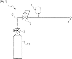
- the pressure reducing device comprises an operational fluid circuit 101 having an optional main shutoff valve 2 allowing the opening-up of the pressure reducing unit, a pressure regulating unit 3 reducing the pressure to a set desired value with a maximum pressure P A it can deliver, a safety relief device 6 opening itself in case of an excess pressure being higher than the maximum allowable pressure P A in the coupled downstream installation is present, and an outlet interface 5 that may comprise a valve, being connected to the coupled installation.
- the Safety relief device 6 is located downstream of the pressure reducing unit 3 to protect the lower pressure side of the system.
- the safety relief device 6 can for example be a safety relief valve or a bursting disc, being respectively reversible and single use.
- the safety relief device 6 is designed to open in case of an unexpected excess pressure being higher than the maximum allowable pressure in the coupled installation is being detected, this excess pressure can for example be due to a failure or malfunction of the pressure reducing unit 3.
- An outlet interface 5 can be configured in different manners, such as threaded joint, quick-connect, featuring a check-valve, a non-return valve, a shut-off valve.
- the outlet interface 5 has a determined pressure P N (e.g. 200bar) which corresponds either to its pressure capability or rating.
- P N e.g. 200bar
- an optional gas filter can be placed between the main shutoff valve 2 and the pressure reducing unit 3, but it is possible to be placed upstream of the main shutoff valve, and an optional non-return valve can be placed in the fluid circuit, downstream the emergency shutoff valve.
- the fluid contained might be a flammable medium such as hydrogen or other fluids creating dangerous and/or toxic environments, e.g. ATEX (Atmosphere Explosives).
- the safety relief device can be collected to a complimentary exhaust pipeline or equivalent, it would complicate the connection process to the installation by requiring additional setups and extra handling steps, for example extensive safety checks, relying on a procedural barrier.
- safety relief devices are mechanical components and are therefore prone to failure. Although these devices are designed to be highly reliable, malfunctions and defects should always be taken into consideration.
- the invention relates to a pressure reducing device comprising an upstream end configured to be connected to a pressurized gas source and a downstream end configured to be connected to a coupled installation and comprising:
- the invention solves the above-mentioned problems by implementing a failure safe feature on the pressure reducing device (PRD) that prevents any release of fluid to the atmosphere while requiring no external energy and no extra components such as a PLC system.
- PRD pressure reducing device
- the pressure increases in the PRD will lead to a spontaneous shutoff of the feeding flow, fully protecting the downstream coupled installation by shutting down the pressure source.
- the emergency shutoff valve will get actuated by the overpressure released through the safety relief device (SRD) in case of failure of the pressure reducing unit (PRU). So, instead of releasing the overpressure fluid to atmosphere, the invention allows to advantageously and safely shut down the gas stream.
- SRD safety relief device
- PRU pressure reducing unit
- the operational fluid circuit of the pressure reducing device may comprise a residual pressure valve.
- Having a residual pressure valve (RPV) may help the emergency shutoff valve (ESOV) engage more quickly when the SRD is open by keeping a small amount of pressure stored in the RPV.
- RPV residual pressure valve
- ESOV emergency shutoff valve
- a second variant of the invention would be that the residual pressure valve may comprise the emergency shutoff valve.
- the residual pressure valve as the emergency shutoff valve would save space as well as reduce the complexity of the fluid circuits used.
- a third variant of the invention would be that the pressure reducing valve may also comprise a non-return valve.
- a non-return valve (NRV) will allow the fluid to flow through it in only one direction. It also always maintains a positive pressure in the system, while preventing any unwanted material from inadvertently being backed into the previous components of the PRD.
- the non-return function would allow to balance pressures in case of backflow from downstream as well as keeping the emergency shutoff valve closed by stopping the backflow to come back to the ESOV.
- a fourth variant of the invention would be that a non-return valve may be comprised in the emergency shutoff valve. Having a NRV in the ESOV would also save space on the operational fluid circuit.
- a first option of the invention would be that the safety relief device comprises a bursting disc.
- a bursting disc (BD) is a sacrificial part as it has a one-time-use membrane that fails at a predetermined pressure. If the BD is opened, or more precisely burst, a simple replacement can be executed and maintenance on PRD becomes simple.
- a second option of the invention would be that the safety relief device comprises a safety relief valve.
- a safety relief valve (SRV) will reduce costs as well as remove the need to have access to extra parts (compared to the use of a BD).
- the safety relief valve is reversible, and the system could easily be reset.
- a fifth variant of the invention would be that the safety relief device and the emergency shutoff valve may be connected through a fluid connection, said connection comprising a reset valve.
- a reset valve will allow to release the pressure when the SRD has been opened and that the ESOV is closed.
- the reset valve allows a quick and easy reset of the PRD by purging the relief fluid circuit downstream of the SRV.
- the pressure reducing device may be a one-way valve.
- a PRD is used for fluid delivery only, and is for example a bundle.
- the pressure reducing device may also be a two-way valve.
- the PRD would allow both delivery and filling through either an external neutralization process for single ported valves or through implementation of a dedicated filling port, for example for standalone cylinders or bundles featuring a single valve.
- the pressure reducing device may comprise a bleeding valve.
- a bleeding valve allows minute amounts of fluid to be released in case of leak, for example from elastomeric ring seals, to avoid any pressure build up on the ESOV, which could otherwise hinder the ESOV's expected function.
- the bleeding valve could be comprised in the relief fluid circuit.
- a seventh variant of the invention would be that the relief fluid circuit comprises a flap may be leaning against the bleeding valve. When the ESOV is closed, the flap will automatically close as well to avoid any release of fluid to the atmosphere.
- a central part of the residual pressure valve comprises a first piston being mobile in a middle chamber, and the residual pressure valve has three connections:
- a middle chamber is made in the central part of the RPV for the fluid returning from the SRD to the RPV, in case the SRD is opened.
- the first piston is pushed towards the outlet valve, being the coupled installation's inlet, to close the system.
- the central part of the residual pressure valve may also comprise a second piston, the middle chamber being delimited by the first piston and the second piston, and in the open position of the safety relief device, the bleeding valve is closed by the second piston.
- the second piston would put the bleeding valve's flap in place or be pushed towards the bleeding valve in order to deny any pressure evacuation from the bleeding valve when the SRD is open.
- the invention also related to a device for storing and supplying compressed gas comprising a fluid source and a pressure reducing device comprising any of preceding characteristics.
- a fluid flows from a starting point of a fluid circuit to an end point of a circuit, passing through parts of the fluid circuits, e.g., valves. Positions may be referred to as downstream or upstream of a certain part. "Upstream” is used to describe a position on the circuit, in or before the said part with respect to the direction of the fluid flow whereas “downstream” is used to describe a position on the circuit in or after the said part with respect to the direction of the fluid flow.
- a fluid source 12 feeds the pressure reducing device (PRD) 1, this fluid source being for example a vessel.
- the PRD 1 comprises an operational fluid circuit 101 and a relief fluid circuit 102.
- the PRD inlet can be opened by a main shutoff valve (MSOV) 2, the MSOV 2 being part of the operational fluid circuit 101.
- a pressure reducing unit (PRU) 3 is also situated on the operational fluid circuit 101, and is used as a control valve that reduces higher upstream pressure to predetermined lower constant downstream pressure.
- the PRU 3 can for example be operated by a spring set to allow a certain pressure to flow through it, the spring being preferably a "Belleville spring".
- the main shutoff valve 2 and the pressure regulating unit 3 can be provided by single valve.
- a Safety relief device (SRD) 6 is also connected to the system to detect any overpressure in the PRD 1. Such an overpressure downstream of the PRU 3 can for example be caused by a malfunctioning PRU 3, a failure of the PRU 3 or a setting error.
- the SRD 6 will open itself when an overpressure is detected (when subjected to an overpressure) and therefore, the fluid would pass through the open SRD 6.
- the relief fluid circuit 102 prevents any release of fluid outside of the PRD 1 as it is connected to an emergency shutoff valve (ESOV) 4.
- ESOV 4 is used and configured to close the system when the SRD 6 is opened, by receiving the overpressure from the relief fluid circuit 102.
- An outlet interface 5 may be placed downstream of the PRD 1 and is used to let the fluid go out of the PRD 1 and to go to a coupled installation.
- a gas filter 13 may also be added to the PRD 1, preferentially upstream of the PRU 3. Such a gas filter may be used to filter out any unwanted particles in the system, such as dirt or rust particles.
- All or some of the operational fluid circuit 101, relief fluid circuit 102, main shutoff valve (MSOV) 2, emergency shutoff valve (ESOV) 4 and outlet interface 5 may be integrated into a common body configured to be removably connected to a fluid source 2 (or separate bodies fluidly connected together).
- An overpressure is defined as a pressure being higher than the limit allowable pressure P L of the coupled installation, P L being between P A + 5% and P A + 500% and/or between P N + 5% and P N +500%, preferably +20%, P A and P N are generally comprised between 200 bar and 300 bar, depending on the coupled installation capabilities. That is to say, when the pressure downstream the pressure reducing unit 3 is abnormal (above the pressure capability P N of the outlet interface 5 and/or exceeds the maximum pressure P A of the pressure reducing unit 3 to a predetermined value such as +5% to 500% and preferably +20%) the safety relief device 6 is automatically opened, and the emergency shutoff valve 4 closed.
- the SRD 6 can, for example, be a bursting disc 601 (BD), a safety relief valve 602 (SRV), balanced bellows, or power actuated, but the SRD 6 is preferentially a BD or a SRV.
- BD bursting disc 601
- SRV safety relief valve 602
- balanced bellows or power actuated
- the SRD 6 is preferentially a BD or a SRV.
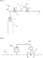
- a first embodiment is represented on [ Fig. 3 ], on which it shows a closer look at the SRD 6.
- the SRD 6 is a bursting disc (BD) 601.
- the BD 601 is a sacrificial part because it has a one-time-use membrane that fails at a predetermined pressure. If the BD 601 is burst, a simple replacement can be executed and maintenance on the PRD 1 becomes simple. In case of overpressure, the BD 601 bursts, letting the fluid flow in the relief fluid circuit 102 to the ESOV 4, said ESOV 4 closing the operational fluid circuit 101, and consequently the whole PRD 1, to avoid any overpressure going to the coupled installation.
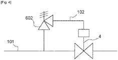
- a second embodiment is represented on [ Fig. 4 ], on which it shows a closer look at the SRD 6.
- the SRD 6 is a safety relief valve (SRV) 602.
- the SRV 602 is reversible, and the system could easily be reset. In case of overpressure, the SRV 602 opens, letting the overpressure fluid go through the relief fluid circuit 102 to the ESOV 4, said ESOV 4 closing the operational fluid circuit 101 to avoid any overpressure going to the coupled installation.
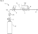
- a third embodiment of the invention is represented on [ Fig. 5 ], on which a residual pressure valve (RPV) 7 is added.
- the RPV 7 is placed upstream of the ESOV 4, but the RPV 7 may as well be placed downstream of the ESOV 4.
- the RPV 7 allows to keep a small amount of pressure stored to help the ESOV 4 engage more quickly.
- a gas filter 13 is also placed on the system, the gas filter 13 filtering out any unwanted particles.
- a fourth embodiment of the invention is represented on [ Fig. 6 ], on which a non-return valve (NRV) 8 is placed downstream of the ESOV 4.
- the NRV 8 allows the fluid to flow in only one direction and may be fitted to ensure that the fluid flows through the circuits in the right direction, where pressure conditions may otherwise cause reversed flow.
- the RPV 7 and the NRV 8 are placed upstream and downstream of the ESOV 4 respectively.
- the position of the RPV 7 and the NRV 8 might vary, i.e. their places might be interchanged, both the RPV 7 and the NRV 8 might be placed upstream of the ESOV 4 or downstream of the ESOV 4.
- the PRD 1 may have a NRV 8, and its position may vary. In addition, the number of non-return valves found in the PRD 1 may be more than one.
- a fifth embodiment of the invention is represented on [ Fig. 7 ], on which a closer look is taken on the emergency shutoff valve.
- the RPV 7 is used as the emergency shutoff valve.
- the RPV 7 will therefore have two roles, and will be used to close the system when the SRD 6 is open.
- a NRV 8 may also be placed downstream of the RPV 7.
- the RPV 7 can be used as an emergency shutoff valve, by connecting the SRD back to the RPV 7 through the relief fluid circuit 102.
- the NRV 8 shown on [ Fig. 7 ] is optional, may be placed somewhere else on the PRD 1 and may not be the only NRV on the system.
- a sixth embodiment of the invention is represented on [ Fig. 8 ], on which the RPV 7 acts as the ESOV 4, and where the RPV 7 comprises a NRV 8.
- This NRV feature might be added as a separate and complementary function.
- a seventh embodiment of the invention is represented on [ Fig. 9 ], on which we can see a close look at the relief fluid circuit 102.
- the SRD is the SRV 602
- the ESOV 4 is the RPV 7.
- a reset valve 9 is placed downstream of the SRV 602.
- the reset valve 9 is used to collect the overpressure at the back of the ESOV when the SRV 602, or more generally the SRD, is open.
- the reset valve is used to easily reopen the system by purging the zone downstream of the SRD and to the back of the ESOV (upstream).
- the emergency shutoff valve 4 and/or the residual pressure valve 7 may use gaskets and/or seals such as O-ring seals, said gaskets and/or seals being prone to leak. These leaks would be minimal but might need consideration. Therefore, the PRD 1 may comprise a bleeding valve 10, as shown on [ Fig. 9 ].
- the bleeding valve 10 allows minor amounts of fluid to be released from the system in case of, for example, leakage from elastomeric rings, to avoid any pressure build-up on the ESOV 4 or the RPV 7 that could hinder the system's core function, especially when the SRD 6 is not open.
- the bleeding valve 10 may also comprise a flap 1001, that would be pushed against the bleeding valve 10 in order to close it when the SRD 6 is open. This flap 1001 would deny the fluid to be released from the bleeding valve in case of pressure surge arising from the SRD 6.
- the flap 1001 may for example be made of polyurethane.
- Fig. 9 presents the SRV 602 as the SRD, but neither the reset valve nor the bleeding valve is limited to be used with a SRV only.
- the SRV 602 is there for the illustration purposes only and the invention is not limited to this type of SRD
- the residual pressure valve 7 comprises a middle chamber 701 in its central part, a front chamber 704, a back chamber 705 being respectively closer to the outlet interface 5 and to the bleeding valve 10, and also comprises a first piston 702.
- An entry connection 1102 connects the PRU 3 and the RPV 7
- a first connection 1103 connects the RPV 7 (downstream) and the SRD 6 (upstream)
- a second connection 1104 connects the SRD 6 (downstream) and the middle chamber 701 (upstream).
- the fluid in the front chamber 704 of the RPV 7 and in the first connection 1103 is smaller than the pressure P L , the fluid would not flow through the second connection 1104 as the SRD 6 is not open. In the contrary, if an overpressure is detected and the SRD 6 is open, the first piston 702 would prevent the fluid flow from going out of the outlet interface 5 as the released pressure would push the first piston 702 toward the outlet interface 5 until it is fully closed.
- the RPV 7 may also comprise a second piston 703, and the middle chamber 701 would be delimited by the first piston 702 and the second piston 703 on each side, and that in the open position of the safety relief device 6, the bleeding valve 10 is closed by the hinged flap 1001 as it is being pushed by the second piston 703 and is extending itself on the bleeding valve 10.
- the first piston 702 When the safety relief device 6 is open, the first piston 702 is pushed by the first springs 7021 as well as the pressure released to the middle chamber, said first piston 702 being pushed towards the outlet interface 5 in order to close the operational fluid circuit 101.
- the second piston 703 when the SRD is open, the second piston 703 is pulled away by the overpressure fluid released by the SRD to allow the flap 1001 to close the bleeding valve 10.
- a second springs 7031 could be used to reopen the bleeding valve 10.
Priority Applications (7)
| Application Number | Priority Date | Filing Date | Title |
|---|---|---|---|
| EP21179536.4A EP4105542A1 (de) | 2021-06-15 | 2021-06-15 | Druckminderungsvorrichtung |
| KR1020247000626A KR20240020276A (ko) | 2021-06-15 | 2022-06-08 | 감압 장치 |
| PCT/EP2022/065496 WO2022263247A1 (en) | 2021-06-15 | 2022-06-08 | Pressure reducing device |
| BR112023026047A BR112023026047A2 (pt) | 2021-06-15 | 2022-06-08 | Dispositivo redutor de pressão |
| AU2022293931A AU2022293931A1 (en) | 2021-06-15 | 2022-06-08 | Pressure reducing device |
| CN202280041153.3A CN117460911A (zh) | 2021-06-15 | 2022-06-08 | 减压装置 |
| CA3220995A CA3220995A1 (en) | 2021-06-15 | 2022-06-08 | Pressure reducing device |
Applications Claiming Priority (1)
| Application Number | Priority Date | Filing Date | Title |
|---|---|---|---|
| EP21179536.4A EP4105542A1 (de) | 2021-06-15 | 2021-06-15 | Druckminderungsvorrichtung |
Publications (1)
| Publication Number | Publication Date |
|---|---|
| EP4105542A1 true EP4105542A1 (de) | 2022-12-21 |
Family
ID=76764810
Family Applications (1)
| Application Number | Title | Priority Date | Filing Date |
|---|---|---|---|
| EP21179536.4A Pending EP4105542A1 (de) | 2021-06-15 | 2021-06-15 | Druckminderungsvorrichtung |
Country Status (7)
| Country | Link |
|---|---|
| EP (1) | EP4105542A1 (de) |
| KR (1) | KR20240020276A (de) |
| CN (1) | CN117460911A (de) |
| AU (1) | AU2022293931A1 (de) |
| BR (1) | BR112023026047A2 (de) |
| CA (1) | CA3220995A1 (de) |
| WO (1) | WO2022263247A1 (de) |
Citations (7)
| Publication number | Priority date | Publication date | Assignee | Title |
|---|---|---|---|---|
| US4188971A (en) * | 1978-04-27 | 1980-02-19 | The United States Of America As Represented By The Secretary Of The Navy | Fluid cutout valve |
| GB2287330A (en) * | 1994-03-08 | 1995-09-13 | Trevor Thomas Jenkins | Pressure-activated safety shut-off valve |
| EP0532402B1 (de) * | 1991-09-13 | 1996-01-10 | Gaz De France (Service National) | Automatische Sperr- und Sicherheitsvorrichtung, insbesondere für Gasentspannungsstationen |
| US5752544A (en) * | 1995-12-01 | 1998-05-19 | Gaz De France | Device for feeding a distribution network with gaseous fluid |
| US20140318642A1 (en) * | 2013-04-25 | 2014-10-30 | Spectron Gas Control Systems GmbH | Safety device for installation in a gas-supply system, in particular, an acetylene-supply system |
| US9328745B2 (en) * | 2012-11-05 | 2016-05-03 | Magna Steyr Fahrzeugtechnik Ag & Co Kg | Pressure storage system and method to operate pressure storage system |
| EP3495713A1 (de) * | 2017-12-06 | 2019-06-12 | Micro Matic A/S | Ventilanordnung |
-
2021
- 2021-06-15 EP EP21179536.4A patent/EP4105542A1/de active Pending
-
2022
- 2022-06-08 AU AU2022293931A patent/AU2022293931A1/en active Pending
- 2022-06-08 WO PCT/EP2022/065496 patent/WO2022263247A1/en active Application Filing
- 2022-06-08 CN CN202280041153.3A patent/CN117460911A/zh active Pending
- 2022-06-08 KR KR1020247000626A patent/KR20240020276A/ko unknown
- 2022-06-08 BR BR112023026047A patent/BR112023026047A2/pt unknown
- 2022-06-08 CA CA3220995A patent/CA3220995A1/en active Pending
Patent Citations (7)
| Publication number | Priority date | Publication date | Assignee | Title |
|---|---|---|---|---|
| US4188971A (en) * | 1978-04-27 | 1980-02-19 | The United States Of America As Represented By The Secretary Of The Navy | Fluid cutout valve |
| EP0532402B1 (de) * | 1991-09-13 | 1996-01-10 | Gaz De France (Service National) | Automatische Sperr- und Sicherheitsvorrichtung, insbesondere für Gasentspannungsstationen |
| GB2287330A (en) * | 1994-03-08 | 1995-09-13 | Trevor Thomas Jenkins | Pressure-activated safety shut-off valve |
| US5752544A (en) * | 1995-12-01 | 1998-05-19 | Gaz De France | Device for feeding a distribution network with gaseous fluid |
| US9328745B2 (en) * | 2012-11-05 | 2016-05-03 | Magna Steyr Fahrzeugtechnik Ag & Co Kg | Pressure storage system and method to operate pressure storage system |
| US20140318642A1 (en) * | 2013-04-25 | 2014-10-30 | Spectron Gas Control Systems GmbH | Safety device for installation in a gas-supply system, in particular, an acetylene-supply system |
| EP3495713A1 (de) * | 2017-12-06 | 2019-06-12 | Micro Matic A/S | Ventilanordnung |
Also Published As
| Publication number | Publication date |
|---|---|
| CN117460911A (zh) | 2024-01-26 |
| KR20240020276A (ko) | 2024-02-14 |
| AU2022293931A1 (en) | 2024-01-25 |
| CA3220995A1 (en) | 2022-12-22 |
| WO2022263247A1 (en) | 2022-12-22 |
| BR112023026047A2 (pt) | 2024-03-05 |
Similar Documents
| Publication | Publication Date | Title |
|---|---|---|
| EP2347158B1 (de) | Ventile mit entfernbaren inneren betätigungsmechanismen | |
| CA2766270C (en) | Methods and apparatus to charge accumulator apparatus | |
| US20100319804A1 (en) | Device for filling and distributing gas and assembly comprising such a device | |
| KR101403189B1 (ko) | 압력 유체 실린더 | |
| US4240463A (en) | Safety valve actuator and pilot system | |
| EP2519752B1 (de) | Vorrichtung zur krafterhöhung eines stellantriebs mit übersteuerungsvorrichtung | |
| EP3112690A1 (de) | Pneumatisch betätigtes hdv abblasventil, das von einem magnetventil gesteuert wird, das wiederum in seiner schliessstellung von einem flussbegrenzenden ventil unterstützt wird | |
| JP2007537538A (ja) | サージ除去装置および方法 | |
| EP0050926B1 (de) | Ventil mit aufweitbarer Schlauchmembrane | |
| EP4105542A1 (de) | Druckminderungsvorrichtung | |
| WO2021056613A1 (zh) | 可快速自动关闭的装置及天然气井口紧急切断装置 | |
| US3621872A (en) | Safety valve | |
| CA2035682C (en) | Safety device and method | |
| CN112823255A (zh) | 用于提供冗余安全切断的紧急关断安全组件 | |
| US3709241A (en) | Fill limiter, check and safety valve | |
| WO2006108770A2 (en) | Pressure regulating device for natural gas | |
| RU16024U1 (ru) | Автомат аварийного закрытия запорной арматуры магистрального газопровода | |
| GB2584318A (en) | Improvements relating to valves for fire suppression systems | |
| CN213874941U (zh) | 一种先导式安全阀在线校验装置 | |
| EP2564099B1 (de) | Steurung von flüssigkeitströmungen | |
| US20230109588A1 (en) | Spring loaded sleeve valve with controlled closing force | |
| CN114321462A (zh) | 压差控制截断泄放装置及压差控制截断系统 | |
| CN114127451A (zh) | 止回阀 | |
| CN116507987A (zh) | 用于阻挡加压气体通过管道的先导操作型阻挡装置,以及用于该阻挡装置的压力调节器 | |
| KR20210059872A (ko) | 보조팽창가스 시스템을 포함하는 컨트롤 밸브용 포지셔너 |
Legal Events
| Date | Code | Title | Description |
|---|---|---|---|
| PUAI | Public reference made under article 153(3) epc to a published international application that has entered the european phase |
Free format text: ORIGINAL CODE: 0009012 |
|
| STAA | Information on the status of an ep patent application or granted ep patent |
Free format text: STATUS: THE APPLICATION HAS BEEN PUBLISHED |
|
| AK | Designated contracting states |
Kind code of ref document: A1 Designated state(s): AL AT BE BG CH CY CZ DE DK EE ES FI FR GB GR HR HU IE IS IT LI LT LU LV MC MK MT NL NO PL PT RO RS SE SI SK SM TR |
|
| STAA | Information on the status of an ep patent application or granted ep patent |
Free format text: STATUS: REQUEST FOR EXAMINATION WAS MADE |
|
| 17P | Request for examination filed |
Effective date: 20230621 |
|
| RBV | Designated contracting states (corrected) |
Designated state(s): AL AT BE BG CH CY CZ DE DK EE ES FI FR GB GR HR HU IE IS IT LI LT LU LV MC MK MT NL NO PL PT RO RS SE SI SK SM TR |