EP4105098B1 - Operation state diagnostic device - Google Patents
Operation state diagnostic device Download PDFInfo
- Publication number
- EP4105098B1 EP4105098B1 EP21753205.0A EP21753205A EP4105098B1 EP 4105098 B1 EP4105098 B1 EP 4105098B1 EP 21753205 A EP21753205 A EP 21753205A EP 4105098 B1 EP4105098 B1 EP 4105098B1
- Authority
- EP
- European Patent Office
- Prior art keywords
- vehicle
- value
- vehicle body
- vertical
- acceleration
- Prior art date
- Legal status (The legal status is an assumption and is not a legal conclusion. Google has not performed a legal analysis and makes no representation as to the accuracy of the status listed.)
- Active
Links
Images







Classifications
-
- G—PHYSICS
- G01—MEASURING; TESTING
- G01M—TESTING STATIC OR DYNAMIC BALANCE OF MACHINES OR STRUCTURES; TESTING OF STRUCTURES OR APPARATUS, NOT OTHERWISE PROVIDED FOR
- G01M17/00—Testing of vehicles
- G01M17/08—Railway vehicles
- G01M17/10—Suspensions, axles or wheels
-
- B—PERFORMING OPERATIONS; TRANSPORTING
- B61—RAILWAYS
- B61F—RAIL VEHICLE SUSPENSIONS, e.g. UNDERFRAMES, BOGIES OR ARRANGEMENTS OF WHEEL AXLES; RAIL VEHICLES FOR USE ON TRACKS OF DIFFERENT WIDTH; PREVENTING DERAILING OF RAIL VEHICLES; WHEEL GUARDS, OBSTRUCTION REMOVERS OR THE LIKE FOR RAIL VEHICLES
- B61F5/00—Constructional details of bogies; Connections between bogies and vehicle underframes; Arrangements or devices for adjusting or allowing self-adjustment of wheel axles or bogies when rounding curves
- B61F5/02—Arrangements permitting limited transverse relative movements between vehicle underframe or bolster and bogie; Connections between underframes and bogies
- B61F5/22—Guiding of the vehicle underframes with respect to the bogies
- B61F5/24—Means for damping or minimising the canting, skewing, pitching, or plunging movements of the underframes
- B61F5/245—Means for damping or minimising the canting, skewing, pitching, or plunging movements of the underframes by active damping, i.e. with means to vary the damping characteristics in accordance with track or vehicle induced reactions, especially in high speed mode
Definitions
- the present disclosure relates to an operation state diagnostic device which diagnoses a shock absorber arranged, for example, between a vehicle body and a bogie of a railway vehicle.
- Patent Literature 1 There is known a vehicle in which shock absorbers are arranged between bogies and a vehicle body in order to increase ride comfort of a railway vehicle.
- Patent Literature 1 there is described a technology of arranging yaw dampers serving as shock absorbers between a vehicle body and bogies of a railway vehicle, to thereby suppress bending vibration of the vehicle body while suppressing vibration of the bogies.
- the shock absorber contributes to an increase in ride comfort of crews and passengers, and hence it is desired to be able to diagnose an abnormality thereof before an operation of the railway vehicle or during the operation thereof.
- Patent Literature 2 there is described a technology of detecting both of vibration of bogies and vibration of wheelsets, to thereby detect a track abnormality and a bogie abnormality based on vibration values of the bogies and vibration values of the wheelsets.
- Patent Literature 3 there is described a technology of vibrating a railway vehicle in a stop state, to thereby diagnose an abnormality.
- Patent Literature 4 there is described a technology of detecting an acceleration in a vertical direction and an acceleration in a pitching direction, and detecting an abnormality of a shock absorber from a phase difference between a vertical translation and a pitching.
- JP 2005 067276 A relates to an apparatus which detects the abnormality of a rail vehicle, specifically by detecting vibration data during traveling/driving of a rail vehicle.
- a vehicle state database is referred during traveling/driving of the vehicle.
- An estimation coefficient adjustment means is used. By adjusting an estimation gain and a vehicle model parameter according to a running status, the estimation precision by the estimation means is improved. Thereby, an incorrect detection is decreased.
- JP 2017 144909 A relates to a method and a device for detecting abnormality of a secondary spring system provided between a body of a railway car and a truck, and more particularly to a method and a device for detecting abnormality of a secondary spring system .
- CN 104 155 968 A discloses a kind of small fault diagnostic method for bullet train suspension system actuator, and particularly relates to the detection and the method for estimation of a closed-loop control system small fault based on a failure message whole step amount residual error.
- An object of one embodiment of the present invention is to provide an operation state diagnostic device capable of increasing an accuracy of determination of an abnormality while suppressing an addition of sensors (measurement means).
- an operation state diagnostic device for a shock absorber arranged between a vehicle body and a bogie of a railway vehicle, the operation state diagnostic device including: a position detection unit configured to obtain a travel position of the railway vehicle to output the travel position; a pressure measurement unit configured to measure a pressure value of pressure loaded on a spring mechanism provided between the vehicle body and the bogie to output the pressure value; a spring mechanism displacement calculation unit configured to calculate a vertical displacement of the spring mechanism through use of the pressure value of the spring mechanism output from the pressure measurement unit to output the vertical displacement; a spring mechanism displacement estimation unit which is arranged on the railway vehicle, and is configured to estimate the vertical displacement of the spring mechanism through use of a railway vehicle model obtained by modeling the railway vehicle, the travel position, and the pressure value of the spring mechanism to output the vertical displacement; and a shock absorber abnormality determination unit configured to determine an abnormality of the shock absorber by comparing a calculation value of the vertical displacement of the spring mechanism output from the spring mechanism displacement calculation unit and an estimation value of
- an operation state diagnostic device for a shock absorber arranged between a vehicle body and a bogie of a railway vehicle
- the operation state diagnostic device including: a vehicle body acceleration measurement unit configured to measure a vertical acceleration of the vehicle body to output the vertical acceleration; a position detection unit configured to obtain a travel position of the railway vehicle to output the travel position; a pressure measurement unit configured to measure a pressure value of pressure loaded on a spring mechanism provided between the vehicle body and the bogie to output the pressure value; a vehicle body acceleration estimation unit which is arranged on the railway vehicle, and is configured to estimate the vertical acceleration of the vehicle body through use of a railway vehicle model obtained by modeling the railway vehicle, the travel position, and the pressure value of the spring mechanism to output the vertical acceleration; and a shock absorber abnormality determination unit configured to determine an abnormality of the shock absorber by comparing a measurement value of the vertical acceleration of the vehicle body output from the vehicle body acceleration measurement unit and an estimation value of the vertical acceleration of the vehicle body output from the vehicle body acceleration estimation
- a left side (one side in a length direction of the train) of the drawings is a front side in a travel direction of the railway vehicle
- a right side (another side in the length direction of the train) of the drawings is a rear side in the travel direction of the railway vehicle.
- the right side of the drawings may be the front side
- the left side of the drawings may be the rear side.
- a railway vehicle 1 (hereinafter referred to as "vehicle 1") includes a vehicle body 2 on which occupants such as passengers and crews are to ride, and a bogie 3A on the front side and a bogie 3B on the rear side, which are provided on a lower side of the vehicle body 2.
- Those two bogies 3A and 3B are arranged apart from each other on the front side (the one side in the length direction of the vehicle body 2 and the left side of Fig. 1 ) and the rear side (the another side in the length direction of the vehicle body 2 and the right side of Fig. 1 ) of the vehicle body 2, respectively.
- the vehicle body 2 of the vehicle 1 is installed on the pair of bogies 3A and 3B.
- Fig. 1 in order to avoid complication of the drawing, one vehicle 1, that is, a train with a single-car formation, is illustrated. However, in general, a train formed by connecting a plurality of vehicles 1 to each other, that is, a train formed of the plurality of vehicles 1, is in operation.
- two wheelsets 6, 6 each formed by providing a wheel 4, 4 on each of both end sides in a length direction of an axle 5, 5 (that is, both end sides in a width direction of the vehicle body 2) are mounted apart from each other in the front-rear direction.
- four wheels 4, 4 are provided to each of the bogies 3A and 3B.
- the vehicle 1 travels along left and right rails R (only one side thereof is illustrated in Fig. 1 ) through rotation of the wheels 4, 4 on the rails R.
- a left-right direction being the width direction of the vehicle body 2 is set with respect to a direction orthogonal to the travel direction as a reference.
- the left-right direction corresponds to the width direction of the vehicle body 2 (axial direction of the axles 5, 5).
- a front side in a front-back direction orthogonal to the drawing sheet is left, and a back side in the front-back direction is right.
- the air springs 7A and 7B are also called as “bolster springs” or “suspension springs,” and correspond to “secondary springs” provided between the vehicle body 2 and the like forming “sprung masses” and the bogies 3A and 3B and the like forming “masses between primary springs and secondary springs.” That is, the air springs 7A and 7B form spring mechanisms provided between the vehicle body 2 and the bogies 3A and 3B.
- the "primary springs” correspond to axle springs (not shown) provided on the bogies 3A and 3B, that is, axle springs provided between the wheels 4, 4 (wheelsets 6, 6) forming "unsprung masses” and bogie frames of the bogies 3A and 3B forming "masses between primary springs and secondary springs.”
- One of the air springs 7A and 7B is provided, for example, on each of the left and right sides of each of the bogies 3A and 3B. That is, two air springs 7A or 7B are provided on one bogie, and four air springs 7A and 7B are provided on one vehicle.
- the dampers 8A and 8B serving as the shock absorbers are arranged between the vehicle body 2 and the bogies 3A and 3B of the vehicle 1.
- Each of the dampers 8A and 8B is, for example, a hydraulic shock absorber formed as a conventional damper (passive damper) having a damping force which changes depending on a stroke speed.
- the dampers 8A and 8B form, together with the air springs 7A and 7B, suspensions which absorb (damp) vibration in a vertical direction between the vehicle body 2 and the bogies 3A and 3B. That is, the dampers 8A and 8B serving as vertical dampers generate damping forces for reducing vibration in the vertical direction of the vehicle body 2 with respect to the bogies 3A and 3B, respectively.
- the dampers 8A and 8B reduce (suppress) the vibration of the vehicle body 2 in the vertical direction.
- the dampers 8A and 8B are arranged, for example, in parallel to the air springs 7A and 7B, respectively.
- One of the dampers 8A and 8B is provided on each of the left and right sides of each of the bogies 3A and 3B, respectively. That is, two dampers 8A or 8B are provided on one bogie, and four dampers 8A and 8B are provided on one vehicle.
- the pressure sensors 9A and 9B are provided to the air springs 7A and 7B, respectively.
- the pressure sensors 9A and 9B detect pressures (internal pressures) of the air springs 7A and 7B, respectively.
- Pressure values measured by the pressure sensors 9A and 9B are used to control, for example, the air springs 7A and 7B.
- the pressure sensors 9A and 9B are connected to a control device (not shown), for example, a control device for controlling the air springs 7A and 7B or a higher-level control device.
- the pressure values measured by the pressure sensors 9A and 9B are used to diagnose operation states of the dampers 8A and 8B as described later.
- the pressure sensors 9A and 9B are connected to a diagnostic device 13 via the control device (not shown) and a communication line 14. That is, signals corresponding to the pressures measured by the pressure sensors 9A and 9B are output to the diagnostic device 13 via the control device (not shown) and the communication line 14.
- the pressure sensors 9A and 9B form a pressure measurement unit configured to measure (detect) the pressure values of pressure loaded on the air springs 7A and 7B, and to output the signals corresponding to those pressure values to the diagnostic device 13.
- a vehicle speed sensor 10 and a position sensor 11 are provided to the vehicle 1.
- the vehicle speed sensor 10 detects a travel speed (vehicle speed) of the vehicle 1.
- the vehicle speed sensor 10 is connected to the control device (not shown), for example, the higher-level control device. As described later, a speed value measured by the speed sensor 10 is used to diagnose the operation states of the dampers 8A and 8B.
- the vehicle speed sensor 10 is connected to the diagnostic device 13 via the control device (not shown) and the communication line 14. That is, the signal corresponding to the vehicle speed measured by the vehicle speed sensor 10 is output to the diagnostic device 13 via the control device (not shown) and the communication line 14.
- the vehicle speed sensor 10 forms a speed measurement unit configured to measure (detect) the speed value of the vehicle 1, and to output the signal corresponding to this speed value to the diagnostic device 13.
- the position sensor 11 obtains a travel position (current position) of the vehicle 1.
- the position sensor 11 includes a receiver which receives signals from navigation satellites of a satellite positioning navigation and timing systems (SPNT) such as the GPS.
- SPNT satellite positioning navigation and timing systems
- the position sensor 11 is connected to the control device (not shown), for example, the higher-level control device. As described later, position information obtained by the position sensor 11 is used to diagnose the operation states of the dampers 8A and 8B.
- the position sensor 11 is connected to the diagnostic device 13 via the control device (not shown) and the communication line 14. That is, the signal corresponding to the position information obtained by the position sensor 11 is output to the diagnostic device 13 via the control device (not shown) and the communication line 14.
- the position sensor 11 forms a position detection unit configured to obtain the position information on the bogies 3A and 3B as the travel position of the vehicle 1, and to output the signal corresponding to this position to the diagnostic device 13.
- the travel position (positions of the bogies 3A and 3B) of the vehicle 1 may be acquired from, in place of the position sensor 11, a railway signal system which is used as, for example, an automatic train stop device, an automatic train control device, or a signal safety device. That is, the position detection unit may be formed of the railway signal system. Similarly, the speed measurement unit may also be formed of the railway signal system when the vehicle speed can be detected by the railway signal system. In those cases, a control device for the railway signal system mounted to the vehicle 1 corresponds to the position detection unit and/or the speed measurement unit.
- a vibration damping device is arranged between a bogie and a vehicle body (for example, Patent Literature 1 to Patent Literature 4). It is intended that the vibration damping device suppresses vibration in the vertical direction or the left-right direction, and there exist, for example, a vibration damping device which uses a damping force adjustable shock absorber (semi-active damper) to switch a damping force in response to a vibration state and a vibration damping device which uses a control actuator (full-active damper) to actively generate a control force, to thereby suppress the vibration.
- Such vibration damping devices contribute to an increase in ride comfort of crews and passengers, and hence it is desired to be able to diagnose an abnormality thereof before an operation of the railway vehicle or during the operation thereof.
- an acceleration (vibration value) of the bogie is detected by an acceleration sensor provided on each of a plurality of bogies, and an acceleration (vibration value) of a wheelset is detected by an acceleration sensor provided on each of a plurality of wheelsets, to thereby detect the track abnormality and the bogie abnormality.
- Patent Literature 3 there is described a technology of vibrating a railway vehicle in a stop state, to thereby diagnose an abnormality of each of devices (a bogie frame, a wheelset, an actuator, and the like) of the vehicle.
- Patent Literature 4 there is described a technology of detecting an acceleration in the vertical direction and an acceleration in a pitching direction, and detecting an abnormality of a shock absorber from a phase difference between a vertical translation and a pitching.
- additional sensors such as a sensor which detects, for example, vibration of a wheelset may be required in addition to existing sensors.
- a system scale may increase.
- an operation state diagnostic device 12 according to the first embodiment can use the existing sensors to highly accurately determine (diagnose) an abnormality without requiring additional sensors. Description is now given of the operation state diagnostic device 12 according to the first embodiment.
- the operation state diagnostic device 12 diagnoses the operation states of the dampers 8A and 8B being the conventional dampers.
- the operation state diagnostic device 12 includes, in addition to the above-mentioned pressure sensors 9A and 9B, vehicle speed sensor 10, and position sensor 11, the diagnostic device 13 serving as a calculation processing device which executes calculation processing for the diagnosis.
- the diagnostic device 13 is provided in the vehicle 1.
- the pressures of the air springs 7A and 7B from the pressure sensors 9A and 9B, the travel speed (vehicle speed) of the vehicle 1 from the vehicle speed sensor 10, and the travel position (current position) of the vehicle 1 from the position sensor 11 are input in real time via the communication line 14.
- the diagnostic device 13 is connected to the higher-level control device (not shown) via the communication line 14.
- vehicle information on the vehicle 1 (that is, vehicle information including the pressures of the air springs 7A and 7B, and the travel speed and the travel position of the vehicle 1) is input to the diagnostic device 13 as higher-level signals via the communication line 14.
- the pressure sensors 9A and 9B, the vehicle speed sensor 10, and the position sensor 11 may be directly connected to the diagnostic device 13.
- the diagnostic device 13 is installed at a position of the vehicle 1 determined in advance (for example, a position substantially at a center of the vehicle body 2).
- the diagnostic device 13 includes, for example, a microcomputer.
- the diagnostic device 13 includes, as a storage unit, a memory 13A formed of a ROM, a RAM, a nonvolatile memory, and the like.
- a processing program for executing a processing flow of Fig. 3 described later that is, a processing program to be used to diagnose the operation states of the dampers 8A and 8B, is stored (recorded).
- a vehicle model such as state equations to be used to calculate a state of the railway vehicle as described in Patent Literature 1 is also stored.
- the pressures of the air springs 7A and 7B and the travel speed and the travel position of the vehicle 1 are stored in real time.
- information (data) for obtaining, from the travel position, a vertical displacement (height position) of the track (railway) at the travel position, that is, relationships between the travel position and the vertical displacements on the left and right tracks corresponding to this travel position are stored as maps (track maps each for each of the left and right wheels). This information (track information) can be rewritten to the latest information when, for example, inspection work, maintenance work, or change work for the tracks has been executed.
- the diagnostic device 13 acquires, in real time, the signals of the pressure values from the pressure sensors 9A and 9B, the signal of the vehicle speed from the vehicle speed sensor 10, and the signal of the travel position from the position sensor 11 during the travel of the vehicle 1. As the vehicle speed and/or the travel position, a signal of the vehicle speed and/or a signal of the travel position from the railway signal system may be used.
- the diagnostic device 13 determines the abnormality of each of the dampers 8A and 8B based on those signals. Specifically, the diagnostic device 13 executes processing of internally executing calculation based on the pressure values of the air springs 7A and 7B and the vehicle speed and the travel position of the vehicle 1, to thereby diagnose the operation states of the dampers 8A and 8B.
- the diagnostic device 13 calculates vertical displacements of the air springs 7A and 7B from the pressure values of the air springs 7A and 7B.
- the diagnostic device 13 uses the "railway vehicle model” to estimate the vertical displacement of each of the air springs 7A and 7B from the "vertical displacement of each of the tracks obtained from the position information" and a "mass change in air spring reaction force calculated from the pressure value of each of the air springs 7A and 7B.” After that, the diagnostic device 13 compares the calculation value and the estimation value of the vertical displacement of each of the air springs 7A and 7B with each other, to thereby determine the abnormality of each of the dampers 8A and 8B.
- the vehicle model of the vehicle 1 is used to calculate the displacement of each of the air springs 7A and 7B as the estimation value (displacement estimation value) based on the travel speed and the current position of the vehicle 1 and the pressure sensor value of each of the air springs 7A and 7B delivered to the various devices included in the vehicle 1.
- the displacement of each of the air springs 7A and 7B is calculated as the calculation value (displacement calculation value) from the pressure sensor value, a pressure receiving area, and a spring constant of each of the air springs 7A and 7B.
- the estimation value and the calculation value are compared with each other, to thereby determine the abnormality of each of the dampers 8A and 8B.
- the diagnostic device 13 includes a reference pressure output unit 15, a subtraction unit 16, a spring displacement calculation unit 17 which forms a spring mechanism displacement calculation unit, a spring reaction force calculation unit 18, a mass change calculation unit 19, a track vertical displacement calculation unit 20 for a front axle position, a delay time calculation unit 21, a track vertical displacement calculation unit 22 for a rear axle position, a spring displacement estimation unit 23 serving as a spring mechanism displacement estimation unit, and a damper abnormality determination unit 24 serving as a shock absorber abnormality determination unit.
- the reference pressure output unit 15 outputs, to the subtraction unit 16, a reference pressure P0 [Pa] for each of the air springs 7A and 7B stored in advance in the memory 13A.
- a reference pressure P0 [Pa] for each of the air springs 7A and 7B stored in advance in the memory 13A.
- the pressure of each of the air springs 7A and 7B (for example, the pressure of each of the four air springs 7A and 7B) is input from each of the pressure sensors 9A and 9B, and the reference pressure (for example, the reference pressure for each of the four air springs 7A and 7B) is input from the reference pressure output unit 15.
- the subtraction unit 16 subtracts the reference pressure P0 from the pressure P [Pa] (that is, the pressure P in real time) of each of the air springs 7A and 7B measured (detected) by each of the pressure sensors 9A and 9B, to thereby obtain a difference pressure ⁇ P with respect to the reference pressure P0 being the reference value. That is, the subtraction unit 16 executes calculation given by Expression 1.
- P ⁇ P 0 ⁇ P
- the subtraction unit 16 outputs the calculated difference pressure ⁇ P (for example, the difference pressure ⁇ P of each of the four air springs 7A and 7B) to the spring displacement calculation unit 17 and the spring reaction force calculation unit 18.
- the difference pressure ⁇ P is input from the subtraction unit 16.
- the spring displacement calculation unit 17 uses the pressure value (more specifically, the difference pressure ⁇ P) of each of the air springs 7A and 7B output from each of the pressure sensors 9A and 9B to calculate the vertical displacement of each of the air springs 7A and 7B, and outputs the calculation value to the damper abnormality determination unit 24.
- the spring displacement calculation unit 17 outputs, to the damper abnormality determination unit 24, the calculated air spring displacement ⁇ X (for example, the air spring displacement ⁇ X of each of the four air springs 7A and 7B) as the calculation value of the vertical displacement of each of the air springs 7A and 7B.
- the difference pressure ⁇ P is input from the subtraction unit 16.
- the spring reaction force calculation unit 18 uses the pressure value (more specifically, the difference pressure ⁇ P) of each of the air springs 7A and 7B output from each of the pressure sensors 9A and 9B to calculate the reaction force of each of the air springs 7A and 7B in the vertical direction, and outputs the calculation value to the mass change calculation unit 19.
- the spring reaction force calculation unit 18 outputs, to the mass change calculation unit 19, the calculated air spring reaction force ⁇ F (for example, the air spring reaction force ⁇ F of each of the four air springs 7A and 7B) as first information relating to the pressure value P of each of the air springs 7A and 7B.
- the air spring reaction force ⁇ F is input from the spring reaction force calculation unit 18.
- the mass change calculation unit 19 uses the first information (air spring reaction force ⁇ F) relating to the pressure value P of each of the air springs 7A and 7B output from the spring reaction force calculation unit 18 to calculate a mass change ⁇ M, and outputs the calculation value to the spring displacement estimation unit 23.
- the mass change calculation unit 19 outputs, to the spring displacement estimation unit 23, the calculated mass change ⁇ M (for example, the mass change ⁇ M of each of the four air springs 7A and 7B) as second information relating to the pressure value P of each of the air springs 7A and 7B.
- ⁇ M for example, the mass change ⁇ M of each of the four air springs 7A and 7B
- the track vertical displacement calculation unit 20 obtains, from the current position L of the vehicle 1, the vertical displacements of the tracks at this position.
- the track vertical displacement calculation unit 20 obtains vertical displacements Sf of the tracks (left front track vertical displacement Sfl and right front track vertical displacement Sfr) at a front axle position (for example, a position of the bogie 3A on the front side in the travel direction) from the current position L of the vehicle 1 based on the track maps (track information) for the left and right wheels (wheels 4) stored in the memory 13A of the diagnostic device 13.
- the track vertical displacement calculation unit 20 outputs the obtained vertical displacements Sf (Sfl and Sfr) of the tracks at the front axle position to the track vertical displacement calculation unit 22 which calculates vertical displacements Sr (left rear track vertical displacement Srl and the right rear track vertical displacement Srr) of the tracks at a rear axle position (for example, the position of the bogie 3B on the rear side in the travel direction). Moreover, the track vertical displacement calculation unit 20 outputs the obtained vertical displacements Sf (Sfl and Sfr) of the tracks at the front axle position to the spring displacement estimation unit 23.
- the track vertical displacement calculation unit 20 when a railroad line on which the vehicle 1 travels is a single line, the track vertical displacement calculation unit 20 can read the data (information) as it is.
- the track vertical displacement calculation unit 20 differentiate the current position L to calculate the travel direction of the electric railcar, and discriminate track information on an inbound line and track information on outbound line from each other based on the travel direction. That is, it is preferred that, in the memory 13A, the track information on the inbound line and the track information on the outbound line be stored, and the track information corresponding to the travel direction at the time be used.
- a reason for this is that the tracks for the vehicle 1 are not completely the same between the inbound line and the outbound line.
- a position and structure of a branch may be different between the inbound line and the outbound line.
- a train travels on, for example, a passing siding or a main line of the same inbound line depending on the type of the train, and hence the train may be discriminated between a local train and a superior train (rapid, express, semi-express, and limited express) based on the position information and the speed, and track information corresponding to this discrimination may be stored in the memory 13A.
- the travel speed V [m/s] (that is, the travel speed V in real time) of the vehicle 1 measured by the vehicle speed sensor 10 is input.
- the delay time calculation unit 21 obtains a delay time ⁇ between the front axle position and the rear axle position from the travel speed V and a distance between axles D [m] of the vehicle 1 (for example, a distance between the bogie 3A on the front side and the bogie 3B on the rear side). That is, the delay time calculation unit 21 divides the distance between axles D [m] of the vehicle 1 by the travel speed V, to thereby obtain the delay time ⁇ .
- the delay time calculation unit 21 outputs the obtained delay time ⁇ to the track vertical displacement calculation unit 22 for the rear axle position.
- the vertical displacements Sf (Sfl and Sfr) of the tracks at the front axle position are input from the track vertical displacement calculation unit 20 for the front axle position, and the delay time ⁇ is input from the delay time calculation unit 21.
- the track vertical displacement calculation unit 22 for the rear axle position calculates vertical displacements Sr (Srl and Srr) of the tracks at the rear axle position from the vertical displacements Sf (Sfl and Sfr) of the tracks at the front axle position and the delay time ⁇ .
- the track vertical displacement calculation unit 22 outputs the calculated vertical displacements Sr (Srl and Srr) of the tracks at the rear axle position to the spring displacement estimation unit 23.
- the spring displacement estimation unit 23 is arranged on the vehicle 1 together with the spring displacement calculation unit 17, the damper abnormality determination unit 24, and the like.
- the "mass changes ⁇ M of the vehicle body 2" are input from the mass change calculation unit 19
- the “vertical displacements Sf (Sfl and Sfr) of the tracks at the front axle position” are input from the track vertical displacement calculation unit 20
- the “vertical displacements Sr (Srl and Srr) of the tracks at the rear axle position” are input from the track vertical displacement calculation unit 22.
- the spring displacement estimation unit 23 receives the mass changes ⁇ M of the vehicle body 2, the vertical displacements Sf (Sfl and Sfr) of the tracks at the front axle position, and the vertical displacements Sr (Srl and Srr) of the tracks at the rear axle position as inputs, and uses the vehicle model to estimate the vertical displacements of the air springs 7A and 7B through the calculation.
- the spring displacement estimation unit 23 outputs those estimation values to the damper abnormality determination unit 24 as the air spring displacement estimation values ⁇ Xc (for example, the air spring displacement estimation values ⁇ Xc of the four air springs 7A and 7B).
- the spring displacement estimation unit 23 uses the "railway vehicle model obtained by modeling the vehicle 1," the "position information output from the position sensor 11 (more specifically, the vertical displacements Sf and Sr of the tracks obtained from the position information),” and the “pressure values P (more specifically, the mass changes ⁇ M calculated from the pressure values P) of the air springs 7A and 7B" to estimate the vertical displacements of the air springs 7A and 7B, and outputs the vertical displacements to the damper abnormality determination unit 24.
- the spring displacement estimation unit 23 estimates the vertical displacements of the air springs 7A and 7B through the calculation from the "railway vehicle model," the “vertical displacements Sf and Sr of the tracks obtained from the speed value of the vehicle 1 output from the vehicle speed sensor 10 and the position information," and the “second information (mass changes ⁇ M) relating to the pressure values P.”
- the spring displacement estimation unit 23 outputs, to the damper abnormality determination unit 24, the estimated vertical displacements of the air springs 7A and 7B, that is, the air spring displacement estimation values ⁇ Xc being the estimation values of the vertical displacements of the air springs 7A and 7B.
- the "vehicle model" as described in Patent Literature 1 may be used as the railway vehicle model. That is, the spring displacement estimation unit 23 can use the railway model (state equations) as described in paragraph [0036] and the subsequent paragraphs and Fig. 3 of the drawings of Patent Literature 1 to estimate the vertical displacements of the air springs 7A and 7B (to calculate the air spring displacement estimation values ⁇ Xc). The spring displacement estimation unit 23 may use a railway vehicle model (state equations) other than the model as described in Patent Literature 1.
- a vehicle model (state equations) capable of more accurately obtaining the estimation values of the vertical displacements of the air springs 7A and 7B, that is, a vehicle model (state equations) more accurately corresponding to the structure of the vehicle 1, may be used.
- the air spring displacements ⁇ X are input from the spring displacement calculation unit 17, and the air spring displacement estimation values ⁇ Xc are input from the spring displacement estimation unit 23.
- the damper abnormality determination unit 24 compares each of the air spring displacements ⁇ X and each of the air spring displacement estimation values ⁇ Xc with each other, to thereby determine whether each of the dampers 8A and 8B is normal or abnormal.
- the damper abnormality determination unit 24 compares each of the air spring displacements ⁇ X which are output from the spring displacement calculation unit 17, and are the calculation values of the vertical displacements of the air springs 7A and 7B, and each of the air spring displacement estimation values ⁇ Xc which are output from the spring displacement estimation unit 23, and are the estimation values of the vertical displacements of the air springs 7A and 7B with each other, to thereby determine the abnormality.
- the damper abnormality determination unit 24 can determine that each of the dampers 8A and 8B is abnormal, for example, when a difference value between the air spring displacement ⁇ X and the air spring displacement estimation value ⁇ Xc is equal to or larger than a threshold value X1 set in advance.
- the threshold value X1 is a threshold value which serves as a determination criterion for determining whether each of the dampers 8A and 8B is normal or abnormal, and is stored in advance in the memory 13A.
- the threshold value X1 can be obtained in advance thorough, for example, calculation, experiments, simulation, or the like, and is set as a value enabling accurate determination.
- the damper abnormality determination unit 24 outputs (notifies) a result of determination of whether or not each of the dampers 8A and 8B is normal, that is, a vertical damper abnormality detection result, to the higher-level control device as diagnostic information of the diagnostic device 13.
- the higher-level control device can acquire the vertical damper abnormality detection result (whether or not each of the dampers 8A and 8B is normal).
- the higher-level control device displays a warning on a monitor provided in an operation room of the vehicle 1 or the like, to thereby notify an operator of the abnormality.
- the vehicle 1 and the operation state diagnostic device 12 mounted to the vehicle 1 in the first embodiment have the above-mentioned configuration. Next, description is given of an operation thereof.
- the vehicle 1 travels toward, for example, the left side of Fig. 1 along the rails R (tracks).
- vibration such as roll (lateral oscillation) and pitch (oscillation in the front-rear direction) occurs during the travel of the vehicle 1
- the dampers 8A and 8B generate damping forces for reducing the vibration in the vertical direction at this time.
- the vibration of the vehicle body 2 in the vertical direction can be reduced (suppressed).
- the vehicle information on the vehicle 1, that is, the pressure values P of the air springs 7A and 7B and the current position L and the travel speed V of the vehicle 1 is input as the higher-level signals from the higher-level control device to the diagnostic device 13 via the communication line 14 during the travel of the vehicle 1.
- the diagnostic device 13 diagnoses the operation states of the dampers 8A and 8B based on the pressure values P, the current position L, and the travel speed V which are acquired in real time. That is, the diagnostic device 13 determines the abnormality of the dampers 8A and 8B during the travel of the vehicle 1.
- the flowchart of Fig. 3 shows diagnostic processing (determination processing for the abnormality) executed in the diagnostic device 13.
- the processing of Fig. 3 is repeatedly executed at a predetermined control cycle (for example, every 10 msec) after the diagnostic device 13 is activated.
- the diagnostic device 13 acquires the information from the higher-level signals in S1. That is, in S1, the diagnostic device 13 acquires, from the higher-level control device (not shown) via the communication line 14, the vehicle information on the vehicle 1, specifically, the position information (current position L) on the vehicle 1, the speed value (travel speed V) of the vehicle 1, and the pressure values P being the internal pressures of the air springs 7A and 7B.
- the diagnostic device 13 obtains the "vertical displacements Sf (Sfl and Sfr) of the tracks at the front axle position," the “vertical displacements Sr (Srl and Srr) of the tracks at the rear axle position,” and the “mass changes ⁇ M" from the vehicle information (the current position L, the travel speed V, and the pressure values P) acquired in S1, and calculates the air spring displacement estimation values ⁇ Xc based on the railway vehicle model.
- the diagnostic device 13 calculates the air spring displacements ⁇ X from the vehicle information (pressure values P) acquired in S1.
- the diagnostic device 13 determines whether or not each of the dampers 8A and 8B is normal. In this case, in S4, the diagnostic device 13 compares each of the air spring displacement estimation values ⁇ Xc calculated in S2 and each of the air spring displacements ⁇ X calculated in S3 with each other. That is, in S4, the diagnostic device 13 determines whether or not, for example, the difference value between each of the air spring displacement estimation values ⁇ Xc and each of the air spring displacements ⁇ X is equal to or larger than the threshold value X1.
- the diagnostic device 13 determines that each of the damper 8A and 8B is normal, and the process proceeds to S6.
- S6 a signal indicating that "the dampers are normal” is output (notified) as the diagnostic information from the damper abnormality determination unit 24 to the higher-level control device, and the process ends (returns). That is, the process returns from "END" to "START", and the processing steps subsequent to S1 are repeated.
- S7 the diagnostic device 13 determines that any of the dampers 8A and 8B is (are) abnormal, and the process proceeds to S8.
- a signal indicating that "the damper(s) is (are) abnormal” is output (notified) as the diagnostic information from the damper abnormality determination unit 24 to the higher-level control device, and the process ends (returns).
- the notification indicating that "the dampers are normal” in S6 may be combined with a notification made during the operation, or may be omitted. That is, the damper abnormality determination unit 24 may be configured to output, as the diagnostic information, the signal indicating that "damper(s) is (are) abnormal” to the higher-level control device only when the damper abnormality determination unit 24 determines that any of the dampers 8A and 8B is (are) abnormal.
- the comparison may always be made in real time, or average values within a period set in advance (specified period) may be compared with each other. Further, the damper abnormality determination unit 24 may determine that each of the dampers 8A and 8B is abnormal when an integrated value of the difference between the air spring displacement ⁇ X and the air spring displacement estimation value ⁇ Xc is equal to or larger than a specified value. That is, the numerical value processing relating to the abnormality determination (diagnosis for the operation state) is not limited to the above-mentioned processing.
- the difference value between the air spring displacement estimation value ⁇ Xc and the air spring displacement ⁇ X of each of all of the air springs 7A and 7B is determined to be equal to or larger than the threshold value X1 in S4.
- the tracks may be determined to be abnormal.
- a processing step of making this determination may be added after the processing step of S4 of Fig. 3 .
- the damper abnormality determination unit 24 may, for example, increase a section of the travel railroad line for the abnormality determination, may determine that the track is abnormal when the abnormality occurs (the difference value is equal to or larger than the threshold value X1) in only a specific section (short section) of the travel railroad line, and may determine that each of the dampers 8A and 8B is abnormal when the abnormality occurs (the difference value is equal to or larger than the threshold value X1) in the entire travel railroad line. That is, the track abnormality and the damper abnormality may be discriminated from each other.
- the abnormality determination (operation state diagnosis) of the dampers 8A and 8B can be made highly accurately in real time based on the information always flowing through the vehicle 1 as the higher-level signals during the travel of the vehicle 1.
- the "air spring displacement ⁇ X being the calculation value of the vertical displacement of each of the air springs 7A and 7B” and the “air spring displacement estimation value ⁇ Xc being the estimation value of the vertical displacement of each of the air springs 7A and 7B” are compared with each other, to thereby determine the abnormality.
- the spring displacement calculation unit 17 can use the pressure value P measured by each of the existing pressure sensors 9A and 9B to calculate the air spring displacement ⁇ X.
- the spring displacement estimation unit 23 can use the pressure value P measured by each of the existing pressure sensors 9A and 9B and the position information acquired by the existing position sensor 11 to estimate the air spring displacement estimation value ⁇ Xc.
- the spring displacement estimation unit 23 can use the railway vehicle model to estimate the air spring displacement estimation value ⁇ Xc from the information on the tracks (the vertical displacements Sf and Sr of the tracks) at the position obtained from the position information, and hence the accuracy of the estimation can be increased. As a result, the accuracy of the determination of the abnormality can be increased while suppressing requirement for additional sensors.
- the spring displacement estimation unit 23 estimates the air spring displacement estimation value ⁇ Xc from the "railway vehicle model," "each of the vertical displacements Sf and Sr of the tracks obtained from the speed value output from the vehicle speed sensor 10 and the position information acquired from the existing position sensor 11," and "each of the mass changes ⁇ M of the vehicle body 2 being the information relating to the pressure value P.”
- the spring displacement estimation unit 23 can use each of the vertical displacements Sf (Sfl and Sfr) of the tracks at the position corresponding to the axle on the front side (the bogie 3A on the front side) in the travel direction and each of the vertical displacements Sr (Srl and Srr) of the tracks at the position corresponding to the axle on the rear side (the bogie 3B on the rear side) in the travel direction to estimate each of the air spring displacement estimation values ⁇ Xc.
- the estimation accuracy of the spring displacement estimation unit 23 can be further increased.
- the configuration in which the speed value (travel speed V) output from the vehicle speed sensor 10 is used to calculate the vertical displacements Sr (Srl and Srr) of the tracks at the position corresponding to the axle on the rear side (bogie 3B on the rear side) in the travel direction.
- the configuration is not limited to this example.
- the vehicle speed sensor 10 may be omitted, and the speed value (travel speed V) calculated from the position information (current position L) of the position sensor 11 may be used to calculate the vertical displacements Sr (Srl and Srr) of the tracks at the position corresponding to the axle on the rear side (bogie 3B on the rear side) in the travel direction.
- the spring mechanism displacement estimation unit may estimate the vertical displacement of the spring mechanism from the "railway vehicle model,” the “vertical displacement of the track obtained from the speed value of the railway vehicle calculated from the position information and the position information,” and the “information relating to the pressure value.” Also in this case, the spring mechanism displacement estimation unit can use the vertical displacements of the tracks at the position corresponding to the axle on the front side in the travel direction and the vertical displacements of the tracks at the position corresponding to the axle on the rear side in the travel direction to estimate the vertical displacements of the spring mechanisms. Thus, also in this case, the estimation accuracy of the spring mechanism displacement estimation unit can be further increased.
- the configuration has been given of, as an example, the case of the configuration of using the position information (current position L) and the speed value (travel speed V) to obtain the vertical displacements Sf (Sfl and Sfr) of the tracks at the position corresponding to the axle on the front side (the bogie 3A on the front side) in the travel direction and the vertical displacements Sr (Srl and Srr) of the tracks at the position corresponding to the axle on the rear side (the bogie 3B on the rear side) in the travel direction.
- the configuration is not limited to this example.
- the vertical displacements of the tracks may be obtained without using the speed value.
- the vertical displacements of the tracks at the position corresponding to the axle on the front side (the bogie on the front side) in the travel direction and the vertical displacements of the tracks at the position corresponding to the axle on the rear side (the bogie on the rear side) in the travel direction may be obtained from the current position (position information) of the railway vehicle, the track information (track maps) on the railroad line on which the railway vehicle is traveling, and dimensions of the railway vehicle.
- the diagnostic device 13 which executes the calculation processing for determining the abnormality of the dampers 8A and 8B is provided independently of the higher-level control device, but the diagnostic device 13 may be built into the higher-level control device. That is, the abnormality determination for the shock absorbers may have a configuration including a dedicated arithmetic processing device (microcomputer) which makes this determination or a configuration in which this determination is made by an arithmetic processing device (microcomputer) which executes other control processing.
- microcomputer dedicated arithmetic processing device
- the abnormality determination can always be made in real time by the diagnostic device 13 during the travel of the vehicle 1.
- the error of the calculation function (estimation function) based on the railway vehicle model of the diagnostic device 13 may increase (the accuracy of the air spring displacement estimation values ⁇ Xc may decrease) depending on the travel speed V of the vehicle 1 and the track condition (current position L).
- the abnormality determination (operation state diagnosis) may be made when the vehicle 1 is traveling in a travel section (between L1 and L2) set in advance at a travel speed (between V1 and V2) set in advance.
- the diagnostic device 13 uses the air spring displacement estimation value ⁇ Xc at the time when the position information (current position L) is within the range (L1 ⁇ L ⁇ L2) set in advance, and the speed value (travel speed V) is within the range (V1 ⁇ V ⁇ V2) set in advance, to thereby diagnose the operation state of each of the dampers 8A and 8B.
- processing steps of S21 and S22 are added between S1 and S2 of Fig. 3 in the first embodiment. That is, in the first modification example, as illustrated in Fig. 4 , the processing steps of S21 and S22 are executed between S1 and S2.
- the section and the travel speed for the abnormality determination are set.
- the abnormality determination can be stopped under a state in which other vehicles are congested before and after the vehicle 1 and the travel speed V of the vehicle 1 is thus lower than a normal speed in morning or evening commuting hours, for example.
- the air spring displacement estimation values ⁇ Xc in a section in which the tracks are extremely unstable (place inappropriate for the abnormality determination) such as sections before and after a turnout can be excluded, and the air spring displacement estimation values ⁇ Xc in a section in which the tracks are extremely stable (place appropriate for the abnormality determination) such as a straight and horizontal section can be employed.
- the accuracy of the abnormality determination can be increased. That is, according to the first modification example described above, the operation states of the dampers 8A and 8B can be diagnosed by using the air spring displacement estimation values ⁇ Xc at the time when the position information is within the range defined in advance.
- the operation states of the dampers 8A and 8B can be diagnosed by using the air spring displacement estimation values ⁇ Xc in the travel section in which the tracks are stable such as a straight section.
- the accuracy of the determination of the abnormality can be increased also in this respect.
- Any one of S21 and S22 may be omitted.
- the abnormality determination can always be made in real time by the diagnostic device 13 during the travel of the vehicle 1.
- the error may increase depending on the travel condition of the vehicle 1 and the load condition of the vehicle body 2.
- the abnormality determination (operation state diagnosis) may be made during a period (between t1 and t2) set in advance as in a second modification example illustrated in Fig. 5 . That is, in the second modification example, the diagnostic device 13 uses the air spring displacement estimation value ⁇ Xc at the time when the current time is within the range (t1 ⁇ t ⁇ t2) defined in advance, to thereby diagnose the operation state of each of the dampers 8A and 8B.
- processing steps of S31 and S32 are added between S1 and S2 of Fig.
- the time for the abnormality determination is set.
- the abnormality determination can be made under a condition that the travel condition of the vehicle 1 is relatively constant, for example, early in the morning, late at night, or in the daytime.
- the accuracy of the abnormality determination can be increased. That is, according to the second modification example described above, the operation states of the dampers 8A and 8B can be diagnosed by using the air spring displacement estimation values ⁇ Xc at the time when the current time is within the range defined in advance.
- the operation states of the dampers 8A and 8B can be diagnosed by using the air spring displacement estimation values ⁇ Xc at the time when the travel condition of the vehicle 1 is relatively constant, for example, early in the morning, late at night, or in the daytime.
- the accuracy of the determination of the abnormality can be increased also in this respect.
- Fig. 6 shows a third modification example.
- the third modification example is a combination of the first modification example and the second modification example. That is, in the third modification example, the abnormality determination (operation state diagnosis) may be made when the vehicle 1 is traveling in the travel section (between L1 and L2) set in advance at the travel speed (between V1 and V2) set in advance, and the current time is within the time (between t1 and t2) set in advance. As a result, the accuracy of the abnormality determination can be further increased.
- the abnormality determination is made independently of the values of the pressures (internal pressures) of the air springs 7A and 7B.
- the vehicle 1 usually adjusts the internal pressures of the air springs 7A and 7B in response to the number of crews and passengers, to thereby maintain a vehicle height to be constant.
- the abnormality determination may be made when the pressures of the air springs 7A and 7B are within a range (between P1 and P2) set in advance.
- the diagnostic device 13 uses the air spring displacement estimation value ⁇ Xc at the time when the pressure P of each of the air springs 7A and 7B is within the range (P1 ⁇ P ⁇ P2) set in advance, to thereby diagnose the operation state of each of the dampers 8A and 8B.
- a processing step of S41 is added after the processing step of S32 in the third modification example illustrated in Fig. 6 . That is, in the fourth modification example, as illustrated in Fig. 7 , the processing step of S41 is executed between S32 and S2.
- the abnormality determination may be made when the vehicle 1 is traveling on the outbound line.
- the travel direction of the vehicle 1 can be determined from, for example, the position information.
- the operation states of the dampers 8A and 8B can be diagnosed through use of the vertical displacements of the tracks corresponding to the travel direction of the vehicle 1 determined from the position information.
- the threshold values are not required to be changed, and, for example, the threshold values for the time, the speed, and the like may be the same.
- the travel direction corresponding to the travel of the railway vehicle such as the inner line and the outer line may be selected.
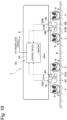
- Fig. 10 to Fig. 13 show a second embodiment of the present invention.
- a feature of the second embodiment is a configuration in which the shock absorbers between the bogie and the wheels are damping force adjustable dampers (semi-active dampers), and the diagnosis (abnormality determination processing) for the operation state is executed by a control device which controls damping forces of the damping force adjustable dampers.
- the same components as those in the first embodiment are denoted by the same reference symbols, and description thereof is omitted.
- Dampers 31A to 31D serving as the shock absorbers are arranged between the vehicle body 2 and the bogies 3A and 3B of the vehicle 1.
- Each of the dampers 31A to 31D is the damping force adjustable damper (semi-active damper) capable of adjusting the damping force, and suppresses the vibration of the bogies 3A and 3B.
- the dampers 31A to 31D include control valves 37A to 37D such as solenoid valves, respectively.
- a damping characteristic of each of the dampers 31A to 31D can continuously be adjusted from a hard characteristic to a soft characteristic by adjusting a valve opening pressure of each of the control valves 37A to 37D through supply of electric power (drive current) from a control device 34.
- each of the dampers 31A to 31D is not limited to the damper which continuously adjusts the damping characteristic, and may be a damper which can adjust the damping characteristic at two stages or a plurality of stages.
- each of the dampers 31A to 31D may be a damping force adjustable shock absorber (for example, a shock absorber enclosing functional fluid such as electrorheological fluid or magnetorheological fluid) which adjusts the damping force in response to a voltage or a current. That is, as each of the dampers 31A to 31D, various types of damping force adjustable shock absorbers which can adjust (increase and decrease) the damping force at the same piston speed can be used. As illustrated in Fig.
- dampers 31A to 31D are arranged on one of the bogies 3A and 3B, and four dampers 31A to 31D are arranged on one vehicle 1 (two bogies 3A and 3B). That is, the dampers 31A to 31D serving as vertical dampers are arranged in parallel with air springs 7A to 7D, respectively, as in the dampers 8A and 8B in the first embodiment.
- a total of four acceleration sensors 32A to 32D each of which measures, at a position thereof, an acceleration (vibration) in the vertical direction of the vehicle body 2 are provided at four corners of the vehicle body 2, that is, four positions apart from each other in the front-rear direction and the left-right direction of the vehicle body 2.
- the acceleration sensors 32A to 32D are sensors (behavior sensors) which are mounted to the plurality of different locations of the vehicle 1, and detect a behavior (more specifically, a vibration state of the vehicle body 2) of the vehicle 1.
- various types of acceleration sensors such as a sensor of the piezoelectric type, the servo type, or the piezoresistive type or another analog acceleration sensor, can be used.
- the accelerations (vertical accelerations) measured by the acceleration sensors 32A to 32D are used to control the dampers 31A to 31D and to diagnose the operation states of the dampers 31A to 31D.
- the acceleration sensors 32A to 32D are connected to the control device 34.
- the acceleration sensors 32A to 32D form a vehicle body acceleration measurement unit configured to measure the vertical accelerations of the vehicle body 2, and to output signals corresponding to the accelerations to the control device 34.
- the sensor arrangement on the vehicle body 2 is not limited to the form in which the acceleration sensors 32A to 32D are arranged on the front left side, the front right side, the rear left side, and the rear right side of the vehicle body 2, and may be any form such as a form in which the acceleration sensors 32A to 32D are arranged at a center of a front portion, on a left side of a center portion, on a right side of the center portion, and at a center of a rear portion of the vehicle body 2.
- the number of the acceleration sensors 32A to 32D is not limited to four, and may freely be selected in accordance with a purpose of the measurement and control. For example, two, three, or five or more acceleration sensors may be provided on the vehicle body 2.
- control device 34 which variably controls (adjusts) the damping force of each of the dampers 31A to 31D.
- the control device 34 is installed at a position of the vehicle 1 (for example, a position substantially at the center of the vehicle body 2) determined in advance.
- the control device 34 includes, for example, a microcomputer and a drive circuit.
- An input side of the control device 34 is connected to the acceleration sensors 32A to 32D.
- An output side of the control device 34 is connected to the dampers 31A to 31D (more specifically, the control valves 37A to 37D).
- the control device 34 includes, as a storage unit, a memory 34A formed of a ROM, a RAM, a nonvolatile memory, and the like.
- a processing program for controlling the damping forces of the dampers 31A to 31D is stored.
- control device 34 is connected to the higher-level control device (not shown) via the communication line 14.
- vehicle information on the vehicle 1 for example, the current position L and the travel speed V of the vehicle
- the acceleration sensors 32A to 32D may be connected to the higher-level control device, and the vertical accelerations may also be input as higher-level signals to the control device 34.
- the control device 34 internally executes calculation based on the sensor signals acquired from the acceleration sensors 32A to 32D and the higher-level signals acquired via the communication line 14, to thereby output a drive current serving as a command signal to each of the dampers 31A to 31D (more specifically, each of the control valves 37A to 37D). That is, the control device 34 calculates the drive current corresponding to the damping force to be generated in each of the dampers 31A to 31D in accordance with a predetermined control law (damping control logic) while reading, for example, the detection signals from the acceleration sensors 32A to 32D after each sampling time.
- a predetermined control law damping control logic
- the control device 34 outputs the drive current to each of the control valves 37A to 37D, to thereby variably control the force to be generated by each of the dampers 31A to 31D.
- the control law for each of the dampers 31A to 31D for example, the skyhook control law, the LQG control law, or the H ⁇ control law may be used.
- the operation state diagnostic device 33 diagnoses the operation states of the dampers 31A to 31D being the semi-active dampers.
- the operation state diagnostic device 33 includes pressure sensors 9A to 9D, the vehicle speed sensor 10, the position sensor 11, the acceleration sensors 32A to 32D, and the control device 34 serving as an arithmetic processing device which executes arithmetic processing for the diagnosis.
- the control device 34 serves as not only a control device which executes arithmetic processing for the control of the damping forces of the dampers 31A to 31D, but also a diagnostic device which executes the arithmetic processing for the diagnosis (abnormality determination) for the operation states of the dampers 31A to 31D.
- a processing program for executing a processing flow illustrated in Fig. 13 described later that is, a processing program to be used to diagnose the operation states of the dampers 31A to 31D, is also stored.
- the reference values, the determination values, the vehicle model, the track information (track map of each of the left and right wheels), and the like to be used to diagnose the operation states are stored.
- the pressures of the air springs 7A to 7D from the pressure sensors 9A to 9D, the travel speed (vehicle speed) of the vehicle 1 from the vehicle speed sensor 10, and the travel position (current position) of the vehicle 1 from the position sensor 11 are input via the communication line 14 in real time.
- the vertical accelerations of the vehicle body 2 from the acceleration sensors 32A to 32D are also input in real time. That is, the control device 34 acquires, in real time, the signals of the pressure values from the pressure sensors 9A to 9D, the signal of the vehicle speed from the vehicle speed sensor 10, the signal of the travel position from the position sensor 11, and the signals of the vertical accelerations from the acceleration sensors 32A to 32D during the travel of the vehicle 1.
- the control device 34 determines the abnormality of each of the dampers 31A to 31D based on those signals. Specifically, the control device 34 executes processing of internally executing calculation based on the pressure values of the air springs 7A to 7D, the vehicle speed and the travel position of the vehicle 1, and the vertical accelerations of the vehicle body 2 to diagnose the operation states of the dampers 31A to 31D.
- control device 34 uses the "railway vehicle model” to estimate the vertical accelerations of the vehicle body 2 from the “vertical displacements of the tracks obtained from the position information” and the “mass changes in air spring reaction force calculated from the pressure values of the air springs 7A to 7D.” Then, the control device 34 compares the estimation value of the vertical acceleration and the measurement value of the vertical acceleration measured by each of the acceleration sensors 32A to 32D with each other, to thereby determine the abnormality of each of the dampers 31A to 31D.
- the vehicle model of the vehicle 1 is used to calculate, as the estimation value (acceleration estimation value), the vertical acceleration of the vehicle body 2 based on the travel speed and the current position of the vehicle 1 and the pressure sensor value of each of the air springs 7A to 7D delivered to the various devices included in the vehicle 1. Then, the estimation value and the measurement value of each of the acceleration sensors 32A to 32D used to control the damping force of each of the dampers 31A to 31D are compared with each other, to thereby determine the abnormality of each of the dampers 31A to 31D.
- the estimation value acceleration estimation value
- the vertical acceleration of the vehicle body 2 based on the travel speed and the current position of the vehicle 1
- the estimation value and the measurement value of each of the acceleration sensors 32A to 32D used to control the damping force of each of the dampers 31A to 31D are compared with each other, to thereby determine the abnormality of each of the dampers
- the control device 34 includes a reference pressure output unit 15, a subtraction unit 16, a spring reaction force calculation unit 18, a mass change calculation unit 19, a track vertical displacement calculation unit 20 for a front axle position, a delay time calculation unit 21, a track vertical displacement calculation unit 22 for a rear axle position, an acceleration estimation unit 35 serving as a vehicle body acceleration estimation unit, and a damper abnormality determination unit 36 serving as a shock absorber abnormality determination unit.
- the acceleration estimation unit 35 is arranged on the vehicle 1 together with the damper abnormality determination unit 36 and the like.
- the "mass changes ⁇ M of the vehicle body 2" are input from the mass change calculation unit 19
- the "vertical displacements Sf of the tracks at the front axle position” are input from the track vertical displacement calculation unit 20
- the “vertical displacements Sr of the tracks at the rear axle position” are input from the track vertical displacement calculation unit 22.
- the acceleration estimation unit 35 receives the mass changes ⁇ M of the vehicle body 2, the vertical displacements Sf of the tracks at the front axle position, and the vertical displacements Sr of the tracks at the rear axle position as inputs, and uses the vehicle model to estimate the vertical acceleration of the vehicle body 2 through the calculation.
- the acceleration estimation unit 35 outputs those estimation values to the damper abnormality determination unit 36 as the vehicle body vertical acceleration estimation value Gc.
- the acceleration estimation unit 35 uses the "railway vehicle model obtained by modeling the vehicle 1," the "position information output from the position sensor 11 (more specifically, the vertical displacements Sf and Sr of the tracks obtained from the position information),” and the “pressure values P (more specifically, the mass changes ⁇ M calculated from the pressure values P) of the air springs 7A and 7B" to estimate the vertical acceleration of the vehicle body 2, and outputs the vertical acceleration to the damper abnormality determination unit 36.
- the acceleration estimation unit 35 estimates the vertical acceleration of the vehicle body 2 through the calculation from the "railway vehicle model,” the “vertical displacements Sf and Sr of the tracks obtained from the speed value of the vehicle 1 output from the vehicle speed sensor 10 and the position information," and the “second information (mass changes ⁇ M) relating to the pressure values P.”
- the acceleration estimation unit 35 outputs, to the damper abnormality determination unit 36, the estimated vertical acceleration of the vehicle body 2, that is, the vehicle body vertical acceleration estimation value Gc being the estimation value of the vertical acceleration of the vehicle body 2.
- the "vehicle model" as described in Patent Literature 1 may be used as the railway vehicle model. That is, the acceleration estimation unit 35 can use the railway model (state equations) as described in paragraph [0036] and the subsequent paragraphs and Fig. 3 of the drawings of Patent Literature 1 to estimate the vertical acceleration of the vehicle body 2 (to calculate the vehicle body vertical acceleration estimation value Gc).
- the acceleration estimation unit 35 may use a railway vehicle model (state equations) other than the model as described in Patent Literature 1.
- a vehicle model (state equations) capable of more accurately obtaining the estimation values of the vertical acceleration of the vehicle body 2, that is, a vehicle model (state equations) more accurately corresponding to the structure of the vehicle 1 may be used.
- the measurement value of the vertical acceleration of the vehicle body 2 measured by each of the acceleration sensors 32A to 32D is input.
- the vehicle body vertical acceleration estimation value Gc is input from the acceleration estimation unit 35.
- the damper abnormality determination unit 36 compares the actual vertical acceleration Gr and the vehicle body vertical acceleration estimation value Gc with each other, to thereby determine whether each of the dampers 31A to 31D is normal or abnormal.
- the damper abnormality determination unit 36 outputs a result of determination of whether or not each of the dampers 31A to 31D is normal, that is, the vertical damper abnormality detection result, to the higher-level control device as diagnostic information of the control device 34. As a result, the higher-level control device can acquire the vertical damper abnormality detection result (whether or not each of the dampers 31A to 31D is normal).
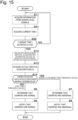
- the flowchart of Fig. 13 shows diagnostic processing (determination processing for the abnormality) executed in the control device 34.
- the processing of Fig. 13 is repeatedly executed at a predetermined control cycle (for example, every 10 msec) after the control device 34 is activated.
- a predetermined control cycle for example, every 10 msec
- Each step of processing of Fig. 13 equivalent to the processing step of Fig. 3 in the above-mentioned first embodiment is denoted by the same step number, and description thereof is omitted.
- the control device 34 acquires the information, that is, the position information (current position L) on the vehicle 1, the speed value (travel speed V) of the vehicle 1, and the pressure values P being the internal pressures of the air springs 7A and 7B, from the higher-level signals.
- the control device 34 obtains the "vertical displacements Sf (Sfl and Sfr) of the tracks at the front axle position," the “vertical displacements Sr (Srl and Srr) of the tracks at the rear axle position,” and the “mass changes ⁇ M" from the vehicle information (the current position L, the travel speed V, and the pressure values P) acquired in S11, and calculates the vehicle body vertical acceleration estimation values Gc based on the railway vehicle model.
- the control device 13 obtains the actual vertical accelerations Gr measured by the acceleration sensors 32A to 32D.
- the control device 34 determines whether or not each of the dampers 31A to 31D is normal. In this case, in S14, the control device 34 compares each of the vehicle body vertical acceleration estimation values Gc calculated in S 12 and each of the actual vertical accelerations Gr obtained in S13 with each other. That is, in S14, the control device 34 determines whether or not, for example, the difference value between each of the vehicle body vertical acceleration estimation values Gc and each of the actual vertical accelerations Gr is equal to or larger than the threshold value G1. When a determination of "NO" is made in S14, that is, the difference value between each of the vehicle body vertical acceleration estimation values Gc and each of the actual vertical accelerations Gr is determined to be smaller than the threshold value G1 in S14, the process proceeds to S5.
- the comparison may always be made in real time, or average values within a period set in advance (specified period) may be compared with each other. Further, the damper abnormality determination unit 36 may determine that each of the dampers 31A to 31D is abnormal when an integrated value of the difference between the vehicle body vertical acceleration estimation value Gc and the actual vertical acceleration Gr is equal to or larger than a specified value. That is, the numerical value processing relating to the abnormality determination (diagnosis for the operation state) is not limited to the above-mentioned processing, such as the averaging processing and effective value processing for the acceleration values and the integration of the difference value.
- the damper abnormality determination unit 36 may, for example, increase a section for the abnormality determination, may determine that the track is abnormal when the abnormality (the difference value is equal to or larger than the threshold value G1) occurs in only a specific section (short section) of the travel railroad line, and may determine that each of the dampers 31A to 31D is abnormal when the abnormality (the difference value is equal to or larger than the threshold value G1) occurs in the entire travel railroad line.
- the track abnormality and the damper abnormality may be discriminated from each other.
- the abnormality determination (operation state diagnosis) for the dampers 31A to 31D can be highly accurately made in real time based on the information always flowing through the vehicle 1 as the higher-level signals and the information on the accelerations required for the damping control for the dampers 31A to 31D during the travel of the vehicle 1.
- the second embodiment uses the above-mentioned control device 34 to determine the abnormality of each of the dampers 31A to 31D, and is not particularly different from the first embodiment in the basic actions.
- the "actual vertical acceleration Gr being the measurement value of the vertical acceleration of the vehicle body 2" and the “vehicle body vertical acceleration estimation value Gc being the estimation value of the vertical acceleration of the vehicle body 2" are compared with each other, to thereby determine the abnormality.
- the measurement values output from the existing acceleration sensors 32A to 32D can be used as the measurement values of the vertical accelerations of the vehicle body 2.
- the acceleration estimation unit 35 can use the pressure value P measured by each of the existing pressure sensors 9A and 9B and the position information acquired by the existing position sensor 11 to estimate the vehicle body vertical acceleration estimation value Gc. Further, the acceleration estimation unit 35 can use the railway vehicle model to estimate the vehicle body vertical acceleration estimation value Gc from the information on the tracks (the vertical displacements Sf and Sr of the tracks) at the position obtained from the position information, and hence the accuracy of the estimation can be increased. As a result, the accuracy of the determination of the abnormality can be increased while suppressing requirement for additional sensors.
- the acceleration estimation unit 35 estimates the vehicle body vertical acceleration estimation value Gc from the "railway vehicle model," "each of the vertical displacements Sf and Sr of the tracks obtained from the speed value output from the vehicle speed sensor 10 and the position information acquired from the existing position sensor 11," and "each of the mass changes ⁇ M of the vehicle body 2 being the information relating to the pressure value P.”
- the acceleration estimation unit 35 can use each of the vertical displacements Sf (Sfl and Sfr) of the tracks at the position corresponding to the axle on the front side (the bogie 3A on the front side) in the travel direction and each of the vertical displacements Sr (Srl and Srr) of the tracks at the position corresponding to the axle on the rear side (the bogie 3B on the rear side) in the travel direction to estimate the vehicle body vertical acceleration estimation value Gc.
- the estimation accuracy of the acceleration estimation unit 35 can be further increased.
- the configuration is not limited to this example.
- the vehicle speed sensor 10 may be omitted, and the speed value (travel speed V) calculated from the position information (current position L) of the position sensor 11 may be used to calculate the vertical displacements Sr (Srl and Srr) of the tracks at the position corresponding to the axle on the rear side (bogie 3B on the rear side) in the travel direction.
- the vehicle body acceleration estimation unit may estimate the vertical acceleration of the vehicle body from the "railway vehicle model,” the “vertical displacement of the track obtained from the speed value of the railway vehicle calculated from the position information and the position information,” and the “information relating to the pressure value.” Further, the vertical displacements of the tracks may be obtained without using the speed value.
- the abnormality determination may be made when the vehicle 1 is traveling in a travel section (between L1 and L2) set in advance at a travel speed (between V1 and V2) set in advance. That is, in the seventh modification example, the control device 34 uses the vehicle body vertical acceleration estimation value Gc at the time when the position information (current position L) is within the range (L1 ⁇ L ⁇ L2) set in advance, and the speed value (travel speed V) is within the range (V1 ⁇ V ⁇ V2) set in advance, to thereby diagnose the operation state of each of the dampers 31A to 31D.
- processing steps of S21 and S22 are added between S11 and S12 of Fig. 13 in the second embodiment. The processing steps of S21 and S22 are the same as those in the first modification example described above, and hence a further description is omitted.
- the abnormality determination may be made during a period (between t1 and t2) set in advance. That is, in the eighth modification example, the control device 34 uses the vehicle body vertical acceleration estimation value Gc at the time when the current time is within the range (t1 ⁇ t ⁇ t2) defined in advance, to thereby diagnose the operation state of each of the dampers 31A to 31D.
- processing steps of S31 and S32 are added between S11 and S12 of Fig. 13 in the second embodiment.
- the processing steps of S31 and S22 are the same as those in the second modification example described above, and hence a further description is omitted.
- the seventh modification example and the eighth modification example may be combined with each other.
- the abnormality determination (operation state diagnosis) may be made when the pressures of the air springs 7A and 7B are within a range (between P1 and P2) set in advance. That is, in the tenth modification example, the control device 34 uses the vehicle body vertical acceleration estimation value Gc at the time when the pressure P of each of the air springs 7A and 7B is within the range (P1 ⁇ P ⁇ P2) set in advance, to thereby diagnose the operation state of each of the dampers 31A to 31D.
- a processing step of S41 is added after the processing step of S32 in the ninth modification example illustrated in Fig. 16 .
- the processing step of S41 is the same as that in the fourth modification example described above, and hence a further description is omitted.
- the abnormality determination may be made when the vehicle 1 is traveling on the inbound line.
- a processing step of S51 is added in the course of the processing of the tenth modification example illustrated in Fig. 17 .
- the processing step of S51 is the same as that in the fifth modification example described above, and hence a further description is omitted.
- the abnormality determination may be made when the vehicle 1 is traveling on the outbound line.
- the processing steps of S21, S22, S32, S41, and S51 in the eleventh modification example illustrated in Fig. 18 are changed to processing steps of S61, S62, S63, S64, and S65.
- threshold values L3, L4, V3, V4, t3, and t4 for the current position, the travel speed, and the like are changed between the inbound line and the outbound line.
- all of the threshold values are not required to be changed, and, for example, the threshold values for the time, the speed, and the like may be the same.
- the spring mechanism displacement estimation unit can use the railway vehicle model to estimate the vertical displacement of the spring mechanism from the information on the track (vertical displacement of the track) at the position obtained from the position information, and hence it is possible to increase the accuracy of the estimation value of the vertical displacement of the spring mechanism. As a result, the accuracy of the determination of the abnormality can be increased while suppressing the addition of measurement means (sensors).
- the operation state diagnostic device further includes a speed measurement unit configured to measure a speed value of the railway vehicle to output the speed value
- the spring mechanism displacement estimation unit is configured to estimate the vertical displacement of the spring mechanism from the railway vehicle model, a vertical displacement of a track obtained from the speed value output from the speed measurement unit and the position information, and information relating to the pressure value.
- the spring mechanism displacement estimation unit can use, from the speed value measured by the existing speed measurement unit and the position information, the vertical displacements of the tracks at the position corresponding to the axle on the front side (front axle) in the travel direction and the vertical displacements of the tracks at the position corresponding to the axle on the rear side (rear axle) in the travel direction to estimate the vertical displacement of each spring mechanism.
- the accuracy of the estimation value of the vertical displacement of the spring mechanism obtained by the spring mechanism displacement estimation unit can be further increased.
- the shock absorber abnormality determination unit determines the abnormality by comparing the measurement value of the vertical acceleration of the vehicle body output from the vehicle body acceleration measurement unit and the estimation value of the vertical acceleration of the vehicle body output from the vehicle body acceleration estimation unit with each other.
- the measurement value output from the existing vehicle body acceleration measurement unit can be used as the measurement value of the vertical acceleration of the vehicle body.
- the vehicle body acceleration estimation unit can use the pressure value measured by the existing pressure measurement unit and the position information obtained by the existing position detection unit to estimate the vertical acceleration of the vehicle body.
- the vehicle body acceleration estimation unit is configured to estimate the vertical acceleration of the vehicle body from the railway vehicle model, a vertical displacement of a track obtained from a speed value of the railway vehicle calculated from the position information and the position information, and information relating to the pressure value.
- the vehicle body acceleration estimation unit can use, from the speed value calculated from the position information and the position information, the vertical displacements of the tracks at the position corresponding to the axle on the front side (front axle) in the travel direction and the vertical displacements of the tracks at the position corresponding to the axle on the rear side (rear axle) in the travel direction to estimate the vertical acceleration of the vehicle body.
- the accuracy of the estimation value of the vertical acceleration of the vehicle body obtained by the vehicle body acceleration estimation unit can be further increased.
- the operation state diagnostic device further includes a speed measurement unit configured to measure a speed value of the railway vehicle to output the speed value
- the vehicle body acceleration estimation unit is configured to estimate the vertical acceleration of the vehicle body from the railway vehicle model, a vertical displacement of a track obtained from the speed value output from the speed measurement unit and the position information, and information relating to the pressure value.
- the vehicle body acceleration estimation unit can use, from the speed value measured by the existing speed measurement unit and the position information, the vertical displacements of the tracks at the position corresponding to the axle on the front side (front axle) in the travel direction and the vertical displacements of the tracks at the position corresponding to the axle on the rear side (rear axle) in the travel direction to estimate the vertical acceleration of the vehicle body.
- the accuracy of the estimation value of the vertical acceleration of the vehicle body obtained by the vehicle body acceleration estimation unit can be further increased.
- the operation state diagnostic device is configured to diagnose an operation state of the shock absorber through use of the estimation value at a time when a current time is within a range determined in advance.
- the operation state of the shock absorber can be diagnosed through use of the estimation value at the time when the travel condition of the railway vehicle is relatively constant, for example, early in the morning, late at night, or in the daytime. As a result, the accuracy of the determination of the abnormality can be increased also in this respect.
- the operation state diagnostic device is configured to diagnose an operation state of the shock absorber through use of the estimation value at a time when the position information is within a range determined in advance.
- the operation state of the shock absorber can be diagnosed through use of the estimation value in the travel section in which the track is stable, such as a straight section. As a result, the accuracy of the determination of the abnormality can be increased also in this respect.
- the operation state diagnostic device is configured to diagnose an operation state of the shock absorber through use of track information corresponding to a travel direction of the railway vehicle obtained from the position information.
- the estimation can be executed through use of the track information corresponding to whether the travel direction of the railway vehicle is inbound, outbound, inner, or outer. As a result, the accuracy of the determination of the abnormality can be increased also in this respect.
Landscapes
- Physics & Mathematics (AREA)
- General Physics & Mathematics (AREA)
- Engineering & Computer Science (AREA)
- Mechanical Engineering (AREA)
- Vehicle Body Suspensions (AREA)
Description
- The present disclosure relates to an operation state diagnostic device which diagnoses a shock absorber arranged, for example, between a vehicle body and a bogie of a railway vehicle.
- There is known a vehicle in which shock absorbers are arranged between bogies and a vehicle body in order to increase ride comfort of a railway vehicle. For example, in
Patent Literature 1, there is described a technology of arranging yaw dampers serving as shock absorbers between a vehicle body and bogies of a railway vehicle, to thereby suppress bending vibration of the vehicle body while suppressing vibration of the bogies. - The shock absorber contributes to an increase in ride comfort of crews and passengers, and hence it is desired to be able to diagnose an abnormality thereof before an operation of the railway vehicle or during the operation thereof. For example, in
Patent Literature 2, there is described a technology of detecting both of vibration of bogies and vibration of wheelsets, to thereby detect a track abnormality and a bogie abnormality based on vibration values of the bogies and vibration values of the wheelsets. InPatent Literature 3, there is described a technology of vibrating a railway vehicle in a stop state, to thereby diagnose an abnormality. InPatent Literature 4, there is described a technology of detecting an acceleration in a vertical direction and an acceleration in a pitching direction, and detecting an abnormality of a shock absorber from a phase difference between a vertical translation and a pitching. -
- PTL 1:
JP 2014-198522 A - PTL 2:
JP 2004-170080 A JP 3779258 B2 - PTL 3:
JP 2019-27874 A - PTL 4:
JP 2012-111480 A JP 5662298 B2 -
JP 2005 067276 A -
JP 2017 144909 A -
CN 104 155 968 A discloses a kind of small fault diagnostic method for bullet train suspension system actuator, and particularly relates to the detection and the method for estimation of a closed-loop control system small fault based on a failure message whole step amount residual error. - In the case of the related art, in order to highly accurately determine an abnormality of a shock absorber, additional sensors may be required in addition to existing sensors.
- An object of one embodiment of the present invention is to provide an operation state diagnostic device capable of increasing an accuracy of determination of an abnormality while suppressing an addition of sensors (measurement means).
- According to one embodiment of the present invention, there is provided an operation state diagnostic device for a shock absorber arranged between a vehicle body and a bogie of a railway vehicle, the operation state diagnostic device including: a position detection unit configured to obtain a travel position of the railway vehicle to output the travel position; a pressure measurement unit configured to measure a pressure value of pressure loaded on a spring mechanism provided between the vehicle body and the bogie to output the pressure value; a spring mechanism displacement calculation unit configured to calculate a vertical displacement of the spring mechanism through use of the pressure value of the spring mechanism output from the pressure measurement unit to output the vertical displacement; a spring mechanism displacement estimation unit which is arranged on the railway vehicle, and is configured to estimate the vertical displacement of the spring mechanism through use of a railway vehicle model obtained by modeling the railway vehicle, the travel position, and the pressure value of the spring mechanism to output the vertical displacement; and a shock absorber abnormality determination unit configured to determine an abnormality of the shock absorber by comparing a calculation value of the vertical displacement of the spring mechanism output from the spring mechanism displacement calculation unit and an estimation value of the vertical displacement of the spring mechanism output from the spring mechanism displacement estimation unit with each other.
- Further, according to one embodiment of the present invention, there is provided an operation state diagnostic device for a shock absorber arranged between a vehicle body and a bogie of a railway vehicle, the operation state diagnostic device including: a vehicle body acceleration measurement unit configured to measure a vertical acceleration of the vehicle body to output the vertical acceleration; a position detection unit configured to obtain a travel position of the railway vehicle to output the travel position; a pressure measurement unit configured to measure a pressure value of pressure loaded on a spring mechanism provided between the vehicle body and the bogie to output the pressure value; a vehicle body acceleration estimation unit which is arranged on the railway vehicle, and is configured to estimate the vertical acceleration of the vehicle body through use of a railway vehicle model obtained by modeling the railway vehicle, the travel position, and the pressure value of the spring mechanism to output the vertical acceleration; and a shock absorber abnormality determination unit configured to determine an abnormality of the shock absorber by comparing a measurement value of the vertical acceleration of the vehicle body output from the vehicle body acceleration measurement unit and an estimation value of the vertical acceleration of the vehicle body output from the vehicle body acceleration estimation unit with each other.
- According to one embodiment of the present invention, it is possible to increase the accuracy of determination of the abnormality while suppressing the addition of measurement means (sensors).
-
-
Fig. 1 is a side view for schematically illustrating a railway vehicle to which an operation state diagnostic device according to a first embodiment of the present invention and shock absorbers (conventional dampers) are mounted. -
Fig. 2 is a block diagram for illustrating the diagnostic device ofFig. 1 . -
Fig. 3 is a flowchart for illustrating control processing executed by the diagnostic device ofFig. 1 . -
Fig. 4 is a flowchart for illustrating control processing executed by the diagnostic device according to a first modification example. -
Fig. 5 is a flowchart for illustrating control processing executed by the diagnostic device according to a second modification example. -
Fig. 6 is a flowchart for illustrating control processing executed by the diagnostic device according to a third modification example. -
Fig. 7 is a flowchart for illustrating control processing executed by the diagnostic device according to a fourth modification example. -
Fig. 8 is a flowchart for illustrating control processing executed by the diagnostic device according to a fifth modification example. -
Fig. 9 is a flowchart for illustrating control processing executed by the diagnostic device according to a sixth modification example. -
Fig. 10 is a side view for schematically illustrating a railway vehicle to which an operation state diagnostic device according to a second embodiment of the present invention and shock absorbers (semi-active dampers) are mounted. -
Fig. 11 is a plan view for schematically illustrating a positional relationship among a vehicle body, bogies, the shock absorbers, acceleration sensors, and the like ofFig. 10 . -
Fig. 12 is a block diagram for illustrating a control device ofFig. 10 . -
Fig. 13 is a flowchart for illustrating control processing executed by the control device ofFig. 10 . -
Fig. 14 is a flowchart for illustrating control processing executed by the control device in a seventh modification example. -
Fig. 15 is a flowchart for illustrating control processing executed by the control device in an eighth modification example. -
Fig. 16 is a flowchart for illustrating control processing executed by the control device in a ninth modification example. -
Fig. 17 is a flowchart for illustrating control processing executed by the control device in a tenth modification example. -
Fig. 18 is a flowchart for illustrating control processing executed by the control device in an eleventh modification example. -
Fig. 19 is a flowchart for illustrating control processing executed by the control device in a twelfth modification example. - Description is now given of an operation state diagnostic device according to embodiments of the present invention with reference to the accompanying drawings by giving, as an example, a case in which the operation state diagnostic device is mounted to a railway vehicle, such as an electric railcar, a diesel railcar, or a passenger railcar. In flowcharts of the drawings, a notation of "S" is used for each step (for example,
Step 1="S1"). Moreover, inFig. 1 ,Fig. 10 , andFig. 11 , description is given while assuming that a left side (one side in a length direction of the train) of the drawings is a front side in a travel direction of the railway vehicle, and a right side (another side in the length direction of the train) of the drawings is a rear side in the travel direction of the railway vehicle. However, the right side of the drawings may be the front side, and the left side of the drawings may be the rear side. -
Fig. 1 to Fig. 3 show a first embodiment of the present invention. InFig. 1 , a railway vehicle 1 (hereinafter referred to as "vehicle 1") includes avehicle body 2 on which occupants such as passengers and crews are to ride, and abogie 3A on the front side and abogie 3B on the rear side, which are provided on a lower side of thevehicle body 2. Those twobogies vehicle body 2 and the left side ofFig. 1 ) and the rear side (the another side in the length direction of thevehicle body 2 and the right side ofFig. 1 ) of thevehicle body 2, respectively. As a result, thevehicle body 2 of thevehicle 1 is installed on the pair ofbogies Fig. 1 , in order to avoid complication of the drawing, onevehicle 1, that is, a train with a single-car formation, is illustrated. However, in general, a train formed by connecting a plurality ofvehicles 1 to each other, that is, a train formed of the plurality ofvehicles 1, is in operation. - To each of the
bogies wheelsets wheel axle 5, 5 (that is, both end sides in a width direction of the vehicle body 2) are mounted apart from each other in the front-rear direction. As a result, fourwheels bogies vehicle 1 travels along left and right rails R (only one side thereof is illustrated inFig. 1 ) through rotation of thewheels vehicle body 2 is set with respect to a direction orthogonal to the travel direction as a reference. That is, the left-right direction corresponds to the width direction of the vehicle body 2 (axial direction of theaxles 5, 5). For example, inFig. 1 , a front side in a front-back direction orthogonal to the drawing sheet is left, and a back side in the front-back direction is right. - Between the
vehicle body 2 of thevehicle 1 and thebogies air springs vehicle body 2 on thebogies dampers air springs vehicle body 2 and the like forming "sprung masses" and thebogies vehicle body 2 and thebogies bogies wheels 4, 4 (wheelsets 6, 6) forming "unsprung masses" and bogie frames of thebogies bogies air springs air springs - The
dampers vehicle body 2 and thebogies vehicle 1. Each of thedampers dampers vehicle body 2 and thebogies dampers vehicle body 2 with respect to thebogies dampers vehicle body 2 in the vertical direction. Thedampers dampers bogies dampers dampers - The
pressure sensors pressure sensors pressure sensors pressure sensors pressure sensors dampers pressure sensors diagnostic device 13 via the control device (not shown) and acommunication line 14. That is, signals corresponding to the pressures measured by thepressure sensors diagnostic device 13 via the control device (not shown) and thecommunication line 14. As a result, thepressure sensors diagnostic device 13. - As illustrated in
Fig. 2 , in addition to thepressure sensors vehicle speed sensor 10 and aposition sensor 11 are provided to thevehicle 1. Thevehicle speed sensor 10 detects a travel speed (vehicle speed) of thevehicle 1. Thevehicle speed sensor 10 is connected to the control device (not shown), for example, the higher-level control device. As described later, a speed value measured by thespeed sensor 10 is used to diagnose the operation states of thedampers vehicle speed sensor 10 is connected to thediagnostic device 13 via the control device (not shown) and thecommunication line 14. That is, the signal corresponding to the vehicle speed measured by thevehicle speed sensor 10 is output to thediagnostic device 13 via the control device (not shown) and thecommunication line 14. As a result, thevehicle speed sensor 10 forms a speed measurement unit configured to measure (detect) the speed value of thevehicle 1, and to output the signal corresponding to this speed value to thediagnostic device 13. - The
position sensor 11 obtains a travel position (current position) of thevehicle 1. Theposition sensor 11 includes a receiver which receives signals from navigation satellites of a satellite positioning navigation and timing systems (SPNT) such as the GPS. Theposition sensor 11 is connected to the control device (not shown), for example, the higher-level control device. As described later, position information obtained by theposition sensor 11 is used to diagnose the operation states of thedampers position sensor 11 is connected to thediagnostic device 13 via the control device (not shown) and thecommunication line 14. That is, the signal corresponding to the position information obtained by theposition sensor 11 is output to thediagnostic device 13 via the control device (not shown) and thecommunication line 14. - As a result, the
position sensor 11 forms a position detection unit configured to obtain the position information on thebogies vehicle 1, and to output the signal corresponding to this position to thediagnostic device 13. The travel position (positions of thebogies vehicle 1 may be acquired from, in place of theposition sensor 11, a railway signal system which is used as, for example, an automatic train stop device, an automatic train control device, or a signal safety device. That is, the position detection unit may be formed of the railway signal system. Similarly, the speed measurement unit may also be formed of the railway signal system when the vehicle speed can be detected by the railway signal system. In those cases, a control device for the railway signal system mounted to thevehicle 1 corresponds to the position detection unit and/or the speed measurement unit. - Incidentally, in order to increase ride comfort of the railway vehicle, a vibration damping device is arranged between a bogie and a vehicle body (for example,
Patent Literature 1 to Patent Literature 4). It is intended that the vibration damping device suppresses vibration in the vertical direction or the left-right direction, and there exist, for example, a vibration damping device which uses a damping force adjustable shock absorber (semi-active damper) to switch a damping force in response to a vibration state and a vibration damping device which uses a control actuator (full-active damper) to actively generate a control force, to thereby suppress the vibration. Such vibration damping devices contribute to an increase in ride comfort of crews and passengers, and hence it is desired to be able to diagnose an abnormality thereof before an operation of the railway vehicle or during the operation thereof. - That is, as the speed and an added value of a railway vehicle increase, there have been developed technologies for reducing the vehicle body vibration. Of those technologies, there has been known a technology of diagnosing an abnormality (failure) of a damping force adjustable shock absorber (variable damping type shock absorber) employing a hydraulic pressure. When an abnormality of a railway vehicle is diagnosed, it is preferred to discriminate an abnormality of the track, an abnormality of the bogie, and an abnormality of the shock absorber from one another. For example, in
Patent Literature 2, there is described a technology of detecting the abnormalities of the tracks and the bogie. - Specifically, an acceleration (vibration value) of the bogie is detected by an acceleration sensor provided on each of a plurality of bogies, and an acceleration (vibration value) of a wheelset is detected by an acceleration sensor provided on each of a plurality of wheelsets, to thereby detect the track abnormality and the bogie abnormality.
- In
Patent Literature 3, there is described a technology of vibrating a railway vehicle in a stop state, to thereby diagnose an abnormality of each of devices (a bogie frame, a wheelset, an actuator, and the like) of the vehicle. Further, inPatent Literature 4, there is described a technology of detecting an acceleration in the vertical direction and an acceleration in a pitching direction, and detecting an abnormality of a shock absorber from a phase difference between a vertical translation and a pitching. However, in order to highly accurately detect the abnormality of the shock absorber provided between the bogie and the vehicle body, additional sensors such as a sensor which detects, for example, vibration of a wheelset may be required in addition to existing sensors. As a result, in addition to requirement for additional cost, a system scale may increase. - In contrast, an operation state
diagnostic device 12 according to the first embodiment can use the existing sensors to highly accurately determine (diagnose) an abnormality without requiring additional sensors. Description is now given of the operation statediagnostic device 12 according to the first embodiment. - The operation state
diagnostic device 12 diagnoses the operation states of thedampers diagnostic device 12 includes, in addition to the above-mentionedpressure sensors vehicle speed sensor 10, andposition sensor 11, thediagnostic device 13 serving as a calculation processing device which executes calculation processing for the diagnosis. Thediagnostic device 13 is provided in thevehicle 1. To thediagnostic device 13, the pressures of the air springs 7A and 7B from thepressure sensors vehicle 1 from thevehicle speed sensor 10, and the travel position (current position) of thevehicle 1 from theposition sensor 11 are input in real time via thecommunication line 14. Thus, thediagnostic device 13 is connected to the higher-level control device (not shown) via thecommunication line 14. As a result, vehicle information on the vehicle 1 (that is, vehicle information including the pressures of the air springs 7A and 7B, and the travel speed and the travel position of the vehicle 1) is input to thediagnostic device 13 as higher-level signals via thecommunication line 14. Thepressure sensors vehicle speed sensor 10, and theposition sensor 11 may be directly connected to thediagnostic device 13. - The
diagnostic device 13 is installed at a position of thevehicle 1 determined in advance (for example, a position substantially at a center of the vehicle body 2). Thediagnostic device 13 includes, for example, a microcomputer. Thediagnostic device 13 includes, as a storage unit, amemory 13A formed of a ROM, a RAM, a nonvolatile memory, and the like. In thememory 13A, for example, a processing program for executing a processing flow ofFig. 3 described later, that is, a processing program to be used to diagnose the operation states of thedampers memory 13A, in addition to reference values (for example, a reference pressure) and determination values (determination references and threshold values) to be used to diagnose the operation states, a vehicle model such as state equations to be used to calculate a state of the railway vehicle as described inPatent Literature 1 is also stored. - Moreover, in the
memory 13A, the pressures of the air springs 7A and 7B and the travel speed and the travel position of thevehicle 1 are stored in real time. Further, in thememory 13A, information (data) for obtaining, from the travel position, a vertical displacement (height position) of the track (railway) at the travel position, that is, relationships between the travel position and the vertical displacements on the left and right tracks corresponding to this travel position, are stored as maps (track maps each for each of the left and right wheels). This information (track information) can be rewritten to the latest information when, for example, inspection work, maintenance work, or change work for the tracks has been executed. - The
diagnostic device 13 acquires, in real time, the signals of the pressure values from thepressure sensors vehicle speed sensor 10, and the signal of the travel position from theposition sensor 11 during the travel of thevehicle 1. As the vehicle speed and/or the travel position, a signal of the vehicle speed and/or a signal of the travel position from the railway signal system may be used. Thediagnostic device 13 determines the abnormality of each of thedampers diagnostic device 13 executes processing of internally executing calculation based on the pressure values of the air springs 7A and 7B and the vehicle speed and the travel position of thevehicle 1, to thereby diagnose the operation states of thedampers - In this case, the
diagnostic device 13 calculates vertical displacements of the air springs 7A and 7B from the pressure values of the air springs 7A and 7B. In addition, thediagnostic device 13 uses the "railway vehicle model" to estimate the vertical displacement of each of the air springs 7A and 7B from the "vertical displacement of each of the tracks obtained from the position information" and a "mass change in air spring reaction force calculated from the pressure value of each of the air springs 7A and 7B." After that, thediagnostic device 13 compares the calculation value and the estimation value of the vertical displacement of each of the air springs 7A and 7B with each other, to thereby determine the abnormality of each of thedampers vehicle 1 is used to calculate the displacement of each of the air springs 7A and 7B as the estimation value (displacement estimation value) based on the travel speed and the current position of thevehicle 1 and the pressure sensor value of each of the air springs 7A and 7B delivered to the various devices included in thevehicle 1. Simultaneously, the displacement of each of the air springs 7A and 7B is calculated as the calculation value (displacement calculation value) from the pressure sensor value, a pressure receiving area, and a spring constant of each of the air springs 7A and 7B. Then, the estimation value and the calculation value are compared with each other, to thereby determine the abnormality of each of thedampers - Thus, as illustrated in
Fig. 2 , thediagnostic device 13 includes a referencepressure output unit 15, asubtraction unit 16, a springdisplacement calculation unit 17 which forms a spring mechanism displacement calculation unit, a spring reactionforce calculation unit 18, a masschange calculation unit 19, a track verticaldisplacement calculation unit 20 for a front axle position, a delaytime calculation unit 21, a track verticaldisplacement calculation unit 22 for a rear axle position, a springdisplacement estimation unit 23 serving as a spring mechanism displacement estimation unit, and a damperabnormality determination unit 24 serving as a shock absorber abnormality determination unit. - The reference
pressure output unit 15 outputs, to thesubtraction unit 16, a reference pressure P0 [Pa] for each of the air springs 7A and 7B stored in advance in thememory 13A. To thesubtraction unit 16, the pressure of each of the air springs 7A and 7B (for example, the pressure of each of the fourair springs pressure sensors air springs pressure output unit 15. Thesubtraction unit 16 subtracts the reference pressure P0 from the pressure P [Pa] (that is, the pressure P in real time) of each of the air springs 7A and 7B measured (detected) by each of thepressure sensors subtraction unit 16 executes calculation given byExpression 1.
- The
subtraction unit 16 outputs the calculated difference pressure ΔP (for example, the difference pressure ΔP of each of the fourair springs displacement calculation unit 17 and the spring reactionforce calculation unit 18. To the springdisplacement calculation unit 17, the difference pressure ΔP is input from thesubtraction unit 16. The springdisplacement calculation unit 17 uses the pressure value (more specifically, the difference pressure ΔP) of each of the air springs 7A and 7B output from each of thepressure sensors abnormality determination unit 24. In this case, the springdisplacement calculation unit 17 divides a product of the difference pressure ΔP of each of the air springs 7A and 7B and a pressure receiving area A [m2] by an air spring constant K [N/m], to thereby obtain an air spring displacement ΔX [m]. That is, the springdisplacement calculation unit 17 executes calculation given byExpression 2.
- The spring
displacement calculation unit 17 outputs, to the damperabnormality determination unit 24, the calculated air spring displacement ΔX (for example, the air spring displacement ΔX of each of the fourair springs force calculation unit 18, the difference pressure ΔP is input from thesubtraction unit 16. The spring reactionforce calculation unit 18 uses the pressure value (more specifically, the difference pressure ΔP) of each of the air springs 7A and 7B output from each of thepressure sensors change calculation unit 19. In this case, the spring reactionforce calculation unit 18 multiplies the difference pressure ΔP and the pressure receiving area A by each other, to thereby obtain an air spring reaction force ΔF [N]. That is, the spring reactionforce calculation unit 18 executes calculation given byExpression 3.
- The spring reaction
force calculation unit 18 outputs, to the masschange calculation unit 19, the calculated air spring reaction force ΔF (for example, the air spring reaction force ΔF of each of the fourair springs change calculation unit 19, the air spring reaction force ΔF is input from the spring reactionforce calculation unit 18. The masschange calculation unit 19 uses the first information (air spring reaction force ΔF) relating to the pressure value P of each of the air springs 7A and 7B output from the spring reactionforce calculation unit 18 to calculate a mass change ΔM, and outputs the calculation value to the springdisplacement estimation unit 23. In this case, the masschange calculation unit 19 divides the air spring reaction force ΔF by the gravity acceleration "g", to thereby obtain the mass change ΔM of thevehicle body 2 from a reference value. That is, the masschange calculation unit 19 executes calculation given byExpression 4.
- The mass
change calculation unit 19 outputs, to the springdisplacement estimation unit 23, the calculated mass change ΔM (for example, the mass change ΔM of each of the fourair springs displacement calculation unit 20, a current position L of thevehicle 1 output from theposition sensor 11 is input. The track verticaldisplacement calculation unit 20 obtains, from the current position L of thevehicle 1, the vertical displacements of the tracks at this position. Specifically, the track verticaldisplacement calculation unit 20 obtains vertical displacements Sf of the tracks (left front track vertical displacement Sfl and right front track vertical displacement Sfr) at a front axle position (for example, a position of thebogie 3A on the front side in the travel direction) from the current position L of thevehicle 1 based on the track maps (track information) for the left and right wheels (wheels 4) stored in thememory 13A of thediagnostic device 13. The track verticaldisplacement calculation unit 20 outputs the obtained vertical displacements Sf (Sfl and Sfr) of the tracks at the front axle position to the track verticaldisplacement calculation unit 22 which calculates vertical displacements Sr (left rear track vertical displacement Srl and the right rear track vertical displacement Srr) of the tracks at a rear axle position (for example, the position of thebogie 3B on the rear side in the travel direction). Moreover, the track verticaldisplacement calculation unit 20 outputs the obtained vertical displacements Sf (Sfl and Sfr) of the tracks at the front axle position to the springdisplacement estimation unit 23. - In this case, in a case in which the track vertical
displacement calculation unit 20 reads the track maps (track information), when a railroad line on which thevehicle 1 travels is a single line, the track verticaldisplacement calculation unit 20 can read the data (information) as it is. However, when the railroad line is a double line, it is preferred that the track verticaldisplacement calculation unit 20 differentiate the current position L to calculate the travel direction of the electric railcar, and discriminate track information on an inbound line and track information on outbound line from each other based on the travel direction. That is, it is preferred that, in thememory 13A, the track information on the inbound line and the track information on the outbound line be stored, and the track information corresponding to the travel direction at the time be used. A reason for this is that the tracks for thevehicle 1 are not completely the same between the inbound line and the outbound line. For example, a position and structure of a branch may be different between the inbound line and the outbound line. Further, a train travels on, for example, a passing siding or a main line of the same inbound line depending on the type of the train, and hence the train may be discriminated between a local train and a superior train (rapid, express, semi-express, and limited express) based on the position information and the speed, and track information corresponding to this discrimination may be stored in thememory 13A. - To the delay
time calculation unit 21, the travel speed V [m/s] (that is, the travel speed V in real time) of thevehicle 1 measured by thevehicle speed sensor 10 is input. The delaytime calculation unit 21 obtains a delay time τ between the front axle position and the rear axle position from the travel speed V and a distance between axles D [m] of the vehicle 1 (for example, a distance between thebogie 3A on the front side and thebogie 3B on the rear side). That is, the delaytime calculation unit 21 divides the distance between axles D [m] of thevehicle 1 by the travel speed V, to thereby obtain the delay time τ. The delaytime calculation unit 21 outputs the obtained delay time τ to the track verticaldisplacement calculation unit 22 for the rear axle position. - To the track vertical
displacement calculation unit 22 for the rear axle position, the vertical displacements Sf (Sfl and Sfr) of the tracks at the front axle position are input from the track verticaldisplacement calculation unit 20 for the front axle position, and the delay time τ is input from the delaytime calculation unit 21. The track verticaldisplacement calculation unit 22 for the rear axle position calculates vertical displacements Sr (Srl and Srr) of the tracks at the rear axle position from the vertical displacements Sf (Sfl and Sfr) of the tracks at the front axle position and the delay time τ. The track verticaldisplacement calculation unit 22 outputs the calculated vertical displacements Sr (Srl and Srr) of the tracks at the rear axle position to the springdisplacement estimation unit 23. - The spring
displacement estimation unit 23 is arranged on thevehicle 1 together with the springdisplacement calculation unit 17, the damperabnormality determination unit 24, and the like. To the springdisplacement estimation unit 23, the "mass changes ΔM of thevehicle body 2" are input from the masschange calculation unit 19, the "vertical displacements Sf (Sfl and Sfr) of the tracks at the front axle position" are input from the track verticaldisplacement calculation unit 20, and the "vertical displacements Sr (Srl and Srr) of the tracks at the rear axle position" are input from the track verticaldisplacement calculation unit 22. The springdisplacement estimation unit 23 receives the mass changes ΔM of thevehicle body 2, the vertical displacements Sf (Sfl and Sfr) of the tracks at the front axle position, and the vertical displacements Sr (Srl and Srr) of the tracks at the rear axle position as inputs, and uses the vehicle model to estimate the vertical displacements of the air springs 7A and 7B through the calculation. The springdisplacement estimation unit 23 outputs those estimation values to the damperabnormality determination unit 24 as the air spring displacement estimation values ΔXc (for example, the air spring displacement estimation values ΔXc of the fourair springs - That is, the spring
displacement estimation unit 23 uses the "railway vehicle model obtained by modeling thevehicle 1," the "position information output from the position sensor 11 (more specifically, the vertical displacements Sf and Sr of the tracks obtained from the position information)," and the "pressure values P (more specifically, the mass changes ΔM calculated from the pressure values P) of the air springs 7A and 7B" to estimate the vertical displacements of the air springs 7A and 7B, and outputs the vertical displacements to the damperabnormality determination unit 24. In more detail, the springdisplacement estimation unit 23 estimates the vertical displacements of the air springs 7A and 7B through the calculation from the "railway vehicle model," the "vertical displacements Sf and Sr of the tracks obtained from the speed value of thevehicle 1 output from thevehicle speed sensor 10 and the position information," and the "second information (mass changes ΔM) relating to the pressure values P." The springdisplacement estimation unit 23 outputs, to the damperabnormality determination unit 24, the estimated vertical displacements of the air springs 7A and 7B, that is, the air spring displacement estimation values ΔXc being the estimation values of the vertical displacements of the air springs 7A and 7B. - In this case, for example, the "vehicle model" as described in
Patent Literature 1 may be used as the railway vehicle model. That is, the springdisplacement estimation unit 23 can use the railway model (state equations) as described in paragraph [0036] and the subsequent paragraphs andFig. 3 of the drawings ofPatent Literature 1 to estimate the vertical displacements of the air springs 7A and 7B (to calculate the air spring displacement estimation values ΔXc). The springdisplacement estimation unit 23 may use a railway vehicle model (state equations) other than the model as described inPatent Literature 1. For example, a vehicle model (state equations) capable of more accurately obtaining the estimation values of the vertical displacements of the air springs 7A and 7B, that is, a vehicle model (state equations) more accurately corresponding to the structure of thevehicle 1, may be used. - To the damper
abnormality determination unit 24, the air spring displacements ΔX are input from the springdisplacement calculation unit 17, and the air spring displacement estimation values ΔXc are input from the springdisplacement estimation unit 23. The damperabnormality determination unit 24 compares each of the air spring displacements ΔX and each of the air spring displacement estimation values ΔXc with each other, to thereby determine whether each of thedampers abnormality determination unit 24 compares each of the air spring displacements ΔX which are output from the springdisplacement calculation unit 17, and are the calculation values of the vertical displacements of the air springs 7A and 7B, and each of the air spring displacement estimation values ΔXc which are output from the springdisplacement estimation unit 23, and are the estimation values of the vertical displacements of the air springs 7A and 7B with each other, to thereby determine the abnormality. The damperabnormality determination unit 24 can determine that each of thedampers dampers memory 13A. The threshold value X1 can be obtained in advance thorough, for example, calculation, experiments, simulation, or the like, and is set as a value enabling accurate determination. The damperabnormality determination unit 24 outputs (notifies) a result of determination of whether or not each of thedampers diagnostic device 13. As a result, the higher-level control device can acquire the vertical damper abnormality detection result (whether or not each of thedampers vehicle 1 or the like, to thereby notify an operator of the abnormality. - The
vehicle 1 and the operation statediagnostic device 12 mounted to thevehicle 1 in the first embodiment have the above-mentioned configuration. Next, description is given of an operation thereof. - The
vehicle 1 travels toward, for example, the left side ofFig. 1 along the rails R (tracks). When vibration such as roll (lateral oscillation) and pitch (oscillation in the front-rear direction) occurs during the travel of thevehicle 1, thedampers vehicle body 2 in the vertical direction can be reduced (suppressed). Moreover, the vehicle information on thevehicle 1, that is, the pressure values P of the air springs 7A and 7B and the current position L and the travel speed V of thevehicle 1, is input as the higher-level signals from the higher-level control device to thediagnostic device 13 via thecommunication line 14 during the travel of thevehicle 1. Thediagnostic device 13 diagnoses the operation states of thedampers diagnostic device 13 determines the abnormality of thedampers vehicle 1. - The flowchart of
Fig. 3 shows diagnostic processing (determination processing for the abnormality) executed in thediagnostic device 13. The processing ofFig. 3 is repeatedly executed at a predetermined control cycle (for example, every 10 msec) after thediagnostic device 13 is activated. - When the processing of
Fig. 3 is started, thediagnostic device 13 acquires the information from the higher-level signals in S1. That is, in S1, thediagnostic device 13 acquires, from the higher-level control device (not shown) via thecommunication line 14, the vehicle information on thevehicle 1, specifically, the position information (current position L) on thevehicle 1, the speed value (travel speed V) of thevehicle 1, and the pressure values P being the internal pressures of the air springs 7A and 7B. In S2, thediagnostic device 13 obtains the "vertical displacements Sf (Sfl and Sfr) of the tracks at the front axle position," the "vertical displacements Sr (Srl and Srr) of the tracks at the rear axle position," and the "mass changes ΔM" from the vehicle information (the current position L, the travel speed V, and the pressure values P) acquired in S1, and calculates the air spring displacement estimation values ΔXc based on the railway vehicle model. In S3, thediagnostic device 13 calculates the air spring displacements ΔX from the vehicle information (pressure values P) acquired in S1. - In S4, the
diagnostic device 13 determines whether or not each of thedampers diagnostic device 13 compares each of the air spring displacement estimation values ΔXc calculated in S2 and each of the air spring displacements ΔX calculated in S3 with each other. That is, in S4, thediagnostic device 13 determines whether or not, for example, the difference value between each of the air spring displacement estimation values ΔXc and each of the air spring displacements ΔX is equal to or larger than the threshold value X1. When a determination of "NO" is made in S4, that is, the difference value between each of the air spring displacement estimation values ΔXc and each of the air spring displacements ΔX is determined to be smaller than the threshold value X1 in S4, the process proceeds to S5. Meanwhile, when a determination of "YES" is made in S4, that is, the difference value between each of the air spring displacement estimation values ΔXc and each of the air spring displacements ΔX is determined to be equal to or larger than the threshold value X1 in S4, the process proceeds to S7. - In S5, the
diagnostic device 13 determines that each of thedamper abnormality determination unit 24 to the higher-level control device, and the process ends (returns). That is, the process returns from "END" to "START", and the processing steps subsequent to S1 are repeated. In contrast, in S7, thediagnostic device 13 determines that any of thedampers abnormality determination unit 24 to the higher-level control device, and the process ends (returns). The notification indicating that "the dampers are normal" in S6 may be combined with a notification made during the operation, or may be omitted. That is, the damperabnormality determination unit 24 may be configured to output, as the diagnostic information, the signal indicating that "damper(s) is (are) abnormal" to the higher-level control device only when the damperabnormality determination unit 24 determines that any of thedampers - In the processing step of S4, that is, when the damper
abnormality determination unit 24 compares the air spring displacement ΔX and the air spring displacement estimation value ΔXc with each other, the comparison may always be made in real time, or average values within a period set in advance (specified period) may be compared with each other. Further, the damperabnormality determination unit 24 may determine that each of thedampers - Moreover, for example, consideration is given of a case in which the difference value between the air spring displacement estimation value ΔXc and the air spring displacement ΔX of each of all of the air springs 7A and 7B is determined to be equal to or larger than the threshold value X1 in S4. In this case, it may be considered that all of the
dampers dampers Fig. 3 . Further, when the difference value between the air spring displacement ΔX and the air spring displacement estimation value ΔXc is determined to be equal to or larger than the threshold value X1, the damperabnormality determination unit 24 may, for example, increase a section of the travel railroad line for the abnormality determination, may determine that the track is abnormal when the abnormality occurs (the difference value is equal to or larger than the threshold value X1) in only a specific section (short section) of the travel railroad line, and may determine that each of thedampers dampers vehicle 1 as the higher-level signals during the travel of thevehicle 1. - As described above, in the first embodiment, the "air spring displacement ΔX being the calculation value of the vertical displacement of each of the air springs 7A and 7B" and the "air spring displacement estimation value ΔXc being the estimation value of the vertical displacement of each of the air springs 7A and 7B" are compared with each other, to thereby determine the abnormality. In this case, the spring
displacement calculation unit 17 can use the pressure value P measured by each of the existingpressure sensors displacement estimation unit 23 can use the pressure value P measured by each of the existingpressure sensors position sensor 11 to estimate the air spring displacement estimation value ΔXc. Further, the springdisplacement estimation unit 23 can use the railway vehicle model to estimate the air spring displacement estimation value ΔXc from the information on the tracks (the vertical displacements Sf and Sr of the tracks) at the position obtained from the position information, and hence the accuracy of the estimation can be increased. As a result, the accuracy of the determination of the abnormality can be increased while suppressing requirement for additional sensors. - In the first embodiment, the spring
displacement estimation unit 23 estimates the air spring displacement estimation value ΔXc from the "railway vehicle model," "each of the vertical displacements Sf and Sr of the tracks obtained from the speed value output from thevehicle speed sensor 10 and the position information acquired from the existingposition sensor 11," and "each of the mass changes ΔM of thevehicle body 2 being the information relating to the pressure value P." Thus, the springdisplacement estimation unit 23 can use each of the vertical displacements Sf (Sfl and Sfr) of the tracks at the position corresponding to the axle on the front side (thebogie 3A on the front side) in the travel direction and each of the vertical displacements Sr (Srl and Srr) of the tracks at the position corresponding to the axle on the rear side (thebogie 3B on the rear side) in the travel direction to estimate each of the air spring displacement estimation values ΔXc. As a result, the estimation accuracy of the springdisplacement estimation unit 23 can be further increased. - In the first embodiment, description has been given of, as an example, the case of the configuration in which the speed value (travel speed V) output from the
vehicle speed sensor 10 is used to calculate the vertical displacements Sr (Srl and Srr) of the tracks at the position corresponding to the axle on the rear side (bogie 3B on the rear side) in the travel direction. However, the configuration is not limited to this example. For example, thevehicle speed sensor 10 may be omitted, and the speed value (travel speed V) calculated from the position information (current position L) of theposition sensor 11 may be used to calculate the vertical displacements Sr (Srl and Srr) of the tracks at the position corresponding to the axle on the rear side (bogie 3B on the rear side) in the travel direction. - That is, the spring mechanism displacement estimation unit may estimate the vertical displacement of the spring mechanism from the "railway vehicle model," the "vertical displacement of the track obtained from the speed value of the railway vehicle calculated from the position information and the position information," and the "information relating to the pressure value." Also in this case, the spring mechanism displacement estimation unit can use the vertical displacements of the tracks at the position corresponding to the axle on the front side in the travel direction and the vertical displacements of the tracks at the position corresponding to the axle on the rear side in the travel direction to estimate the vertical displacements of the spring mechanisms. Thus, also in this case, the estimation accuracy of the spring mechanism displacement estimation unit can be further increased.
- In the first embodiment, description has been given of, as an example, the case of the configuration of using the position information (current position L) and the speed value (travel speed V) to obtain the vertical displacements Sf (Sfl and Sfr) of the tracks at the position corresponding to the axle on the front side (the
bogie 3A on the front side) in the travel direction and the vertical displacements Sr (Srl and Srr) of the tracks at the position corresponding to the axle on the rear side (thebogie 3B on the rear side) in the travel direction. However, the configuration is not limited to this example. For example, the vertical displacements of the tracks may be obtained without using the speed value. That is, the vertical displacements of the tracks at the position corresponding to the axle on the front side (the bogie on the front side) in the travel direction and the vertical displacements of the tracks at the position corresponding to the axle on the rear side (the bogie on the rear side) in the travel direction may be obtained from the current position (position information) of the railway vehicle, the track information (track maps) on the railroad line on which the railway vehicle is traveling, and dimensions of the railway vehicle. - In the first embodiment, description has been given of, as an example, the case in which the
diagnostic device 13 which executes the calculation processing for determining the abnormality of thedampers diagnostic device 13 may be built into the higher-level control device. That is, the abnormality determination for the shock absorbers may have a configuration including a dedicated arithmetic processing device (microcomputer) which makes this determination or a configuration in which this determination is made by an arithmetic processing device (microcomputer) which executes other control processing. - In the first embodiment, the abnormality determination can always be made in real time by the
diagnostic device 13 during the travel of thevehicle 1. However, the error of the calculation function (estimation function) based on the railway vehicle model of thediagnostic device 13 may increase (the accuracy of the air spring displacement estimation values ΔXc may decrease) depending on the travel speed V of thevehicle 1 and the track condition (current position L). Thus, as in a first modification example illustrated inFig. 4 , the abnormality determination (operation state diagnosis) may be made when thevehicle 1 is traveling in a travel section (between L1 and L2) set in advance at a travel speed (between V1 and V2) set in advance. - That is, in the first modification example, the
diagnostic device 13 uses the air spring displacement estimation value ΔXc at the time when the position information (current position L) is within the range (L1<L<L2) set in advance, and the speed value (travel speed V) is within the range (V1<V<V2) set in advance, to thereby diagnose the operation state of each of thedampers Fig. 3 in the first embodiment. That is, in the first modification example, as illustrated inFig. 4 , the processing steps of S21 and S22 are executed between S1 and S2. In this case, in S21 following S1, it is determined whether or not the current position L (position information) acquired in S1 is within the predetermined range, for example, between the predetermined value L1 and the predetermined value L2 (L1<L<L2). When a determination of "YES" is made in S21, the process proceeds to S22. When a determination of "NO" is made in S21, the process returns to S1. In S22, it is determined whether or not the travel speed V (speed value) acquired in S1 is within the predetermined range, for example, between the predetermined value V1 and the predetermined value V2 (V1<V<V2). When a determination of "YES" is made in S22, the process proceeds to the processing step of S2 and the subsequent steps (abnormality determination processing). When a determination of "NO" is made in S22, the process returns to S1. - As described above, in the first modification example, the section and the travel speed for the abnormality determination are set. Thus, for example, by appropriately setting the speed (predetermined values V1 and V2), the abnormality determination can be stopped under a state in which other vehicles are congested before and after the
vehicle 1 and the travel speed V of thevehicle 1 is thus lower than a normal speed in morning or evening commuting hours, for example. Moreover, by appropriately setting the section (predetermined values L1 and L2), the air spring displacement estimation values ΔXc in a section in which the tracks are extremely unstable (place inappropriate for the abnormality determination) such as sections before and after a turnout can be excluded, and the air spring displacement estimation values ΔXc in a section in which the tracks are extremely stable (place appropriate for the abnormality determination) such as a straight and horizontal section can be employed. As a result, the accuracy of the abnormality determination can be increased. That is, according to the first modification example described above, the operation states of thedampers dampers - In the first embodiment, the abnormality determination can always be made in real time by the
diagnostic device 13 during the travel of thevehicle 1. However, the error may increase depending on the travel condition of thevehicle 1 and the load condition of thevehicle body 2. Thus, the abnormality determination (operation state diagnosis) may be made during a period (between t1 and t2) set in advance as in a second modification example illustrated inFig. 5 . That is, in the second modification example, thediagnostic device 13 uses the air spring displacement estimation value ΔXc at the time when the current time is within the range (t1<t<t2) defined in advance, to thereby diagnose the operation state of each of thedampers Fig. 3 in the first embodiment. That is, in the second modification example, as illustrated inFig. 5 , the processing steps of S31 and S32 are executed between S1 and S2. In this case, in S31 following S1, a current time "t" is acquired. In S32 following S31, it is determined whether or not the current time "t" acquired in S31 is within the predetermined range, that is, for example, between a time t1 and a time t2 (t1<t<t2). When a determination of "YES" is made in S32, the process proceeds to the processing step of S2 and the subsequent steps (abnormality determination processing). When a determination of "NO" is made in S32, the process returns to S1. - As described above, in the second modification example, the time for the abnormality determination is set. Thus, by appropriately setting the times t1 and t2, the abnormality determination can be made under a condition that the travel condition of the
vehicle 1 is relatively constant, for example, early in the morning, late at night, or in the daytime. As a result, the accuracy of the abnormality determination can be increased. That is, according to the second modification example described above, the operation states of thedampers dampers vehicle 1 is relatively constant, for example, early in the morning, late at night, or in the daytime. As a result, the accuracy of the determination of the abnormality can be increased also in this respect. - Moreover,
Fig. 6 shows a third modification example. The third modification example is a combination of the first modification example and the second modification example. That is, in the third modification example, the abnormality determination (operation state diagnosis) may be made when thevehicle 1 is traveling in the travel section (between L1 and L2) set in advance at the travel speed (between V1 and V2) set in advance, and the current time is within the time (between t1 and t2) set in advance. As a result, the accuracy of the abnormality determination can be further increased. - In the first embodiment and the first modification example to the third modification example, description is given of, as an example, the case in which the abnormality determination is made independently of the values of the pressures (internal pressures) of the air springs 7A and 7B. The
vehicle 1 usually adjusts the internal pressures of the air springs 7A and 7B in response to the number of crews and passengers, to thereby maintain a vehicle height to be constant. However, for example, when the air of the air springs 7A and 7B leaks or when the internal pressures of the air springs 7A and 7B are increased to tilt the vehicle body, calculation accuracy for the estimation may decrease, resulting in an erroneous determination. Thus, as in a fourth modification example illustrated inFig. 7 , the abnormality determination (operation state diagnosis) may be made when the pressures of the air springs 7A and 7B are within a range (between P1 and P2) set in advance. - That is, in the fourth modification example, the
diagnostic device 13 uses the air spring displacement estimation value ΔXc at the time when the pressure P of each of the air springs 7A and 7B is within the range (P1<P<P2) set in advance, to thereby diagnose the operation state of each of thedampers Fig. 6 . That is, in the fourth modification example, as illustrated inFig. 7 , the processing step of S41 is executed between S32 and S2. In this case, in S41 following S32, it is determined whether or not the pressure value P of each of the air springs 7A and 7B acquired in S1 is between the pressure values P1 and P2 (P1<P<P2). When a determination of "YES" is made in S41, the process proceeds to the processing step of S2 and the subsequent steps (abnormality determination processing). When a determination of "NO" is made in S41, the process returns to S1. As described above, in the fourth modification example, the pressure for the abnormality determination is set. Thus, by appropriately setting the pressure values P1 and P2, it is possible to suppress an erroneous determination based on an estimation value at the time when the internal pressure of each of the air springs 7A and 7B is abnormal (for example, when the change in internal pressure is large). As a result, the accuracy of the abnormality determination can be increased. - In the first embodiment and the first modification example to the fourth modification example, description has been given of, as an example, the case in which the abnormality determination is made independently of the travel direction of the
vehicle 1. However, for thevehicle 1, a track state and absence/presence of a point are different between "an inbound line and an outbound line" or between "an inner line and an outer line," and hence the calculation accuracy of the estimation decreases when the same threshold value is used, and an erroneous determination may consequently be made. Thus, as in a fifth modification example illustrated inFig. 8 , the abnormality determination (operation state diagnosis) may be made when thevehicle 1 is traveling on the inbound line. Moreover, as in a sixth modification example illustrated inFig. 9 , the abnormality determination (operation state diagnosis) may be made when thevehicle 1 is traveling on the outbound line. The travel direction of thevehicle 1 can be determined from, for example, the position information. As a result, the operation states of thedampers vehicle 1 determined from the position information. - In the fifth modification example illustrated in
Fig. 8 , a processing step of S51 is added in the course of the processing of the fourth modification example illustrated inFig. 7 . In S51, it is determined whether or not the travel direction is inbound. In the sixth modification example illustrated inFig. 9 , the processing steps of S21, S22, S32, S41, and S51 in the fifth modification example illustrated inFig. 8 are changed to processing steps of S61, S62, S63, S64, and S65. That is, in the sixth modification example, threshold values (L3, L4, V3, V4, t3, and t4) for the current position, the travel speed, and the like are changed between the inbound line and the outbound line. However, all of the threshold values are not required to be changed, and, for example, the threshold values for the time, the speed, and the like may be the same. Moreover, in addition to the inbound line and the outbound line, the travel direction corresponding to the travel of the railway vehicle such as the inner line and the outer line may be selected. In this modification example, it is possible to select a travel section and a travel condition providing high calculation accuracy also in consideration of differences in travel condition including the difference between "the inbound line and the outbound line" or the difference between "the inner line and the outer line." As a result, the accuracy of the abnormality determination can be increased. - Next,
Fig. 10 to Fig. 13 show a second embodiment of the present invention. A feature of the second embodiment is a configuration in which the shock absorbers between the bogie and the wheels are damping force adjustable dampers (semi-active dampers), and the diagnosis (abnormality determination processing) for the operation state is executed by a control device which controls damping forces of the damping force adjustable dampers. In the second embodiment, the same components as those in the first embodiment are denoted by the same reference symbols, and description thereof is omitted. -
Dampers 31A to 31D serving as the shock absorbers are arranged between thevehicle body 2 and thebogies vehicle 1. Each of thedampers 31A to 31D is the damping force adjustable damper (semi-active damper) capable of adjusting the damping force, and suppresses the vibration of thebogies dampers 31A to 31D includecontrol valves 37A to 37D such as solenoid valves, respectively. A damping characteristic of each of thedampers 31A to 31D can continuously be adjusted from a hard characteristic to a soft characteristic by adjusting a valve opening pressure of each of thecontrol valves 37A to 37D through supply of electric power (drive current) from acontrol device 34. - Each of the
dampers 31A to 31D is not limited to the damper which continuously adjusts the damping characteristic, and may be a damper which can adjust the damping characteristic at two stages or a plurality of stages. Moreover, each of thedampers 31A to 31D may be a damping force adjustable shock absorber (for example, a shock absorber enclosing functional fluid such as electrorheological fluid or magnetorheological fluid) which adjusts the damping force in response to a voltage or a current. That is, as each of thedampers 31A to 31D, various types of damping force adjustable shock absorbers which can adjust (increase and decrease) the damping force at the same piston speed can be used. As illustrated inFig. 11 , two of thedampers 31A to 31D are arranged on one of thebogies dampers 31A to 31D are arranged on one vehicle 1 (twobogies dampers 31A to 31D serving as vertical dampers are arranged in parallel with air springs 7A to 7D, respectively, as in thedampers - Moreover, as illustrated in
Fig. 11 , a total of fouracceleration sensors 32A to 32D each of which measures, at a position thereof, an acceleration (vibration) in the vertical direction of thevehicle body 2 are provided at four corners of thevehicle body 2, that is, four positions apart from each other in the front-rear direction and the left-right direction of thevehicle body 2. Theacceleration sensors 32A to 32D are sensors (behavior sensors) which are mounted to the plurality of different locations of thevehicle 1, and detect a behavior (more specifically, a vibration state of the vehicle body 2) of thevehicle 1. As theacceleration sensors 32A to 32D, various types of acceleration sensors, such as a sensor of the piezoelectric type, the servo type, or the piezoresistive type or another analog acceleration sensor, can be used. - The accelerations (vertical accelerations) measured by the
acceleration sensors 32A to 32D are used to control thedampers 31A to 31D and to diagnose the operation states of thedampers 31A to 31D. Thus, theacceleration sensors 32A to 32D are connected to thecontrol device 34. Theacceleration sensors 32A to 32D form a vehicle body acceleration measurement unit configured to measure the vertical accelerations of thevehicle body 2, and to output signals corresponding to the accelerations to thecontrol device 34. The sensor arrangement on thevehicle body 2 is not limited to the form in which theacceleration sensors 32A to 32D are arranged on the front left side, the front right side, the rear left side, and the rear right side of thevehicle body 2, and may be any form such as a form in which theacceleration sensors 32A to 32D are arranged at a center of a front portion, on a left side of a center portion, on a right side of the center portion, and at a center of a rear portion of thevehicle body 2. Moreover, the number of theacceleration sensors 32A to 32D is not limited to four, and may freely be selected in accordance with a purpose of the measurement and control. For example, two, three, or five or more acceleration sensors may be provided on thevehicle body 2. - Description is now given of the
control device 34 which variably controls (adjusts) the damping force of each of thedampers 31A to 31D. - The
control device 34 is installed at a position of the vehicle 1 (for example, a position substantially at the center of the vehicle body 2) determined in advance. Thecontrol device 34 includes, for example, a microcomputer and a drive circuit. An input side of thecontrol device 34 is connected to theacceleration sensors 32A to 32D. An output side of thecontrol device 34 is connected to thedampers 31A to 31D (more specifically, thecontrol valves 37A to 37D). Thecontrol device 34 includes, as a storage unit, amemory 34A formed of a ROM, a RAM, a nonvolatile memory, and the like. In thememory 34A, for example, a processing program for controlling the damping forces of thedampers 31A to 31D is stored. Moreover, thecontrol device 34 is connected to the higher-level control device (not shown) via thecommunication line 14. To thecontrol device 34, the vehicle information on the vehicle 1 (for example, the current position L and the travel speed V of the vehicle) is input as the higher-level signals from the higher-level control device via thecommunication line 14. Theacceleration sensors 32A to 32D may be connected to the higher-level control device, and the vertical accelerations may also be input as higher-level signals to thecontrol device 34. - The
control device 34 internally executes calculation based on the sensor signals acquired from theacceleration sensors 32A to 32D and the higher-level signals acquired via thecommunication line 14, to thereby output a drive current serving as a command signal to each of thedampers 31A to 31D (more specifically, each of thecontrol valves 37A to 37D). That is, thecontrol device 34 calculates the drive current corresponding to the damping force to be generated in each of thedampers 31A to 31D in accordance with a predetermined control law (damping control logic) while reading, for example, the detection signals from theacceleration sensors 32A to 32D after each sampling time. With this configuration, thecontrol device 34 outputs the drive current to each of thecontrol valves 37A to 37D, to thereby variably control the force to be generated by each of thedampers 31A to 31D. As the control law for each of thedampers 31A to 31D, for example, the skyhook control law, the LQG control law, or the H∞ control law may be used. - With reference to
Fig. 12 , description is now given of an operation statediagnostic device 33 which diagnoses the operation state of each of thedampers 31A to 31D. Description is now mainly given of portions different from the operation statediagnostic device 12 according to the first embodiment, and a detailed description of equivalent portions is omitted. - The operation state
diagnostic device 33 according to the second embodiment diagnoses the operation states of thedampers 31A to 31D being the semi-active dampers. The operation statediagnostic device 33 includespressure sensors 9A to 9D, thevehicle speed sensor 10, theposition sensor 11, theacceleration sensors 32A to 32D, and thecontrol device 34 serving as an arithmetic processing device which executes arithmetic processing for the diagnosis. Thecontrol device 34 serves as not only a control device which executes arithmetic processing for the control of the damping forces of thedampers 31A to 31D, but also a diagnostic device which executes the arithmetic processing for the diagnosis (abnormality determination) for the operation states of thedampers 31A to 31D. Thus, in thememory 34A of thecontrol device 34, in addition to the processing program to be used to control the damping forces of thedampers 31A to 31D, a processing program for executing a processing flow illustrated inFig. 13 described later, that is, a processing program to be used to diagnose the operation states of thedampers 31A to 31D, is also stored. Moreover, in thememory 34A of thecontrol device 34, as in the above-mentioned first embodiment, the reference values, the determination values, the vehicle model, the track information (track map of each of the left and right wheels), and the like to be used to diagnose the operation states are stored. - To the
control device 34, the pressures of the air springs 7A to 7D from thepressure sensors 9A to 9D, the travel speed (vehicle speed) of thevehicle 1 from thevehicle speed sensor 10, and the travel position (current position) of thevehicle 1 from theposition sensor 11 are input via thecommunication line 14 in real time. In addition, to thecontrol device 34, the vertical accelerations of thevehicle body 2 from theacceleration sensors 32A to 32D are also input in real time. That is, thecontrol device 34 acquires, in real time, the signals of the pressure values from thepressure sensors 9A to 9D, the signal of the vehicle speed from thevehicle speed sensor 10, the signal of the travel position from theposition sensor 11, and the signals of the vertical accelerations from theacceleration sensors 32A to 32D during the travel of thevehicle 1. Thecontrol device 34 determines the abnormality of each of thedampers 31A to 31D based on those signals. Specifically, thecontrol device 34 executes processing of internally executing calculation based on the pressure values of the air springs 7A to 7D, the vehicle speed and the travel position of thevehicle 1, and the vertical accelerations of thevehicle body 2 to diagnose the operation states of thedampers 31A to 31D. - In this case, the
control device 34 uses the "railway vehicle model" to estimate the vertical accelerations of thevehicle body 2 from the "vertical displacements of the tracks obtained from the position information" and the "mass changes in air spring reaction force calculated from the pressure values of the air springs 7A to 7D." Then, thecontrol device 34 compares the estimation value of the vertical acceleration and the measurement value of the vertical acceleration measured by each of theacceleration sensors 32A to 32D with each other, to thereby determine the abnormality of each of thedampers 31A to 31D. That is, in the second embodiment, the vehicle model of thevehicle 1 is used to calculate, as the estimation value (acceleration estimation value), the vertical acceleration of thevehicle body 2 based on the travel speed and the current position of thevehicle 1 and the pressure sensor value of each of the air springs 7A to 7D delivered to the various devices included in thevehicle 1. Then, the estimation value and the measurement value of each of theacceleration sensors 32A to 32D used to control the damping force of each of thedampers 31A to 31D are compared with each other, to thereby determine the abnormality of each of thedampers 31A to 31D. - Thus, as illustrated in
Fig. 12 , thecontrol device 34 includes a referencepressure output unit 15, asubtraction unit 16, a spring reactionforce calculation unit 18, a masschange calculation unit 19, a track verticaldisplacement calculation unit 20 for a front axle position, a delaytime calculation unit 21, a track verticaldisplacement calculation unit 22 for a rear axle position, anacceleration estimation unit 35 serving as a vehicle body acceleration estimation unit, and a damperabnormality determination unit 36 serving as a shock absorber abnormality determination unit. - The
acceleration estimation unit 35 is arranged on thevehicle 1 together with the damperabnormality determination unit 36 and the like. To theacceleration estimation unit 35, the "mass changes ΔM of thevehicle body 2" are input from the masschange calculation unit 19, the "vertical displacements Sf of the tracks at the front axle position" are input from the track verticaldisplacement calculation unit 20, and the "vertical displacements Sr of the tracks at the rear axle position" are input from the track verticaldisplacement calculation unit 22. Theacceleration estimation unit 35 receives the mass changes ΔM of thevehicle body 2, the vertical displacements Sf of the tracks at the front axle position, and the vertical displacements Sr of the tracks at the rear axle position as inputs, and uses the vehicle model to estimate the vertical acceleration of thevehicle body 2 through the calculation. Theacceleration estimation unit 35 outputs those estimation values to the damperabnormality determination unit 36 as the vehicle body vertical acceleration estimation value Gc. - That is, the
acceleration estimation unit 35 uses the "railway vehicle model obtained by modeling thevehicle 1," the "position information output from the position sensor 11 (more specifically, the vertical displacements Sf and Sr of the tracks obtained from the position information)," and the "pressure values P (more specifically, the mass changes ΔM calculated from the pressure values P) of the air springs 7A and 7B" to estimate the vertical acceleration of thevehicle body 2, and outputs the vertical acceleration to the damperabnormality determination unit 36. In more detail, theacceleration estimation unit 35 estimates the vertical acceleration of thevehicle body 2 through the calculation from the "railway vehicle model," the "vertical displacements Sf and Sr of the tracks obtained from the speed value of thevehicle 1 output from thevehicle speed sensor 10 and the position information," and the "second information (mass changes ΔM) relating to the pressure values P." Theacceleration estimation unit 35 outputs, to the damperabnormality determination unit 36, the estimated vertical acceleration of thevehicle body 2, that is, the vehicle body vertical acceleration estimation value Gc being the estimation value of the vertical acceleration of thevehicle body 2. - In this case, for example, the "vehicle model" as described in
Patent Literature 1 may be used as the railway vehicle model. That is, theacceleration estimation unit 35 can use the railway model (state equations) as described in paragraph [0036] and the subsequent paragraphs andFig. 3 of the drawings ofPatent Literature 1 to estimate the vertical acceleration of the vehicle body 2 (to calculate the vehicle body vertical acceleration estimation value Gc). Theacceleration estimation unit 35 may use a railway vehicle model (state equations) other than the model as described inPatent Literature 1. For example, a vehicle model (state equations) capable of more accurately obtaining the estimation values of the vertical acceleration of thevehicle body 2, that is, a vehicle model (state equations) more accurately corresponding to the structure of thevehicle 1, may be used. - To the damper
abnormality determination unit 36, the measurement value of the vertical acceleration of thevehicle body 2 measured by each of theacceleration sensors 32A to 32D, that is, an actual vertical acceleration Gr, is input. Moreover, to the damperabnormality determination unit 36, the vehicle body vertical acceleration estimation value Gc is input from theacceleration estimation unit 35. The damperabnormality determination unit 36 compares the actual vertical acceleration Gr and the vehicle body vertical acceleration estimation value Gc with each other, to thereby determine whether each of thedampers 31A to 31D is normal or abnormal. That is, the damperabnormality determination unit 36 compares the actual vertical acceleration Gr being the measurement value of the vertical acceleration of thevehicle body 2 output from each of theacceleration sensors 32A to 32D and the vehicle body vertical acceleration estimation value Gc being the estimation value of the vertical acceleration of thevehicle body 2 output from theacceleration estimation unit 35 with each other, to thereby determine the abnormality. The damperabnormality determination unit 36 can determine that each of thedampers 31A to 31D is abnormal when, for example, a difference value between the actual vertical acceleration Gr and the vehicle body vertical acceleration estimation value Gc is equal to or larger than a threshold value G1 set in advance. The threshold value G1 is obtained in advance through calculation, experiments, simulation, or the like so that whether each of thedampers 31A to 31D is normal or abnormal can be accurately determined. The damperabnormality determination unit 36 outputs a result of determination of whether or not each of thedampers 31A to 31D is normal, that is, the vertical damper abnormality detection result, to the higher-level control device as diagnostic information of thecontrol device 34. As a result, the higher-level control device can acquire the vertical damper abnormality detection result (whether or not each of thedampers 31A to 31D is normal). - The flowchart of
Fig. 13 shows diagnostic processing (determination processing for the abnormality) executed in thecontrol device 34. The processing ofFig. 13 is repeatedly executed at a predetermined control cycle (for example, every 10 msec) after thecontrol device 34 is activated. Each step of processing ofFig. 13 equivalent to the processing step ofFig. 3 in the above-mentioned first embodiment is denoted by the same step number, and description thereof is omitted. - When the processing of
Fig. 13 is started, inS 11, thecontrol device 34 acquires the information, that is, the position information (current position L) on thevehicle 1, the speed value (travel speed V) of thevehicle 1, and the pressure values P being the internal pressures of the air springs 7A and 7B, from the higher-level signals. In S12, thecontrol device 34 obtains the "vertical displacements Sf (Sfl and Sfr) of the tracks at the front axle position," the "vertical displacements Sr (Srl and Srr) of the tracks at the rear axle position," and the "mass changes ΔM" from the vehicle information (the current position L, the travel speed V, and the pressure values P) acquired in S11, and calculates the vehicle body vertical acceleration estimation values Gc based on the railway vehicle model. In S13, thecontrol device 13 obtains the actual vertical accelerations Gr measured by theacceleration sensors 32A to 32D. - In S14, the
control device 34 determines whether or not each of thedampers 31A to 31D is normal. In this case, in S14, thecontrol device 34 compares each of the vehicle body vertical acceleration estimation values Gc calculated inS 12 and each of the actual vertical accelerations Gr obtained in S13 with each other. That is, in S14, thecontrol device 34 determines whether or not, for example, the difference value between each of the vehicle body vertical acceleration estimation values Gc and each of the actual vertical accelerations Gr is equal to or larger than the threshold value G1. When a determination of "NO" is made in S14, that is, the difference value between each of the vehicle body vertical acceleration estimation values Gc and each of the actual vertical accelerations Gr is determined to be smaller than the threshold value G1 in S14, the process proceeds to S5. Meanwhile, when a determination of "YES" is made in S14, that is, the difference value between each of the vehicle body vertical acceleration estimation values Gc and each of the actual vertical accelerations Gr is determined to be equal to or larger than the threshold value G1 in S14, the process proceeds to S7. - In the processing step of S14, that is, when the damper
abnormality determination unit 36 compares the vehicle body vertical acceleration estimation value Gc and the actual vertical acceleration Gr with each other, the comparison may always be made in real time, or average values within a period set in advance (specified period) may be compared with each other. Further, the damperabnormality determination unit 36 may determine that each of thedampers 31A to 31D is abnormal when an integrated value of the difference between the vehicle body vertical acceleration estimation value Gc and the actual vertical acceleration Gr is equal to or larger than a specified value. That is, the numerical value processing relating to the abnormality determination (diagnosis for the operation state) is not limited to the above-mentioned processing, such as the averaging processing and effective value processing for the acceleration values and the integration of the difference value. Moreover, for example, when all of thedampers 31A to 31D (fourdampers 31A to 31D) are simultaneously determined to be abnormal, the possibility of this abnormal state is low, and hence it may be determined that a track abnormality occurs in thevehicle body 2. Further, when the difference value between the vehicle body vertical acceleration estimation value Gc and the actual vertical acceleration Gr is determined to be equal to or larger than the threshold value G1, the damperabnormality determination unit 36 may, for example, increase a section for the abnormality determination, may determine that the track is abnormal when the abnormality (the difference value is equal to or larger than the threshold value G1) occurs in only a specific section (short section) of the travel railroad line, and may determine that each of thedampers 31A to 31D is abnormal when the abnormality (the difference value is equal to or larger than the threshold value G1) occurs in the entire travel railroad line. That is, the track abnormality and the damper abnormality may be discriminated from each other. In any case, in the second embodiment, the abnormality determination (operation state diagnosis) for thedampers 31A to 31D can be highly accurately made in real time based on the information always flowing through thevehicle 1 as the higher-level signals and the information on the accelerations required for the damping control for thedampers 31A to 31D during the travel of thevehicle 1. - The second embodiment uses the above-mentioned
control device 34 to determine the abnormality of each of thedampers 31A to 31D, and is not particularly different from the first embodiment in the basic actions. In particular, according to the second embodiment, the "actual vertical acceleration Gr being the measurement value of the vertical acceleration of thevehicle body 2" and the "vehicle body vertical acceleration estimation value Gc being the estimation value of the vertical acceleration of thevehicle body 2" are compared with each other, to thereby determine the abnormality. In this case, the measurement values output from the existingacceleration sensors 32A to 32D can be used as the measurement values of the vertical accelerations of thevehicle body 2. Moreover, theacceleration estimation unit 35 can use the pressure value P measured by each of the existingpressure sensors position sensor 11 to estimate the vehicle body vertical acceleration estimation value Gc. Further, theacceleration estimation unit 35 can use the railway vehicle model to estimate the vehicle body vertical acceleration estimation value Gc from the information on the tracks (the vertical displacements Sf and Sr of the tracks) at the position obtained from the position information, and hence the accuracy of the estimation can be increased. As a result, the accuracy of the determination of the abnormality can be increased while suppressing requirement for additional sensors. - In the second embodiment, the
acceleration estimation unit 35 estimates the vehicle body vertical acceleration estimation value Gc from the "railway vehicle model," "each of the vertical displacements Sf and Sr of the tracks obtained from the speed value output from thevehicle speed sensor 10 and the position information acquired from the existingposition sensor 11," and "each of the mass changes ΔM of thevehicle body 2 being the information relating to the pressure value P." Thus, theacceleration estimation unit 35 can use each of the vertical displacements Sf (Sfl and Sfr) of the tracks at the position corresponding to the axle on the front side (thebogie 3A on the front side) in the travel direction and each of the vertical displacements Sr (Srl and Srr) of the tracks at the position corresponding to the axle on the rear side (thebogie 3B on the rear side) in the travel direction to estimate the vehicle body vertical acceleration estimation value Gc. As a result, the estimation accuracy of theacceleration estimation unit 35 can be further increased. - In the second embodiment, description has been given of, as an example, the case of the configuration in which the speed value (travel speed V) output from the
vehicle speed sensor 10 is used to calculate the vertical displacements Sr (Srl and Srr) of the tracks at the position corresponding to the axle on the rear side (bogie 3B on the rear side) in the travel direction. However, the configuration is not limited to this example. For example, thevehicle speed sensor 10 may be omitted, and the speed value (travel speed V) calculated from the position information (current position L) of theposition sensor 11 may be used to calculate the vertical displacements Sr (Srl and Srr) of the tracks at the position corresponding to the axle on the rear side (bogie 3B on the rear side) in the travel direction. - That is, the vehicle body acceleration estimation unit may estimate the vertical acceleration of the vehicle body from the "railway vehicle model," the "vertical displacement of the track obtained from the speed value of the railway vehicle calculated from the position information and the position information," and the "information relating to the pressure value." Further, the vertical displacements of the tracks may be obtained without using the speed value.
- In the second embodiment, description has been given of the case of, as an example, the configuration in which the calculation processing for the abnormal determination for the
dampers 31A to 31D is also executed by thecontrol device 34 which controls the damping forces of thedampers 31A to 31D. However, the configuration is not limited to this example, and a control device which executes the calculation processing for the control for the damping forces of the shock absorbers and a control device which executes the calculation processing for the abnormality determination for the shock absorbers may be provided independently of each other. - Further, for example, as in a seventh modification example illustrated in
Fig. 14 , the abnormality determination (operation state diagnosis) may be made when thevehicle 1 is traveling in a travel section (between L1 and L2) set in advance at a travel speed (between V1 and V2) set in advance. That is, in the seventh modification example, thecontrol device 34 uses the vehicle body vertical acceleration estimation value Gc at the time when the position information (current position L) is within the range (L1<L<L2) set in advance, and the speed value (travel speed V) is within the range (V1<V<V2) set in advance, to thereby diagnose the operation state of each of thedampers 31A to 31D. Thus, in the seventh modification example, processing steps of S21 and S22 are added between S11 and S12 ofFig. 13 in the second embodiment. The processing steps of S21 and S22 are the same as those in the first modification example described above, and hence a further description is omitted. - Further, for example, as in an eighth modification example illustrated in
Fig. 15 , the abnormality determination (operation state diagnosis) may be made during a period (between t1 and t2) set in advance. That is, in the eighth modification example, thecontrol device 34 uses the vehicle body vertical acceleration estimation value Gc at the time when the current time is within the range (t1<t<t2) defined in advance, to thereby diagnose the operation state of each of thedampers 31A to 31D. Thus, in the eighth modification example, as illustrated inFig. 15 , processing steps of S31 and S32 are added between S11 and S12 ofFig. 13 in the second embodiment. The processing steps of S31 and S22 are the same as those in the second modification example described above, and hence a further description is omitted. - Moreover, for example, as in a ninth modification example illustrated in
Fig. 16 , the seventh modification example and the eighth modification example may be combined with each other. Further, as in a tenth modification example illustrated inFig. 17 , the abnormality determination (operation state diagnosis) may be made when the pressures of the air springs 7A and 7B are within a range (between P1 and P2) set in advance. That is, in the tenth modification example, thecontrol device 34 uses the vehicle body vertical acceleration estimation value Gc at the time when the pressure P of each of the air springs 7A and 7B is within the range (P1<P<P2) set in advance, to thereby diagnose the operation state of each of thedampers 31A to 31D. Thus, in the tenth modification example, a processing step of S41 is added after the processing step of S32 in the ninth modification example illustrated inFig. 16 . The processing step of S41 is the same as that in the fourth modification example described above, and hence a further description is omitted. - Moreover, as in an eleventh modification example illustrated in
Fig. 18 , the abnormality determination (operation state diagnosis) may be made when thevehicle 1 is traveling on the inbound line. In the eleventh modification example, a processing step of S51 is added in the course of the processing of the tenth modification example illustrated inFig. 17 . The processing step of S51 is the same as that in the fifth modification example described above, and hence a further description is omitted. Moreover, as in a twelfth modification example illustrated inFig. 19 , the abnormality determination (operation state diagnosis) may be made when thevehicle 1 is traveling on the outbound line. In the twelfth modification example, the processing steps of S21, S22, S32, S41, and S51 in the eleventh modification example illustrated inFig. 18 are changed to processing steps of S61, S62, S63, S64, and S65. As a result, in the twelfth modification example, threshold values (L3, L4, V3, V4, t3, and t4) for the current position, the travel speed, and the like are changed between the inbound line and the outbound line. However, all of the threshold values are not required to be changed, and, for example, the threshold values for the time, the speed, and the like may be the same. - In the first embodiment, description has been given of, as an example, the case in which the
dampers vehicle body 2 and thebogies dampers - In the first embodiment and the second embodiment, description has been given of, as an example, the case in which the spring mechanisms provided between the
vehicle body 2 and thebogies - In the second embodiment, a description has been given of, as an example, the case in which the
acceleration sensors 32A to 32D are provided on thevehicle body 2. However, the configuration is not limited to this example, and the acceleration sensors may be provided on the bogies. Moreover, the acceleration sensors may be provided on both of the vehicle body and the bogies. - In the second embodiment, description has been given of, as an example, the case of the configuration that the vertical accelerations (the actual vertical accelerations Gr and the vehicle body vertical acceleration estimation values Gc) of the
vehicle body 2 are used to determine the abnormality. However, the configuration is not limited to this example, and for example, both of the "vertical accelerations (measurement values and estimation values) of the vehicle body" as in the second embodiment and the "vertical displacements (calculation values and estimation values) of the air springs" as in the first embodiment may be used to determine the abnormality. This also applies to the seventh modification example to the twelfth modification example. Moreover, also in the first embodiment and the first modification example to the sixth modification example, for example, the vehicle body acceleration measurement unit (acceleration sensors) may be provided on a vehicle to which conventional dampers are mounted, to thereby determine the abnormality through use of the vertical accelerations of the vehicle body, and both of the vertical accelerations of the vehicle body and the vertical displacements of the air springs may be used to determine the abnormality. - Further, each of the embodiments and the modification examples is an example, and it is to be understood that the configurations as described in the different embodiments can be partially replaced or combined.
- As the operation state diagnostic device according to the embodiments described above, for example, the following aspects are conceivable.
- As a first aspect, there is provided an operation state diagnostic device for a shock absorber arranged between a vehicle body and a bogie of a railway vehicle, the operation state diagnostic device including: a position detection unit configured to obtain position information on the bogie to output the position information; a pressure measurement unit configured to measure a pressure value of pressure loaded on a spring mechanism provided between the vehicle body and the bogie to output the pressure value; a spring mechanism displacement calculation unit configured to calculate a vertical displacement of the spring mechanism through use of the pressure value of the spring mechanism output from the pressure measurement unit to output the vertical displacement; a spring mechanism displacement estimation unit which is arranged on the railway vehicle, and is configured to estimate the vertical displacement of the spring mechanism through use of a railway vehicle model obtained by modeling the railway vehicle, the position information, and the pressure value of the spring mechanism to output the vertical displacement; and a shock absorber abnormality determination unit configured to determine an abnormality of the shock absorber by comparing a calculation value of the vertical displacement of the spring mechanism output from the spring mechanism displacement calculation unit and an estimation value of the vertical displacement of the spring mechanism output from the spring mechanism displacement estimation unit with each other.
- According to this first aspect, the shock absorber abnormality determination unit determines the abnormality by comparing the calculation value of the vertical displacement of the spring mechanism output from the spring mechanism displacement calculation unit and the estimation value of the vertical displacement of the spring mechanism output from the spring mechanism displacement estimation unit with each other. In this case, the spring mechanism displacement calculation unit can use the pressure value measured by the existing pressure measurement unit to calculate the vertical displacement of the spring mechanism. Moreover, the spring mechanism displacement estimation unit can use the pressure value measured by the existing pressure measurement unit and the position information obtained by the existing position detection unit to estimate the vertical displacement of the spring mechanism. Further, the spring mechanism displacement estimation unit can use the railway vehicle model to estimate the vertical displacement of the spring mechanism from the information on the track (vertical displacement of the track) at the position obtained from the position information, and hence it is possible to increase the accuracy of the estimation value of the vertical displacement of the spring mechanism. As a result, the accuracy of the determination of the abnormality can be increased while suppressing the addition of measurement means (sensors).
- As a second aspect, in the first aspect, the spring mechanism displacement estimation unit is configured to estimate the vertical displacement of the spring mechanism from the railway vehicle model, a vertical displacement of a track obtained from a speed value of the railway vehicle calculated from the position information and the position information, and information relating to the pressure value. According to this second aspect, the spring mechanism displacement estimation unit can use, from the speed value calculated from the position information and the position information, the vertical displacements of the tracks at the position corresponding to the axle on the front side (front axle) in the travel direction and the vertical displacements of the tracks at the position corresponding to the axle on the rear side (rear axle) in the travel direction to estimate the vertical displacement of each spring mechanism. As a result, the accuracy of the estimation value of the vertical displacement of the spring mechanism obtained by the spring mechanism displacement estimation unit can be further increased.
- As a third aspect, in the first aspect, the operation state diagnostic device further includes a speed measurement unit configured to measure a speed value of the railway vehicle to output the speed value, and the spring mechanism displacement estimation unit is configured to estimate the vertical displacement of the spring mechanism from the railway vehicle model, a vertical displacement of a track obtained from the speed value output from the speed measurement unit and the position information, and information relating to the pressure value. According to this third aspect, the spring mechanism displacement estimation unit can use, from the speed value measured by the existing speed measurement unit and the position information, the vertical displacements of the tracks at the position corresponding to the axle on the front side (front axle) in the travel direction and the vertical displacements of the tracks at the position corresponding to the axle on the rear side (rear axle) in the travel direction to estimate the vertical displacement of each spring mechanism. As a result, the accuracy of the estimation value of the vertical displacement of the spring mechanism obtained by the spring mechanism displacement estimation unit can be further increased.
- As a fourth aspect, there is provided an operation state diagnostic device for a shock absorber arranged between a vehicle body and a bogie of a railway vehicle, the operation state diagnostic device including: a vehicle body acceleration measurement unit configured to measure a vertical acceleration of the vehicle body to output the vertical acceleration; a position detection unit configured to obtain position information on the bogie to output the position information; a pressure measurement unit configured to measure a pressure value of pressure loaded on a spring mechanism provided between the vehicle body and the bogie to output the pressure value; a vehicle body acceleration estimation unit which is arranged on the railway vehicle, and is configured to estimate the vertical acceleration of the vehicle body through use of a railway vehicle model obtained by modeling the railway vehicle, the position information, and the pressure value of the spring mechanism to output the vertical acceleration; and a shock absorber abnormality determination unit configured to determine an abnormality of the shock absorber by comparing a measurement value of the vertical acceleration of the vehicle body output from the vehicle body acceleration measurement unit and an estimation value of the vertical acceleration of the vehicle body output from the vehicle body acceleration estimation unit with each other.
- According to this fourth aspect, the shock absorber abnormality determination unit determines the abnormality by comparing the measurement value of the vertical acceleration of the vehicle body output from the vehicle body acceleration measurement unit and the estimation value of the vertical acceleration of the vehicle body output from the vehicle body acceleration estimation unit with each other. In this case, the measurement value output from the existing vehicle body acceleration measurement unit can be used as the measurement value of the vertical acceleration of the vehicle body. Moreover, the vehicle body acceleration estimation unit can use the pressure value measured by the existing pressure measurement unit and the position information obtained by the existing position detection unit to estimate the vertical acceleration of the vehicle body. Further, the vehicle body acceleration estimation unit can use the railway vehicle model to estimate the vertical acceleration of the vehicle body from the information on the track (vertical displacement of the track) at the position obtained from the position information, and hence it is possible to increase the accuracy of the estimation value of the vertical acceleration of the vehicle body. As a result, the accuracy of the determination of the abnormality can be increased while suppressing the addition of measurement means (sensors).
- As a fifth aspect, in the fourth aspect, the vehicle body acceleration estimation unit is configured to estimate the vertical acceleration of the vehicle body from the railway vehicle model, a vertical displacement of a track obtained from a speed value of the railway vehicle calculated from the position information and the position information, and information relating to the pressure value. According to this fifth aspect, the vehicle body acceleration estimation unit can use, from the speed value calculated from the position information and the position information, the vertical displacements of the tracks at the position corresponding to the axle on the front side (front axle) in the travel direction and the vertical displacements of the tracks at the position corresponding to the axle on the rear side (rear axle) in the travel direction to estimate the vertical acceleration of the vehicle body. As a result, the accuracy of the estimation value of the vertical acceleration of the vehicle body obtained by the vehicle body acceleration estimation unit can be further increased.
- As a sixth aspect, in the fourth aspect, the operation state diagnostic device further includes a speed measurement unit configured to measure a speed value of the railway vehicle to output the speed value, and the vehicle body acceleration estimation unit is configured to estimate the vertical acceleration of the vehicle body from the railway vehicle model, a vertical displacement of a track obtained from the speed value output from the speed measurement unit and the position information, and information relating to the pressure value. According to this sixth aspect, the vehicle body acceleration estimation unit can use, from the speed value measured by the existing speed measurement unit and the position information, the vertical displacements of the tracks at the position corresponding to the axle on the front side (front axle) in the travel direction and the vertical displacements of the tracks at the position corresponding to the axle on the rear side (rear axle) in the travel direction to estimate the vertical acceleration of the vehicle body. As a result, the accuracy of the estimation value of the vertical acceleration of the vehicle body obtained by the vehicle body acceleration estimation unit can be further increased.
- As a seventh aspect, in any one of the first aspect to the sixth aspect, the operation state diagnostic device is configured to diagnose an operation state of the shock absorber through use of the estimation value at a time when a current time is within a range determined in advance. According to this seventh aspect, the operation state of the shock absorber can be diagnosed through use of the estimation value at the time when the travel condition of the railway vehicle is relatively constant, for example, early in the morning, late at night, or in the daytime. As a result, the accuracy of the determination of the abnormality can be increased also in this respect.
- As an eighth aspect, in any one of the first aspect to the sixth aspect, the operation state diagnostic device is configured to diagnose an operation state of the shock absorber through use of the estimation value at a time when the position information is within a range determined in advance. According to this eighth aspect, the operation state of the shock absorber can be diagnosed through use of the estimation value in the travel section in which the track is stable, such as a straight section. As a result, the accuracy of the determination of the abnormality can be increased also in this respect.
- As a ninth aspect, in any one of the first aspect to the sixth aspect, the operation state diagnostic device is configured to diagnose an operation state of the shock absorber through use of track information corresponding to a travel direction of the railway vehicle obtained from the position information. According to this ninth aspect, the estimation can be executed through use of the track information corresponding to whether the travel direction of the railway vehicle is inbound, outbound, inner, or outer. As a result, the accuracy of the determination of the abnormality can be increased also in this respect.
- The present application claims a priority based on
Japanese Patent Application No. 2020-020837 filed on February 10, 2020 - 1 vehicle (railway vehicle), 2 vehicle body, 3A, 3B bogie, 7A-7D air spring (spring mechanism), 8A, 8B, 31A-31D damper (shock absorber), 9A-9D pressure sensor (pressure measurement unit), 10 vehicle speed sensor (speed measurement unit), 11 position sensor (position detection unit), 12, 33 operation state diagnostic device, 17 spring displacement calculation unit (spring mechanism displacement calculation unit), 23 spring displacement estimation unit (spring mechanism displacement estimation unit), 24, 36 damper abnormality determination unit (shock absorber abnormality determination unit), 32A-32D acceleration sensor (vehicle body acceleration measurement unit), 35 acceleration estimation unit (vehicle body acceleration estimation unit), ΔF air spring reaction force (information), Gc vehicle body vertical acceleration estimation value (estimation value), Gr actual vertical acceleration (measurement value), L current position (position information), ΔM mass change (information), P pressure value, V travel speed (speed value), ΔX air spring displacement (calculation value), ΔXc air spring displacement estimation value (estimation value)
Claims (9)
- An operation state diagnostic device (12, 33) for a shock absorber (8A, 8B, 31A - 31D) arranged between a vehicle body (2) and a bogie (3A, 3B) of a railway vehicle (1), the operation state diagnostic device (12, 33) comprising:a position detection unit (11) configured to obtain a travel position of the railway vehicle (1) to output the travel position;a pressure measurement unit (9A - 9D) configured to measure a pressure value of pressure loaded on a spring mechanism (7A - 7D) provided between the vehicle body (2) and the bogie (3A, 3B) to output the pressure value;a spring mechanism displacement calculation unit (17) configured to calculate a vertical displacement of the spring mechanism (7A - 7D) through use of the pressure value of the spring mechanism (7A - 7D) output from the pressure measurement unit (9A - 9D) to output the vertical displacement;a spring mechanism displacement estimation unit (23) which is arranged on the railway vehicle (1), and is configured to estimate the vertical displacement of the spring mechanism (7A - 7D) through use of a railway vehicle model obtained by modeling the railway vehicle (1), the travel position, and the pressure value of the spring mechanism (7A - 7D) to output the vertical displacement; anda shock absorber abnormality determination unit (24, 36) configured to determine an abnormality of the shock absorber (8A, 8B, 31A - 31D) by comparing a calculation value of the vertical displacement of the spring mechanism (7A - 7D) output from the spring mechanism displacement calculation unit (17) and an estimation value of the vertical displacement of the spring mechanism (7A - 7D) output from the spring mechanism displacement estimation unit (23) with each other.
- The operation state diagnostic device (12, 33) according to claim 1, wherein the spring mechanism displacement estimation unit (23) is configured to estimate the vertical displacement of the spring mechanism (7A - 7D) from the railway vehicle model, a vertical displacement of a track obtained from a speed value of the railway vehicle (1) calculated from the travel position and the travel position, and information relating to the pressure value.
- The operation state diagnostic device (12, 33) according to claim 1, further comprising a speed measurement unit (10) configured to measure a speed value of the railway vehicle (1) to output the speed value,
wherein the spring mechanism displacement estimation unit (23) is configured to estimate the vertical displacement of the spring mechanism (7A - 7D) from the railway vehicle model, a vertical displacement of a track obtained from the speed value output from the speed measurement unit (10) and the travel position, and information relating to the pressure value. - An operation state diagnostic device (12, 33) for a shock absorber (8A, 8B, 31A - 31D) arranged between a vehicle body (2) and a bogie (3A, 3B) of a railway vehicle (1), the operation state diagnostic device (12, 33) comprising:a vehicle body acceleration measurement unit (32A - 32D) configured to measure a vertical acceleration of the vehicle body (2) to output the vertical acceleration;a position detection unit (11) configured to obtain a travel position of the railway vehicle (1) to output the travel position;a pressure measurement unit (9A - 9D) configured to measure a pressure value of pressure loaded on a spring mechanism (7A - 7D) provided between the vehicle body (2) and the bogie (3A, 3B) to output the pressure value;a vehicle body acceleration estimation unit (35) which is arranged on the railway vehicle (1), and is configured to estimate the vertical acceleration of the vehicle body (2) through use of a railway vehicle model obtained by modeling the railway vehicle (1), the travel position, and the pressure value of the spring mechanism (7A - 7D) to output the vertical acceleration; anda shock absorber abnormality determination unit (24, 36) configured to determine an abnormality of the shock absorber (8A, 8B, 31A - 31D) by comparing a measurement value of the vertical acceleration of the vehicle body (2) output from the vehicle body acceleration measurement unit (32A - 32D) and an estimation value of the vertical acceleration of the vehicle body (2) output from the vehicle body acceleration estimation unit (35) with each other.
- The operation state diagnostic device (12, 33) according to claim 4, wherein the vehicle body acceleration estimation unit (35) is configured to estimate the vertical acceleration of the vehicle body (2) from the railway vehicle model, a vertical displacement of a track obtained from a speed value of the railway vehicle (1) calculated from the travel position and the travel position, and information relating to the pressure value.
- The operation state diagnostic device (12, 33) according to claim 4, further comprising a speed measurement unit (10) configured to measure a speed value of the railway vehicle (1) to output the speed value,
wherein the vehicle body acceleration estimation unit (35) is configured to estimate the vertical acceleration of the vehicle body (2) from the railway vehicle model, a vertical displacement of a track obtained from the speed value output from the speed measurement unit (10) and the travel position, and information relating to the pressure value. - The operation state diagnostic device (12, 33) according to any one of claims 1 to 6, wherein the operation state diagnostic device (12, 33) is configured to diagnose an operation state of the shock absorber (8A, 8B, 31A - 31D) through use of the estimation value at a time when a current time is within a range determined in advance.
- The operation state diagnostic device (12, 33) according to any one of claims 1 to 6, wherein the operation state diagnostic device (12, 33) is configured to diagnose an operation state of the shock absorber (8A, 8B, 31A - 31D) through use of the estimation value at a time when the travel position is within a range determined in advance.
- The operation state diagnostic device (12, 33) according to any one of claims 1 to 6, wherein the operation state diagnostic device (12, 33) is configured to diagnose an operation state of the shock absorber (8A, 8B, 31A - 31D) through use of a vertical displacement of a track corresponding to a travel direction of the railway vehicle (1) obtained from the travel position.
Applications Claiming Priority (2)
| Application Number | Priority Date | Filing Date | Title |
|---|---|---|---|
| JP2020020837 | 2020-02-10 | ||
| PCT/JP2021/004321 WO2021161916A1 (en) | 2020-02-10 | 2021-02-05 | Operation state diagnostic device |
Publications (3)
| Publication Number | Publication Date |
|---|---|
| EP4105098A1 EP4105098A1 (en) | 2022-12-21 |
| EP4105098A4 EP4105098A4 (en) | 2023-08-23 |
| EP4105098B1 true EP4105098B1 (en) | 2024-09-25 |
Family
ID=77292231
Family Applications (1)
| Application Number | Title | Priority Date | Filing Date |
|---|---|---|---|
| EP21753205.0A Active EP4105098B1 (en) | 2020-02-10 | 2021-02-05 | Operation state diagnostic device |
Country Status (4)
| Country | Link |
|---|---|
| EP (1) | EP4105098B1 (en) |
| JP (1) | JP7204041B2 (en) |
| CN (1) | CN115135556A (en) |
| WO (1) | WO2021161916A1 (en) |
Families Citing this family (4)
| Publication number | Priority date | Publication date | Assignee | Title |
|---|---|---|---|---|
| JP2023179858A (en) * | 2022-06-08 | 2023-12-20 | 株式会社日立製作所 | Train anomaly detection system and method |
| CN115817555A (en) * | 2022-12-08 | 2023-03-21 | 中车青岛四方机车车辆股份有限公司 | Real-time control method and system for rail vehicle bogie air spring height |
| CN116067682A (en) * | 2023-04-07 | 2023-05-05 | 重庆赛力斯新能源汽车设计院有限公司 | A state detection component and detection method of an automobile suspension system |
| KR102937973B1 (en) | 2024-08-01 | 2026-03-12 | 주식회사 세이프웍스 | Method and system for evaluating driving safety of railway and computer program for the same |
Family Cites Families (8)
| Publication number | Priority date | Publication date | Assignee | Title |
|---|---|---|---|---|
| JP4298433B2 (en) * | 2003-08-20 | 2009-07-22 | 株式会社日立製作所 | Railway vehicle abnormality detection device |
| JP4648693B2 (en) * | 2004-12-09 | 2011-03-09 | 東日本旅客鉄道株式会社 | Anomaly detection apparatus and anomaly detection method |
| JP6199063B2 (en) * | 2013-04-19 | 2017-09-20 | 公益財団法人鉄道総合技術研究所 | Multifunctional abnormality detection device equipped on the cart |
| CN104155968B (en) * | 2014-07-17 | 2016-08-24 | 南京航空航天大学 | A kind of small fault diagnostic method for bullet train suspension system executor |
| JP6530329B2 (en) * | 2016-02-18 | 2019-06-12 | 公益財団法人鉄道総合技術研究所 | Abnormality detection method and abnormality detection device for secondary spring system |
| CN106096096B (en) * | 2016-06-01 | 2019-04-09 | 北京交通大学 | Fault analysis method and system of train suspension system based on MPCA |
| CN111163989B (en) * | 2017-09-27 | 2021-08-27 | 日立安斯泰莫株式会社 | Vibration control device for railway vehicle |
| JP2020020837A (en) | 2018-07-30 | 2020-02-06 | キヤノン株式会社 | Shooting system |
-
2021
- 2021-02-05 WO PCT/JP2021/004321 patent/WO2021161916A1/en not_active Ceased
- 2021-02-05 CN CN202180013877.2A patent/CN115135556A/en active Pending
- 2021-02-05 JP JP2022500372A patent/JP7204041B2/en active Active
- 2021-02-05 EP EP21753205.0A patent/EP4105098B1/en active Active
Also Published As
| Publication number | Publication date |
|---|---|
| CN115135556A (en) | 2022-09-30 |
| JPWO2021161916A1 (en) | 2021-08-19 |
| WO2021161916A1 (en) | 2021-08-19 |
| JP7204041B2 (en) | 2023-01-13 |
| EP4105098A4 (en) | 2023-08-23 |
| EP4105098A1 (en) | 2022-12-21 |
Similar Documents
| Publication | Publication Date | Title |
|---|---|---|
| EP4105098A1 (en) | Operation state diagnostic device | |
| US8874304B2 (en) | Method for monitoring the state of a bogie of a railway vehicle comprising at least one wheel set | |
| Bruni et al. | Control and monitoring for railway vehicle dynamics | |
| US8355840B2 (en) | Influencing device for influencing an active chassis system of a vehicle | |
| CN111163989B (en) | Vibration control device for railway vehicle | |
| JP5408358B2 (en) | Railcar vibration suppression device | |
| US10650620B2 (en) | Systems and methods to determine abnormalities in a vehicle stabilizer system | |
| EP1235707B1 (en) | Comfort monitoring method and system for a tilting train | |
| CN113635931A (en) | Vehicle body posture adjusting method and vehicle body posture adjusting system | |
| JP2011213183A (en) | Device and method for detecting abnormality of variable damping shaft damper | |
| JPH05184002A (en) | Diagnosis method of body vibration control system of railway vehicle | |
| CN112996705B (en) | Vibration reduction device for railway vehicles | |
| JP2012153328A (en) | Inter-vehicle damper device | |
| JP4278845B2 (en) | Vehicle vibration suppression device | |
| JP7274433B2 (en) | Operating state diagnosis device | |
| JP7629383B2 (en) | Railway vehicle vibration damping device and railway vehicle vibration damping method | |
| Kojima et al. | Fault detection of vertical dampers of railway vehicle based on phase difference of vibrations | |
| JP7117262B2 (en) | Vibration control device for railway vehicles | |
| JP7843211B2 (en) | Vehicle vibration damping devices and railway vehicles | |
| JPH04121273A (en) | Anomaly detection method for vehicle tilt control device | |
| JP3637027B2 (en) | Railway vehicle vibration control system | |
| CZ117796A3 (en) | Method of cross stabilization of railway vehicles equipped with wagon body steering in dependence on track curve | |
| JP2022072675A (en) | Yaw damper device and control method of yaw damper device | |
| JP6530329B2 (en) | Abnormality detection method and abnormality detection device for secondary spring system | |
| EP3492333B1 (en) | Rail vehicle provided with a transverse suspension system and suspension method |
Legal Events
| Date | Code | Title | Description |
|---|---|---|---|
| STAA | Information on the status of an ep patent application or granted ep patent |
Free format text: STATUS: THE INTERNATIONAL PUBLICATION HAS BEEN MADE |
|
| PUAI | Public reference made under article 153(3) epc to a published international application that has entered the european phase |
Free format text: ORIGINAL CODE: 0009012 |
|
| STAA | Information on the status of an ep patent application or granted ep patent |
Free format text: STATUS: REQUEST FOR EXAMINATION WAS MADE |
|
| 17P | Request for examination filed |
Effective date: 20220802 |
|
| AK | Designated contracting states |
Kind code of ref document: A1 Designated state(s): AL AT BE BG CH CY CZ DE DK EE ES FI FR GB GR HR HU IE IS IT LI LT LU LV MC MK MT NL NO PL PT RO RS SE SI SK SM TR |
|
| DAV | Request for validation of the european patent (deleted) | ||
| DAX | Request for extension of the european patent (deleted) | ||
| A4 | Supplementary search report drawn up and despatched |
Effective date: 20230725 |
|
| RIC1 | Information provided on ipc code assigned before grant |
Ipc: G01M 17/10 20060101ALI20230719BHEP Ipc: B61F 5/24 20060101AFI20230719BHEP |
|
| GRAP | Despatch of communication of intention to grant a patent |
Free format text: ORIGINAL CODE: EPIDOSNIGR1 |
|
| STAA | Information on the status of an ep patent application or granted ep patent |
Free format text: STATUS: GRANT OF PATENT IS INTENDED |
|
| INTG | Intention to grant announced |
Effective date: 20240531 |
|
| GRAS | Grant fee paid |
Free format text: ORIGINAL CODE: EPIDOSNIGR3 |
|
| GRAA | (expected) grant |
Free format text: ORIGINAL CODE: 0009210 |
|
| STAA | Information on the status of an ep patent application or granted ep patent |
Free format text: STATUS: THE PATENT HAS BEEN GRANTED |
|
| P01 | Opt-out of the competence of the unified patent court (upc) registered |
Free format text: CASE NUMBER: APP_43614/2024 Effective date: 20240726 |
|
| AK | Designated contracting states |
Kind code of ref document: B1 Designated state(s): AL AT BE BG CH CY CZ DE DK EE ES FI FR GB GR HR HU IE IS IT LI LT LU LV MC MK MT NL NO PL PT RO RS SE SI SK SM TR |
|
| REG | Reference to a national code |
Ref country code: GB Ref legal event code: FG4D |
|
| REG | Reference to a national code |
Ref country code: CH Ref legal event code: EP |
|
| REG | Reference to a national code |
Ref country code: DE Ref legal event code: R096 Ref document number: 602021019354 Country of ref document: DE |
|
| REG | Reference to a national code |
Ref country code: IE Ref legal event code: FG4D |
|
| REG | Reference to a national code |
Ref country code: LT Ref legal event code: MG9D |
|
| PG25 | Lapsed in a contracting state [announced via postgrant information from national office to epo] |
Ref country code: NO Free format text: LAPSE BECAUSE OF FAILURE TO SUBMIT A TRANSLATION OF THE DESCRIPTION OR TO PAY THE FEE WITHIN THE PRESCRIBED TIME-LIMIT Effective date: 20241225 |
|
| PG25 | Lapsed in a contracting state [announced via postgrant information from national office to epo] |
Ref country code: GR Free format text: LAPSE BECAUSE OF FAILURE TO SUBMIT A TRANSLATION OF THE DESCRIPTION OR TO PAY THE FEE WITHIN THE PRESCRIBED TIME-LIMIT Effective date: 20241226 Ref country code: FI Free format text: LAPSE BECAUSE OF FAILURE TO SUBMIT A TRANSLATION OF THE DESCRIPTION OR TO PAY THE FEE WITHIN THE PRESCRIBED TIME-LIMIT Effective date: 20240925 |
|
| PG25 | Lapsed in a contracting state [announced via postgrant information from national office to epo] |
Ref country code: BG Free format text: LAPSE BECAUSE OF FAILURE TO SUBMIT A TRANSLATION OF THE DESCRIPTION OR TO PAY THE FEE WITHIN THE PRESCRIBED TIME-LIMIT Effective date: 20240925 |
|
| PG25 | Lapsed in a contracting state [announced via postgrant information from national office to epo] |
Ref country code: LV Free format text: LAPSE BECAUSE OF FAILURE TO SUBMIT A TRANSLATION OF THE DESCRIPTION OR TO PAY THE FEE WITHIN THE PRESCRIBED TIME-LIMIT Effective date: 20240925 |
|
| PG25 | Lapsed in a contracting state [announced via postgrant information from national office to epo] |
Ref country code: RS Free format text: LAPSE BECAUSE OF FAILURE TO SUBMIT A TRANSLATION OF THE DESCRIPTION OR TO PAY THE FEE WITHIN THE PRESCRIBED TIME-LIMIT Effective date: 20241225 |
|
| REG | Reference to a national code |
Ref country code: NL Ref legal event code: MP Effective date: 20240925 |
|
| PG25 | Lapsed in a contracting state [announced via postgrant information from national office to epo] |
Ref country code: RS Free format text: LAPSE BECAUSE OF FAILURE TO SUBMIT A TRANSLATION OF THE DESCRIPTION OR TO PAY THE FEE WITHIN THE PRESCRIBED TIME-LIMIT Effective date: 20241225 Ref country code: NO Free format text: LAPSE BECAUSE OF FAILURE TO SUBMIT A TRANSLATION OF THE DESCRIPTION OR TO PAY THE FEE WITHIN THE PRESCRIBED TIME-LIMIT Effective date: 20241225 Ref country code: LV Free format text: LAPSE BECAUSE OF FAILURE TO SUBMIT A TRANSLATION OF THE DESCRIPTION OR TO PAY THE FEE WITHIN THE PRESCRIBED TIME-LIMIT Effective date: 20240925 Ref country code: GR Free format text: LAPSE BECAUSE OF FAILURE TO SUBMIT A TRANSLATION OF THE DESCRIPTION OR TO PAY THE FEE WITHIN THE PRESCRIBED TIME-LIMIT Effective date: 20241226 Ref country code: FI Free format text: LAPSE BECAUSE OF FAILURE TO SUBMIT A TRANSLATION OF THE DESCRIPTION OR TO PAY THE FEE WITHIN THE PRESCRIBED TIME-LIMIT Effective date: 20240925 Ref country code: BG Free format text: LAPSE BECAUSE OF FAILURE TO SUBMIT A TRANSLATION OF THE DESCRIPTION OR TO PAY THE FEE WITHIN THE PRESCRIBED TIME-LIMIT Effective date: 20240925 |
|
| REG | Reference to a national code |
Ref country code: AT Ref legal event code: MK05 Ref document number: 1726449 Country of ref document: AT Kind code of ref document: T Effective date: 20240925 |
|
| PG25 | Lapsed in a contracting state [announced via postgrant information from national office to epo] |
Ref country code: NL Free format text: LAPSE BECAUSE OF FAILURE TO SUBMIT A TRANSLATION OF THE DESCRIPTION OR TO PAY THE FEE WITHIN THE PRESCRIBED TIME-LIMIT Effective date: 20240925 |
|
| PG25 | Lapsed in a contracting state [announced via postgrant information from national office to epo] |
Ref country code: IS Free format text: LAPSE BECAUSE OF FAILURE TO SUBMIT A TRANSLATION OF THE DESCRIPTION OR TO PAY THE FEE WITHIN THE PRESCRIBED TIME-LIMIT Effective date: 20250125 Ref country code: PT Free format text: LAPSE BECAUSE OF FAILURE TO SUBMIT A TRANSLATION OF THE DESCRIPTION OR TO PAY THE FEE WITHIN THE PRESCRIBED TIME-LIMIT Effective date: 20250127 |
|
| PG25 | Lapsed in a contracting state [announced via postgrant information from national office to epo] |
Ref country code: RO Free format text: LAPSE BECAUSE OF FAILURE TO SUBMIT A TRANSLATION OF THE DESCRIPTION OR TO PAY THE FEE WITHIN THE PRESCRIBED TIME-LIMIT Effective date: 20240925 Ref country code: SM Free format text: LAPSE BECAUSE OF FAILURE TO SUBMIT A TRANSLATION OF THE DESCRIPTION OR TO PAY THE FEE WITHIN THE PRESCRIBED TIME-LIMIT Effective date: 20240925 |
|
| PG25 | Lapsed in a contracting state [announced via postgrant information from national office to epo] |
Ref country code: ES Free format text: LAPSE BECAUSE OF FAILURE TO SUBMIT A TRANSLATION OF THE DESCRIPTION OR TO PAY THE FEE WITHIN THE PRESCRIBED TIME-LIMIT Effective date: 20240925 |
|
| PG25 | Lapsed in a contracting state [announced via postgrant information from national office to epo] |
Ref country code: AT Free format text: LAPSE BECAUSE OF FAILURE TO SUBMIT A TRANSLATION OF THE DESCRIPTION OR TO PAY THE FEE WITHIN THE PRESCRIBED TIME-LIMIT Effective date: 20240925 Ref country code: EE Free format text: LAPSE BECAUSE OF FAILURE TO SUBMIT A TRANSLATION OF THE DESCRIPTION OR TO PAY THE FEE WITHIN THE PRESCRIBED TIME-LIMIT Effective date: 20240925 |
|
| PG25 | Lapsed in a contracting state [announced via postgrant information from national office to epo] |
Ref country code: CZ Free format text: LAPSE BECAUSE OF FAILURE TO SUBMIT A TRANSLATION OF THE DESCRIPTION OR TO PAY THE FEE WITHIN THE PRESCRIBED TIME-LIMIT Effective date: 20240925 Ref country code: PL Free format text: LAPSE BECAUSE OF FAILURE TO SUBMIT A TRANSLATION OF THE DESCRIPTION OR TO PAY THE FEE WITHIN THE PRESCRIBED TIME-LIMIT Effective date: 20240925 |
|
| PG25 | Lapsed in a contracting state [announced via postgrant information from national office to epo] |
Ref country code: SK Free format text: LAPSE BECAUSE OF FAILURE TO SUBMIT A TRANSLATION OF THE DESCRIPTION OR TO PAY THE FEE WITHIN THE PRESCRIBED TIME-LIMIT Effective date: 20240925 Ref country code: IT Free format text: LAPSE BECAUSE OF FAILURE TO SUBMIT A TRANSLATION OF THE DESCRIPTION OR TO PAY THE FEE WITHIN THE PRESCRIBED TIME-LIMIT Effective date: 20240925 |
|
| REG | Reference to a national code |
Ref country code: DE Ref legal event code: R097 Ref document number: 602021019354 Country of ref document: DE |
|
| PG25 | Lapsed in a contracting state [announced via postgrant information from national office to epo] |
Ref country code: DK Free format text: LAPSE BECAUSE OF FAILURE TO SUBMIT A TRANSLATION OF THE DESCRIPTION OR TO PAY THE FEE WITHIN THE PRESCRIBED TIME-LIMIT Effective date: 20240925 |
|
| PLBE | No opposition filed within time limit |
Free format text: ORIGINAL CODE: 0009261 |
|
| STAA | Information on the status of an ep patent application or granted ep patent |
Free format text: STATUS: NO OPPOSITION FILED WITHIN TIME LIMIT |
|
| 26N | No opposition filed |
Effective date: 20250626 |
|
| PG25 | Lapsed in a contracting state [announced via postgrant information from national office to epo] |
Ref country code: SE Free format text: LAPSE BECAUSE OF FAILURE TO SUBMIT A TRANSLATION OF THE DESCRIPTION OR TO PAY THE FEE WITHIN THE PRESCRIBED TIME-LIMIT Effective date: 20240925 |
|
| PG25 | Lapsed in a contracting state [announced via postgrant information from national office to epo] |
Ref country code: MC Free format text: LAPSE BECAUSE OF FAILURE TO SUBMIT A TRANSLATION OF THE DESCRIPTION OR TO PAY THE FEE WITHIN THE PRESCRIBED TIME-LIMIT Effective date: 20240925 |
|
| REG | Reference to a national code |
Ref country code: CH Ref legal event code: PL |
|
| PG25 | Lapsed in a contracting state [announced via postgrant information from national office to epo] |
Ref country code: LU Free format text: LAPSE BECAUSE OF NON-PAYMENT OF DUE FEES Effective date: 20250205 |
|
| PG25 | Lapsed in a contracting state [announced via postgrant information from national office to epo] |
Ref country code: CH Free format text: LAPSE BECAUSE OF NON-PAYMENT OF DUE FEES Effective date: 20250228 |
|
| REG | Reference to a national code |
Ref country code: BE Ref legal event code: MM Effective date: 20250228 |
|
| PG25 | Lapsed in a contracting state [announced via postgrant information from national office to epo] |
Ref country code: HR Free format text: LAPSE BECAUSE OF FAILURE TO SUBMIT A TRANSLATION OF THE DESCRIPTION OR TO PAY THE FEE WITHIN THE PRESCRIBED TIME-LIMIT Effective date: 20240925 Ref country code: FR Free format text: LAPSE BECAUSE OF NON-PAYMENT OF DUE FEES Effective date: 20250228 |
|
| PG25 | Lapsed in a contracting state [announced via postgrant information from national office to epo] |
Ref country code: BE Free format text: LAPSE BECAUSE OF NON-PAYMENT OF DUE FEES Effective date: 20250228 |
|
| PG25 | Lapsed in a contracting state [announced via postgrant information from national office to epo] |
Ref country code: IE Free format text: LAPSE BECAUSE OF NON-PAYMENT OF DUE FEES Effective date: 20250205 |
|
| PGFP | Annual fee paid to national office [announced via postgrant information from national office to epo] |
Ref country code: GB Payment date: 20260106 Year of fee payment: 6 |
|
| PGFP | Annual fee paid to national office [announced via postgrant information from national office to epo] |
Ref country code: DE Payment date: 20251230 Year of fee payment: 6 |