EP4105078A1 - Roll-off container for the treatment of damaged vehicles - Google Patents
Roll-off container for the treatment of damaged vehicles Download PDFInfo
- Publication number
- EP4105078A1 EP4105078A1 EP22178492.9A EP22178492A EP4105078A1 EP 4105078 A1 EP4105078 A1 EP 4105078A1 EP 22178492 A EP22178492 A EP 22178492A EP 4105078 A1 EP4105078 A1 EP 4105078A1
- Authority
- EP
- European Patent Office
- Prior art keywords
- container
- vehicle
- damaged
- liquid
- container according
- Prior art date
- Legal status (The legal status is an assumption and is not a legal conclusion. Google has not performed a legal analysis and makes no representation as to the accuracy of the status listed.)
- Pending
Links
Images



Classifications
-
- B—PERFORMING OPERATIONS; TRANSPORTING
- B60—VEHICLES IN GENERAL
- B60P—VEHICLES ADAPTED FOR LOAD TRANSPORTATION OR TO TRANSPORT, TO CARRY, OR TO COMPRISE SPECIAL LOADS OR OBJECTS
- B60P3/00—Vehicles adapted to transport, to carry or to comprise special loads or objects
- B60P3/12—Vehicles adapted to transport, to carry or to comprise special loads or objects for salvaging damaged vehicles
- B60P3/122—Vehicles adapted to transport, to carry or to comprise special loads or objects for salvaging damaged vehicles by supporting the whole vehicle
-
- B—PERFORMING OPERATIONS; TRANSPORTING
- B60—VEHICLES IN GENERAL
- B60P—VEHICLES ADAPTED FOR LOAD TRANSPORTATION OR TO TRANSPORT, TO CARRY, OR TO COMPRISE SPECIAL LOADS OR OBJECTS
- B60P1/00—Vehicles predominantly for transporting loads and modified to facilitate loading, consolidating the load, or unloading
- B60P1/64—Vehicles predominantly for transporting loads and modified to facilitate loading, consolidating the load, or unloading the load supporting or containing element being readily removable
- B60P1/6418—Vehicles predominantly for transporting loads and modified to facilitate loading, consolidating the load, or unloading the load supporting or containing element being readily removable the load-transporting element being a container or similar
-
- B—PERFORMING OPERATIONS; TRANSPORTING
- B65—CONVEYING; PACKING; STORING; HANDLING THIN OR FILAMENTARY MATERIAL
- B65D—CONTAINERS FOR STORAGE OR TRANSPORT OF ARTICLES OR MATERIALS, e.g. BAGS, BARRELS, BOTTLES, BOXES, CANS, CARTONS, CRATES, DRUMS, JARS, TANKS, HOPPERS, FORWARDING CONTAINERS; ACCESSORIES, CLOSURES, OR FITTINGS THEREFOR; PACKAGING ELEMENTS; PACKAGES
- B65D90/00—Component parts, details or accessories for large containers
- B65D90/10—Manholes; Inspection openings; Covers therefor
Definitions
- the present invention relates to a roll-off container for the treatment of out of order vehicles, in particular electrified out of order vehicles.
- An electrified vehicle is an electric or hybrid vehicle, i.e. a vehicle that has a battery pack for propelling the same vehicle.
- EP3263402 discloses a roll-off container, for decanting or ISO, for the treatment of damaged vehicles, in particular damaged electrified vehicles, comprising a bottom and several side walls that have a receiving area for the vehicle and define a closable opening for transferring the vehicle in or out of the receiving area, a winch arranged on the container, in particular a cable winch, to tow the vehicle into the container, and a number of connections for the introduction and/or discharge of the refrigerant or extinguishing agent into the receiving area.
- it is an elongated container that identifies two long sides and two short sides.
- an infrared camera/video camera may be installed above one of the sides of the container as well as a lighting system to facilitate night operations.
- electrified vehicles are equipped with a battery pack generally arranged in a lower part, typically in the floor, of the vehicle.
- the object of the present invention is to provide a container for damaged electrified vehicles equipped with a battery system at risk of thermal drift, which allows easier use of the same container.
- the basic idea of the present invention is to create one or more inspection windows that can be closed in at least one of the side walls of the container so as to be able to monitor any overheating of the battery pack from one side of the vehicle.
- the window is arranged in an intermediate part of the height of the perimeter wall and preferably in the lower half of the wall.
- a damaged vehicle When a damaged vehicle is introduced inside the container it can be monitored visually and/or by means of a thermal imaging camera through at least one of the inspection windows and when excessive heat development is detected, the window can be closed to flood the container with liquid refrigerant or extinguisher.
- the present solution allows the status of the battery pack of a damaged vehicle to be monitored in a safe and reliable way without putting at risk personnel in the vicinity of the vehicle.
- the closable inspection window is arranged along one wall of the long sides of the container.
- the container has no winch.
- the opposite wall to the wall that can be opened for the introduction of the vehicle is equipped with two deflection rollers, one of which arranged at the upper edge of the wall and one arranged in a lower part of the wall, inside the container.
- a rope is operated by the arm of the container vehicle.
- the arm of the container vehicle after unloading the container, is hooked to the rope used to force the damaged vehicle to enter the container reciving volume.
- nozzles are arranged to spray the coolant/extinguishing liquid under the vehicle housed in the container.
- liquid coolant/extinguishing liquid
- the liquid can be stored in a tank obtained in the bottom or in a wall of the container and recirculated by spraying it continuously under the floor of the vehicle housed in the container.
- the container is flooded only if the sprayed liquid is not sufficient to prevent the thermal drift of the battery pack.
- a recirculation pump can be powered by a battery, fixed to the container or by an external source.
- the bottom of the container is not flat but has an emerging longitudinal and central portion.
- FIG. 1 With reference to Figgs. 1 and 2, an example of container C according to the present invention is shown.
- the container comprises a bottom F and several perimeter walls WL, FWL, OP, which define a volume A for receiving a damaged vehicle V.
- the perimeter walls are approximately vertical when the container is in operational conditions, i.e. in conditions of receiving a damaged vehicle.
- the container is open at the top, i.e. without a wall parallel to the bottom F.
- it could also be equipped with a closing roof.
- the container has a longitudinal shape with
- At least one of the side walls LWL of the container is equipped with at least one inspection window WD, which can be closed tightly, to inspect the receiving volume.
- at least one inspection window WD which can be closed tightly, to inspect the receiving volume.
- the inspection window is arranged in a lower half of the side wall and/or in an intermediate position with respect to the longitudinal development of the container.
- the rear wall is formed by a pair of doors each hinged to a respective side wall WL.
- the container comprises a first deflection roller DRH arranged approximately on the upper edge of the front wall FWL and a second deflection roller DRL associated in a lower part of the front wall inside of the receiving volume, so as to be able to arrange a tow rope RP between the first and second rollers and to allow a damaged vehicle to be towed inside the receiving volume.
- the second roller is arranged in such a way as to allow the vehicle to be towed parallel to the bottom F of the container.
- the same arm AR of the container carrier vehicle TK is used, arranged for the transport of the roll-off container, to move the tow rope.
- the towing rope RP is connected to the arm after the container has been unloaded, therefore a retraction of the arm induces a retraction of the rope. If this is previously connected to a vehicle V, this can be towed inside the receiving volume A.
- a winch is associated with any point of the container vehicle TK or even a further different vehicle and the tow rope RP is operationally associated with the winch fixed on the container vehicle or further vehicle.
- the damaged vehicle is transported to a shelter by means of a tow truck rather than on board the container C. Therefore, a phase in which the damaged vehicle is extracted from the container to be placed on a tow truck must be envisaged.
- Tow trucks are generally equipped with a winch, therefore, it is possible to use the tow truck winch to introduce the damaged vehicle into the receiving volume, thanks to the two deflection rollers, and to extract it from the receiving volume through the opening of the rear doors OP.
- the container vehicle TK which must necessarily be present to transport the container C, can cooperate in the towing phases of the damaged vehicle within the receiving volume.
- the rope has a release portion in proximity of the container vehicle so as to be able to move the container vehicle away from the container, in the event of a fire in the container.
- the container comprises two or more nozzles J associated with the bottom F of the container arranged to spray the coolant/extinguishing liquid under the damaged vehicle. They are preferably arranged according to a longitudinal and medial alignment of the vehicle.
- the container comprises a tank for the coolant/extinguishing liquid arranged under or in the bottom F and communicating with the receiving volume A, so that the sprayed liquid returns falling into the tank and a pump is arranged to take the liquid from the tank and spray it through the two or more nozzles J.
- the liquid is recirculated so as to ensure a first cooling of the vehicle battery pack, allowing to postpone the flooding of the container only when this solution appears insufficient.
- the bottom F comprises an emerging longitudinal and medial part EP, so as to induce the liquid to be collected at the lateral walls of the container.
- FIG. 5 shows, although the doors are open, the insertion of a tube PP to suck up the coolant/extinguishing liquid.
- Fire brigade vehicles are generally capable of sucking up liquids and are therefore equipped with tanks to contain contaminated liquids, pumps and pipes.
- a suction pipe PP When in a procedure for cooling or extinguishing an electrified vehicle it is necessary to empty the container of the liquid, then a suction pipe PP can be arranged so that its end approaches a perimeter wall. This is particularly advantageous because it allows to easily suck most of the liquid out of the container before pulling the damaged vehicle out of the container.
- Figure 6 shows a side view of the container of Figure 5 , in which however the doors OP, which define the rear wall, are closed.
- Figure 7 shows a solution that implements a winch WCH in place of the first deflection roller DRH.
- this winch needs to be electrically powered. It can be powered by a battery pack associated with the container or associated with the TK container vehicle. According to a preferred method of use of the container, according to figures 1 - 6 and 8 , the following phases are envisaged:
- the introduction of the liquid can be carried out by spraying or nebulization, at least in a first phase in which it is believed that the thermal drift process of the battery system is considered reversible, and/or by flooding the receiving volume.
- Liquid spraying is believed to be particularly efficient when the liquid temperature is relatively low, for example due to the ambient temperature. This avoids the need of flooding the container to immerse the battery pack of the damaged vehicle in the liquid.
- the coolant can be extracted from the receiving volume.
- the liquid introduced into the receiving volume is in a minimum quantity, sprayed under the damaged vehicle, it is not necessary to carry out further operations, since, as detailed above, the liquid returns by gravity to the tank made in the bottom of the container.
- the liquid introduced into the receiving volume When the liquid introduced into the receiving volume is supplied from outside the container, then it can proceed by immersing a duct PP of a fire brigade vehicle in the receiving volume and sucking the liquid.
- the container can be equipped with hydraulic connections similar to those described in EP3263402 to connect a PP duct and to proceed with the evacuation of the liquid from the receiving volume.
- connections along one of the side walls, at the bottom of the container so as to obtain an easy evacuation of all the liquid.
- the part EP that emerges from the bottom F of the container can help.
- a preferred variant of the invention can provide the emerging part EP from the bottom arranged as in figures 5 and 6 , without the liquid spraying system and without the winch WCH.
- the container is entirely "passive", that is, not electrically powered.
Landscapes
- Engineering & Computer Science (AREA)
- Transportation (AREA)
- Mechanical Engineering (AREA)
- Health & Medical Sciences (AREA)
- Public Health (AREA)
- Crushing And Grinding (AREA)
- Electrical Discharge Machining, Electrochemical Machining, And Combined Machining (AREA)
- Processing And Handling Of Plastics And Other Materials For Molding In General (AREA)
- Filling Or Discharging Of Gas Storage Vessels (AREA)
Abstract
Description
- The present invention relates to a roll-off container for the treatment of out of order vehicles, in particular electrified out of order vehicles.
- An electrified vehicle is an electric or hybrid vehicle, i.e. a vehicle that has a battery pack for propelling the same vehicle.
-
EP3263402 discloses a roll-off container, for decanting or ISO, for the treatment of damaged vehicles, in particular damaged electrified vehicles, comprising a bottom and several side walls that have a receiving area for the vehicle and define a closable opening for transferring the vehicle in or out of the receiving area, a winch arranged on the container, in particular a cable winch, to tow the vehicle into the container, and a number of connections for the introduction and/or discharge of the refrigerant or extinguishing agent into the receiving area. - In any case, it is an elongated container that identifies two long sides and two short sides.
- From an examination of the description, it is evident that the aforementioned connections are of a hydraulic nature referring to the refrigerant or extinguishing agent.
- The same document provides that, preferably, an infrared camera/video camera may be installed above one of the sides of the container as well as a lighting system to facilitate night operations.
- It is worth highlighting that electrified vehicles are equipped with a battery pack generally arranged in a lower part, typically in the floor, of the vehicle.
- It has been found that the installation of a camera/video camera on one side of the container pointing downwards does not allow to obtain reliable information due to the strong reflections generated by the container itself and by the vehicle typically made of metal.
- If not specifically excluded in the detailed description that follows, what is described in this chapter is to be considered as an integral part of the detailed description.
- The object of the present invention is to provide a container for damaged electrified vehicles equipped with a battery system at risk of thermal drift, which allows easier use of the same container.
- The basic idea of the present invention is to create one or more inspection windows that can be closed in at least one of the side walls of the container so as to be able to monitor any overheating of the battery pack from one side of the vehicle.
- The window is arranged in an intermediate part of the height of the perimeter wall and preferably in the lower half of the wall.
- When a damaged vehicle is introduced inside the container it can be monitored visually and/or by means of a thermal imaging camera through at least one of the inspection windows and when excessive heat development is detected, the window can be closed to flood the container with liquid refrigerant or extinguisher.
- Advantageously, to adequately monitor the vehicle it is not necessary to keep the vehicle outside the container to have an adequate infrared view of the areas of interest of the vehicle.
- Therefore, the present solution allows the status of the battery pack of a damaged vehicle to be monitored in a safe and reliable way without putting at risk personnel in the vicinity of the vehicle.
- The closable inspection window is arranged along one wall of the long sides of the container.
- Several inspection windows can be provided on at least one long side of the container, in order to inspect the area where the battery pack is associated with the vehicle. According to a further preferred aspect of the invention, the container has no winch.
- More specifically, the opposite wall to the wall that can be opened for the introduction of the vehicle is equipped with two deflection rollers, one of which arranged at the upper edge of the wall and one arranged in a lower part of the wall, inside the container.
- A rope is operated by the arm of the container vehicle. In other words, the arm of the container vehicle, after unloading the container, is hooked to the rope used to force the damaged vehicle to enter the container reciving volume.
- Advantageously, according to this preferred variant of the invention, it is not necessary to equip the container with further organs, nor it is necessary to power it electrically.
- According to a further preferred aspect of the invention, considering a longitudinal direction of the vehicle, associated with the center line of the bottom of the container, nozzles are arranged to spray the coolant/extinguishing liquid under the vehicle housed in the container.
- Hereinafter the coolant/extinguishing liquid is referred to simply as "liquid".
- This fact is particularly advantageous because it allows, in some cases, to avoid flooding the container by introducing a significant mass of liquid. It is worth noting that the liquid can potentially become contaminated and therefore it is necessary to treat it before discard it. Therefore, advantageously, this solution allows to enormously limit the quantity of liquid used in the container.
- The liquid can be stored in a tank obtained in the bottom or in a wall of the container and recirculated by spraying it continuously under the floor of the vehicle housed in the container.
- Advantageously, the container is flooded only if the sprayed liquid is not sufficient to prevent the thermal drift of the battery pack.
- A recirculation pump can be powered by a battery, fixed to the container or by an external source.
- According to a preferred variant of the invention, the bottom of the container is not flat but has an emerging longitudinal and central portion.
- This fact allows the liquid to be collected towards the side walls of the container, from where it is easier to withdraw the liquid to recirculate it or to extract it from the container.
- The dependent claims describe preferred variants of the invention, forming an integral part of this description.
- Further objects and advantages of the present invention will become clear from the following detailed description of an example of its embodiment (and its variants) and from the attached drawings given purely by way of non-limiting explanation, in which:
-
Fig. 1 shows an example of container according to the present invention; -
Fig. 2 shows a side view of the container ofFigure 1 ; -
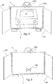
Fig. 3 shows a rear view of a further example of container of the present invention; -
Figs. 4 and5 show further rear views of examples of containers according to the present invention, -
Fig. 6 shows a side view of the variant offig. 5 ; -
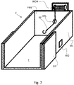
Fig. 7 shows a rear view of a further example of container of the present invention, -
Fig. 8 shows a system for introducing a vehicle into a container receiving area according to any of the previous variants. - The same reference numbers and letters in the figures identify the same elements or components or functions.
- It should be noted that the terms "first", "second", "third", "upper", "lower" and the like can be used here to distinguish various elements. These terms do not imply a spatial, sequential or hierarchical order for the modified elements unless specifically indicated or inferred from the text.
- The elements and features illustrated in the various preferred embodiments, including the drawings, can be combined with each other without however departing from the scope of this application as described below.
- With reference to Figgs. 1 and 2, an example of container C according to the present invention is shown.
- It is specifically adapted for the treatment of damaged vehicles, in particular damaged electrified vehicles.
- The container comprises a bottom F and several perimeter walls WL, FWL, OP, which define a volume A for receiving a damaged vehicle V. The perimeter walls are approximately vertical when the container is in operational conditions, i.e. in conditions of receiving a damaged vehicle. Preferably, the container is open at the top, i.e. without a wall parallel to the bottom F. However, it could also be equipped with a closing roof.
- The container has a longitudinal shape with
- a pair of side walls LWL, parallel to each other,
- a front wall FWL, which when the container is on board a container vehicle TK faces the vehicle cabin and
- a rear wall OP, which defines a closable opening to allow the damaged vehicle to enter and exit the receiving volume A.
- At least one of the side walls LWL of the container is equipped with at least one inspection window WD, which can be closed tightly, to inspect the receiving volume. Advantageously, it is possible to inspect the vehicle with an infrared camera, directly at the position of the relative battery pack.
- Preferably, the inspection window is arranged in a lower half of the side wall and/or in an intermediate position with respect to the longitudinal development of the container.
- The rear wall is formed by a pair of doors each hinged to a respective side wall WL.
- When the doors are not closed, they are arranged to make a seal, so as to allow the flooding of the receiving volume A.
- According to a first preferred variant of the container, see
Figures 3 - 6 , it comprises a first deflection roller DRH arranged approximately on the upper edge of the front wall FWL and a second deflection roller DRL associated in a lower part of the front wall inside of the receiving volume, so as to be able to arrange a tow rope RP between the first and second rollers and to allow a damaged vehicle to be towed inside the receiving volume. - The second roller is arranged in such a way as to allow the vehicle to be towed parallel to the bottom F of the container.
- With reference to
Figure 8 , according to a preferred method for using the container, the same arm AR of the container carrier vehicle TK is used, arranged for the transport of the roll-off container, to move the tow rope. - In particular, the towing rope RP is connected to the arm after the container has been unloaded, therefore a retraction of the arm induces a retraction of the rope. If this is previously connected to a vehicle V, this can be towed inside the receiving volume A.
- This is particularly advantageous, since it is not necessary to electrically feed a winch on board the container.
- According to another variant of the invention, a winch is associated with any point of the container vehicle TK or even a further different vehicle and the tow rope RP is operationally associated with the winch fixed on the container vehicle or further vehicle.
- Generally, for safety reasons, the damaged vehicle is transported to a shelter by means of a tow truck rather than on board the container C. Therefore, a phase in which the damaged vehicle is extracted from the container to be placed on a tow truck must be envisaged. Tow trucks are generally equipped with a winch, therefore, it is possible to use the tow truck winch to introduce the damaged vehicle into the receiving volume, thanks to the two deflection rollers, and to extract it from the receiving volume through the opening of the rear doors OP.
- Alternatively, the container vehicle TK, which must necessarily be present to transport the container C, can cooperate in the towing phases of the damaged vehicle within the receiving volume.
- It is preferable that the rope has a release portion in proximity of the container vehicle so as to be able to move the container vehicle away from the container, in the event of a fire in the container.
- According to another preferred aspect of the invention, the container comprises two or more nozzles J associated with the bottom F of the container arranged to spray the coolant/extinguishing liquid under the damaged vehicle. They are preferably arranged according to a longitudinal and medial alignment of the vehicle.
- Although a single alignment of nozzles is shown in the figures, it is possible to arrange several alignments parallel to each other in order to hit the entire lower part of a damaged vehicle.
- According to a preferred variant which can be combined with any of the previous ones, the container comprises a tank for the coolant/extinguishing liquid arranged under or in the bottom F and communicating with the receiving volume A, so that the sprayed liquid returns falling into the tank and a pump is arranged to take the liquid from the tank and spray it through the two or more nozzles J. In other words, the liquid is recirculated so as to ensure a first cooling of the vehicle battery pack, allowing to postpone the flooding of the container only when this solution appears insufficient.
- Preferably, the bottom F comprises an emerging longitudinal and medial part EP, so as to induce the liquid to be collected at the lateral walls of the container.
- In this regard, it is worth highlighting that the emerging EP part, occupying the volume, helps to limit the quantity of liquid to be introduced into the container when it is necessary to flood the battery pack of the damaged vehicle.
Figure 5 shows, although the doors are open, the insertion of a tube PP to suck up the coolant/extinguishing liquid. Fire brigade vehicles are generally capable of sucking up liquids and are therefore equipped with tanks to contain contaminated liquids, pumps and pipes. - When in a procedure for cooling or extinguishing an electrified vehicle it is necessary to empty the container of the liquid, then a suction pipe PP can be arranged so that its end approaches a perimeter wall. This is particularly advantageous because it allows to easily suck most of the liquid out of the container before pulling the damaged vehicle out of the container.
- From
figure 5 it can be understood that by virtue of the emerging, medial and longitudinal part EP, the liquid is collected along the walls of the container and it makes easier its suction. -
Figure 6 shows a side view of the container ofFigure 5 , in which however the doors OP, which define the rear wall, are closed. -
Figure 7 shows a solution that implements a winch WCH in place of the first deflection roller DRH. - Obviously, this winch needs to be electrically powered. It can be powered by a battery pack associated with the container or associated with the TK container vehicle. According to a preferred method of use of the container, according to
figures 1 - 6 and8 , the following phases are envisaged: - the container vehicle TK with container C on board reaches a damaged vehicle V and positions itself in alignment with the damaged vehicle and suitably spaced,
- if the doors OP of the container are not open they are opened and fixed along the side walls LW of the container,
- the container vehicle TK operates the arm AR to unload the container,
- the tow rope RP is connected to the damaged vehicle V,
- The arm AR of the container vehicle is operated to tow the damaged vehicle inside the receiving volume A of the container,
- The doors OP of the container are closed,
- The phase of monitoring the damaged vehicle begins through at least one of the inspection windows WD, preferably by means of a thermal camera,
- if a rise in the temperature of the battery pack of the damaged vehicle is detected,
- closing the at least one inspection windows and
- introduction of the coolant into the receiving volume.
- The introduction of the liquid, as illustrated above, can be carried out by spraying or nebulization, at least in a first phase in which it is believed that the thermal drift process of the battery system is considered reversible, and/or by flooding the receiving volume.
- Liquid spraying is believed to be particularly efficient when the liquid temperature is relatively low, for example due to the ambient temperature. This avoids the need of flooding the container to immerse the battery pack of the damaged vehicle in the liquid.
- When it is believed that there is no more risk, the coolant can be extracted from the receiving volume. When the liquid introduced into the receiving volume is in a minimum quantity, sprayed under the damaged vehicle, it is not necessary to carry out further operations, since, as detailed above, the liquid returns by gravity to the tank made in the bottom of the container.
- When the liquid introduced into the receiving volume is supplied from outside the container, then it can proceed by immersing a duct PP of a fire brigade vehicle in the receiving volume and sucking the liquid.
- According to a preferred variant of the invention, the container can be equipped with hydraulic connections similar to those described in
EP3263402 to connect a PP duct and to proceed with the evacuation of the liquid from the receiving volume. - It is advantageous to arrange connections along one of the side walls, at the bottom of the container, so as to obtain an easy evacuation of all the liquid.
- Also in this case, the part EP that emerges from the bottom F of the container can help.
- A preferred variant of the invention can provide the emerging part EP from the bottom arranged as in
figures 5 and 6 , without the liquid spraying system and without the winch WCH. - In this case the container is entirely "passive", that is, not electrically powered.
- Implementation variants of the described non-limiting example are possible, without however departing from the scope of protection of the present invention, including all the equivalent embodiments for a person skilled in the art, to the content of the claims.
- From the above description, the person skilled in the art is able to realize the object of the invention without introducing further construction details.
Claims (9)
- A roll-off container (C) for the treatment of damaged vehicles, in particular damaged electrified vehicles, comprising a bottom (F) and several perimeter walls (LWL, FWL, OP) that define a volume (A) for receiving a damaged vehicle (V) and wherein the container has a longitudinal shape with a pair of side walls (LWL), a front wall (FWL) and a rear wall that defines a closable opening (OP) to transfer the vehicle into or out of the volume (A), the container being characterized in that at least one of the side walls (LWL) is equipped with at least one inspection window (WD), which can be closed in a liquid-tight manner.
- Container according to claim 1, wherein the inspection window is arranged in a lower half of the side wall and/or in an intermediate position with respect to the longitudinal development of the container.
- Container according to one of claims 1 or 2, wherein the rear wall is formed by a pair of doors each hinged to a respective side wall (WL).
- Container according to any one of the preceding claims, further comprising a first deflection roller (DRH) arranged approximately on the upper edge of the front wall (FWL) and a second deflection roller (DRL) associated in a lower part of the front wall, inside the volume (A), so as to allow a tow rope (RP) to be arranged to tow a damaged vehicle inside the volume.
- Container according to any one of the preceding claims, comprises two or more nozzles (J) associated with the bottom (F) of the container for spraying the coolant/extinguishing liquid under the damaged vehicle.
- Container according to claim 5, further comprising a coolant/extinguishing liquid tank arranged under or in the bottom (F) and communicating with the receiving volume, so that the sprayed liquid returns to the tank and a pump arranged to withdraw the liquid from the tank and spray it through two or more nozzles (J) associated with the bottom and oriented so as to direct the liquid under the damaged vehicle (V).
- Container according to any one of the preceding claims, wherein the bottom (F) comprises an emerging longitudinal and medial portion, so as to induce the liquid to collect in correspondence with the lateral walls of the container.
- Method of handling a damaged vehicle equipped with a battery system at risk of thermal drift, the method being designed to introduce the vehicle into a roll-off container according to claim 4, the method comprising the step of operating a tow rope (RP) associated with the first deflection roller (DRH) and the second deflection roller (DRL), by means of an arm (B) of a container vehicle arranged to unload the container from the container vehicle after the container is already unloaded.
- A method of handling a damaged vehicle to introduce the vehicle into a roll-off container according to claim 4, the method comprising operating a tow rope (RP) associated with the first deflection roller (DRH) and with the second return roller return (DRL), by means of a winch permanently associated with a tow truck.
Applications Claiming Priority (1)
| Application Number | Priority Date | Filing Date | Title |
|---|---|---|---|
| IT102021000015455A IT202100015455A1 (en) | 2021-06-14 | 2021-06-14 | ROLL-OFF CONTAINER FOR THE TREATMENT OF DAMAGED VEHICLES |
Publications (1)
| Publication Number | Publication Date |
|---|---|
| EP4105078A1 true EP4105078A1 (en) | 2022-12-21 |
Family
ID=77801849
Family Applications (1)
| Application Number | Title | Priority Date | Filing Date |
|---|---|---|---|
| EP22178492.9A Pending EP4105078A1 (en) | 2021-06-14 | 2022-06-10 | Roll-off container for the treatment of damaged vehicles |
Country Status (2)
| Country | Link |
|---|---|
| EP (1) | EP4105078A1 (en) |
| IT (1) | IT202100015455A1 (en) |
Citations (9)
| Publication number | Priority date | Publication date | Assignee | Title |
|---|---|---|---|---|
| US7070002B2 (en) * | 2001-09-19 | 2006-07-04 | Marioff Corporation Oy | Fire extinguishing method and apparatus |
| CN101549784A (en) * | 2009-04-20 | 2009-10-07 | 宁波远成石化电力机械有限公司 | Container windows |
| US20130153314A1 (en) * | 2010-03-01 | 2013-06-20 | Alan Niedzwiecki | Stackable disaster relief vehicle |
| EP3263402A1 (en) | 2016-06-30 | 2018-01-03 | Ellermann Eurocon GmbH | Container for salvaging damaged vehicles and method for salvaging a damaged vehicle |
| CN107720023A (en) * | 2017-10-26 | 2018-02-23 | 无锡杰森表面处理设备有限公司 | The metal counter door of multistage observation window is set |
| CN110371009A (en) * | 2019-06-26 | 2019-10-25 | 江铃汽车股份有限公司 | A kind of road obstacle clearing vehicle |
| DE202020101186U1 (en) * | 2020-03-04 | 2020-06-18 | Schütte Fahrzeugbau Gesellschaft mit beschränkter Haftung | Device for removing a damaged electric vehicle |
| CN111991728A (en) * | 2020-09-07 | 2020-11-27 | 中国科学技术大学 | Energy storage prefabricated cabin for lithium battery fire and fire fighting tests |
| BR202019022713U2 (en) * | 2019-10-30 | 2021-05-11 | Mauro Renato Souza Da Rosa | constructive arrangement in a storage box adaptable to vehicles with bucket |
-
2021
- 2021-06-14 IT IT102021000015455A patent/IT202100015455A1/en unknown
-
2022
- 2022-06-10 EP EP22178492.9A patent/EP4105078A1/en active Pending
Patent Citations (9)
| Publication number | Priority date | Publication date | Assignee | Title |
|---|---|---|---|---|
| US7070002B2 (en) * | 2001-09-19 | 2006-07-04 | Marioff Corporation Oy | Fire extinguishing method and apparatus |
| CN101549784A (en) * | 2009-04-20 | 2009-10-07 | 宁波远成石化电力机械有限公司 | Container windows |
| US20130153314A1 (en) * | 2010-03-01 | 2013-06-20 | Alan Niedzwiecki | Stackable disaster relief vehicle |
| EP3263402A1 (en) | 2016-06-30 | 2018-01-03 | Ellermann Eurocon GmbH | Container for salvaging damaged vehicles and method for salvaging a damaged vehicle |
| CN107720023A (en) * | 2017-10-26 | 2018-02-23 | 无锡杰森表面处理设备有限公司 | The metal counter door of multistage observation window is set |
| CN110371009A (en) * | 2019-06-26 | 2019-10-25 | 江铃汽车股份有限公司 | A kind of road obstacle clearing vehicle |
| BR202019022713U2 (en) * | 2019-10-30 | 2021-05-11 | Mauro Renato Souza Da Rosa | constructive arrangement in a storage box adaptable to vehicles with bucket |
| DE202020101186U1 (en) * | 2020-03-04 | 2020-06-18 | Schütte Fahrzeugbau Gesellschaft mit beschränkter Haftung | Device for removing a damaged electric vehicle |
| CN111991728A (en) * | 2020-09-07 | 2020-11-27 | 中国科学技术大学 | Energy storage prefabricated cabin for lithium battery fire and fire fighting tests |
Also Published As
| Publication number | Publication date |
|---|---|
| IT202100015455A1 (en) | 2022-12-14 |
Similar Documents
| Publication | Publication Date | Title |
|---|---|---|
| EP4011459A1 (en) | Transport and storage container for hv batteries and / or electric vehicles | |
| DE202019104504U1 (en) | Container for holding dangerous goods | |
| DE102019127014A1 (en) | Tub-shaped container for holding HV batteries and / or e-vehicles | |
| WO2022017979A1 (en) | Battery arrangement, motor vehicle and method for flooding a high-voltage battery | |
| EP4104906B1 (en) | Depot and arrangement for storing a vehicle | |
| CN108215977A (en) | It dies of illness and animals with diseases harmless treatment Special carrier loader | |
| EP2670238B1 (en) | Cooling system, especially for cryopreserving biological samples, comprising devices for use in case of an emergency | |
| DE202021103253U1 (en) | Depot for storing a vehicle | |
| DE102018129262B4 (en) | Device and fire protection device with safety cover for vehicles | |
| JP2024127915A (en) | Unmanned Verification System and Method | |
| DE102021102402A1 (en) | Container, vehicle and method for salvaging damaged vehicles, in particular damaged electric vehicles | |
| CN208948055U (en) | Frozen products insulated container | |
| EP3326960B1 (en) | Basket system for work of operators on shipping containers on ships | |
| IT202100015455A1 (en) | ROLL-OFF CONTAINER FOR THE TREATMENT OF DAMAGED VEHICLES | |
| KR101772873B1 (en) | Carrier vehicle for collection dust prevention device is equipped with a scattering of dust emissions | |
| ES3040438T3 (en) | Exchangeable container body, in particular of the swap body type, and transport container for electrically powered tractive vehicles with associated battery compartment | |
| CN103771046B (en) | A kind of quick freezing and cold preserving shelter | |
| EP4105077B1 (en) | Roll-off container for the treatment of damaged vehicles | |
| FR3131219A3 (en) | Intervention dumpster for dangerous and/or flammable objects, in particular an electric vehicle in distress | |
| US20240140698A1 (en) | Containment unit | |
| CN213087022U (en) | Emergency disposal pool for leakage of dangerous cargo container and emergency disposal site thereof | |
| CN214006917U (en) | Emergency door system of power station and power station | |
| CN109160118A (en) | Frozen products insulated container | |
| CN212195668U (en) | Freight train box body for logistics transportation | |
| FR2667898A1 (en) | Lock chamber for exchange |
Legal Events
| Date | Code | Title | Description |
|---|---|---|---|
| PUAI | Public reference made under article 153(3) epc to a published international application that has entered the european phase |
Free format text: ORIGINAL CODE: 0009012 |
|
| STAA | Information on the status of an ep patent application or granted ep patent |
Free format text: STATUS: THE APPLICATION HAS BEEN PUBLISHED |
|
| AK | Designated contracting states |
Kind code of ref document: A1 Designated state(s): AL AT BE BG CH CY CZ DE DK EE ES FI FR GB GR HR HU IE IS IT LI LT LU LV MC MK MT NL NO PL PT RO RS SE SI SK SM TR |
|
| STAA | Information on the status of an ep patent application or granted ep patent |
Free format text: STATUS: REQUEST FOR EXAMINATION WAS MADE |
|
| 17P | Request for examination filed |
Effective date: 20230607 |
|
| RBV | Designated contracting states (corrected) |
Designated state(s): AL AT BE BG CH CY CZ DE DK EE ES FI FR GB GR HR HU IE IS IT LI LT LU LV MC MK MT NL NO PL PT RO RS SE SI SK SM TR |
|
| STAA | Information on the status of an ep patent application or granted ep patent |
Free format text: STATUS: EXAMINATION IS IN PROGRESS |
|
| 17Q | First examination report despatched |
Effective date: 20240514 |