EP4103500B1 - Device for storing a sheet pile in a converting machine and corresponding converting machine - Google Patents
Device for storing a sheet pile in a converting machine and corresponding converting machine Download PDFInfo
- Publication number
- EP4103500B1 EP4103500B1 EP21702112.0A EP21702112A EP4103500B1 EP 4103500 B1 EP4103500 B1 EP 4103500B1 EP 21702112 A EP21702112 A EP 21702112A EP 4103500 B1 EP4103500 B1 EP 4103500B1
- Authority
- EP
- European Patent Office
- Prior art keywords
- sampling plate
- jogger
- sampling
- sheets
- converting machine
- Prior art date
- Legal status (The legal status is an assumption and is not a legal conclusion. Google has not performed a legal analysis and makes no representation as to the accuracy of the status listed.)
- Active
Links
Images




Classifications
-
- B—PERFORMING OPERATIONS; TRANSPORTING
- B65—CONVEYING; PACKING; STORING; HANDLING THIN OR FILAMENTARY MATERIAL
- B65H—HANDLING THIN OR FILAMENTARY MATERIAL, e.g. SHEETS, WEBS, CABLES
- B65H31/00—Pile receivers
-
- B—PERFORMING OPERATIONS; TRANSPORTING
- B65—CONVEYING; PACKING; STORING; HANDLING THIN OR FILAMENTARY MATERIAL
- B65H—HANDLING THIN OR FILAMENTARY MATERIAL, e.g. SHEETS, WEBS, CABLES
- B65H29/00—Delivering or advancing articles from machines; Advancing articles to or into piles
- B65H29/58—Article switches or diverters
- B65H29/585—Article switches or diverters taking samples from the main stream
-
- B—PERFORMING OPERATIONS; TRANSPORTING
- B41—PRINTING; LINING MACHINES; TYPEWRITERS; STAMPS
- B41F—PRINTING MACHINES OR PRESSES
- B41F1/00—Platen presses, i.e. presses in which printing is effected by at least one essentially-flat pressure-applying member co-operating with a flat type-bed
- B41F1/10—Platen presses, i.e. presses in which printing is effected by at least one essentially-flat pressure-applying member co-operating with a flat type-bed for multi-impression printing in one or more colours, e.g. on webs
- B41F1/12—Platen presses, i.e. presses in which printing is effected by at least one essentially-flat pressure-applying member co-operating with a flat type-bed for multi-impression printing in one or more colours, e.g. on webs on sheets
-
- B—PERFORMING OPERATIONS; TRANSPORTING
- B41—PRINTING; LINING MACHINES; TYPEWRITERS; STAMPS
- B41F—PRINTING MACHINES OR PRESSES
- B41F1/00—Platen presses, i.e. presses in which printing is effected by at least one essentially-flat pressure-applying member co-operating with a flat type-bed
- B41F1/24—Platen presses, i.e. presses in which printing is effected by at least one essentially-flat pressure-applying member co-operating with a flat type-bed specially adapted for proof printing
-
- B—PERFORMING OPERATIONS; TRANSPORTING
- B41—PRINTING; LINING MACHINES; TYPEWRITERS; STAMPS
- B41F—PRINTING MACHINES OR PRESSES
- B41F1/00—Platen presses, i.e. presses in which printing is effected by at least one essentially-flat pressure-applying member co-operating with a flat type-bed
- B41F1/26—Details
- B41F1/28—Sheet-conveying, -aligning or -clamping devices
-
- B—PERFORMING OPERATIONS; TRANSPORTING
- B41—PRINTING; LINING MACHINES; TYPEWRITERS; STAMPS
- B41F—PRINTING MACHINES OR PRESSES
- B41F1/00—Platen presses, i.e. presses in which printing is effected by at least one essentially-flat pressure-applying member co-operating with a flat type-bed
- B41F1/26—Details
- B41F1/56—Auxiliary devices
- B41F1/58—Arrangements of counting devices for counting sheets
-
- B—PERFORMING OPERATIONS; TRANSPORTING
- B41—PRINTING; LINING MACHINES; TYPEWRITERS; STAMPS
- B41F—PRINTING MACHINES OR PRESSES
- B41F19/00—Apparatus or machines for carrying out printing operations combined with other operations
- B41F19/02—Apparatus or machines for carrying out printing operations combined with other operations with embossing
- B41F19/06—Printing and embossing between a negative and a positive forme after inking and wiping the negative forme; Printing from an ink band treated with colour or "gold"
- B41F19/064—Presses of the reciprocating type
- B41F19/068—Presses of the reciprocating type motor-driven
-
- B—PERFORMING OPERATIONS; TRANSPORTING
- B41—PRINTING; LINING MACHINES; TYPEWRITERS; STAMPS
- B41F—PRINTING MACHINES OR PRESSES
- B41F33/00—Indicating, counting, warning, control or safety devices
- B41F33/0036—Devices for scanning or checking the printed matter for quality control
-
- B—PERFORMING OPERATIONS; TRANSPORTING
- B41—PRINTING; LINING MACHINES; TYPEWRITERS; STAMPS
- B41F—PRINTING MACHINES OR PRESSES
- B41F33/00—Indicating, counting, warning, control or safety devices
- B41F33/02—Arrangements of indicating devices, e.g. counters
-
- B—PERFORMING OPERATIONS; TRANSPORTING
- B65—CONVEYING; PACKING; STORING; HANDLING THIN OR FILAMENTARY MATERIAL
- B65H—HANDLING THIN OR FILAMENTARY MATERIAL, e.g. SHEETS, WEBS, CABLES
- B65H29/00—Delivering or advancing articles from machines; Advancing articles to or into piles
- B65H29/02—Delivering or advancing articles from machines; Advancing articles to or into piles by mechanical grippers engaging the leading edge only of the articles
- B65H29/04—Delivering or advancing articles from machines; Advancing articles to or into piles by mechanical grippers engaging the leading edge only of the articles the grippers being carried by endless chains or bands
- B65H29/041—Delivering or advancing articles from machines; Advancing articles to or into piles by mechanical grippers engaging the leading edge only of the articles the grippers being carried by endless chains or bands and introducing into a pile
-
- B—PERFORMING OPERATIONS; TRANSPORTING
- B65—CONVEYING; PACKING; STORING; HANDLING THIN OR FILAMENTARY MATERIAL
- B65H—HANDLING THIN OR FILAMENTARY MATERIAL, e.g. SHEETS, WEBS, CABLES
- B65H29/00—Delivering or advancing articles from machines; Advancing articles to or into piles
- B65H29/02—Delivering or advancing articles from machines; Advancing articles to or into piles by mechanical grippers engaging the leading edge only of the articles
- B65H29/04—Delivering or advancing articles from machines; Advancing articles to or into piles by mechanical grippers engaging the leading edge only of the articles the grippers being carried by endless chains or bands
- B65H29/042—Intermediate conveyors, e.g. transferring devices
- B65H29/044—Intermediate conveyors, e.g. transferring devices conveying through a machine
-
- B—PERFORMING OPERATIONS; TRANSPORTING
- B65—CONVEYING; PACKING; STORING; HANDLING THIN OR FILAMENTARY MATERIAL
- B65H—HANDLING THIN OR FILAMENTARY MATERIAL, e.g. SHEETS, WEBS, CABLES
- B65H31/00—Pile receivers
- B65H31/24—Pile receivers multiple or compartmented, e.d. for alternate, programmed, or selective filling
-
- B—PERFORMING OPERATIONS; TRANSPORTING
- B65—CONVEYING; PACKING; STORING; HANDLING THIN OR FILAMENTARY MATERIAL
- B65H—HANDLING THIN OR FILAMENTARY MATERIAL, e.g. SHEETS, WEBS, CABLES
- B65H31/00—Pile receivers
- B65H31/34—Apparatus for squaring-up piled articles
- B65H31/38—Apparatus for vibrating or knocking the pile during piling
-
- B—PERFORMING OPERATIONS; TRANSPORTING
- B65—CONVEYING; PACKING; STORING; HANDLING THIN OR FILAMENTARY MATERIAL
- B65H—HANDLING THIN OR FILAMENTARY MATERIAL, e.g. SHEETS, WEBS, CABLES
- B65H2301/00—Handling processes for sheets or webs
- B65H2301/50—Auxiliary process performed during handling process
- B65H2301/54—Auxiliary process performed during handling process for managing processing of handled material
- B65H2301/542—Quality control
- B65H2301/5421—Quality control taking samples
-
- B—PERFORMING OPERATIONS; TRANSPORTING
- B65—CONVEYING; PACKING; STORING; HANDLING THIN OR FILAMENTARY MATERIAL
- B65H—HANDLING THIN OR FILAMENTARY MATERIAL, e.g. SHEETS, WEBS, CABLES
- B65H2402/00—Constructional details of the handling apparatus
- B65H2402/40—Details of frames, housings or mountings of the whole handling apparatus
- B65H2402/44—Housings
- B65H2402/441—Housings movable for facilitating access to area inside the housing, e.g. pivoting or sliding
-
- B—PERFORMING OPERATIONS; TRANSPORTING
- B65—CONVEYING; PACKING; STORING; HANDLING THIN OR FILAMENTARY MATERIAL
- B65H—HANDLING THIN OR FILAMENTARY MATERIAL, e.g. SHEETS, WEBS, CABLES
- B65H2405/00—Parts for holding the handled material
- B65H2405/10—Cassettes, holders, bins, decks, trays, supports or magazines for sheets stacked substantially horizontally
- B65H2405/12—Parts to be handled by user
-
- B—PERFORMING OPERATIONS; TRANSPORTING
- B65—CONVEYING; PACKING; STORING; HANDLING THIN OR FILAMENTARY MATERIAL
- B65H—HANDLING THIN OR FILAMENTARY MATERIAL, e.g. SHEETS, WEBS, CABLES
- B65H2405/00—Parts for holding the handled material
- B65H2405/30—Other features of supports for sheets
- B65H2405/32—Supports for sheets partially insertable - extractable, e.g. upon sliding movement, drawer
- B65H2405/324—Supports for sheets partially insertable - extractable, e.g. upon sliding movement, drawer between operative position and non operative position
-
- B—PERFORMING OPERATIONS; TRANSPORTING
- B65—CONVEYING; PACKING; STORING; HANDLING THIN OR FILAMENTARY MATERIAL
- B65H—HANDLING THIN OR FILAMENTARY MATERIAL, e.g. SHEETS, WEBS, CABLES
- B65H2407/00—Means not provided for in groups B65H2220/00 – B65H2406/00 specially adapted for particular purposes
- B65H2407/20—Means not provided for in groups B65H2220/00 – B65H2406/00 specially adapted for particular purposes for manual intervention of operator
-
- B—PERFORMING OPERATIONS; TRANSPORTING
- B65—CONVEYING; PACKING; STORING; HANDLING THIN OR FILAMENTARY MATERIAL
- B65H—HANDLING THIN OR FILAMENTARY MATERIAL, e.g. SHEETS, WEBS, CABLES
- B65H2407/00—Means not provided for in groups B65H2220/00 – B65H2406/00 specially adapted for particular purposes
- B65H2407/20—Means not provided for in groups B65H2220/00 – B65H2406/00 specially adapted for particular purposes for manual intervention of operator
- B65H2407/22—Means not provided for in groups B65H2220/00 – B65H2406/00 specially adapted for particular purposes for manual intervention of operator means for observing the handled material during its handling
-
- B—PERFORMING OPERATIONS; TRANSPORTING
- B65—CONVEYING; PACKING; STORING; HANDLING THIN OR FILAMENTARY MATERIAL
- B65H—HANDLING THIN OR FILAMENTARY MATERIAL, e.g. SHEETS, WEBS, CABLES
- B65H2801/00—Application field
- B65H2801/42—Die-cutting
Definitions
- converting machines can have mechanisms for temporarily creating an access to the piling area such that an operator can manually pick sample sheets from the pile of produced sheets.
- sampling devices in converting machines are described in DE 553 079 C , DE196 122 80 A1 , DE 10 2020 19221434 A1 and US 3 966 195 A1 .
- the object of the invention is solved by a device for storing a sheet pile in a converting machine wherein the device comprises a transfer mechanism for delivering sheets into a piling area of the device, and a sampling plate which is adjustable between a sampling position and an access position, wherein the top of the piling area is covered by the sampling plate when the sampling plate is in the sampling position so that the sheets delivered by the transfer mechanism are collected by the sampling plate, and wherein the top of the piling area is free when the sampling plate is in the access position.
- the piling area is covered here has the meaning of the sampling plate being arranged above the piling area so that sheets delivered by the transfer mechanism cannot reach the piling area anymore but are rather collected by the sampling plate.
- the sampling plate especially completely covers the top of the piling area.
- the sheets are subjected to one or more converting operations by the converting machine, e.g. printing, cutting, creasing, stamping and/or folding-gluing and are fed by the converting machine by means of the transfer mechanism to the piling area.
- the converting machine e.g. printing, cutting, creasing, stamping and/or folding-gluing
- the transfer mechanism can be the same transfer mechanism used in the overall converting machine or be connected to an additional converting machine transfer mechanism.
- the sheets are stacked in a vertical pile in the piling area of the device as long as the sampling plate is in the access position. If the sampling plate is in the sampling position, the sheets produced by the converting machine are collected on the sampling plate instead.
- the sampling plate is parallel to the sheets in the sheet pile so that further sheets produced by the converting machine can be placed on the sampling plate in the same manner as they would be stacked on the sheet pile.
- the sheets can be made out of cardboard, paper, foil or a composite material.
- the device according to the invention allows for collecting sample sheets in an easy manner by adjusting the position of the sampling plate.
- the at least one sample sheet on the sampling plate can afterwards be collected and checked for its quality.
- the sampling plate can be adjusted from the access position into the sampling position manually and/or by a drive.
- the sampling plate at least partially extends outside of a housing of the device when being in the access position.
- the sampling plate at least partially extends out of the converting machine to allow the operator to easily pick up the sheets collected by the sampling plate without the need for an access to inner parts of the converting machine.
- the sampling plate is removably engagable with an opening of the housing. In this way, it is possible to insert the sampling plate into the device only when needed, i.e. when sheets need to be collected.
- the sampling plate comprises several segments which can be at least partially folded against each other. This allows for non-linear movements of the sampling plate when being adjusted between the sampling position and the access position.
- the guide rail ensures a controlled movement of the sampling plate when the sampling plate is adjusted to the sampling position.
- the device comprises two guide rails at opposite side boundaries of the piling area. In this way, the movement of the sampling plate is further secured and shifting and tilting of the sampling plate is prevented.
- the one or more guide rails especially extend from the housing of the device over the full length of the respective side boundary of the piling area.
- the device comprises a jogger which is arranged between the sampling plate and a front boundary of the piling area when the sampling plate is in the access position.
- the front boundary of the piling area especially is perpendicular to the side boundary of the piling area.
- the lateral jogger is also used to align the sheets in the sheet pile when and/or after they are and/or have been delivered by the transfer mechanism.
- the lateral jogger can be tilted back and forth towards and away from the side boundary of the piling area.
- the jogger and/or the lateral jogger prevents the sampling plate from accidentally blocking the piling area.
- the device can comprise a sensor adapted for monitoring the position of the sampling plate.
- the object of the invention is further solved by a converting machine comprising a device as described before.
- Figure 1 shows a converting machine 10 according to the invention.
- the converting machine 10 is composed of several modules which are arranged one after another.
- the converting machine 10 comprises a loading station 12, a feeder 14, a converting station 16, a discharge station 18, and a device 20 according to the invention.
- the converting machine 10 has a running direction R which is defined by the direction in which sheets are being processed.
- the loading station 12 is used for supplying the converting machine 10 with raw sheets to be processed.
- the raw sheets can be made out of cardbox, paper or plastic.
- the transfer mechanism 28 comprises several gripper bars 30 which take turns to grip a sheet 22 at its front edge and to pull the sheet 22 through the stations of the converting machine 10.
- the device 20 has a display unit 46 with a display 48 and control elements 50.
- the display 48 can also be a touch-sensitive display.
- the control elements 50 can be incorporated into the display 48.
- the display unit 46 can be used by an operator to control the device 20, preferably to control all modules of the converting machine 10.
- Figure 2 shows a perspective view of parts of the device 20.
Landscapes
- Engineering & Computer Science (AREA)
- Mechanical Engineering (AREA)
- Quality & Reliability (AREA)
- Pile Receivers (AREA)
- Making Paper Articles (AREA)
- Unwinding Webs (AREA)
- Sheets, Magazines, And Separation Thereof (AREA)
- Computer And Data Communications (AREA)
Description
- The invention relates to a device for storing a sheet pile in a converting machine and a converting machine.
- Converting machines are used in the packaging industry for processing raw materials, e.g. cardboard, paper or foils, into intermediate or finished products, typically in the form of sheets. Converting operations can be printing, cutting, creasing, stamping and/or folding-gluing. Accordingly, the term converting machine here also generally means sheet processing machine. The sheets can be collected in vertical stacks after converting in a designated piling area of the converting machine.
- In order to control the quality of the produced sheets, it is necessary to regularly collect sample sheets during operation of the converting machine. For this purpose, converting machines can have mechanisms for temporarily creating an access to the piling area such that an operator can manually pick sample sheets from the pile of produced sheets.
- Examples here for are known for example
US 2007/102875 A1 showing a device for conveying sheetlike articles, in particular printed sheets, by which conveyed sheetlike articles may optionally be fed to various conveying routes, various delivery stacks being provided in particular at the end of the conveying routes. At least one conveying module is designed as a mechanical switch point in order to reroute a conveyed sheetlike article in its conveying route. - Other examples for sampling devices in converting machines are described in
DE 553 079 C ,DE196 122 80 A1 ,DE 10 2020 19221434 A1 US 3 966 195 A1 . - However, to ensure a controlled and safe access for the operator, known mechanisms need redundant security systems which restrict the available space for the operator and/or necessitate the converting machine to stop the sheet production for extended periods of time.
- The object of the invention is to provide a device which allows for an easier collection of sample sheets in a converting machine. Preferably, the device allows reducing the downtime of a converting machine.
- The object of the invention is solved by a device for storing a sheet pile in a converting machine wherein the device comprises a transfer mechanism for delivering sheets into a piling area of the device, and a sampling plate which is adjustable between a sampling position and an access position, wherein the top of the piling area is covered by the sampling plate when the sampling plate is in the sampling position so that the sheets delivered by the transfer mechanism are collected by the sampling plate, and wherein the top of the piling area is free when the sampling plate is in the access position.
- The expression "the piling area is covered" here has the meaning of the sampling plate being arranged above the piling area so that sheets delivered by the transfer mechanism cannot reach the piling area anymore but are rather collected by the sampling plate.
- The sampling plate especially completely covers the top of the piling area.
- The sheets are subjected to one or more converting operations by the converting machine, e.g. printing, cutting, creasing, stamping and/or folding-gluing and are fed by the converting machine by means of the transfer mechanism to the piling area.
- The transfer mechanism can be the same transfer mechanism used in the overall converting machine or be connected to an additional converting machine transfer mechanism.
- During operation of the converting machine, the sheets are stacked in a vertical pile in the piling area of the device as long as the sampling plate is in the access position. If the sampling plate is in the sampling position, the sheets produced by the converting machine are collected on the sampling plate instead.
- Preferably, in the sampling position, the sampling plate is parallel to the sheets in the sheet pile so that further sheets produced by the converting machine can be placed on the sampling plate in the same manner as they would be stacked on the sheet pile.
- The sheets can be made out of cardboard, paper, foil or a composite material.
- The device according to the invention allows for collecting sample sheets in an easy manner by adjusting the position of the sampling plate. The at least one sample sheet on the sampling plate can afterwards be collected and checked for its quality.
- Preferably, an operator can reach the sampling plate for collecting the sheets when the sampling plate is in the access position while the converting machine is in operating mode, i.e. processes sheets. In this way, the downtime of the converting machine is reduced.
- The sampling plate can be adjusted from the access position into the sampling position manually and/or by a drive.
- According to the invention, the sampling plate at least partially extends outside of a housing of the device when being in the access position.
- The housing of the device can be the housing of the converting machine, too.
- With other words, the sampling plate at least partially extends out of the converting machine to allow the operator to easily pick up the sheets collected by the sampling plate without the need for an access to inner parts of the converting machine.
- In another variant, the sampling plate is removably engagable with an opening of the housing. In this way, it is possible to insert the sampling plate into the device only when needed, i.e. when sheets need to be collected.
- The sampling plate can have a folding edge to flip over the part of the sampling plate which extends from the housing. This allows for a more compact storage of the sampling plate when it is not needed to collect sheets.
- In another variant, the sampling plate comprises several segments which can be at least partially folded against each other. This allows for non-linear movements of the sampling plate when being adjusted between the sampling position and the access position.
- The device preferably comprises a guide rail extending at least partially along a side boundary of the piling area and along which the sampling plate moves when being adjusted between the access position and the sampling position.
- At least the part of the guide rail which extends along the side boundary of the piling area can be parallel to the sheets of the sheet pile.
- The guide rail ensures a controlled movement of the sampling plate when the sampling plate is adjusted to the sampling position.
- Preferably, the device comprises two guide rails at opposite side boundaries of the piling area. In this way, the movement of the sampling plate is further secured and shifting and tilting of the sampling plate is prevented.
- The one or more guide rails especially extend from the housing of the device over the full length of the respective side boundary of the piling area.
- Preferably, the device comprises a jogger which is arranged between the sampling plate and a front boundary of the piling area when the sampling plate is in the access position.
- The jogger is used to align the sheets in the sheet pile when and/or after they are and/or have been delivered by the transfer mechanism. For this purpose, the jogger can be tilted back and forth towards and away from the front boundary of the piling area so that the sheets in the piling area are aligned to each other.
- The front boundary of the piling area especially is perpendicular to the side boundary of the piling area.
- The jogger especially extends over the full length of the front boundary of the piling area.
- Further, the device can comprise at least one lateral jogger arranged at the side boundary of the piling area.
- The lateral jogger is also used to align the sheets in the sheet pile when and/or after they are and/or have been delivered by the transfer mechanism. For this purpose, the lateral jogger can be tilted back and forth towards and away from the side boundary of the piling area.
- The device can comprise several lateral joggers, especially at least one lateral jogger at both side boundaries of the piling area.
- The lateral jogger can extends over the full length of the side boundary of the piling area.
- In one embodiment, the jogger and/or the at least one lateral jogger can be adjusted between a working position and a clearing position by a drive element, wherein the sampling plate can be adjusted into the sampling position only when the jogger and/or the at least one lateral jogger is/are in the clearing position.
- In this embodiment, the jogger and/or the lateral jogger do not need to be mounted such that they are at all times below or above the level on which the sampling plate is moved over the piling area. This allows for reducing the necessary size of the device.
- At the same time, the jogger and/or the lateral jogger prevents the sampling plate from accidentally blocking the piling area.
- The drive element can comprise a piston which can be driven electrically, pneumatically and/or hydraulically.
- The device can comprise a sensor adapted for monitoring the position of the sampling plate.
- The sensor is especially located between the housing of the device and the piling area, preferably between the housing of the device and the jogger.
- The sensor allows to determine if the sampling plate is moved out of the access position. In this case, the jogger and/or the one or more lateral joggers can be automatically adjusted into the clearing position.
- The sensor can be a light barrier.
- The object of the invention is further solved by a converting machine comprising a device as described before.
- Further advantages and features will become apparent from the following description of the invention and from the appended figures which show a nonlimiting exemplary embodiment of the invention and in which:
-
Figure 1 shows a schematic converting machine comprising a device according to the invention; -
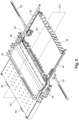
Figure 2 shows a perspective view of parts of the device ofFigure 1 with a sampling plate in an access position; -
Figure 3 shows a perspective view of the jogger of the device ofFigure 1 ; -
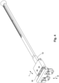
Figure 4 shows a perspective view of a lateral jogger of the device ofFigure 1 ; -
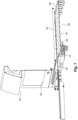
Figure 5 shows a cross-section of a detail of the lateral jogger ofFigure 4 ; -
Figure 6 shows a perspective view of a cross-section of the device ofFigure 2 along plane A-A with the sampling plate in the access position; and -
Figure 7 shows a perspective view of a cross-section of the device ofFigure 2 along plane A-A with the sampling plate in a sampling position. -
Figure 1 shows a convertingmachine 10 according to the invention. The convertingmachine 10 is composed of several modules which are arranged one after another. In the shown embodiment, the convertingmachine 10 comprises aloading station 12, afeeder 14, a convertingstation 16, adischarge station 18, and adevice 20 according to the invention. - The converting
machine 10 has a running direction R which is defined by the direction in which sheets are being processed. - The
loading station 12 is used for supplying the convertingmachine 10 with raw sheets to be processed. The raw sheets can be made out of cardbox, paper or plastic. - The individual raw sheets are taken out of the
loading station 12 by thefeeder 14 and fed into the convertingstation 16. - The converting
station 16 can be a cutting station, an embossing station or a stamping station. In the shown embodiment, the converting machine comprises aplaten press 24. In the convertingstation 16, the raw sheets are converted tosheets 22. - The
discharge station 18 is used to transfer thesheets 22 from the convertingstation 16 to apiling area 26 of thedevice 20. Thedischarge station 18 can also be used to ensure correct alignment of thesheets 22. - The
sheets 22 are moved along the running direction R by atransfer mechanism 28. Thetransfer mechanism 28 is adapted to individually transfer eachsingle sheet 22 from thefeeder 14 to thedevice 20. - The
transfer mechanism 28 comprisesseveral gripper bars 30 which take turns to grip asheet 22 at its front edge and to pull thesheet 22 through the stations of the convertingmachine 10. - The gripper bars 30 are connected to a
chain 32 which is moving in a closed circle. Thechain 32 moves in a step-wise manner, whereby with each step thesheet 22 is moved to the next station of the convertingmachine 10. - In the
device 20, thesheets 22 are released from thetransfer mechanism 28 to form a pile of sheets in the pilingarea 26, e.g. on apallet 34. - Accordingly, in the shown embodiment, only a
single transfer mechanism 28 is used for all modules of the convertingmachine 10, including thedevice 20. Generally, thedevice 20 could comprise itsown transfer mechanism 28 which is connected to a further converting machine transfer mechanism. - At a
front boundary 36 of the pilingarea 26, ajogger 38 is arranged. Thejogger 38 is used to align the processedsheets 22 along the running direction R in the pilingarea 26. This is done by providing a flat surface by thejogger 38 against which thesheets 22 can be pushed when delivered into the pilingarea 26 by thetransfer mechanism 28. - Further, the
device 20 comprises aback jogger 39 which is arranged at a back side of the pilingarea 26 opposite to the front side of the pilingarea 26. Accordingly, theback jogger 39 is arranged opposite to thejogger 38. - Further, the
jogger 38 can tilt back and forth to align thesheets 22 in the pilingarea 26. - The
device 20 comprises ahousing 40 which in the shown embodiment is also part of the housing of the convertingmachine 10. - The
housing 40 comprises awindow 42 so that an operator of the convertingmachine 10 can look into the convertingmachine 10, especially on thesheets 22 in the pilingarea 26. - The
housing 40 further has anopening 43 through which asampling plate 44 partially extends outwards from thehousing 40. Thesampling plate 44 further compriseshandles 45 which can be used by the operator to adjust the position of thesampling plate 44. - Additionally, the
device 20 has adisplay unit 46 with adisplay 48 andcontrol elements 50. Thedisplay 48 can also be a touch-sensitive display. In this case, thecontrol elements 50 can be incorporated into thedisplay 48. Thedisplay unit 46 can be used by an operator to control thedevice 20, preferably to control all modules of the convertingmachine 10. -
Figure 2 shows a perspective view of parts of thedevice 20. - The
jogger 38 and theback jogger 39 extend essentially over the full length of the front and back surface of the pilingarea 26, respectively. - As can be seen from
Figure 2 , additionally to thejogger 38 and theback jogger 39, thedevice 20 further comprises twolateral joggers 52. Thelateral joggers 52 are arranged at side surfaces of the pilingarea 26, wherein each of the twolateral joggers 52 are arranged opposing each other at opposite side surfaces of the pilingarea 26. - The
device 20 further comprises twoguide rails 54, each one extending along one of the side boundaries of the pilingarea 26. The guide rails 54 further partially extend outwards of thehousing 40. - The
sampling plate 44 is arranged on the guide rails 54. - In
Figures 1 and2 , thesampling plate 44 is in an access position. In the access position, the top of the pilingarea 26 is free so thatsheets 22 can be transferred by thetransfer mechanism 28 to the pilingarea 26 to form a sheet pile. - Additionally, the
jogger 38 is arranged at a height such that thesampling plate 44 cannot slide along the guide rails 54 over the pilingarea 26, i.e. thejogger 38 blocks the movement of thesampling plate 44. This position of thejogger 38 is termed working position. - The
device 20 further comprises asensor 55 which can detect the position of thesampling plate 44. Thesensor 55 can be a light barrier. -
Figure 3 shows a perspective view of thejogger 38 in more detail. As illustrated inFigure 3 by double-arrow J, thejogger 38 can be moved back and forth towards and from the pilingarea 26. - Additionally, the
jogger 38 can be moved up and down as illustrated by double-arrow K inFigure 3 to switch from the working position into a sampling position in which thejogger 38 no longer blocks the movement of thesampling plate 44 along the guide rails 54. - The
jogger 38 can be moved along directions J and K bydrive elements 56 which are cylinders with electrically driven pistons. Thejogger 38 can also haveseparate drive elements 56 for the respective motions along directions J and K. -
Figure 4 shows one of thelateral joggers 52 in more detail. Thelateral jogger 52 can be moved sideways along the directions illustrated by double-arrow L and up and down along the directions illustrated by double-arrow M. -
Figure 5 shows a cross-section along the center of the extension direction of thelateral jogger 52 ofFigure 4 . - The
drive element 56 of thelateral jogger 52 comprises twocylinders piston 62 moving along the direction L and a second one with apiston 64 moving along the direction M. Thepistons pistons - The
lateral joggers 52 also can be adjusted into a working position in which the movement of thesampling plate 44 along the guide rails 54 is blocked by thelateral joggers 52 and into a sampling position in which thelateral jogger 52 no longer blocks the movement of thesampling plate 38 along the guide rails 54. - In the following, the mode of operation of the
device 20 will be described with reference toFigures 6 and7 which show perspective views of a cross-section along plane A-A shown inFigure 2 . - During default operation of the converting
machine 10,sheets 22 will be processed and delivered by thetransfer mechanism 28 to the pilingarea 26. - The
jogger 38, theback jogger 39 and thelateral joggers 52 are used to align thesheets 22 delivered to the pilingarea 26. - The
sampling plate 44 is in the access position in which it partially extends from thehousing 40 outwards. Accordingly, thesampling plate 44 is outside of the path of thesheets 22 towards the pilingarea 26. - The operator of the converting
machine 10 can observe thesheets 22 arriving at the pilingarea 26 through thewindow 42. If the operator decides to take sample sheets, e.g. for checking the quality of the processedsheets 22, he can start a sampling procedure by pressing a sampling button which is one of thecontrol elements 50 of thedisplay unit 46. - This stops the
transfer mechanism 28 from deliveringnew sheets 22 to the pilingarea 26 for a pre-selected time period t1, e.g. for 1 to 3 seconds. - Further, the
jogger 38 and thelateral joggers 52 are moved downwards into their sampling positions by theirrespective drive elements 56 so that the guide rails 54 are no longer blocked. - Then, the
display unit 46 gives the operator a signal that thesampling plate 44 can be moved into the sampling position. The signal can be given visually on thedisplay 48 or acoustically by means of a (not shown) loudspeaker. - The
sampling plate 44 can then be pushed through theopening 43 by the operator by means ofhandles 45 until thesampling plate 44 covers the piling area 26 (shown inFigure 7 ). Thesampling plate 44 could also be moved by a (not shown) drive. - Alternatively, the
jogger 38 and thelateral joggers 52 could also automatically change to their respective sampling positions as soon as thesensor 55 detects that thesampling plate 44 is moved out of its access position. - After the time period t1, the
transfer mechanism 28 delivers a pre-defined number ofsheets 22 into thedevice 20. As the pilingarea 26 is now covered by thesampling plate 44, thesesheets 22 are collected on thesampling plate 44. - The number of
sheets 22 can be a set number based on the desired amount of sample sheets and/or the total height of the collected sample sheets on the sampling plate. The pre-defined number ofsheets 22 can also be manually entered or adjusted by the operator with thedisplay unit 46. - The number of
sheets 22 must be small enough to allow movement of thesampling plate 44 and the collected sample sheets through theopening 43. - After the pre-defined number of sample sheets have been collected, the
transfer mechanism 28 again stops deliveringsheets 22 for a pre-determined time period t2. - The time periods t1 and t2 can have the same length or different lengths and can be adjusted and/or chosen by the operator independently of each other.
- During the time period t2, the operator can move the
sampling plate 44 back to the access position, thereby removing the collected sample sheets from thehousing 40. - After the time period t2, the
jogger 38 and thelateral joggers 52 are moved back to their working positions and thetransfer mechanism 28 again starts to deliver processedsheets 22 to the pilingarea 26. - The operator can easily pick up the sample sheets from the
sampling plate 44 outside of thehousing 40 while the converting machine again starts to run. - Accordingly, the
device 20 allows reducing downtime of the convertingmachine 10 and provides an easier way for collecting sample sheets.
Claims (7)
- Device for storing a sheet pile in a converting machine (10) wherein the device (20) comprisesa transfer mechanism (28) for delivering sheets (22) into a piling area (26) of the device (22), anda sampling plate (44) which is adjustable between a sampling position and an access position,wherein the top of the piling area (26) is covered by the sampling plate (44) when the sampling plate (44) is in the sampling postion so that the sheet (22) delivered by the transfer mechanism (28) are collected by the sampling plate (44), and wherein the top of the piling area (26) is free when the sampling plate (44) is in the access position, characterized in thatthe sampling plate (44) at least partially extends outside of a housing (40) of the device (20) when being in the access position.
- Device according to claim 1, wherein the device (20) comprises a guide rail (54) extending at least partially along a side boundary of the piling area (26) and along which the sampling plate (44) moves when being adjusted between the access position and the sampling position.
- Device according to any of the preceding claims, wherein the device (20) comprises a jogger (38) which is arranged between the sampling plate (44) and a front boundary of the piling area (26) when the sampling plate (44) is in the access position.
- Device according to any of the preceding claims, wherein the device (20) comprises at least one lateral jogger (52) arranged at the side boundary of the piling area (26).
- Device according to claim 3 and/or 4, wherein the jogger (38) and/or the at least one lateral jogger (52) can be adjusted between a working position and a clearing position by a drive element (56), wherein the sampling plate (44) can be adjusted into the sampling position only when the jogger (38) and/or the at least one lateral jogger (52) is/are in the clearing position.
- Device according to any of the preceding claims, wherein the device (20) comprises a sensor (55) adapted for monitoring the position of the sampling plate (44).
- Converting machine comprising a device (20) according to any of the preceding claims.
Applications Claiming Priority (2)
| Application Number | Priority Date | Filing Date | Title |
|---|---|---|---|
| EP20020069 | 2020-02-13 | ||
| PCT/IB2021/050662 WO2021161122A1 (en) | 2020-02-13 | 2021-01-28 | Device for storing a sheet pile in a converting machine and converting machine |
Publications (2)
| Publication Number | Publication Date |
|---|---|
| EP4103500A1 EP4103500A1 (en) | 2022-12-21 |
| EP4103500B1 true EP4103500B1 (en) | 2024-07-10 |
Family
ID=69593538
Family Applications (1)
| Application Number | Title | Priority Date | Filing Date |
|---|---|---|---|
| EP21702112.0A Active EP4103500B1 (en) | 2020-02-13 | 2021-01-28 | Device for storing a sheet pile in a converting machine and corresponding converting machine |
Country Status (9)
| Country | Link |
|---|---|
| US (1) | US12421071B2 (en) |
| EP (1) | EP4103500B1 (en) |
| JP (1) | JP7345068B2 (en) |
| KR (1) | KR102697033B1 (en) |
| CN (1) | CN115210159B (en) |
| BR (1) | BR112022014145A2 (en) |
| ES (1) | ES2984914T3 (en) |
| TW (1) | TWI783345B (en) |
| WO (1) | WO2021161122A1 (en) |
Families Citing this family (1)
| Publication number | Priority date | Publication date | Assignee | Title |
|---|---|---|---|---|
| EP4212467A1 (en) * | 2022-01-18 | 2023-07-19 | Bobst (Shanghai) Ltd | Device for storing a sheet pile in a converting machine |
Family Cites Families (19)
| Publication number | Priority date | Publication date | Assignee | Title |
|---|---|---|---|---|
| DE553079C (en) * | 1930-03-01 | 1932-06-21 | Albert Schnellpressen | Sheet execution device for printing machines |
| DE1962536U (en) * | 1966-08-12 | 1967-06-22 | Roland Offsetmaschf | ARC BOOM. |
| DD216435A1 (en) * | 1983-07-04 | 1984-12-12 | Planeta Veb Druckmasch Werke | METHOD AND DEVICE FOR ARRANGING ARC |
| DE19612280C2 (en) * | 1995-04-15 | 1998-02-05 | Heidelberger Druckmasch Ag | Device for the continuous delivery of sheets |
| EP0737640B1 (en) * | 1995-04-15 | 2001-07-04 | Heidelberger Druckmaschinen Aktiengesellschaft | Method of and device for introducing an auxiliary pile receiver |
| DE19516132C2 (en) * | 1995-05-03 | 1997-04-17 | Roland Man Druckmasch | Sample sheet collection |
| DE19808310A1 (en) * | 1998-02-27 | 1999-09-02 | Roland Man Druckmasch | Device for taking samples from a delivery of a sheet printing machine |
| JP2003128344A (en) | 2001-10-30 | 2003-05-08 | Hitachi Cable Ltd | Winding switching device |
| JP2004026475A (en) * | 2002-06-28 | 2004-01-29 | Mitsubishi Heavy Ind Ltd | Automatic paper detecting and sampling device of sheet printing machine, and paper detecting and sampling method |
| CN1939827B (en) * | 2005-09-30 | 2010-08-04 | 海德堡印刷机械股份公司 | Method for feeding sheets onto stacks |
| DE102005055364A1 (en) * | 2005-11-17 | 2007-05-24 | Kba-Metronic Ag | Apparatus and method for conveying arched objects |
| DE102008008510B4 (en) * | 2007-03-07 | 2019-06-06 | Heidelberger Druckmaschinen Ag | Method and device for sample sheet removal |
| EP3159291B1 (en) * | 2013-02-12 | 2018-03-21 | Ranpak Corp. | Dunnage system with coiler, automated taping and ejecting apparatus and method |
| CN203414295U (en) * | 2013-07-26 | 2014-01-29 | 上海梅山钢铁股份有限公司 | Sampling bench |
| WO2017099992A1 (en) * | 2015-12-07 | 2017-06-15 | 3M Innovative Properties Company | Apparatus and method for dispensing microorganism culture plates |
| JP6929381B2 (en) * | 2017-04-21 | 2021-09-01 | ボブスト メックス ソシエテ アノニムBobst Mex SA | Devices for collecting sample blanks, take-out stations, and machines for processing elements in sheet form. |
| CN206940053U (en) * | 2017-06-17 | 2018-01-30 | 深圳市豪轩纸品有限公司 | A kind of material collecting device of printing machine |
| CN109534033B (en) * | 2017-09-22 | 2020-06-30 | 博斯特(上海)有限公司 | Device for picking up a sample of a blank, machine for trimming a sheet-shaped element and method for picking up a blank |
| CN209764458U (en) * | 2019-01-02 | 2019-12-10 | 青岛泉荣信包装有限公司 | Sampling device of printing machine |
-
2021
- 2021-01-14 TW TW110101444A patent/TWI783345B/en active
- 2021-01-28 WO PCT/IB2021/050662 patent/WO2021161122A1/en not_active Ceased
- 2021-01-28 JP JP2022549063A patent/JP7345068B2/en active Active
- 2021-01-28 ES ES21702112T patent/ES2984914T3/en active Active
- 2021-01-28 KR KR1020227030219A patent/KR102697033B1/en active Active
- 2021-01-28 BR BR112022014145A patent/BR112022014145A2/en unknown
- 2021-01-28 CN CN202180014678.3A patent/CN115210159B/en active Active
- 2021-01-28 EP EP21702112.0A patent/EP4103500B1/en active Active
- 2021-01-28 US US17/760,235 patent/US12421071B2/en active Active
Also Published As
| Publication number | Publication date |
|---|---|
| WO2021161122A1 (en) | 2021-08-19 |
| US20230057628A1 (en) | 2023-02-23 |
| KR102697033B1 (en) | 2024-08-21 |
| KR20220133288A (en) | 2022-10-04 |
| US12421071B2 (en) | 2025-09-23 |
| ES2984914T3 (en) | 2024-10-31 |
| JP7345068B2 (en) | 2023-09-14 |
| TWI783345B (en) | 2022-11-11 |
| EP4103500A1 (en) | 2022-12-21 |
| CN115210159B (en) | 2024-12-17 |
| JP2023514266A (en) | 2023-04-05 |
| CN115210159A (en) | 2022-10-18 |
| BR112022014145A2 (en) | 2022-09-27 |
| TW202130570A (en) | 2021-08-16 |
Similar Documents
| Publication | Publication Date | Title |
|---|---|---|
| US20120099956A1 (en) | Device and method for turning stacks of sheet-shaped material | |
| EP0159717A2 (en) | Receiving and stacking apparatus for strips of sheet material | |
| JP2004338954A (en) | Equipment for loading into a three-way cutting machine | |
| EP3271174B1 (en) | Delivery device having two discharging stations and method for adjusting | |
| US20180118499A1 (en) | Sheet Cutting Machine | |
| EP3224169A1 (en) | Sheet-processing machine having a deliverer, and method for depositing sheets | |
| EP3608072B1 (en) | Three side trimmer | |
| US20180148292A1 (en) | Methods for operating a delivery device and delivery device for a sheet processing machine | |
| US12421071B2 (en) | Device for storing a sheet pile in a converting machine and converting machine | |
| DE19616047A1 (en) | Collecting machine for printers | |
| TWI763143B (en) | Device and method for changing a sheet pile in a sheet pile feeder | |
| CN114364624B (en) | Sheet-fed machine and method for stacking sheets | |
| EP4263406B1 (en) | Sheet processing machine | |
| CN114555497B (en) | Sheet processing machine with at least one sheet stacking device and method for stacking sheets | |
| EP4212467A1 (en) | Device for storing a sheet pile in a converting machine | |
| DE102016214972B4 (en) | Delivery device of a sheet-fed printing machine and a method for delivering sheets of printing material in a delivery device | |
| DE19807528C2 (en) | Control for a continuously working stack lifting device | |
| WO2025140880A1 (en) | Method for process parameter configuration in a converting machine and related converting machine | |
| DE10331411B3 (en) | Continuous stacking method for sheet metal blanks supplied from press using drive regulation of successive conveyor bands for blanks for preventing deformation during stacking | |
| ITBA20010040A1 (en) | DEVICE FOR PERFORATION OF MDF OR CARDBOARD PANELS SUPPLIED IN SUCCESSION AUTOMATICALLY ACCORDING TO A HORIZONTAL PLAN. | |
| CA2266867A1 (en) | Distributor for a sheet cutter in a pulp-drying machine |
Legal Events
| Date | Code | Title | Description |
|---|---|---|---|
| STAA | Information on the status of an ep patent application or granted ep patent |
Free format text: STATUS: UNKNOWN |
|
| STAA | Information on the status of an ep patent application or granted ep patent |
Free format text: STATUS: THE INTERNATIONAL PUBLICATION HAS BEEN MADE |
|
| PUAI | Public reference made under article 153(3) epc to a published international application that has entered the european phase |
Free format text: ORIGINAL CODE: 0009012 |
|
| STAA | Information on the status of an ep patent application or granted ep patent |
Free format text: STATUS: REQUEST FOR EXAMINATION WAS MADE |
|
| 17P | Request for examination filed |
Effective date: 20220823 |
|
| AK | Designated contracting states |
Kind code of ref document: A1 Designated state(s): AL AT BE BG CH CY CZ DE DK EE ES FI FR GB GR HR HU IE IS IT LI LT LU LV MC MK MT NL NO PL PT RO RS SE SI SK SM TR |
|
| DAV | Request for validation of the european patent (deleted) | ||
| DAX | Request for extension of the european patent (deleted) | ||
| GRAP | Despatch of communication of intention to grant a patent |
Free format text: ORIGINAL CODE: EPIDOSNIGR1 |
|
| STAA | Information on the status of an ep patent application or granted ep patent |
Free format text: STATUS: GRANT OF PATENT IS INTENDED |
|
| INTG | Intention to grant announced |
Effective date: 20240429 |
|
| GRAS | Grant fee paid |
Free format text: ORIGINAL CODE: EPIDOSNIGR3 |
|
| GRAA | (expected) grant |
Free format text: ORIGINAL CODE: 0009210 |
|
| STAA | Information on the status of an ep patent application or granted ep patent |
Free format text: STATUS: THE PATENT HAS BEEN GRANTED |
|
| AK | Designated contracting states |
Kind code of ref document: B1 Designated state(s): AL AT BE BG CH CY CZ DE DK EE ES FI FR GB GR HR HU IE IS IT LI LT LU LV MC MK MT NL NO PL PT RO RS SE SI SK SM TR |
|
| REG | Reference to a national code |
Ref country code: CH Ref legal event code: EP |
|
| REG | Reference to a national code |
Ref country code: DE Ref legal event code: R096 Ref document number: 602021015448 Country of ref document: DE |
|
| REG | Reference to a national code |
Ref country code: ES Ref legal event code: FG2A Ref document number: 2984914 Country of ref document: ES Kind code of ref document: T3 Effective date: 20241031 |
|
| REG | Reference to a national code |
Ref country code: LT Ref legal event code: MG9D |
|
| REG | Reference to a national code |
Ref country code: NL Ref legal event code: MP Effective date: 20240710 |
|
| PG25 | Lapsed in a contracting state [announced via postgrant information from national office to epo] |
Ref country code: PT Free format text: LAPSE BECAUSE OF FAILURE TO SUBMIT A TRANSLATION OF THE DESCRIPTION OR TO PAY THE FEE WITHIN THE PRESCRIBED TIME-LIMIT Effective date: 20241111 |
|
| REG | Reference to a national code |
Ref country code: AT Ref legal event code: MK05 Ref document number: 1701905 Country of ref document: AT Kind code of ref document: T Effective date: 20240710 |
|
| PG25 | Lapsed in a contracting state [announced via postgrant information from national office to epo] |
Ref country code: NL Free format text: LAPSE BECAUSE OF FAILURE TO SUBMIT A TRANSLATION OF THE DESCRIPTION OR TO PAY THE FEE WITHIN THE PRESCRIBED TIME-LIMIT Effective date: 20240710 |
|
| PG25 | Lapsed in a contracting state [announced via postgrant information from national office to epo] |
Ref country code: PT Free format text: LAPSE BECAUSE OF FAILURE TO SUBMIT A TRANSLATION OF THE DESCRIPTION OR TO PAY THE FEE WITHIN THE PRESCRIBED TIME-LIMIT Effective date: 20241111 Ref country code: NL Free format text: LAPSE BECAUSE OF FAILURE TO SUBMIT A TRANSLATION OF THE DESCRIPTION OR TO PAY THE FEE WITHIN THE PRESCRIBED TIME-LIMIT Effective date: 20240710 |
|
| PG25 | Lapsed in a contracting state [announced via postgrant information from national office to epo] |
Ref country code: NO Free format text: LAPSE BECAUSE OF FAILURE TO SUBMIT A TRANSLATION OF THE DESCRIPTION OR TO PAY THE FEE WITHIN THE PRESCRIBED TIME-LIMIT Effective date: 20241010 |
|
| PG25 | Lapsed in a contracting state [announced via postgrant information from national office to epo] |
Ref country code: FI Free format text: LAPSE BECAUSE OF FAILURE TO SUBMIT A TRANSLATION OF THE DESCRIPTION OR TO PAY THE FEE WITHIN THE PRESCRIBED TIME-LIMIT Effective date: 20240710 Ref country code: GR Free format text: LAPSE BECAUSE OF FAILURE TO SUBMIT A TRANSLATION OF THE DESCRIPTION OR TO PAY THE FEE WITHIN THE PRESCRIBED TIME-LIMIT Effective date: 20241011 Ref country code: PL Free format text: LAPSE BECAUSE OF FAILURE TO SUBMIT A TRANSLATION OF THE DESCRIPTION OR TO PAY THE FEE WITHIN THE PRESCRIBED TIME-LIMIT Effective date: 20240710 |
|
| PG25 | Lapsed in a contracting state [announced via postgrant information from national office to epo] |
Ref country code: BG Free format text: LAPSE BECAUSE OF FAILURE TO SUBMIT A TRANSLATION OF THE DESCRIPTION OR TO PAY THE FEE WITHIN THE PRESCRIBED TIME-LIMIT Effective date: 20240710 |
|
| PG25 | Lapsed in a contracting state [announced via postgrant information from national office to epo] |
Ref country code: LV Free format text: LAPSE BECAUSE OF FAILURE TO SUBMIT A TRANSLATION OF THE DESCRIPTION OR TO PAY THE FEE WITHIN THE PRESCRIBED TIME-LIMIT Effective date: 20240710 |
|
| PG25 | Lapsed in a contracting state [announced via postgrant information from national office to epo] |
Ref country code: IS Free format text: LAPSE BECAUSE OF FAILURE TO SUBMIT A TRANSLATION OF THE DESCRIPTION OR TO PAY THE FEE WITHIN THE PRESCRIBED TIME-LIMIT Effective date: 20241110 Ref country code: AT Free format text: LAPSE BECAUSE OF FAILURE TO SUBMIT A TRANSLATION OF THE DESCRIPTION OR TO PAY THE FEE WITHIN THE PRESCRIBED TIME-LIMIT Effective date: 20240710 |
|
| PG25 | Lapsed in a contracting state [announced via postgrant information from national office to epo] |
Ref country code: HR Free format text: LAPSE BECAUSE OF FAILURE TO SUBMIT A TRANSLATION OF THE DESCRIPTION OR TO PAY THE FEE WITHIN THE PRESCRIBED TIME-LIMIT Effective date: 20240710 |
|
| PG25 | Lapsed in a contracting state [announced via postgrant information from national office to epo] |
Ref country code: RS Free format text: LAPSE BECAUSE OF FAILURE TO SUBMIT A TRANSLATION OF THE DESCRIPTION OR TO PAY THE FEE WITHIN THE PRESCRIBED TIME-LIMIT Effective date: 20241010 |
|
| PG25 | Lapsed in a contracting state [announced via postgrant information from national office to epo] |
Ref country code: RS Free format text: LAPSE BECAUSE OF FAILURE TO SUBMIT A TRANSLATION OF THE DESCRIPTION OR TO PAY THE FEE WITHIN THE PRESCRIBED TIME-LIMIT Effective date: 20241010 Ref country code: PL Free format text: LAPSE BECAUSE OF FAILURE TO SUBMIT A TRANSLATION OF THE DESCRIPTION OR TO PAY THE FEE WITHIN THE PRESCRIBED TIME-LIMIT Effective date: 20240710 Ref country code: NO Free format text: LAPSE BECAUSE OF FAILURE TO SUBMIT A TRANSLATION OF THE DESCRIPTION OR TO PAY THE FEE WITHIN THE PRESCRIBED TIME-LIMIT Effective date: 20241010 Ref country code: LV Free format text: LAPSE BECAUSE OF FAILURE TO SUBMIT A TRANSLATION OF THE DESCRIPTION OR TO PAY THE FEE WITHIN THE PRESCRIBED TIME-LIMIT Effective date: 20240710 Ref country code: IS Free format text: LAPSE BECAUSE OF FAILURE TO SUBMIT A TRANSLATION OF THE DESCRIPTION OR TO PAY THE FEE WITHIN THE PRESCRIBED TIME-LIMIT Effective date: 20241110 Ref country code: HR Free format text: LAPSE BECAUSE OF FAILURE TO SUBMIT A TRANSLATION OF THE DESCRIPTION OR TO PAY THE FEE WITHIN THE PRESCRIBED TIME-LIMIT Effective date: 20240710 Ref country code: GR Free format text: LAPSE BECAUSE OF FAILURE TO SUBMIT A TRANSLATION OF THE DESCRIPTION OR TO PAY THE FEE WITHIN THE PRESCRIBED TIME-LIMIT Effective date: 20241011 Ref country code: FI Free format text: LAPSE BECAUSE OF FAILURE TO SUBMIT A TRANSLATION OF THE DESCRIPTION OR TO PAY THE FEE WITHIN THE PRESCRIBED TIME-LIMIT Effective date: 20240710 Ref country code: BG Free format text: LAPSE BECAUSE OF FAILURE TO SUBMIT A TRANSLATION OF THE DESCRIPTION OR TO PAY THE FEE WITHIN THE PRESCRIBED TIME-LIMIT Effective date: 20240710 Ref country code: AT Free format text: LAPSE BECAUSE OF FAILURE TO SUBMIT A TRANSLATION OF THE DESCRIPTION OR TO PAY THE FEE WITHIN THE PRESCRIBED TIME-LIMIT Effective date: 20240710 |
|
| REG | Reference to a national code |
Ref country code: DE Ref legal event code: R097 Ref document number: 602021015448 Country of ref document: DE |
|
| PG25 | Lapsed in a contracting state [announced via postgrant information from national office to epo] |
Ref country code: RO Free format text: LAPSE BECAUSE OF FAILURE TO SUBMIT A TRANSLATION OF THE DESCRIPTION OR TO PAY THE FEE WITHIN THE PRESCRIBED TIME-LIMIT Effective date: 20240710 Ref country code: SM Free format text: LAPSE BECAUSE OF FAILURE TO SUBMIT A TRANSLATION OF THE DESCRIPTION OR TO PAY THE FEE WITHIN THE PRESCRIBED TIME-LIMIT Effective date: 20240710 Ref country code: DK Free format text: LAPSE BECAUSE OF FAILURE TO SUBMIT A TRANSLATION OF THE DESCRIPTION OR TO PAY THE FEE WITHIN THE PRESCRIBED TIME-LIMIT Effective date: 20240710 |
|
| PG25 | Lapsed in a contracting state [announced via postgrant information from national office to epo] |
Ref country code: EE Free format text: LAPSE BECAUSE OF FAILURE TO SUBMIT A TRANSLATION OF THE DESCRIPTION OR TO PAY THE FEE WITHIN THE PRESCRIBED TIME-LIMIT Effective date: 20240710 |
|
| PG25 | Lapsed in a contracting state [announced via postgrant information from national office to epo] |
Ref country code: CZ Free format text: LAPSE BECAUSE OF FAILURE TO SUBMIT A TRANSLATION OF THE DESCRIPTION OR TO PAY THE FEE WITHIN THE PRESCRIBED TIME-LIMIT Effective date: 20240710 |
|
| PG25 | Lapsed in a contracting state [announced via postgrant information from national office to epo] |
Ref country code: SK Free format text: LAPSE BECAUSE OF FAILURE TO SUBMIT A TRANSLATION OF THE DESCRIPTION OR TO PAY THE FEE WITHIN THE PRESCRIBED TIME-LIMIT Effective date: 20240710 |
|
| PLBE | No opposition filed within time limit |
Free format text: ORIGINAL CODE: 0009261 |
|
| STAA | Information on the status of an ep patent application or granted ep patent |
Free format text: STATUS: NO OPPOSITION FILED WITHIN TIME LIMIT |
|
| 26N | No opposition filed |
Effective date: 20250411 |
|
| PG25 | Lapsed in a contracting state [announced via postgrant information from national office to epo] |
Ref country code: SE Free format text: LAPSE BECAUSE OF FAILURE TO SUBMIT A TRANSLATION OF THE DESCRIPTION OR TO PAY THE FEE WITHIN THE PRESCRIBED TIME-LIMIT Effective date: 20240710 |
|
| PG25 | Lapsed in a contracting state [announced via postgrant information from national office to epo] |
Ref country code: LU Free format text: LAPSE BECAUSE OF NON-PAYMENT OF DUE FEES Effective date: 20250128 Ref country code: MC Free format text: LAPSE BECAUSE OF FAILURE TO SUBMIT A TRANSLATION OF THE DESCRIPTION OR TO PAY THE FEE WITHIN THE PRESCRIBED TIME-LIMIT Effective date: 20240710 |
|
| PG25 | Lapsed in a contracting state [announced via postgrant information from national office to epo] |
Ref country code: BE Free format text: LAPSE BECAUSE OF NON-PAYMENT OF DUE FEES Effective date: 20250131 |
|
| REG | Reference to a national code |
Ref country code: BE Ref legal event code: MM Effective date: 20250131 |
|
| PG25 | Lapsed in a contracting state [announced via postgrant information from national office to epo] |
Ref country code: IE Free format text: LAPSE BECAUSE OF NON-PAYMENT OF DUE FEES Effective date: 20250128 |
|
| REG | Reference to a national code |
Ref country code: CH Ref legal event code: U11 Free format text: ST27 STATUS EVENT CODE: U-0-0-U10-U11 (AS PROVIDED BY THE NATIONAL OFFICE) Effective date: 20260201 |
|
| PGFP | Annual fee paid to national office [announced via postgrant information from national office to epo] |
Ref country code: GB Payment date: 20260123 Year of fee payment: 6 |
|
| PGFP | Annual fee paid to national office [announced via postgrant information from national office to epo] |
Ref country code: ES Payment date: 20260227 Year of fee payment: 6 |
|
| PGFP | Annual fee paid to national office [announced via postgrant information from national office to epo] |
Ref country code: DE Payment date: 20260121 Year of fee payment: 6 |
|
| PGFP | Annual fee paid to national office [announced via postgrant information from national office to epo] |
Ref country code: IT Payment date: 20260126 Year of fee payment: 6 |
|
| PGFP | Annual fee paid to national office [announced via postgrant information from national office to epo] |
Ref country code: FR Payment date: 20260123 Year of fee payment: 6 |
|
| PGFP | Annual fee paid to national office [announced via postgrant information from national office to epo] |
Ref country code: CH Payment date: 20260201 Year of fee payment: 6 |