EP4102779A1 - Communication system, superior control device and subordinate control device - Google Patents
Communication system, superior control device and subordinate control device Download PDFInfo
- Publication number
- EP4102779A1 EP4102779A1 EP22177201.5A EP22177201A EP4102779A1 EP 4102779 A1 EP4102779 A1 EP 4102779A1 EP 22177201 A EP22177201 A EP 22177201A EP 4102779 A1 EP4102779 A1 EP 4102779A1
- Authority
- EP
- European Patent Office
- Prior art keywords
- control device
- signal
- bus
- count
- control signal
- Prior art date
- Legal status (The legal status is an assumption and is not a legal conclusion. Google has not performed a legal analysis and makes no representation as to the accuracy of the status listed.)
- Granted
Links
Images


Classifications
-
- G—PHYSICS
- G05—CONTROLLING; REGULATING
- G05B—CONTROL OR REGULATING SYSTEMS IN GENERAL; FUNCTIONAL ELEMENTS OF SUCH SYSTEMS; MONITORING OR TESTING ARRANGEMENTS FOR SUCH SYSTEMS OR ELEMENTS
- G05B23/00—Testing or monitoring of control systems or parts thereof
- G05B23/02—Electric testing or monitoring
- G05B23/0205—Electric testing or monitoring by means of a monitoring system capable of detecting and responding to faults
- G05B23/0208—Electric testing or monitoring by means of a monitoring system capable of detecting and responding to faults characterized by the configuration of the monitoring system
- G05B23/0213—Modular or universal configuration of the monitoring system, e.g. monitoring system having modules that may be combined to build monitoring program; monitoring system that can be applied to legacy systems; adaptable monitoring system; using different communication protocols
-
- H—ELECTRICITY
- H04—ELECTRIC COMMUNICATION TECHNIQUE
- H04L—TRANSMISSION OF DIGITAL INFORMATION, e.g. TELEGRAPHIC COMMUNICATION
- H04L12/00—Data switching networks
- H04L12/28—Data switching networks characterised by path configuration, e.g. LAN [Local Area Networks] or WAN [Wide Area Networks]
- H04L12/40—Bus networks
- H04L12/40143—Bus networks involving priority mechanisms
-
- G—PHYSICS
- G06—COMPUTING OR CALCULATING; COUNTING
- G06F—ELECTRIC DIGITAL DATA PROCESSING
- G06F13/00—Interconnection of, or transfer of information or other signals between, memories, input/output devices or central processing units
- G06F13/38—Information transfer, e.g. on bus
- G06F13/40—Bus structure
- G06F13/4004—Coupling between buses
- G06F13/4027—Coupling between buses using bus bridges
-
- H—ELECTRICITY
- H04—ELECTRIC COMMUNICATION TECHNIQUE
- H04L—TRANSMISSION OF DIGITAL INFORMATION, e.g. TELEGRAPHIC COMMUNICATION
- H04L12/00—Data switching networks
- H04L12/28—Data switching networks characterised by path configuration, e.g. LAN [Local Area Networks] or WAN [Wide Area Networks]
- H04L12/40—Bus networks
-
- G—PHYSICS
- G05—CONTROLLING; REGULATING
- G05B—CONTROL OR REGULATING SYSTEMS IN GENERAL; FUNCTIONAL ELEMENTS OF SUCH SYSTEMS; MONITORING OR TESTING ARRANGEMENTS FOR SUCH SYSTEMS OR ELEMENTS
- G05B2219/00—Program-control systems
- G05B2219/20—Pc systems
- G05B2219/24—Pc safety
- G05B2219/24065—Real time diagnostics
-
- H—ELECTRICITY
- H04—ELECTRIC COMMUNICATION TECHNIQUE
- H04L—TRANSMISSION OF DIGITAL INFORMATION, e.g. TELEGRAPHIC COMMUNICATION
- H04L12/00—Data switching networks
- H04L12/28—Data switching networks characterised by path configuration, e.g. LAN [Local Area Networks] or WAN [Wide Area Networks]
- H04L12/40—Bus networks
- H04L2012/40208—Bus networks characterized by the use of a particular bus standard
- H04L2012/40215—Controller Area Network CAN
-
- H—ELECTRICITY
- H04—ELECTRIC COMMUNICATION TECHNIQUE
- H04L—TRANSMISSION OF DIGITAL INFORMATION, e.g. TELEGRAPHIC COMMUNICATION
- H04L12/00—Data switching networks
- H04L12/28—Data switching networks characterised by path configuration, e.g. LAN [Local Area Networks] or WAN [Wide Area Networks]
- H04L12/40—Bus networks
- H04L2012/40267—Bus for use in transportation systems
- H04L2012/40273—Bus for use in transportation systems the transportation system being a vehicle
Definitions
- the present invention relates to a communication system, a superior control device and a subordinate control device.
- zone ECUs control electrical devices in an area according to an instruction of a central ECU by communication between the central E CU (superior control device) and the zone ECUs (subordinate control device) disposed in each area of a vehicle.
- Patent Literatures 1 and 2 As a communication method between ECUs mounted on a vehicle, a CAN or a CAN-FD of a passive communication method that does not use a repeater (gateway or the like) is used (Patent Literatures 1 and 2).
- a CAN or a CAN-FD of a passive communication method that does not use a repeater (gateway or the like) is used (Patent Literatures 1 and 2).
- the above-described CAN or CAN-FD of the passive communication method in order to secure a normal communication transmission path, the number of devices connected to buses and a transmission path length are limited. Therefore, when the above-described CAN or CAN-FD is adopted for communication between the central ECU and the plurality of zone ECUs scattered in each area of the vehicle, it is difficult to connect the central ECU and all the zone ECUs by one bus.
- a left-side bus disposed on a left side of the vehicle and a right-side bus disposed on a right side are provided, the central ECU and the zone ECUs disposed on the left side of the vehicle are connected by the left-side bus, and the central ECU and the zone ECUs disposed on the right side of the vehicle are connected by the right-side bus.
- a front-side bus disposed on a front side of the vehicle and a rear-side bus disposed on a rear side of the vehicle are provided, the central ECU and the zone ECUs disposed on the front side of the vehicle are connected by the front-side bus, and the central ECU and the zone ECUs disposed on the rear side of the vehicle are connected by the rear-side bus.
- the zone ECU operates according to a control signal transmitted from the central ECU via the bus, but when the bus is in a high load state, the control signal stands by and a transmission delay occurs. Therefore, when the buses are provided on the front and rear sides or the left and right sides, there is a problem that an operation timing deviates due to deviation in a transmission timing of the control signals between the zone ECUs of the different buses. Therefore, lighting of front and rear turn lamps and left and right turn lamps may vary, and control timings of front and rear brake actuators may deviate.
- the present invention has been made in view of the above circumstances, and an object of the present invention is to provide a communication system capable of preventing a variation in an operation start timing between subordinate control devices to which different buses are connected, a superior control device, and a subordinate control device.
- a communication system includes superior control device; a first subordinate control device capable of communicating with the superior control device via a first bus, and a second subordinate control device capable of communicating with the superior control device via a second bus.
- the superior control device includes a first transmission unit that periodically transmits a count signal including a count value counted up every time the count signal is transmitted to the first bus and the second bus, and a second transmission unit that transmits a control signal including a start count value and control content to the first bus and the second bus.
- a transmission priority of the count signal is set to be higher than a transmission priority of the control signal.
- the first subordinate control device and the second subordinate control device include a first reception unit that receives the count signal, and a second reception unit that receives the control signal. After the control signal is received, when the count value included in the received count signal becomes equal to the start count value included in the control signal, an operation corresponding to the control content included in the control signal is started.
- a superior control device is capable of communicating with a first subordinate control device via a first bus and capable of communicating with a second subordinate control device via a second bus.
- the superior control device includes a first transmission unit that periodically transmits a count signal including a count value counted up every time the count signal is transmitted to the first bus and the second bus, and a second transmission unit that transmits a control signal including a start count value and control content to the first bus and the second bus.
- a transmission priority of the count signal is set to be higher than a transmission priority of the control signal.
- a subordinate control device is capable of communicating with a superior control device.
- the subordinate control device includes a first reception unit that receives a count signal including a count value counted up every time the count signal is transmitted from the superior control device, and a second reception unit that receives a control signal including a start count value and control content transmitted from the superior control device. After the control signal is received, when the count value included in the received count signal becomes equal to the start count value included in the control signal, an operation corresponding to the control content included in the control signal is started.
- Fig. 1 is a block diagram showing an embodiment of a communication system 1 according to the present invention.
- the communication system 1 according to the present embodiment is mounted on a vehicle 100.
- the communication system 1 includes a plurality of communication buses B1 (first bus), communication buses B2 (second bus), a central ECU 2 (superior control device), a plurality of zone ECUs 31 to 34 (first subordinate control device), and a plurality of zone ECUs 41 to 44 (second subordinate control device).
- the plurality of communication buses B1, B2 are connected between, for example, the central ECU 2 disposed in an instrument panel of the vehicle 100 and the zone ECUs 31 to 34 and 41 to 44 disposed in respective areas of the vehicle 100.
- the communication buses B1 are connected between the central ECU 2 and the plurality of zone ECUs 31 to 34 disposed in a left area of the vehicle 100.
- the communication buses B2 are connected between the central ECU 2 and the plurality of zone ECUs 41 to 44 disposed in a right area of the vehicle 100.
- the communication buses B1, B2 may be provided corresponding to the respective areas of the vehicle 100.
- the vehicle 100 may be divided into a front area and a rear area, the central ECU 2 and the zone ECUs 31 to 34 disposed in the front area may be connected by the communication buses B1 corresponding to the front area, and the central ECU 2 and the zone ECUs 41 to 44 disposed in the rear area may be connected by the communication buses B2 corresponding to the rear area.
- the central ECU 2 includes a microcomputer having a CPU, and controls the entire communication system 1.
- the plurality of zone ECUs 31 to 34 are disposed in the left area of the vehicle 100.
- the plurality of zone ECUs 41 to 44 are disposed in the right area of the vehicle 100.
- the zone ECUs 31, 41 are disposed on a front side of the vehicle 100
- the zone ECUs 32, 34, 42, 44 are disposed near doors on a driver's seat side of the vehicle 100
- the zone ECUs 33, 43 are disposed on a rear side of the vehicle 100.
- the zone ECUs 31 to 34 and 41 to 44 communicate with the central ECU 2 and control lamps 51 to 53 and 61 to 63 disposed in the respective areas depending on control signals transmitted from the central ECU 2.
- the lamps 51 to 53 are disposed in the left area of the vehicle 100.
- the lamps 61 to 63 are disposed in the right area of the vehicle 100.
- the lamps 51, 61 are disposed in parallel in the left and right on the front side of the vehicle 100, and are turned on and off at the same time.
- the lamps 52, 62 are disposed on left and right side mirrors, respectively, and are turned on and off at the same time.
- the lamps 53, 63 are disposed in parallel in the left and right on the rear side of the vehicle 100, and are turned on and off at the same time.
- the lamps 51 to 53 are connected to and controlled by the zone ECUs 31 to 33, respectively.
- the lamps 61 to 63 are connected to and controlled by the zone ECUs 41 to 43, respectively.
- the zone ECUs 31 to 33 and 41 to 43 are also connected with powertrain-system electrical devices and chassis-system electrical devices in addition to the lamps 51 to 53 and 61 to 63.
- the communication system 1 employs a multi-master system in which equal bus access can be implemented in the central ECU 2 and the zone ECUs 31 to 34 and 41 to 44.
- the central ECU 2 and the zone ECUs 31 to 34 and 41 to 44 determine whether other ECUs are performing signal transmission to the communication buses B1, B2 based on voltage levels of the communication buses B1, B2.
- the central ECU 2 and the zone ECUs 31 to 34 and 41 to 44 transmit signals, and when other ECUs are performing the signal transmission, the central ECU 2 and the zone ECUs 31 to 34 and 41 to 44 wait until the signal transmission is completed and transmit the signals.
- the communication system 1 employs CSMA/CA (Carrier Sense Multiplex Access with Collision Avoidance) in order for the plurality of ECUs 2, 31 to 34, and 41 to 44 to simultaneously transmit the signals to the communication buses B1, B2, thereby preventing the signals from colliding with each other.
- CSMA/CA Carrier Sense Multiplex Access with Collision Avoidance
- the ECUs 2, 31 to 34, and 41 to 44 assign an ID indicating a transmission priority to a signal to be transmitted.
- the ECUs 2, 31 to 34, and 41 to 44 stop the signal transmission based on the voltage levels of the communication buses B1, B2 when a signal assigned with an ID having a higher transmission priority than those of the ECUs 2, 31 to 34, and 41 to 44 is simultaneously transmitted.
- a signal to which an ID having a high transmission priority is assigned is preferentially transmitted to the communication buses B1, B2.
- the ECUs 2, 31 to 34, and 41 to 44 transmit signals including "0: dominant (superiority)" and "1: recessive (inferiority)".
- a signal level corresponds to "0". Therefore, as shown in Fig. 3 , an ID with all bits "0” is an ID having a highest priority, and an ID with all bits "1” is an ID having a lowest transmission priority. For example, when the ID with all bits "1" and the ID with all bits "0" are simultaneously transmitted, the ID with all bits "0" is preferentially transmitted in the communication buses B1, B2.
- the ECUs 2, 31 to 34, and 41 to 44 determine that a signal assigned with an ID having a higher transmission priority than those of the ECUs 2, 31 to 34, and 41 to 44 is simultaneously transmitted, and stop the signal transmission.
- the central ECU 2 functions as a first transmission unit and periodically transmits count signals to the communication buses B1, B2.
- a frame configuration of the count signal will be described with reference to Fig. 2A .
- the count signal includes a header, a data area, and a footer, and a time count value is included in the data area.
- the central ECU 2 counts up the time count value every time the central ECU 2 transmits the count signal.
- the header of the count signal includes the ID indicating the transmission priority. In the present embodiment, as shown in Fig. 3 , the ID with all bits "0" that has the highest priority is assigned as an ID of the count signal.
- the central ECU 2 functions as a second transmission unit, and transmits control signals for controlling the zone ECUs 31 to 34 and 41 to 44.
- control signals for example, a lamp control signal that is output to the zone ECUs 31 to 34 and 41 to 44 which are connected to the communication buses B1, B2 different from each other and need to operate at the same time includes a header, a data area, and a footer, and control content (turn on the lamp) and a start count value are included in the data region.
- the header of the lamp control signal includes the ID indicating the transmission priority. In the present embodiment, as shown in Fig.
- an ID of the lamp control signal is assigned with an ID having a lower transmission priority than those of powertrain related control signals for controlling the powertrain-system electrical devices and chassis-system related control signals for controlling the chassis-system electrical devices.
- the central ECU 2 transmits the lamp control signal to both of the communication buses B1, B2.
- the central ECU 2 cause the control signal to include a start count value having a shorter difference from the time count value included in the count signal transmitted immediately before as the transmission priority of the ID included in the control signal is higher. Specifically, when the time count value transmitted immediately before is 100, 105 is included as the start count value in the powertrain related control signal having a high transmission priority, and 110 is included as the start count value in the lamp control signal having a low transmission priority. As a result, the control content included in the control signal including the ID having the high transmission priority can be quickly executed.
- the zone ECUs 31 to 33 and 41 to 43 connected to the lamps 51 to 53 and 61 to 63 function as a first reception unit and a second reception unit, and receive the count signal and the lamp control signal.
- the zone ECUs 31 to 33 and 41 to 43 receive the lamp control signal, when the count value included in the received count signal becomes equal to the start count value included in the control signal, the zone ECUs 31 to 33 and 41 to 43 turn on the lamps 51 to 53 and 61 to 63 according to the control content included in the lamp control signal.
- the central ECU 2 periodically transmits the count signals to the communication buses B1, B2. Since the count signal has the ID having the highest priority, the count signals can be transmitted to the communication buses B1, B2 with the highest priority. For this reason, as shown in Fig. 4 , the count signals have almost no transmission deviation between the communication buses B1, B2.
- the central ECU 2 determines that a hazard lighting instruction is given by a driver, the central ECU 2 transmits the lamp control signals to the communication buses B1, B2.
- the central ECU 2 can immediately transmit the lamp control signal to the communication bus B1.
- the central ECU 2 waits until the transmission of the corresponding another control signal is completed and transmits the lamp control signal. Thereafter, in the example shown in Fig. 4 , since the control signal of which an ID has a higher transmission priority than that of the lamp control signal is simultaneously transmitted, the central ECU 2 can transmit the lamp control signal by waiting further until the transmission of the control signal is completed. Therefore, a large transmission deviation of the lamp control signals occurs between the communication buses B1, B2.
- the zone ECUs 31 to 33 and 41 to 43 turn on the lamps 51 to 53 and 61 to 63 according to the control content included in the lamp control signals. In this manner, the count signals have almost no transmission deviation between the communication buses B1, B2. Therefore, it is possible to prevent a variation in a lighting start timing between the lamps 51 to 53 disposed in the left and the lamps 61 to 63 disposed in the right.
- the ID of the count signal is set to the ID having the highest priority, but the present invention is not limited thereto.
- the ID of the count signal may have a higher transmission priority than that of the ID of the lamp control signal.
- the higher the transmission priority of the ID is, the smaller the transmission deviation to the communication buses B1, B2 is. Therefore, when the ID of the count signal is given the highest priority as in the above-described embodiment, it is possible to most prevent the variation in the lighting timing of the lamps 51 to 53 and 61 to 63.
- the transmission priority is higher than that of the ID of the lamp control signal, it is possible to prevent the variation in the lighting timing of the lamps 51 to 53 and 61 to 63.
- the communication system 1 includes the two communication buses B1, B2, but the present invention is not limited thereto.
- the communication system 1 may include three or more communication buses B1, B2.
- the zone ECUs 31 to 33 and 41 to 43 control the lamps 51 to 53 and 61 to 63, but the present invention is not limited thereto.
- the electrical devices connected to the zone ECUs 31 to 33 and 41 to 43 may be front and rear brake actuators or the like.
- the first and second subordinate control devices start the operation according to the control content included in the control signal. Accordingly, it is possible to prevent a variation in an operation start timing between the first and second subordinate control devices.
- the superior control device causes the count signal to be transmitted to the first bus and the second bus with the highest priority. Accordingly, it is possible to further prevent the variation in the operation start timing between the first and second subordinate control devices.
- the control content included in the control signal having the transmission priority can be quickly executed.
- the count signal including the count value counted up every time the count signal is transmitted is periodically transmitted to the first and second buses, and the control signal including the start count value and the control content is transmitted to the first and second buses. Accordingly, when the count value of the count signal becomes the start count value included in the control signal, the subordinate control devices connected to the first and second buses can start the operation according to the control content included in the control signal. Accordingly, it is possible to prevent a variation in an operation start timing between the first and second subordinate control devices.
- the subordinate control device having the configuration of [5]
- the operation corresponding to the control content included in the control signal is started.
- the present invention it is possible to provide a communication system capable of preventing a variation in an operation start timing between subordinate control devices to which different buses are connected, a superior control device, and a subordinate control device.
Landscapes
- Engineering & Computer Science (AREA)
- Computer Networks & Wireless Communication (AREA)
- Signal Processing (AREA)
- General Engineering & Computer Science (AREA)
- Theoretical Computer Science (AREA)
- Physics & Mathematics (AREA)
- General Physics & Mathematics (AREA)
- Computer Hardware Design (AREA)
- Automation & Control Theory (AREA)
- Small-Scale Networks (AREA)
Abstract
Description
- The present invention relates to a communication system, a superior control device and a subordinate control device.
- In recent years, it has been studied that zone ECUs control electrical devices in an area according to an instruction of a central ECU by communication between the central E CU (superior control device) and the zone ECUs (subordinate control device) disposed in each area of a vehicle.
- In related art, as a communication method between ECUs mounted on a vehicle, a CAN or a CAN-FD of a passive communication method that does not use a repeater (gateway or the like) is used (
Patent Literatures 1 and 2). In the above-described CAN or CAN-FD of the passive communication method, in order to secure a normal communication transmission path, the number of devices connected to buses and a transmission path length are limited. Therefore, when the above-described CAN or CAN-FD is adopted for communication between the central ECU and the plurality of zone ECUs scattered in each area of the vehicle, it is difficult to connect the central ECU and all the zone ECUs by one bus. - Therefore, for example, it is considered that a left-side bus disposed on a left side of the vehicle and a right-side bus disposed on a right side are provided, the central ECU and the zone ECUs disposed on the left side of the vehicle are connected by the left-side bus, and the central ECU and the zone ECUs disposed on the right side of the vehicle are connected by the right-side bus. In addition, it is considered that a front-side bus disposed on a front side of the vehicle and a rear-side bus disposed on a rear side of the vehicle are provided, the central ECU and the zone ECUs disposed on the front side of the vehicle are connected by the front-side bus, and the central ECU and the zone ECUs disposed on the rear side of the vehicle are connected by the rear-side bus.
- The zone ECU operates according to a control signal transmitted from the central ECU via the bus, but when the bus is in a high load state, the control signal stands by and a transmission delay occurs. Therefore, when the buses are provided on the front and rear sides or the left and right sides, there is a problem that an operation timing deviates due to deviation in a transmission timing of the control signals between the zone ECUs of the different buses. Therefore, lighting of front and rear turn lamps and left and right turn lamps may vary, and control timings of front and rear brake actuators may deviate.
-
- Patent Literature 1:
JP-2002-261780-A - Patent Literature 2:
JP-2002-254996-A - The present invention has been made in view of the above circumstances, and an object of the present invention is to provide a communication system capable of preventing a variation in an operation start timing between subordinate control devices to which different buses are connected, a superior control device, and a subordinate control device.
- In order to achieve the above object, a communication system, a superior control device, and a subordinate control device according to the present invention are characterized as follow.
- A communication system according to the present invention includes superior control device; a first subordinate control device capable of communicating with the superior control device via a first bus, and a second subordinate control device capable of communicating with the superior control device via a second bus. The superior control device includes a first transmission unit that periodically transmits a count signal including a count value counted up every time the count signal is transmitted to the first bus and the second bus, and a second transmission unit that transmits a control signal including a start count value and control content to the first bus and the second bus. A transmission priority of the count signal is set to be higher than a transmission priority of the control signal. The first subordinate control device and the second subordinate control device include a first reception unit that receives the count signal, and a second reception unit that receives the control signal. After the control signal is received, when the count value included in the received count signal becomes equal to the start count value included in the control signal, an operation corresponding to the control content included in the control signal is started.
- In addition, a superior control device according to the present invention is capable of communicating with a first subordinate control device via a first bus and capable of communicating with a second subordinate control device via a second bus. The superior control device includes a first transmission unit that periodically transmits a count signal including a count value counted up every time the count signal is transmitted to the first bus and the second bus, and a second transmission unit that transmits a control signal including a start count value and control content to the first bus and the second bus. A transmission priority of the count signal is set to be higher than a transmission priority of the control signal.
- A subordinate control device according to the present invention is capable of communicating with a superior control device. The subordinate control device includes a first reception unit that receives a count signal including a count value counted up every time the count signal is transmitted from the superior control device, and a second reception unit that receives a control signal including a start count value and control content transmitted from the superior control device. After the control signal is received, when the count value included in the received count signal becomes equal to the start count value included in the control signal, an operation corresponding to the control content included in the control signal is started.
- The present invention has been briefly described above. Further, details of the present invention will be clarified by reading an aspect (hereinafter, referred to as an "embodiment") for implementing the invention to be described below with reference to the accompanying drawings.
-
-
Fig. 1 is a block diagram showing an embodiment of a communication system according to the present invention. -
Fig. 2A is a diagram showing a frame configuration of a count signal, andFig. 2B is a diagram showing a frame configuration of a control signal. -
Fig. 3 is a table showing signals transmitted by a central ECU shown inFig. 1 and IDs assigned to the signals. -
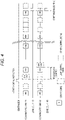
Fig. 4 is a time chart for illustrating operations of the communication system shown inFig. 1 . - A specific embodiment according to the present invention will be described below with reference to the accompanying drawings.
-
Fig. 1 is a block diagram showing an embodiment of acommunication system 1 according to the present invention. Thecommunication system 1 according to the present embodiment is mounted on avehicle 100. Thecommunication system 1 includes a plurality of communication buses B1 (first bus), communication buses B2 (second bus), a central ECU 2 (superior control device), a plurality ofzone ECUs 31 to 34 (first subordinate control device), and a plurality ofzone ECUs 41 to 44 (second subordinate control device). - The plurality of communication buses B1, B2 are connected between, for example, the
central ECU 2 disposed in an instrument panel of thevehicle 100 and thezone ECUs 31 to 34 and 41 to 44 disposed in respective areas of thevehicle 100. In the present embodiment, the communication buses B1 are connected between thecentral ECU 2 and the plurality ofzone ECUs 31 to 34 disposed in a left area of thevehicle 100. The communication buses B2 are connected between thecentral ECU 2 and the plurality ofzone ECUs 41 to 44 disposed in a right area of thevehicle 100. - In the present embodiment, an example in which the communication buses B1, B2 are provided corresponding to the left and right areas will be described, but the present invention is not limited thereto. The communication buses B1, B2 may be provided corresponding to the respective areas of the
vehicle 100. For example, thevehicle 100 may be divided into a front area and a rear area, thecentral ECU 2 and thezone ECUs 31 to 34 disposed in the front area may be connected by the communication buses B1 corresponding to the front area, and thecentral ECU 2 and thezone ECUs 41 to 44 disposed in the rear area may be connected by the communication buses B2 corresponding to the rear area. - The
central ECU 2 includes a microcomputer having a CPU, and controls theentire communication system 1. - The plurality of
zone ECUs 31 to 34 are disposed in the left area of thevehicle 100. The plurality ofzone ECUs 41 to 44 are disposed in the right area of thevehicle 100. In the present embodiment, thezone ECUs vehicle 100, thezone ECUs vehicle 100, and thezone ECUs vehicle 100. - The
zone ECUs 31 to 34 and 41 to 44 communicate with thecentral ECU 2 andcontrol lamps 51 to 53 and 61 to 63 disposed in the respective areas depending on control signals transmitted from thecentral ECU 2. Thelamps 51 to 53 are disposed in the left area of thevehicle 100. Thelamps 61 to 63 are disposed in the right area of thevehicle 100. Thelamps vehicle 100, and are turned on and off at the same time. Thelamps lamps vehicle 100, and are turned on and off at the same time. - The
lamps 51 to 53 are connected to and controlled by thezone ECUs 31 to 33, respectively. Thelamps 61 to 63 are connected to and controlled by thezone ECUs 41 to 43, respectively. In the example shown inFig. 1 , thezone ECUs 31 to 33 and 41 to 43 are also connected with powertrain-system electrical devices and chassis-system electrical devices in addition to thelamps 51 to 53 and 61 to 63. - The
communication system 1 according to the present embodiment employs a multi-master system in which equal bus access can be implemented in thecentral ECU 2 and thezone ECUs 31 to 34 and 41 to 44. In the multi-master system, thecentral ECU 2 and thezone ECUs 31 to 34 and 41 to 44 determine whether other ECUs are performing signal transmission to the communication buses B1, B2 based on voltage levels of the communication buses B1, B2. When other ECUs are not performing the signal transmission, thecentral ECU 2 and thezone ECUs 31 to 34 and 41 to 44 transmit signals, and when other ECUs are performing the signal transmission, thecentral ECU 2 and thezone ECUs 31 to 34 and 41 to 44 wait until the signal transmission is completed and transmit the signals. - In addition, the
communication system 1 according to the present embodiment employs CSMA/CA (Carrier Sense Multiplex Access with Collision Avoidance) in order for the plurality ofECUs ECUs ECUs ECUs - More specifically, the
ECUs Fig. 3 , an ID with all bits "0" is an ID having a highest priority, and an ID with all bits "1" is an ID having a lowest transmission priority. For example, when the ID with all bits "1" and the ID with all bits "0" are simultaneously transmitted, the ID with all bits "0" is preferentially transmitted in the communication buses B1, B2. When a signal transmitted in the ID transmission does not match the signal level of the communication buses B1, B2, theECUs ECUs - Next, a signal transmitted by the
central ECU 2 will be described. Thecentral ECU 2 functions as a first transmission unit and periodically transmits count signals to the communication buses B1, B2. A frame configuration of the count signal will be described with reference toFig. 2A . As shown inFig. 2A , the count signal includes a header, a data area, and a footer, and a time count value is included in the data area. Thecentral ECU 2 counts up the time count value every time thecentral ECU 2 transmits the count signal. The header of the count signal includes the ID indicating the transmission priority. In the present embodiment, as shown inFig. 3 , the ID with all bits "0" that has the highest priority is assigned as an ID of the count signal. - In addition, the
central ECU 2 functions as a second transmission unit, and transmits control signals for controlling thezone ECUs 31 to 34 and 41 to 44. Among the control signals, for example, a lamp control signal that is output to thezone ECUs 31 to 34 and 41 to 44 which are connected to the communication buses B1, B2 different from each other and need to operate at the same time includes a header, a data area, and a footer, and control content (turn on the lamp) and a start count value are included in the data region. The header of the lamp control signal includes the ID indicating the transmission priority. In the present embodiment, as shown inFig. 3 , an ID of the lamp control signal is assigned with an ID having a lower transmission priority than those of powertrain related control signals for controlling the powertrain-system electrical devices and chassis-system related control signals for controlling the chassis-system electrical devices. Thecentral ECU 2 transmits the lamp control signal to both of the communication buses B1, B2. - The
central ECU 2 cause the control signal to include a start count value having a shorter difference from the time count value included in the count signal transmitted immediately before as the transmission priority of the ID included in the control signal is higher. Specifically, when the time count value transmitted immediately before is 100, 105 is included as the start count value in the powertrain related control signal having a high transmission priority, and 110 is included as the start count value in the lamp control signal having a low transmission priority. As a result, the control content included in the control signal including the ID having the high transmission priority can be quickly executed. - On the other hand, the
zone ECUs 31 to 33 and 41 to 43 connected to thelamps 51 to 53 and 61 to 63 function as a first reception unit and a second reception unit, and receive the count signal and the lamp control signal. After thezone ECUs 31 to 33 and 41 to 43 receive the lamp control signal, when the count value included in the received count signal becomes equal to the start count value included in the control signal, thezone ECUs 31 to 33 and 41 to 43 turn on thelamps 51 to 53 and 61 to 63 according to the control content included in the lamp control signal. - Next, operations of the
communication system 1 described above will be described with reference to a time chart ofFig. 4 . As shown inFig. 4 , thecentral ECU 2 periodically transmits the count signals to the communication buses B1, B2. Since the count signal has the ID having the highest priority, the count signals can be transmitted to the communication buses B1, B2 with the highest priority. For this reason, as shown inFig. 4 , the count signals have almost no transmission deviation between the communication buses B1, B2. - When the
central ECU 2 determines that a hazard lighting instruction is given by a driver, thecentral ECU 2 transmits the lamp control signals to the communication buses B1, B2. In the example shown inFig. 4 , since the communication bus B1 is not in use, thecentral ECU 2 can immediately transmit the lamp control signal to the communication bus B1. Meanwhile, since another control signal is transmitted in the communication bus B2, thecentral ECU 2 waits until the transmission of the corresponding another control signal is completed and transmits the lamp control signal. Thereafter, in the example shown inFig. 4 , since the control signal of which an ID has a higher transmission priority than that of the lamp control signal is simultaneously transmitted, thecentral ECU 2 can transmit the lamp control signal by waiting further until the transmission of the control signal is completed. Therefore, a large transmission deviation of the lamp control signals occurs between the communication buses B1, B2. - However, 110 is written as the start count value in the lamp control signal. Therefore, after receiving the count signals in which "110" is written as the count value, the
zone ECUs 31 to 33 and 41 to 43 turn on thelamps 51 to 53 and 61 to 63 according to the control content included in the lamp control signals. In this manner, the count signals have almost no transmission deviation between the communication buses B1, B2. Therefore, it is possible to prevent a variation in a lighting start timing between thelamps 51 to 53 disposed in the left and thelamps 61 to 63 disposed in the right. - The present invention is not limited to the above-described embodiment, and modifications, improvements, and the like can be made as appropriate. In addition, materials, shapes, dimensions, numbers, arrangement locations, and the like of elements in the above-described embodiment are optional and not limited as long as the object of the present invention can be achieved.
- In the above-described embodiment, the ID of the count signal is set to the ID having the highest priority, but the present invention is not limited thereto. The ID of the count signal may have a higher transmission priority than that of the ID of the lamp control signal. The higher the transmission priority of the ID is, the smaller the transmission deviation to the communication buses B1, B2 is. Therefore, when the ID of the count signal is given the highest priority as in the above-described embodiment, it is possible to most prevent the variation in the lighting timing of the
lamps 51 to 53 and 61 to 63. However, even when the ID is not given the highest priority, if the transmission priority is higher than that of the ID of the lamp control signal, it is possible to prevent the variation in the lighting timing of thelamps 51 to 53 and 61 to 63. - In the above-described embodiment, the
communication system 1 includes the two communication buses B1, B2, but the present invention is not limited thereto. Thecommunication system 1 may include three or more communication buses B1, B2. - In the above-described embodiment, the
zone ECUs 31 to 33 and 41 to 43 control thelamps 51 to 53 and 61 to 63, but the present invention is not limited thereto. The electrical devices connected to thezone ECUs 31 to 33 and 41 to 43 may be front and rear brake actuators or the like. - Here, characteristics of the embodiment of the communication system, the superior control device, and the subordinate control device according to the present invention described above will be briefly summarized and listed in [1] to [5] below.
- [1]
- A communication system (1) includes:
- a superior control device (2);
- a first subordinate control device (31 to 34) capable of communicating with the superior control device (2) via a first bus (B1); and
- a second subordinate control device (41 to 44) capable of communicating with the superior control device (2) via a second bus (B2).
- The superior control device (2) includes:
- a first transmission unit (2) that periodically transmits a count signal including a count value counted up every time the count signal is transmitted to the first bus (B1) and the second bus (B2); and
- a second transmission unit (2) that transmits a control signal including a start count value and control content to the first bus (B1) and the second bus (B2).
- A transmission priority of the count signal is set to be higher than a transmission priority of the control signal.
- The first subordinate control device (31 to 34) and the second subordinate control device (41 to 44) include:
- a first reception unit (31 to 34, 41 to 44) that receives the count signal; and
- a second reception unit (31 to 34, 41 to 44) that receives the control signal.
- After the control signal is received, when the count value included in the received count signal becomes equal to the start count value included in the control signal, an operation corresponding to the control content included in the control signal is started.
- A communication system (1) includes:
- [2] In the communication system (1) according to [1],
the superior control device (2) causes the count signal to be transmitted to the first bus (B1) and the second bus (B2) with a highest priority. - [3] In the communication system (1) according to [1] or [2],
the superior control device (2) cause the control signal to include the start count value having a shorter difference from the count value included in the count signal transmitted immediately before as the transmission priority of the control signal is higher, and transmits the control signal. - [4] A superior control device (2) capable of communicating with a first subordinate control device (31 to 34) via a first bus (B1) and capable of communicating with a second subordinate control device (41 to 44) via a second bus (B2), the superior control device (2) includes:
- a first transmission unit (2) that periodically transmits a count signal including a count value counted up every time the count signal is transmitted to the first bus (B1) and the second bus (B2); and
- a second transmission unit (2) that transmits a control signal including a start count value and control content to the first bus (B1) and the second bus (B2).
- [5] A subordinate control device (31 to 34, 41 to 44) capable of communicating with a superior control device (2), the subordinate control device (31 to 34, 41 to 44) includes:
- a first reception unit (31 to 34, 41 to 44) that receives a count signal including a count value counted up every time the count signal is transmitted from the superior control device (2); and
- a second reception unit (31 to 34, 41 to 44) that receives a control signal including a start count value and control content transmitted from the superior control device (2).
- According to the communication system having the configuration of [1], when the count value of the count signal having the high transmission priority becomes the start count value included in the control signal, the first and second subordinate control devices start the operation according to the control content included in the control signal. Accordingly, it is possible to prevent a variation in an operation start timing between the first and second subordinate control devices.
- According to the communication system having the configuration of [2], the superior control device causes the count signal to be transmitted to the first bus and the second bus with the highest priority. Accordingly, it is possible to further prevent the variation in the operation start timing between the first and second subordinate control devices.
- According to the communication system having the configuration of [3], the control content included in the control signal having the transmission priority can be quickly executed.
- According to the superior control device having the configuration of [4], the count signal including the count value counted up every time the count signal is transmitted is periodically transmitted to the first and second buses, and the control signal including the start count value and the control content is transmitted to the first and second buses. Accordingly, when the count value of the count signal becomes the start count value included in the control signal, the subordinate control devices connected to the first and second buses can start the operation according to the control content included in the control signal. Accordingly, it is possible to prevent a variation in an operation start timing between the first and second subordinate control devices.
- According to the subordinate control device having the configuration of [5], after the control signal is received, when the count value included in the received count signal becomes equal to the start count value included in the control signal, the operation corresponding to the control content included in the control signal is started. As a result, it is possible to prevent the variation in the operation start timing between the subordinate control devices connected to the different buses.
- According to the present invention, it is possible to provide a communication system capable of preventing a variation in an operation start timing between subordinate control devices to which different buses are connected, a superior control device, and a subordinate control device.
Claims (5)
- A communication system (1) comprising:a superior control device (2);a first subordinate control device (31 to 34) capable of communicating with the superior control device (2) via a first bus (B1); anda second subordinate control device (41 to 44) capable of communicating with the superior control device (2) via a second bus (B2),wherein the superior control device (2) includesa first transmission unit (2) configured to periodically transmit, to the first bus (B1) and the second bus (B2), a count signal including a count value counted up every time the count signal is transmitted, anda second transmission unit (2) configured to transmit a control signal including a start count value and control content to the first bus (B1) and the second bus (B2),wherein a transmission priority of the count signal is set to be higher than a transmission priority of the control signal,wherein the first subordinate control device (31 to 34) and the second subordinate control device (41 to 44) include a first reception unit (31 to 34, 41 to 44) configured to receive the count signal, and a second reception unit (31 to 34, 41 to 44) configured to receive the control signal, andwherein after the control signal is received, when the count value included in the received count signal becomes equal to the start count value included in the control signal, an operation corresponding to the control content included in the control signal is started.
- The communication system (1) according to claim 1,
wherein the superior control device (2) causes the count signal to be transmitted to the first bus (B1) and the second bus (B2) with a highest priority. - The communication system according to claim 1 or 2,
wherein the superior control device (2) causes the control signal to include the start count value having a shorter difference from the count value included in the count signal transmitted immediately before as the transmission priority of the control signal is higher, and transmits the control signal. - A superior control device (2) capable of communicating with a first subordinate control device (31 to 34) via a first bus (B1) and capable of communicating with a second subordinate control device (41 to 44) via a second bus (B2), the superior control device (2) comprising:a first transmission unit (2) configured to periodically transmit, to the first bus (B1) and the second bus (B2), a count signal including a count value counted up every time the count signal is transmitted; anda second transmission unit (2) configured to transmit a control signal including a start count value and control content to the first bus (B1) and the second bus (B2),wherein a transmission priority of the count signal is set to be higher than a transmission priority of the control signal.
- A subordinate control device (31 to 34, 41 to 44) capable of communicating with a superior control device (2), the subordinate control device (31 to 34, 41 to 44) comprising:a first reception unit (31 to 34, 41 to 44) configured to receive a count signal including a count value counted up every time the count signal is transmitted from the superior control device (2); anda second reception unit (31 to 34, 41 to 44) configured to receive a control signal including a start count value and control content transmitted from the superior control device (2),wherein after the control signal is received, when the count value included in the received count signal becomes equal to the start count value included in the control signal, an operation corresponding to the control content included in the control signal is started.
Applications Claiming Priority (1)
| Application Number | Priority Date | Filing Date | Title |
|---|---|---|---|
| JP2021098245A JP7410085B2 (en) | 2021-06-11 | 2021-06-11 | Communication system and upper control device |
Publications (2)
| Publication Number | Publication Date |
|---|---|
| EP4102779A1 true EP4102779A1 (en) | 2022-12-14 |
| EP4102779B1 EP4102779B1 (en) | 2023-11-29 |
Family
ID=81940482
Family Applications (1)
| Application Number | Title | Priority Date | Filing Date |
|---|---|---|---|
| EP22177201.5A Active EP4102779B1 (en) | 2021-06-11 | 2022-06-03 | Synchronous command execution between a superior control device and subordinate control devices |
Country Status (4)
| Country | Link |
|---|---|
| US (1) | US11809357B2 (en) |
| EP (1) | EP4102779B1 (en) |
| JP (1) | JP7410085B2 (en) |
| CN (1) | CN115469633B (en) |
Citations (6)
| Publication number | Priority date | Publication date | Assignee | Title |
|---|---|---|---|---|
| JP2002254996A (en) | 2001-03-02 | 2002-09-11 | Yazaki Corp | Node protection system and node protection device |
| JP2002261780A (en) | 2001-03-02 | 2002-09-13 | Yazaki Corp | Node protection system and node protection device |
| US6484082B1 (en) * | 2000-05-24 | 2002-11-19 | General Motors Corporation | In-vehicle network management using virtual networks |
| US20180307635A1 (en) * | 2015-10-13 | 2018-10-25 | Autoliv Developmen Ab | A vehicle safety electronic control system |
| US20190041933A1 (en) * | 2009-05-20 | 2019-02-07 | Renesas Electronics Corporation | Method of controlling electronic controller units |
| WO2021020211A1 (en) * | 2019-07-31 | 2021-02-04 | マツダ株式会社 | Vehicle control system |
Family Cites Families (10)
| Publication number | Priority date | Publication date | Assignee | Title |
|---|---|---|---|---|
| JP2009163624A (en) * | 2008-01-09 | 2009-07-23 | Nec Electronics Corp | Processor device and conditional branch processing method |
| JP2011142505A (en) | 2010-01-07 | 2011-07-21 | Sumitomo Electric Ind Ltd | Pon system, optical line terminal and optical network unit of the same, and oam link state determination method |
| JP5794449B2 (en) | 2010-03-15 | 2015-10-14 | オムロン株式会社 | Programmable controller |
| JP5625766B2 (en) * | 2010-11-08 | 2014-11-19 | ソニー株式会社 | Arbitration circuit and control method thereof |
| US8504864B2 (en) * | 2010-12-01 | 2013-08-06 | GM Global Technology Operations LLC | Data sensor coordination using time synchronization in a multi-bus controller area network system |
| JP5459628B2 (en) | 2012-01-12 | 2014-04-02 | 横河電機株式会社 | Time synchronization system |
| JP6056363B2 (en) * | 2012-10-12 | 2017-01-11 | 株式会社ソシオネクスト | Processing device and control method of processing device |
| DE202017104362U1 (en) * | 2017-07-21 | 2017-08-07 | Robert Bosch Gmbh | Timestamp unit and communication control unit for a subscriber station of a communication network |
| JP7251346B2 (en) | 2019-06-19 | 2023-04-04 | 株式会社デンソー | Master relay device and relay system |
| JP7294085B2 (en) | 2019-11-25 | 2023-06-20 | オムロン株式会社 | Control system, control device and control method |
-
2021
- 2021-06-11 JP JP2021098245A patent/JP7410085B2/en active Active
-
2022
- 2022-06-03 EP EP22177201.5A patent/EP4102779B1/en active Active
- 2022-06-07 CN CN202210638922.XA patent/CN115469633B/en active Active
- 2022-06-10 US US17/837,034 patent/US11809357B2/en active Active
Patent Citations (7)
| Publication number | Priority date | Publication date | Assignee | Title |
|---|---|---|---|---|
| US6484082B1 (en) * | 2000-05-24 | 2002-11-19 | General Motors Corporation | In-vehicle network management using virtual networks |
| JP2002254996A (en) | 2001-03-02 | 2002-09-11 | Yazaki Corp | Node protection system and node protection device |
| JP2002261780A (en) | 2001-03-02 | 2002-09-13 | Yazaki Corp | Node protection system and node protection device |
| US20190041933A1 (en) * | 2009-05-20 | 2019-02-07 | Renesas Electronics Corporation | Method of controlling electronic controller units |
| US20180307635A1 (en) * | 2015-10-13 | 2018-10-25 | Autoliv Developmen Ab | A vehicle safety electronic control system |
| WO2021020211A1 (en) * | 2019-07-31 | 2021-02-04 | マツダ株式会社 | Vehicle control system |
| US20220274523A1 (en) * | 2019-07-31 | 2022-09-01 | Mazda Motor Corporation | Vehicle control system |
Also Published As
| Publication number | Publication date |
|---|---|
| JP7410085B2 (en) | 2024-01-09 |
| EP4102779B1 (en) | 2023-11-29 |
| US11809357B2 (en) | 2023-11-07 |
| US20220398209A1 (en) | 2022-12-15 |
| CN115469633A (en) | 2022-12-13 |
| CN115469633B (en) | 2025-07-22 |
| JP2022189586A (en) | 2022-12-22 |
Similar Documents
| Publication | Publication Date | Title |
|---|---|---|
| KR100679858B1 (en) | Message delivery device based on dynamic priority, priority control device and dynamic priority message processing method using the same | |
| KR102881914B1 (en) | Communication method for ethernet network of vehicle | |
| JP6768614B2 (en) | In-vehicle network device | |
| US20120290753A1 (en) | Connection method for bus controllers and communication system | |
| KR102044723B1 (en) | Subscriber station of a bus system and method for transferring messages between subscriber stations of a bus system | |
| US12388767B2 (en) | Vehicle network and method of communication | |
| US11689296B2 (en) | On-board communication system, optical coupler, and on-board device | |
| JP2011109452A (en) | In-vehicle communication system | |
| US9478982B2 (en) | Power supply system and method | |
| US10484202B2 (en) | Relay device, electronic control device, and vehicle-mounted network system | |
| US11809357B2 (en) | Communication system, superior control device and subordinate control device | |
| KR20130057568A (en) | Can network system for vehicle | |
| KR101603546B1 (en) | Method and apparatus for providing vehicle communication network | |
| US10972307B2 (en) | Communication system | |
| JP2009010852A (en) | On-vehicle gateway device | |
| KR101165046B1 (en) | Controller area network-bus controlling module and the controlling mehod therof | |
| JP2009089286A (en) | Relay connection unit | |
| JP2005277896A (en) | In-vehicle network expansion device and in-vehicle electronic control unit | |
| JP5078003B2 (en) | In-vehicle device communication system and distribution device | |
| JP2018121155A (en) | Vehicle controller | |
| JP2006192970A (en) | In-vehicle communication connection device and in-vehicle communication system | |
| US6651112B1 (en) | Data transmission between connected modules wherein each module separately and directly communication with each other modules | |
| JP2011055112A (en) | Communication system and communication device | |
| KR101988171B1 (en) | Device for providing speed-enhancement for connected nodes on a bus | |
| US10567193B2 (en) | In-vehicle control device |
Legal Events
| Date | Code | Title | Description |
|---|---|---|---|
| PUAI | Public reference made under article 153(3) epc to a published international application that has entered the european phase |
Free format text: ORIGINAL CODE: 0009012 |
|
| STAA | Information on the status of an ep patent application or granted ep patent |
Free format text: STATUS: REQUEST FOR EXAMINATION WAS MADE |
|
| 17P | Request for examination filed |
Effective date: 20220603 |
|
| AK | Designated contracting states |
Kind code of ref document: A1 Designated state(s): AL AT BE BG CH CY CZ DE DK EE ES FI FR GB GR HR HU IE IS IT LI LT LU LV MC MK MT NL NO PL PT RO RS SE SI SK SM TR |
|
| STAA | Information on the status of an ep patent application or granted ep patent |
Free format text: STATUS: EXAMINATION IS IN PROGRESS |
|
| 17Q | First examination report despatched |
Effective date: 20230317 |
|
| RAP3 | Party data changed (applicant data changed or rights of an application transferred) |
Owner name: YAZAKI CORPORATION |
|
| GRAP | Despatch of communication of intention to grant a patent |
Free format text: ORIGINAL CODE: EPIDOSNIGR1 |
|
| STAA | Information on the status of an ep patent application or granted ep patent |
Free format text: STATUS: GRANT OF PATENT IS INTENDED |
|
| INTG | Intention to grant announced |
Effective date: 20230629 |
|
| GRAS | Grant fee paid |
Free format text: ORIGINAL CODE: EPIDOSNIGR3 |
|
| GRAA | (expected) grant |
Free format text: ORIGINAL CODE: 0009210 |
|
| STAA | Information on the status of an ep patent application or granted ep patent |
Free format text: STATUS: THE PATENT HAS BEEN GRANTED |
|
| AK | Designated contracting states |
Kind code of ref document: B1 Designated state(s): AL AT BE BG CH CY CZ DE DK EE ES FI FR GB GR HR HU IE IS IT LI LT LU LV MC MK MT NL NO PL PT RO RS SE SI SK SM TR |
|
| REG | Reference to a national code |
Ref country code: GB Ref legal event code: FG4D |
|
| REG | Reference to a national code |
Ref country code: CH Ref legal event code: EP |
|
| REG | Reference to a national code |
Ref country code: DE Ref legal event code: R096 Ref document number: 602022001148 Country of ref document: DE |
|
| REG | Reference to a national code |
Ref country code: IE Ref legal event code: FG4D |
|
| REG | Reference to a national code |
Ref country code: LT Ref legal event code: MG9D |
|
| REG | Reference to a national code |
Ref country code: NL Ref legal event code: MP Effective date: 20231129 |
|
| PG25 | Lapsed in a contracting state [announced via postgrant information from national office to epo] |
Ref country code: GR Free format text: LAPSE BECAUSE OF FAILURE TO SUBMIT A TRANSLATION OF THE DESCRIPTION OR TO PAY THE FEE WITHIN THE PRESCRIBED TIME-LIMIT Effective date: 20240301 |
|
| PG25 | Lapsed in a contracting state [announced via postgrant information from national office to epo] |
Ref country code: IS Free format text: LAPSE BECAUSE OF FAILURE TO SUBMIT A TRANSLATION OF THE DESCRIPTION OR TO PAY THE FEE WITHIN THE PRESCRIBED TIME-LIMIT Effective date: 20240329 |
|
| PG25 | Lapsed in a contracting state [announced via postgrant information from national office to epo] |
Ref country code: LT Free format text: LAPSE BECAUSE OF FAILURE TO SUBMIT A TRANSLATION OF THE DESCRIPTION OR TO PAY THE FEE WITHIN THE PRESCRIBED TIME-LIMIT Effective date: 20231129 |
|
| PG25 | Lapsed in a contracting state [announced via postgrant information from national office to epo] |
Ref country code: ES Free format text: LAPSE BECAUSE OF FAILURE TO SUBMIT A TRANSLATION OF THE DESCRIPTION OR TO PAY THE FEE WITHIN THE PRESCRIBED TIME-LIMIT Effective date: 20231129 |
|
| PG25 | Lapsed in a contracting state [announced via postgrant information from national office to epo] |
Ref country code: LT Free format text: LAPSE BECAUSE OF FAILURE TO SUBMIT A TRANSLATION OF THE DESCRIPTION OR TO PAY THE FEE WITHIN THE PRESCRIBED TIME-LIMIT Effective date: 20231129 Ref country code: IS Free format text: LAPSE BECAUSE OF FAILURE TO SUBMIT A TRANSLATION OF THE DESCRIPTION OR TO PAY THE FEE WITHIN THE PRESCRIBED TIME-LIMIT Effective date: 20240329 Ref country code: GR Free format text: LAPSE BECAUSE OF FAILURE TO SUBMIT A TRANSLATION OF THE DESCRIPTION OR TO PAY THE FEE WITHIN THE PRESCRIBED TIME-LIMIT Effective date: 20240301 Ref country code: ES Free format text: LAPSE BECAUSE OF FAILURE TO SUBMIT A TRANSLATION OF THE DESCRIPTION OR TO PAY THE FEE WITHIN THE PRESCRIBED TIME-LIMIT Effective date: 20231129 Ref country code: BG Free format text: LAPSE BECAUSE OF FAILURE TO SUBMIT A TRANSLATION OF THE DESCRIPTION OR TO PAY THE FEE WITHIN THE PRESCRIBED TIME-LIMIT Effective date: 20240229 |
|
| REG | Reference to a national code |
Ref country code: AT Ref legal event code: MK05 Ref document number: 1637253 Country of ref document: AT Kind code of ref document: T Effective date: 20231129 |
|
| PG25 | Lapsed in a contracting state [announced via postgrant information from national office to epo] |
Ref country code: NL Free format text: LAPSE BECAUSE OF FAILURE TO SUBMIT A TRANSLATION OF THE DESCRIPTION OR TO PAY THE FEE WITHIN THE PRESCRIBED TIME-LIMIT Effective date: 20231129 |
|
| PG25 | Lapsed in a contracting state [announced via postgrant information from national office to epo] |
Ref country code: SE Free format text: LAPSE BECAUSE OF FAILURE TO SUBMIT A TRANSLATION OF THE DESCRIPTION OR TO PAY THE FEE WITHIN THE PRESCRIBED TIME-LIMIT Effective date: 20231129 Ref country code: RS Free format text: LAPSE BECAUSE OF FAILURE TO SUBMIT A TRANSLATION OF THE DESCRIPTION OR TO PAY THE FEE WITHIN THE PRESCRIBED TIME-LIMIT Effective date: 20231129 Ref country code: PL Free format text: LAPSE BECAUSE OF FAILURE TO SUBMIT A TRANSLATION OF THE DESCRIPTION OR TO PAY THE FEE WITHIN THE PRESCRIBED TIME-LIMIT Effective date: 20231129 Ref country code: NO Free format text: LAPSE BECAUSE OF FAILURE TO SUBMIT A TRANSLATION OF THE DESCRIPTION OR TO PAY THE FEE WITHIN THE PRESCRIBED TIME-LIMIT Effective date: 20240229 Ref country code: NL Free format text: LAPSE BECAUSE OF FAILURE TO SUBMIT A TRANSLATION OF THE DESCRIPTION OR TO PAY THE FEE WITHIN THE PRESCRIBED TIME-LIMIT Effective date: 20231129 Ref country code: LV Free format text: LAPSE BECAUSE OF FAILURE TO SUBMIT A TRANSLATION OF THE DESCRIPTION OR TO PAY THE FEE WITHIN THE PRESCRIBED TIME-LIMIT Effective date: 20231129 Ref country code: HR Free format text: LAPSE BECAUSE OF FAILURE TO SUBMIT A TRANSLATION OF THE DESCRIPTION OR TO PAY THE FEE WITHIN THE PRESCRIBED TIME-LIMIT Effective date: 20231129 |
|
| PG25 | Lapsed in a contracting state [announced via postgrant information from national office to epo] |
Ref country code: DK Free format text: LAPSE BECAUSE OF FAILURE TO SUBMIT A TRANSLATION OF THE DESCRIPTION OR TO PAY THE FEE WITHIN THE PRESCRIBED TIME-LIMIT Effective date: 20231129 |
|
| PG25 | Lapsed in a contracting state [announced via postgrant information from national office to epo] |
Ref country code: CZ Free format text: LAPSE BECAUSE OF FAILURE TO SUBMIT A TRANSLATION OF THE DESCRIPTION OR TO PAY THE FEE WITHIN THE PRESCRIBED TIME-LIMIT Effective date: 20231129 Ref country code: AT Free format text: LAPSE BECAUSE OF FAILURE TO SUBMIT A TRANSLATION OF THE DESCRIPTION OR TO PAY THE FEE WITHIN THE PRESCRIBED TIME-LIMIT Effective date: 20231129 |
|
| PG25 | Lapsed in a contracting state [announced via postgrant information from national office to epo] |
Ref country code: SK Free format text: LAPSE BECAUSE OF FAILURE TO SUBMIT A TRANSLATION OF THE DESCRIPTION OR TO PAY THE FEE WITHIN THE PRESCRIBED TIME-LIMIT Effective date: 20231129 |
|
| PG25 | Lapsed in a contracting state [announced via postgrant information from national office to epo] |
Ref country code: SM Free format text: LAPSE BECAUSE OF FAILURE TO SUBMIT A TRANSLATION OF THE DESCRIPTION OR TO PAY THE FEE WITHIN THE PRESCRIBED TIME-LIMIT Effective date: 20231129 Ref country code: SK Free format text: LAPSE BECAUSE OF FAILURE TO SUBMIT A TRANSLATION OF THE DESCRIPTION OR TO PAY THE FEE WITHIN THE PRESCRIBED TIME-LIMIT Effective date: 20231129 Ref country code: RO Free format text: LAPSE BECAUSE OF FAILURE TO SUBMIT A TRANSLATION OF THE DESCRIPTION OR TO PAY THE FEE WITHIN THE PRESCRIBED TIME-LIMIT Effective date: 20231129 Ref country code: IT Free format text: LAPSE BECAUSE OF FAILURE TO SUBMIT A TRANSLATION OF THE DESCRIPTION OR TO PAY THE FEE WITHIN THE PRESCRIBED TIME-LIMIT Effective date: 20231129 Ref country code: EE Free format text: LAPSE BECAUSE OF FAILURE TO SUBMIT A TRANSLATION OF THE DESCRIPTION OR TO PAY THE FEE WITHIN THE PRESCRIBED TIME-LIMIT Effective date: 20231129 Ref country code: DK Free format text: LAPSE BECAUSE OF FAILURE TO SUBMIT A TRANSLATION OF THE DESCRIPTION OR TO PAY THE FEE WITHIN THE PRESCRIBED TIME-LIMIT Effective date: 20231129 Ref country code: CZ Free format text: LAPSE BECAUSE OF FAILURE TO SUBMIT A TRANSLATION OF THE DESCRIPTION OR TO PAY THE FEE WITHIN THE PRESCRIBED TIME-LIMIT Effective date: 20231129 Ref country code: AT Free format text: LAPSE BECAUSE OF FAILURE TO SUBMIT A TRANSLATION OF THE DESCRIPTION OR TO PAY THE FEE WITHIN THE PRESCRIBED TIME-LIMIT Effective date: 20231129 |
|
| PG25 | Lapsed in a contracting state [announced via postgrant information from national office to epo] |
Ref country code: PT Free format text: LAPSE BECAUSE OF FAILURE TO SUBMIT A TRANSLATION OF THE DESCRIPTION OR TO PAY THE FEE WITHIN THE PRESCRIBED TIME-LIMIT Effective date: 20240401 |
|
| PG25 | Lapsed in a contracting state [announced via postgrant information from national office to epo] |
Ref country code: PT Free format text: LAPSE BECAUSE OF FAILURE TO SUBMIT A TRANSLATION OF THE DESCRIPTION OR TO PAY THE FEE WITHIN THE PRESCRIBED TIME-LIMIT Effective date: 20240401 |
|
| REG | Reference to a national code |
Ref country code: DE Ref legal event code: R097 Ref document number: 602022001148 Country of ref document: DE |
|
| PLBE | No opposition filed within time limit |
Free format text: ORIGINAL CODE: 0009261 |
|
| STAA | Information on the status of an ep patent application or granted ep patent |
Free format text: STATUS: NO OPPOSITION FILED WITHIN TIME LIMIT |
|
| PG25 | Lapsed in a contracting state [announced via postgrant information from national office to epo] |
Ref country code: SI Free format text: LAPSE BECAUSE OF FAILURE TO SUBMIT A TRANSLATION OF THE DESCRIPTION OR TO PAY THE FEE WITHIN THE PRESCRIBED TIME-LIMIT Effective date: 20231129 |
|
| PG25 | Lapsed in a contracting state [announced via postgrant information from national office to epo] |
Ref country code: SI Free format text: LAPSE BECAUSE OF FAILURE TO SUBMIT A TRANSLATION OF THE DESCRIPTION OR TO PAY THE FEE WITHIN THE PRESCRIBED TIME-LIMIT Effective date: 20231129 |
|
| 26N | No opposition filed |
Effective date: 20240830 |
|
| PG25 | Lapsed in a contracting state [announced via postgrant information from national office to epo] |
Ref country code: MC Free format text: LAPSE BECAUSE OF FAILURE TO SUBMIT A TRANSLATION OF THE DESCRIPTION OR TO PAY THE FEE WITHIN THE PRESCRIBED TIME-LIMIT Effective date: 20231129 |
|
| PG25 | Lapsed in a contracting state [announced via postgrant information from national office to epo] |
Ref country code: LU Free format text: LAPSE BECAUSE OF NON-PAYMENT OF DUE FEES Effective date: 20240603 |
|
| PG25 | Lapsed in a contracting state [announced via postgrant information from national office to epo] |
Ref country code: IE Free format text: LAPSE BECAUSE OF NON-PAYMENT OF DUE FEES Effective date: 20240603 |
|
| PG25 | Lapsed in a contracting state [announced via postgrant information from national office to epo] |
Ref country code: BE Free format text: LAPSE BECAUSE OF NON-PAYMENT OF DUE FEES Effective date: 20240630 |
|
| PG25 | Lapsed in a contracting state [announced via postgrant information from national office to epo] |
Ref country code: FR Free format text: LAPSE BECAUSE OF NON-PAYMENT OF DUE FEES Effective date: 20240630 |
|
| REG | Reference to a national code |
Ref country code: BE Ref legal event code: MM Effective date: 20240630 |
|
| PGFP | Annual fee paid to national office [announced via postgrant information from national office to epo] |
Ref country code: DE Payment date: 20250429 Year of fee payment: 4 |
|
| PG25 | Lapsed in a contracting state [announced via postgrant information from national office to epo] |
Ref country code: CY Free format text: LAPSE BECAUSE OF FAILURE TO SUBMIT A TRANSLATION OF THE DESCRIPTION OR TO PAY THE FEE WITHIN THE PRESCRIBED TIME-LIMIT; INVALID AB INITIO Effective date: 20220603 |
|
| PG25 | Lapsed in a contracting state [announced via postgrant information from national office to epo] |
Ref country code: FI Free format text: LAPSE BECAUSE OF FAILURE TO SUBMIT A TRANSLATION OF THE DESCRIPTION OR TO PAY THE FEE WITHIN THE PRESCRIBED TIME-LIMIT Effective date: 20231129 |
|
| REG | Reference to a national code |
Ref country code: CH Ref legal event code: H13 Free format text: ST27 STATUS EVENT CODE: U-0-0-H10-H13 (AS PROVIDED BY THE NATIONAL OFFICE) Effective date: 20260127 |
|
| PG25 | Lapsed in a contracting state [announced via postgrant information from national office to epo] |
Ref country code: HU Free format text: LAPSE BECAUSE OF FAILURE TO SUBMIT A TRANSLATION OF THE DESCRIPTION OR TO PAY THE FEE WITHIN THE PRESCRIBED TIME-LIMIT; INVALID AB INITIO Effective date: 20220603 |
|
| PG25 | Lapsed in a contracting state [announced via postgrant information from national office to epo] |
Ref country code: CH Free format text: LAPSE BECAUSE OF NON-PAYMENT OF DUE FEES Effective date: 20250630 |